Article

Behaviour of a Sacrificial Cladding with Foam Concrete-Filled Square Tubes under Impact Loads

1
Key Lab of Structures Dynamic Behavior and Control of the Ministry of Education, Harbin Institute of Technology, Harbin 150090, China
2
Key Lab of Smart Prevention and Mitigation of Civil Engineering Disasters of the Ministry of Industry and Information Technology, Harbin Institute of Technology, Harbin 150090, China
*
Author to whom correspondence should be addressed.
Buildings 2023, 13(7), 1774; https://doi.org/10.3390/buildings13071774
Submission received: 15 June 2023 / Revised: 3 July 2023 / Accepted: 10 July 2023 / Published: 12 July 2023

Abstract

:
In this paper, a new sacrificial cladding with foam concrete-filled square tubes (FCFST sacrificial cladding) was developed for dissipating impact energy. The impact experiment was conducted on the FCFST sacrificial claddings using a drop hammer impact experiment system, and the finite element simulation analysis was performed using the explicit nonlinear program LS-DYNA. The deformation modes, force–displacement responses and energy absorption performances of the FCFST sacrificial claddings were discussed. The results indicated that the impact responses of the FCFST sacrificial cladding could be classified into four stages, and the energy absorption performance could be enhanced by increasing the contact area between the sacrificial cladding and impactor. Foam concrete-filled tubes that underwent obvious plastic deformation dissipated more impact energy than other parts of the sacrificial cladding, and three deformation modes could be identified in theses tubes. Furthermore, the effects of the thickness ratio of the top plate to tube, width-to-thickness ratio of the tube and impact location on the impact behaviour of the FCFST sacrificial cladding were numerically studied. It was found that decreasing the thickness ratio of the top plate to tube could enhance the energy absorption performance of the FCFST sacrificial cladding. However, the impact location was found to have little effect on the energy absorption unless it was close to the edge of the sacrificial cladding.

1. Introduction

With the increase in building and infrastructure damage caused by terrorist attacks and vehicle impacts over the past years [1,2,3], taking preventive solutions to protect buildings and infrastructures is becoming urgent [4,5]. Out of many proposed solutions, the sandwich-type sacrificial cladding has attached much attention in building protection due to its excellent energy dissipation and blast mitigation performance [6]. Therefore, it is necessary to develop a new sandwich-type sacrificial cladding and investigate its dynamic responses and energy absorption performance under impact loads.
The sandwich-type sacrificial cladding typically consists of a top plate, a bottom plate fixed to buildings and infrastructures and an energy absorbing core sandwiched between the two plates [7]. The energy absorbing core always allows for large plastic deformation under relatively low stress, which effectively dissipates impact energy and reduces the force transmitted to buildings and infrastructures. Hence, the design of an energy absorbing core is of vital importance to enhance the protection capacity of sandwich-type sacrificial cladding. Numerous studies have been conducted on thin-walled tubes owing to their excellent energy dissipation performance and simple fabrication process [8,9]. The laterally-loaded tube would undergo obvious plastic deformation and dissipate energy effectively [10], and constraining the lateral movement could lead to a better energy absorption performance [11]. Compared to lateral loading, the thin-walled tube exhibits much better specific energy absorption under axial crushing [12]. This is because the majority of the material in the axially-loaded tubes undergo plastic deformation and participates in the energy dissipation process [13]. Several theoretical predictions [14,15,16] were developed for calculating the mean crushing force of axially-loaded tube. In addition, it has been demonstrated that the cross-section dimensions (diameter and thickness) [17,18] and length [19] play a major role in the deformation mode of thin-walled tubes. Recently, foam materials have received much attention due to their lightweight and high specific energy absorption characteristics, and they have great potential in reinforcing thin-walled tubes as fillers [20]. Reid et al. [21] reported that polyurethane foam-filled tubes exhibit greater energy absorption and better stability than empty tubes owing to the interaction between the tubes and the polyurethane foam. Furthermore, aluminium foam has been shown to be effective in enhancing the energy absorption capacity of square tubes [22]. In contrast to popular foam materials like polyurethane foam and aluminium foam, foam concrete is more suitable for civil engineering owing to its low cost and high accessibility [23]. The foam concrete could absorb a large quantity of energy through the breakage of its internal cell wall, and its capacity to enhance the energy dissipation of thin-walled structures has been demonstrated [24,25]. Zhang et al. [25] studied the influence of the filling action on the deformation and energy absorption of the foam concrete-filled polyethylene pipe (FC-PE pipe) under axial compression, and the results indicated that the energy absorption of the FC-PE pipe is much higher than the sum of that of the individual components.
In recent years, numerical methods, such as the finite element model (FEM) and computational fluid dynamics (CFD), have gained increasing popularity and have found widespread application in various fields, such as civil engineering, mechanical engineering and energy [26,27,28,29]. Given the balance between accuracy and safety concerns, the integration of experimental and numerical methods has been extensively embraced in the research fields of impact and blast [30,31,32]. In addition, previous studies have shown that sandwich structures can effectively protect buildings and infrastructures from impact and blast loads by dissipating energy and reducing the force transmitted to protected objectives [33,34]. Therefore, many sandwich structures with different cores have been developed [35,36]. As a typical sandwich structure, the foam-core sandwich panel has been extensively studied for its responses under impact loads [36,37,38,39,40,41]. Kurşun et al. [40] reported that the plastic deformation and damage degree of the sandwich composite plate were significantly affected by impactor shapes. Wang et al. [41] experimentally and numerically studied the low-velocity impact behaviour of foam-core sandwich panels, and the results showed that both the indentation depth and plane damage diameter increased with the impact energy but decreased with the panel thickness. Furthermore, extensive studies have been performed on the impact response and energy absorption performance of sandwich panels with thin-walled structures (and thin-walled structures filled with foam materials) as the core [42,43,44,45,46,47]. Qin et al. [42] founded that the failure deformation mode of the sandwich panel was significantly affected by the impact position, and that the impact resistance decreased with a shift in the impact position from central to non-central. Xie et al. [43] observed that different punching diameters would result in obvious changes in the deformation of the Nomex honeycomb sandwich panel, and found that the sandwich panel was more prone to be penetrated by the sharper impactor. To optimise the energy dissipation performance of the sandwich panel they proposed, Lu et al. [47] explored the influence of the thickness ratio of the plate to core tube on the energy absorption of the sandwich plate under impact loads. The results indicated that a similar thickness of the plate and core tube led to the highest energy dissipation of the sandwich plate. In addition, the protection performance and impact behaviour of the sandwich-type sacrificial cladding under blast loads have been widely studied [48,49,50,51]. Theobald and Nurick [50] proposed a sandwich-type panel with thin-walled tubes to resist blast loads and numerically studied its dynamic response under blast loads. They found that the layout of the tubes within the panel significantly affected their stability and concluded that more tubes could lead to a higher buckling stability. Zhou et al. [51] employed foam concrete-filled aluminium tubes as the core of the sandwich sacrificial cladding and studied its protection performance experimentally and numerically. The results indicated that the residual deflection of the bottom plate (considered as the protection structure) could be controlled by filling foam concrete into the tubes, and that better protection performance could be achieved by increasing the density of the foam concrete. However, the behaviour of the sacrificial cladding with foam concrete-filled square tubes under impact loads has not been covered in the published literatures.
In this paper, a novel sandwich-type sacrificial cladding with foam concrete-filled square tubes (FCFST sacrificial cladding) was developed for building and infrastructure protection to dissipate impact energy, as shown in Figure 1. The impact behaviour of the FCFST sacrificial cladding is experimentally and numerically investigated. The flowchart of this study process is illustrated in Figure 2, and the remaining sections are organized as follows: Section 2 presents the experimental and numerical methodologies employed in this study. It includes the design of specimens, setup of the drop hammer impact experiment, the finite element (FE) model, and material models. In Section 3, the acceptability of the FE model is first verified by comparing the experimental and numerical results. The deformation mode, force–displacement response and energy absorption performance of the FCFST sacrificial claddings are discussed subsequently. Furthermore, parameter studies were conducted in FE simulations to investigate the effects of the thickness ratio of the top plate to tube, width-to-thickness ratio of the tube and impact location on the impact behaviour of the FCFST sacrificial cladding. Section 4 summarizes the key findings and conclusions derived from this study. This study is of significance for understanding the impact behaviour of the FCFST sacrificial cladding and facilitating its application as a new sacrificial cladding.

2. Methodology

2.1. Experimental Methodology

2.1.1. Specimens

The details and dimensions of the FCFST sacrificial cladding designed for the drop hammer impact experiment are shown in Figure 1. The specimen is composed of two flat plates with a thickness of 2.49 mm, 25 foam concrete blocks with a square cross-section and 25 square tubes with a thickness of 1.65 mm. Due to the low cost and high accessibility of the material (i.e., foam concrete, mild steel plate and mild steel tubes), the FCFST sacrificial cladding exhibits the potential for extensive application in building and infrastructure protection. The fabrication process of the FCFST sacrificial cladding can be divided into four steps, as illustrated in Figure 3. Firstly, slot holes for plug welds were slit on both flat plates, and bolt holes were drilled on the bottom plate. The square tubes were then temporarily fixed to the bottom plate by spot welding. The foam concrete blocks were filled into square tubes. Finally, the square tubes were fixed to the top and bottom flat plates by plug welding. Two identical specimens were prepared for the impact experiment to investigate the influence of the impactor shape (i.e., drop hammer with cylindrical head and hemispherical head) on the impact behaviour and energy absorption of the sacrificial cladding.

2.1.2. Setup of the Drop Hammer Impact Experiment

A drop hammer impact experiment system was employed to conduct the experiment on the FCFST sacrificial cladding; its photograph and 3D view are shown in Figure 4. The drop hammer impact experiment system comprises a hydraulic-controlled mechanical hosting system, a counterweight device, a hammer with a replaceable hammer head, a dynamic load cell embedded into the hammer, two guide rails, a high-speed camera and two LED lights. The hammer drops freely along the two guide rails and hits the specimen when the electromagnet release mechanism is triggered. The FCFST sacrificial cladding was fixed on a rigid support via 20 high-strength bolts with a grade of 8.8. As illustrated in Figure 4, the impact location in the experiment was located at the centre of the specimen. In addition, a hemispherical head and a cylindrical head with the same diameter of 200 mm were employed for the specimen H-SC and C-SC, respectively, as illustrated in Figure 4 (the relationships between the name of the specimen and impactor shape are shown in Table 1). The two experiments share the same drop weight of 790 kg and the same drop height of 3.85 m, and the measured hammer velocities and corresponding impact energies are listed in Table 1. The impact force was measured through employing the dynamic load cell with a measurement capacity of 2000 kN. The high-speed camera with a speed of 3000 frames per second was employed to obtain the impact process and the displacement histories of the drop hammer.

2.2. Numerical Methodology

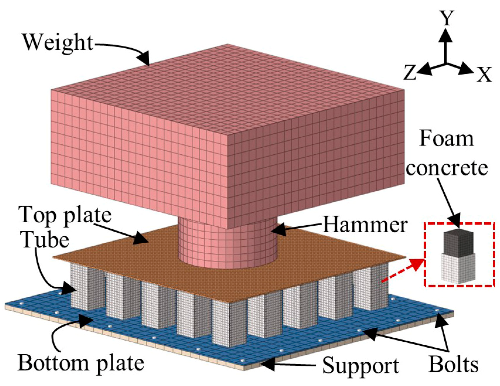
2.2.1. Finite Element Model

Apart from the experimental study, FE simulation analysis was carried out by the explicit nonlinear program LS-DYNA. The established FE model of the FCFST sacrificial cladding is presented in Figure 5, and its geometric parameters are the same as those of the specimens. The foam concrete blocks and hammer were meshed using an eight-node solid element, while the two flat plates, square tubes and support were meshed with the four-node Belytschko-Tsay shell element. Owing to the significant deformation observed during the experiment, a mesh size of 5 mm was adopted in the top plate, square tubes and foam concrete blocks. The mesh sensitivity analysis was performed by halving the size of all elements, and the impact force–displacement curves obtained from the FE simulation using current mesh and fine mesh are compared in Figure 6. Similar results can be observed for both the C-SC and H-SC, while the computation time for the fine mesh (around 9 h) is about three times than that of the current mesh. Given the balance between computational cost and accuracy, the current mesh size was employed in the FE analysis below, and a total of 103,443 elements and 127,417 nodes were used in the FE model shown in Figure 5.
With regard to the contact treatment in the FE model, the keyword “*CONTACT_AUTOMATIC_SURFACE_TO_SURFACE” in LS-DYNA was employed to model the contact of different parts. To be specific, the contacts between the foam concrete blocks and metal parts (i.e., the flat plates, hammer and square tubes) were simulated through the soft constraint-based contact algorithm, and the other contact pairs were modelled through the penalty-based contact algorithm. Meanwhile, the keyword “*CONTACT_AUTOMATIC_SINGLE_SURFACE” was utilised to simulate the self-contact of the square tubes based on the phenomenon observed in the impact experiment. Both the static and dynamic coefficient of friction applied in the above contact pairs were 0.2 [52]. In addition, the default values were selected for the remaining parameters in these contact pairs. The welding and bolting connections were defined using the keyword “*CONTACT_TIED_NODES_TO_SURFACE_OFFSET”. That is, the welding connections between the square tubes and two flat plates were simulated by tying the nodes of the square tubes in the welding area to the top and bottom plates in the FE model. As shown in Figure 5, the bolting connections between the support and bottom plate were modelled via tying the nodes of the bottom plate, which are located at the same positions as the bolts, to the support. Moreover, the boundary condition was specified by constraining all movements of the nodes of the support using the keyword “*BOUNDARY_SPC_SET”. In order to ensure that the hammer drops vertically, all movements of the hammer were constrained except for the translational degree of freedom along the Y axis direction. The keyword “*INITIAL_VELOCITY” was employed in the FE model to set the same initial impact velocity of the hammer as the experiment. As the specimen C-SC did not enter the stage of densification during the impact experiment, a higher impact energy (50 kJ) was specified in FE models by increasing the drop weight to more comprehensively explore the impact behaviour of the specimens.

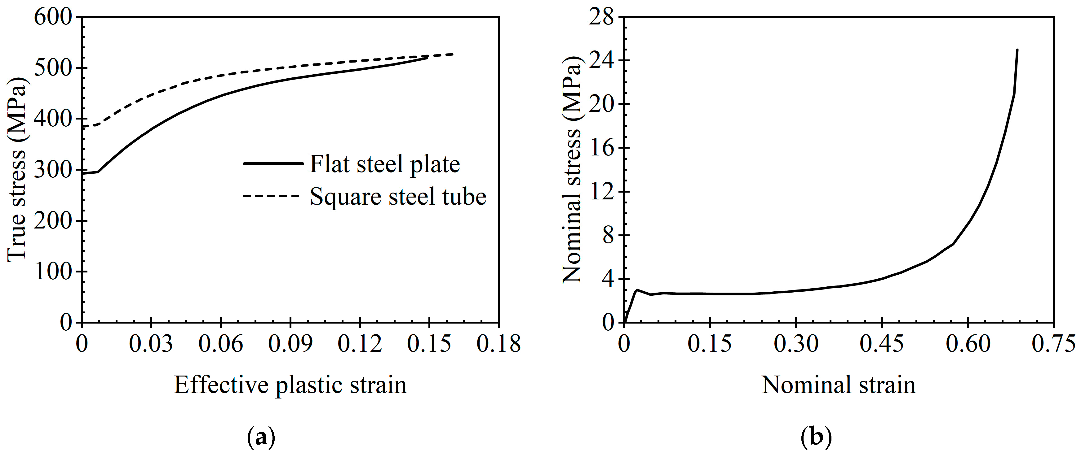
2.2.2. Material Models

Q235 steel was selected to fabricate the metal parts of the specimens, and the steel properties of the square tubes and flat plates obtained from quasi-static tensile tests are illustrated in Table 2. In addition, the true stress–effective plastic strain curves of the square tubes and flat plates are presented in Figure 7a. The material model MAT_PIECEWISE_LINEAR_PLASTICITY was selected to model the mechanical behaviour of the steel materials. In addition to the steel properties mentioned above, a failure strain of 0.15 was also defined to simulate fracture of the flat plates. The Cowper–Symonds model was employed in this material model to account for the strain–rate effect, and it can be formulated as:
σ d = [ 1 + ( ε ˙ C ) 1 P ]   σ s
where ε ˙ is the strain rate, σd is the dynamic stress with strain-rate effect, σs is the static stress without the strain–rate effect, both C and P are constitutive model parameters and are defined as 6844 s−1 and 3.91 [53], respectively.
The mechanical behaviour of the foam concrete was modelled using the material model MAT_CRUSHABLE_FOAM. Figure 7b and Table 2 present the stress–strain curve and other material parameters, respectively, inputted in the material card for the foam concrete. It should be noted that the nominal stress–volumetric strain curve required by the MAT_CRUSHABLE_FOAM model was substituted with the nominal stress–nominal strain curve obtained from the uniaxial compression test. This approximate substitution was made because the Poisson’s ratio of the foam concrete is 0.01 [51], which is close to 0. In addition, the material model MAT_PLASTIC_KINEMATIC was utilised to simulate the hammer. The hammer was assigned the same values of C and P as the steel materials of the specimens, and its other material parameters inputted into the MAT_PLASTIC_KINEMATIC are shown in Table 2.

3. Results and Discussion

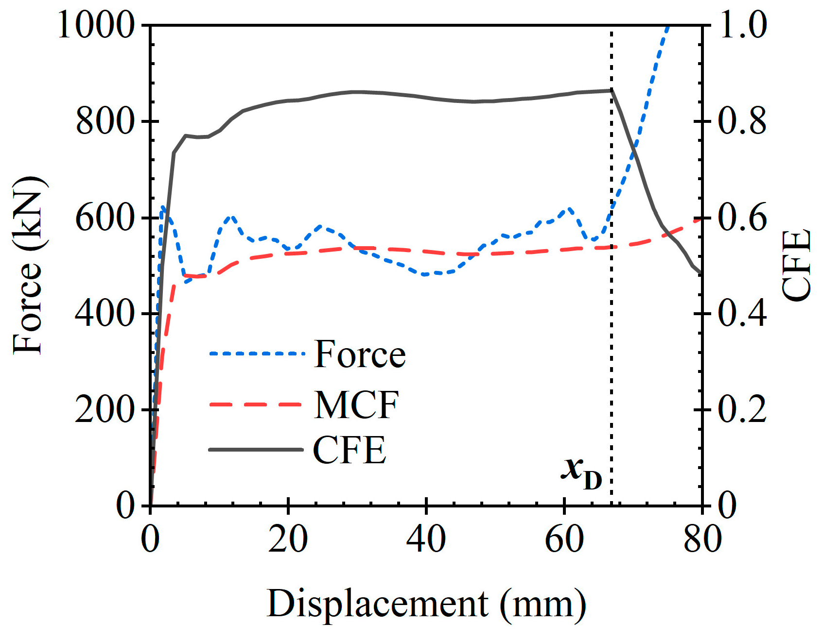
3.1. Energy Absorption Parameters

Several parameters, including the energy absorption (EA), crushing force efficiency (CFE), mean crushing force (MCF) and peak crushing force (PCF), were selected to evaluate the energy absorbing behaviour of the sacrificial cladding quantitatively. The EA is defined as:
E A = 0 x D F ( δ )   d δ
where δ and F(δ) are the displacement and crushing force, respectively; xD is the densification displacement of the sacrificial cladding, which can be determined by the CFE. The CFE is defined as the ratio of the MCF to the PCF, as shown in Equation (3).
C F E = M C F P C F
where the PCF is the maximum crushing force corresponding to a displacement ranging from 0 to δ. The MCF is defined as the ratio of the E A ( δ ) to the δ , as illustrated in Equation (4).
M C F = E A ( δ ) δ
where the E A ( δ ) is the energy absorption corresponding to the displacement δ . As illustrated in Figure 8, the sacrificial cladding reaches the densification displacement (xD) when the CFE drops continuously and suddenly [54].

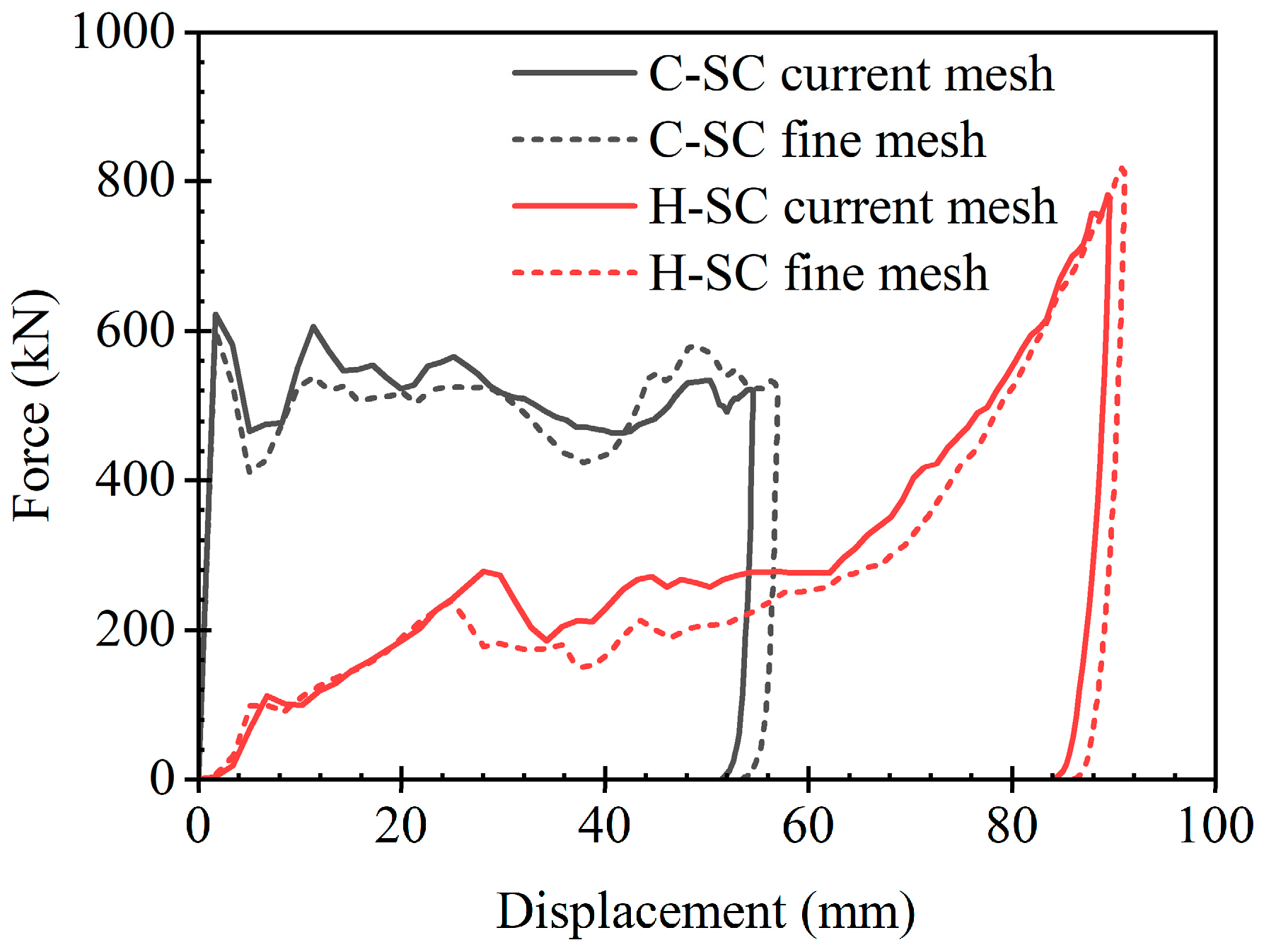
3.2. FE Model Validation

The comparison of permanent deformations of the sacrificial claddings obtained from the FE analyses and impact experiments is shown in Figure 9. The specimens were cut into two parts (as seen in Figure 9a,c) for a better comparison, since the high-speed camera was unable to record the deformation processes of specimens at their impact locations where severe damage was observed. Figure 9b,d indicate that the permanent deformations obtained from the FE analyses have good agreement with those obtained from the experiments, including the plastic deformations of the square tubes, the fracture at the impact zone of the top plates and the insignificant deformation of the bottom plates. However, some slight differences can still be found between the experiments and FE predictions. The plastic folding of the central tube of the C-SC occurs at its upper end in the experiment but at the lower end in the FE prediction, as illustrated in Figure 9b. The location of plastic folding of a foam-filled tube is random, and this inconsistent plastic folding location has little effect on the EA of the central tube, since the central tubes in the experiment and FE prediction adopt the same compact collapse mode [55]. In addition, the central tubes of the C-SC and H-SC exhibited slight oblique crushing in the experiment, whereas axial crushing was observed from the FE analysis. The oblique crushing of the central tubes may be attributed to the geometric defects of the specimens and slight eccentricity of the impact location. As the propagation of the fracture is random, the fractures of the top plates of the two specimens from the experiments are slightly different from those from the FE analyses. Moreover, the force–displacement curves of the C-SC and H-SC obtained from the experiment and FE analysis are plotted in Figure 10. The FE-predicted curves exhibit a good match with the experimental curves and can reflect the trend in the force–displacement responses of the specimens. In general, the above validations demonstrate that the FE modelling of the FCFST sacrificial cladding under impact loads is acceptable and can be used for further studies.

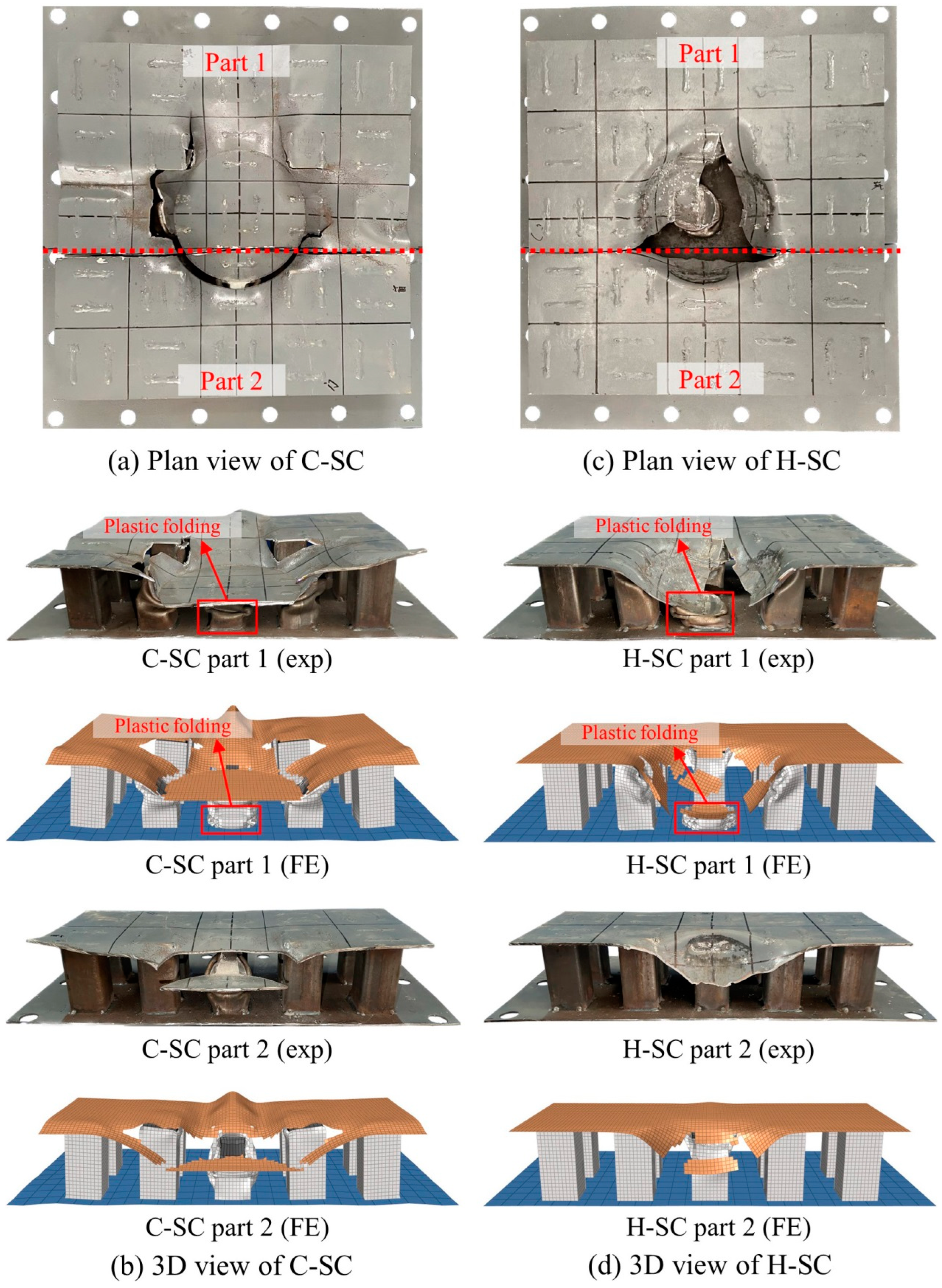
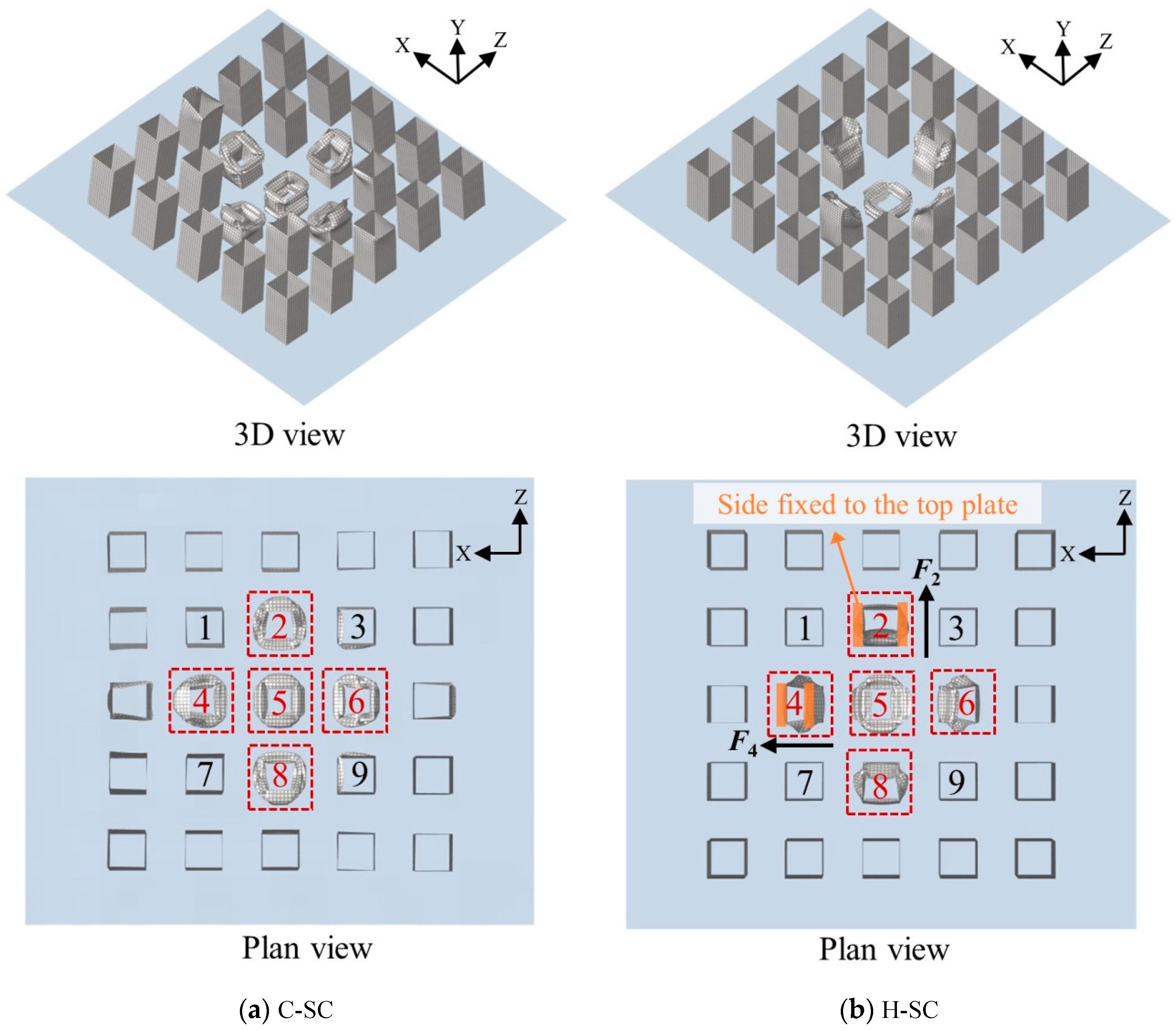
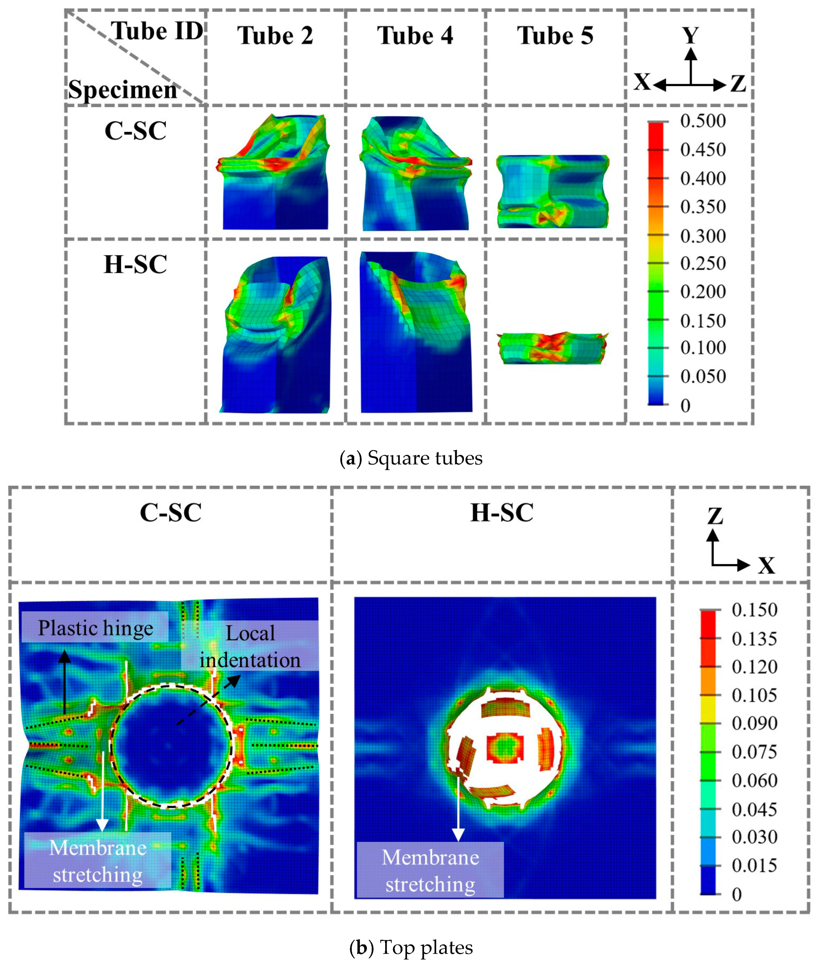
3.3. Deformation Modes

The permanent deformation modes of the C-SC and H-SC are presented in Figure 9. To more clearly reveal the deformation of the foam-filled tubes of these two specimens, the permanent deformations of the tubes from FE simulations are given in Figure 11. Only the tubes at the impact zone of the specimen (i.e., the five tubes highlighted in Figure 11) exhibit obvious plastic deformations. Tubes 2 and 8 almost share the same deformation mode under the impact of the cylindrical head and hemispherical head, respectively. In addition, the same deformation mode is observed for tubes 4 and 6. Therefore, there are three typical deformation modes being observed for the tubes (i.e., the deformation modes of tubes 2, 4 and 5) under impact loads. Figure 12a presents the effective plastic strain contours of tubes 2, 4 and 5 under the impact of two different hammer heads. In the case of the specimen C-SC, the apparent plastic collapse can be observed for tube 5, which belongs to the compact collapse mode, as mentioned in Section 3.2. Aside from the inward and outward folding of the tube wall, severe plastic deformation can be observed in the zones near the corner of tube 5. In addition, tubes 2 and 4 of the C-SC exhibit an almost identical deformation mode. An irregular plastic collapse mode appears in both of these tubes owing to oblique impact loading from the cylindrical hammer head. Compared to the sides of tubes 2 and 4 away from the hammer head, the other three sides exhibit more apparent collapse, as shown in Figure 11 and Figure 12a. For the specimen H-SC, tube 5 shares the same deformation mode as that of the C-SC but collapses more completely, i.e., the space between the folds for the tube 5 of the H-SC are closer than that of the C-SC. However, tubes 2 and 4 of the H-SC show quite different deformation modes compared to those of the C-SC due to the different shapes of the hammer heads. Specifically, the sides of tubes 2 and 4 near the hammer head exhibit an inward deformation, as presented in Figure 11 and Figure 12a, since these two tubes are subjected to lateral compression of the hemispherical hammer head. The inward deformation of these two tubes is significantly affected by the shape and size of the hemispherical hammer head. In addition, little plastic deformation can be observed on the sides of tubes 2 and 4 away from the hammer head, as shown in Figure 11, which is quite different from those of the C-SC. Furthermore, different deformation modes can be found between tubes 2 and 4 from the H-SC. This is caused by the different direction relationships between the constraint from the top plate and the lateral force from the hemispherical head for these two tubes, as shown in Figure 11b. To be specific, the sides of tube 2 that are constrained by the top plate are along the Z-axis direction and are perpendicular to the lateral force F2 from the hemispherical head, which is along the X-axis direction. However, a parallel relationship is seen for tube 4.
Figure 12b presents the effective plastic strain contours of the top plates of the C-SC and H-SC. It is evident that the plastic deformation zone that appeared at the top plate of the C-SC is larger than that of the H-SC. For the C-SC, a circular local indentation zone is formed under the impact load, and its shape and size are determined by that of the cylindrical head. The fracture of the top plate can be observed at the indentation zone along the edge of the cylindrical head, which may be caused by significant membrane stretching around the indentation zone and evident rotation of the plastic hinge at the edge of the indentation zone. In addition, some plastic hinge lines are formed at the edge zone of the top plate, which can enhance the energy absorption capacity. For the H-SC, the plastic deformation and fracture are concentrated in the impact zone of the top plate. High effective plastic strain values can be observed from elements within the impact zone, as shown in Figure 12b, which indicates that evident membrane stretching occurred in this zone and dissipated the impact energy effectively.

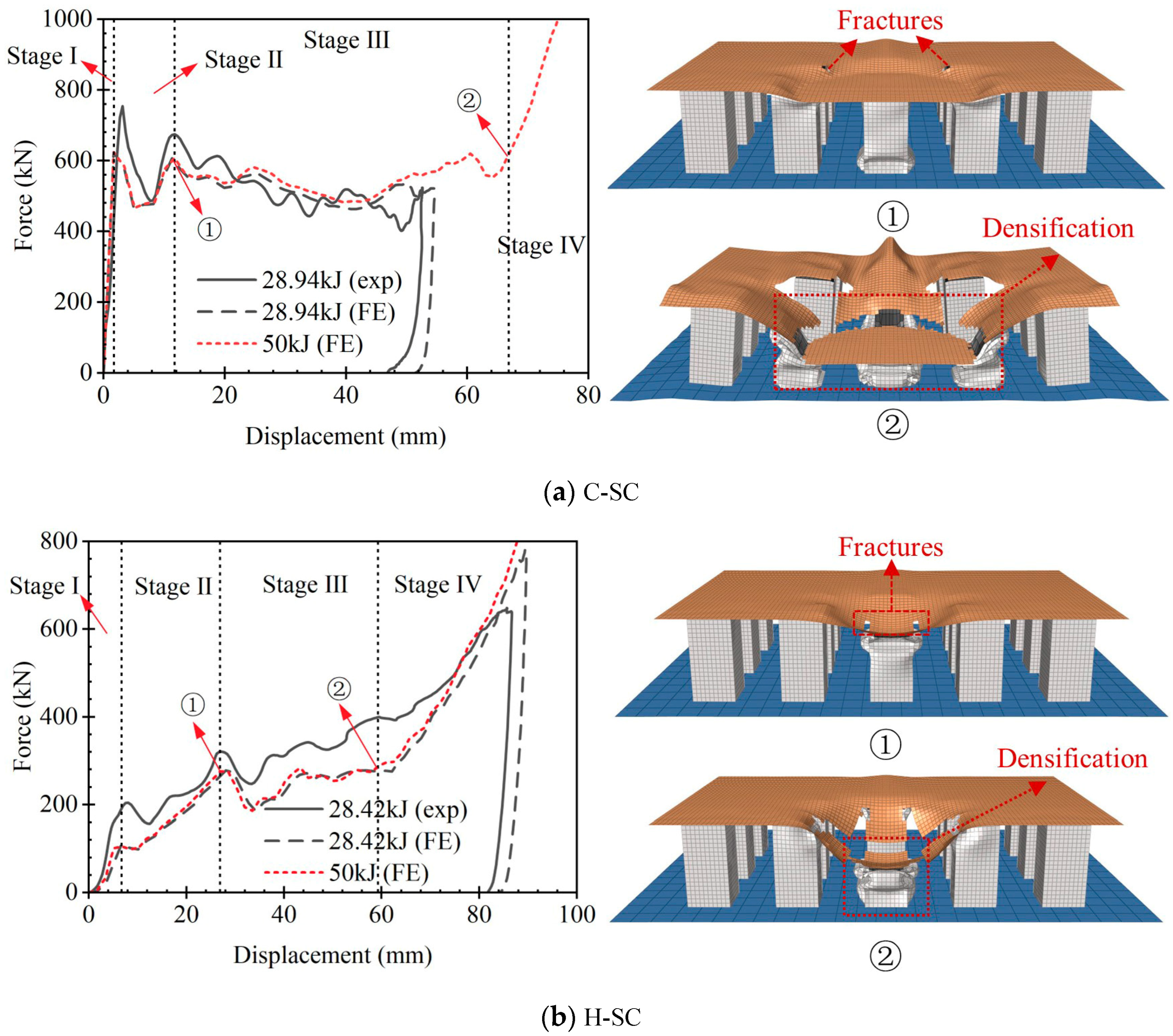
3.4. Force–Displacement Responses

The force–displacement curves of the C-SC and H-SC obtained from the experiment and FE simulation are shown in Figure 10. Apart from the impact energy used in the experiment, a higher impact energy (50 kJ) was adopted in the FE model to obtain the whole force–displacement responses of the specimens (i.e., the densifications of the specimens are reached) under the impact of the cylindrical and hemispherical hammer heads. The impact responses in both these two specimens can be classified into four stages based on the characteristics of their force–displacement curves. In the initial stage, the impact force of the C-SC increases rapidly with its displacement, as shown in Figure 10a. This is because the tubes under the cylindrical head (i.e., tubes 2, 4, 5, 6 and 8) are subjected to the impact of the hammer, while tubes under impact loads have a good axial bearing capacity before buckling. Entering stage II, a sharp decline can be observed in the impact force as buckling occurs on the tubes. When the displacement reaches 11.72 mm, fractures appear at the impact zone of the top plate, and the resistance of the top plate decreases. This leads to a decrease in the impact force, and then the force–displacement response enters stage III. Furthermore, the curve exhibits some fluctuations during stage III owing to the successive fracture of the top plate and progressive collapse of the tubes. Finally, the impact force increases rapidly and continuously, indicating that densification of the C-SC has been reached. In the case of the H-SC, the contact area between the specimen and hammer increases with further downward movement of the hammer, which is quite different from the C-SC. This results in a slow growth in the impact force at the initial stage. Subsequently, a continuous increase in the impact force is observed owing to the membrane stretching of the top plate, after the decrease caused by the buckling of the tubes. Entering stage III, the impact force presents a continuous decrease until displacement reaches 33.53 mm, when the top plate zone on tube 5 separates from the other part and membrane stretching failure occurs. With further impacting, the contact area between the hammer and the H-SC increases and more tubes are subjected to the impact loading. This leads to a slight rise in the impact force after the separation of the top plate zone on tube 5. Finally, a sharp increase in the impact force can be observed when the displacement exceeds 66.86 mm, and the densification and ultimate energy dissipation capacity of the H-SC are reached.

3.5. Energy Absorption Performances

Figure 13 illustrates the energy absorption in the various parts (i.e., the top plates, tubes and foam concrete blocks) of the C-SC and H-SC, which correspond to their densification displacements, respectively. The results indicate that the tubes are the main energy-absorbing part, accounting for more than half of the total EA. Given the excellent energy absorption performance of the tubes, the EA of each tube is obtained by FE simulations. The result shows that the majority of the energy dissipation of the tubes is the contribution of tubes 2, 4, 5, 6 and 8 (the numbering of the tubes is shown in Figure 14a), as these five tubes experience obvious plastic deformation. Figure 14b shows the EAs of tubes 2, 4, 5, 6 and 8 of the C-SC and H-SC. The EAs of these five tubes are similar for the C-SC, indicating that the irregular plastic collapse in tubes 2, 4, 6 and 8 can also effectively absorb the impact energy. Nevertheless, tube 5 exhibits an evidently higher EA than the other four tubes (i.e., tubes 2, 4, 6 and 8) for the H-SC. This suggests that the plastic folding in tube 5 is more effective than the inward plastic deformation of the other four tubes in energy dissipation. The top plate can also absorb the impact energy through the plastic hinges and membrane stretching, as well as fractures and the top plate of the C-SC, which has a higher EA than that of the H-SC owing to the larger plastic deformation zone. In addition, more than 10% of the impact energy is dissipated by the foam concrete.
The total EA in the C-SC is more than three times greater than that in the H-SC (the total EA in the C-SC and H-SC is calculated based on their own densification displacements, which are 34.97 kJ and 11.22 kJ, respectively). To ensure a fairer comparison of the energy absorption performances of these two specimens, the displacement of 59.28 mm, which is the lower value of their densification displacements (i.e., the densification displacement of the H-SC, xD = 59.28 mm), is selected to calculate EA. In this instance, the total EA in the C-SC is still 181.37% greater than that in the H-SC (i.e., the total EA of the C-SC is 31.56 kJ), which indicates that the C-SC exhibits better energy absorption performance compared to the H-SC. In general, the EA can be effectively improved by increasing the contact area between the impactor and sacrificial cladding.

3.6. Parametric Studies

Parameter studies were conducted in FE simulations to investigate the effects of the thickness ratio of the top plate to tube, width-to-thickness ratio of tube and impact location on the dynamic responses of the FCFST sacrificial cladding under the impact of the cylindrical and hemispherical heads. To ensure all specimens reached densification, an impact energy of 50 kJ was adopted by increasing the impact weight. In addition, the minimum densification displacement was chosen to calculate the EA under the impact of each hammer head in each parameter study for a fair comparison.

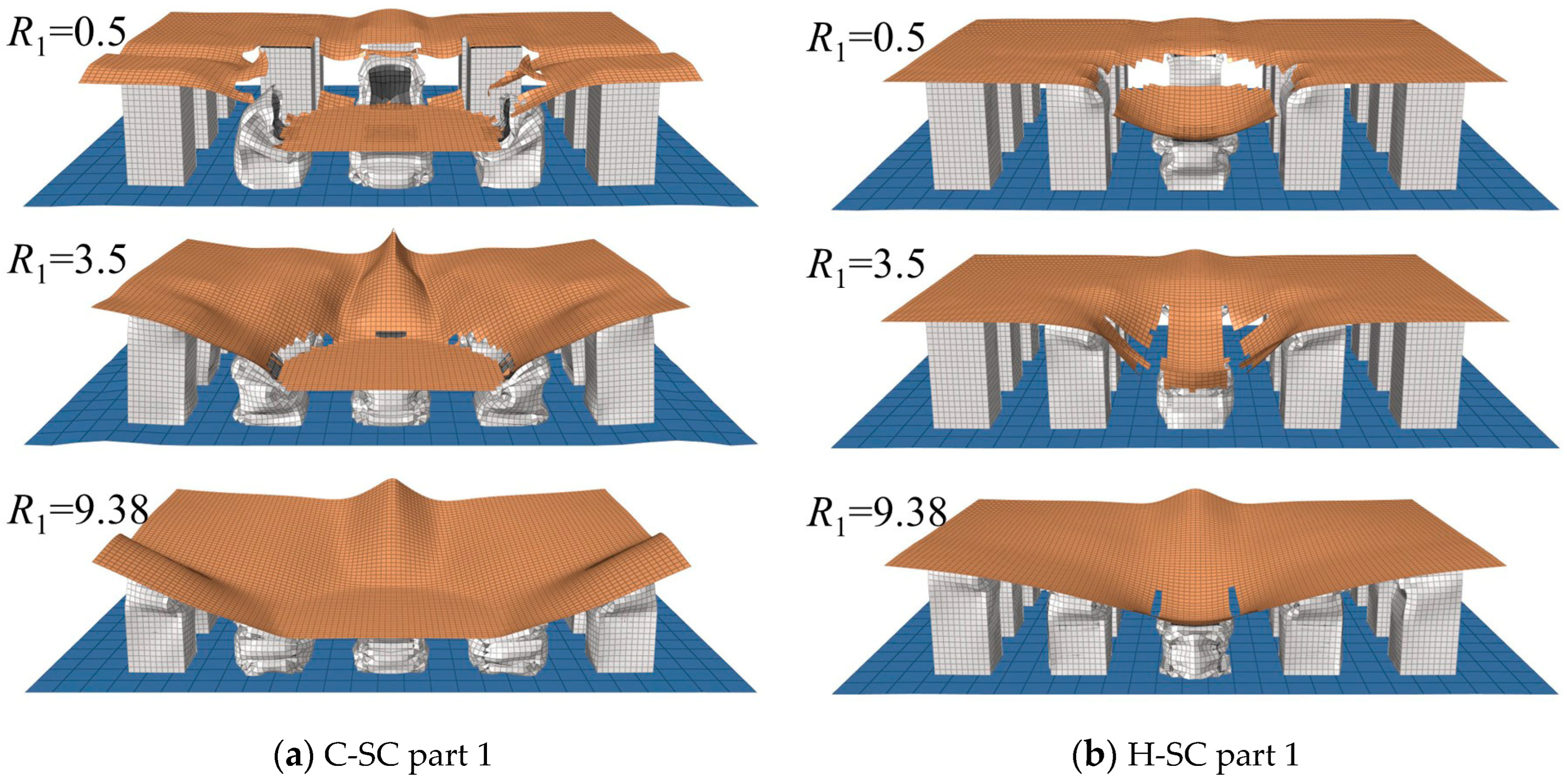
3.6.1. Effect of the Thickness Ratio of the Top Plate to Tube

Since the deformation mode and energy absorption performance of the sacrificial cladding may vary with the thickness ratio R1 (R1 = tp/tt) of the top plate to tube, the dynamic responses of specimens with various R1 values (i.e., R1 = 0.5, 1.0, 1.5, 2.0, 2.5, 3.5, 5.0 and 9.38) were numerically investigated. All specimens maintain the same total mass of the top plate and tubes.
The EAs and deformation modes of the claddings with various R1 values are shown in Figure 15 and Figure 16, respectively. The EA of the specimen C-SC generally exhibits a decreasing trend with the increase in the thickness ratio R1. Specifically, as the R1 increases from 0.5 to 1.5 and 9.38, the EA decreases by 6.46% and 42.34%, respectively. This decreasing trend is mainly caused by the decline in the EA of the tubes, which dissipates the majority of the impact energy. The reduction in the thickness of the tubes directly leads to a decrease in MCF as R1 increases [55], resulting in less energy dissipation of the tubes for the same densification displacement. Moreover, the EA of the top plate for the C-SC exhibits an increasing trend followed by a decrease as the R1 increases, and the highest value is reached when R1 is 3.5. This could be attributed to the change in its plastic deformation mode, as shown in Figure 16a. The premature fracture of the thinner top plate limits the development of its plastic deformation, which results in a 63.53% decline in the EA of the top plate as the R1 decreases from 3.5 to 0.5. However, the EA of the top plate decreases by 28.14% on increasing the R1 from 3.5 to 9.38. This is caused by the reduction in the plastic deformation of the top plate in the C-SC. As the R1 increases, the foam concrete blocks experience more compressive deformation, resulting in a continuous increase in their EA. With regard to the specimen H-SC, the EA shows a stable tendency after an initial decrease with the increase in R1. The tubes and top plate in the H-SC exhibit similar trends with those of the C-SC, but their EAs decrease slightly as the R1 increases from 3.5 to 9.38. In addition, the major impact energy is dissipated by the top plate when the R1 exceeds 2, which is different from the C-SC. It is noted that fracture of the top plate can be observed in the H-SC but not in the C-SC when R1 reaches 9.38. This indicates that the fracture may occur more easily for the smaller contact area between the cladding and impactor, with the same drop weight and velocity. In general, decreasing the thickness ratio R1 can enhance the energy absorption performance of the FCFST sacrificial cladding.

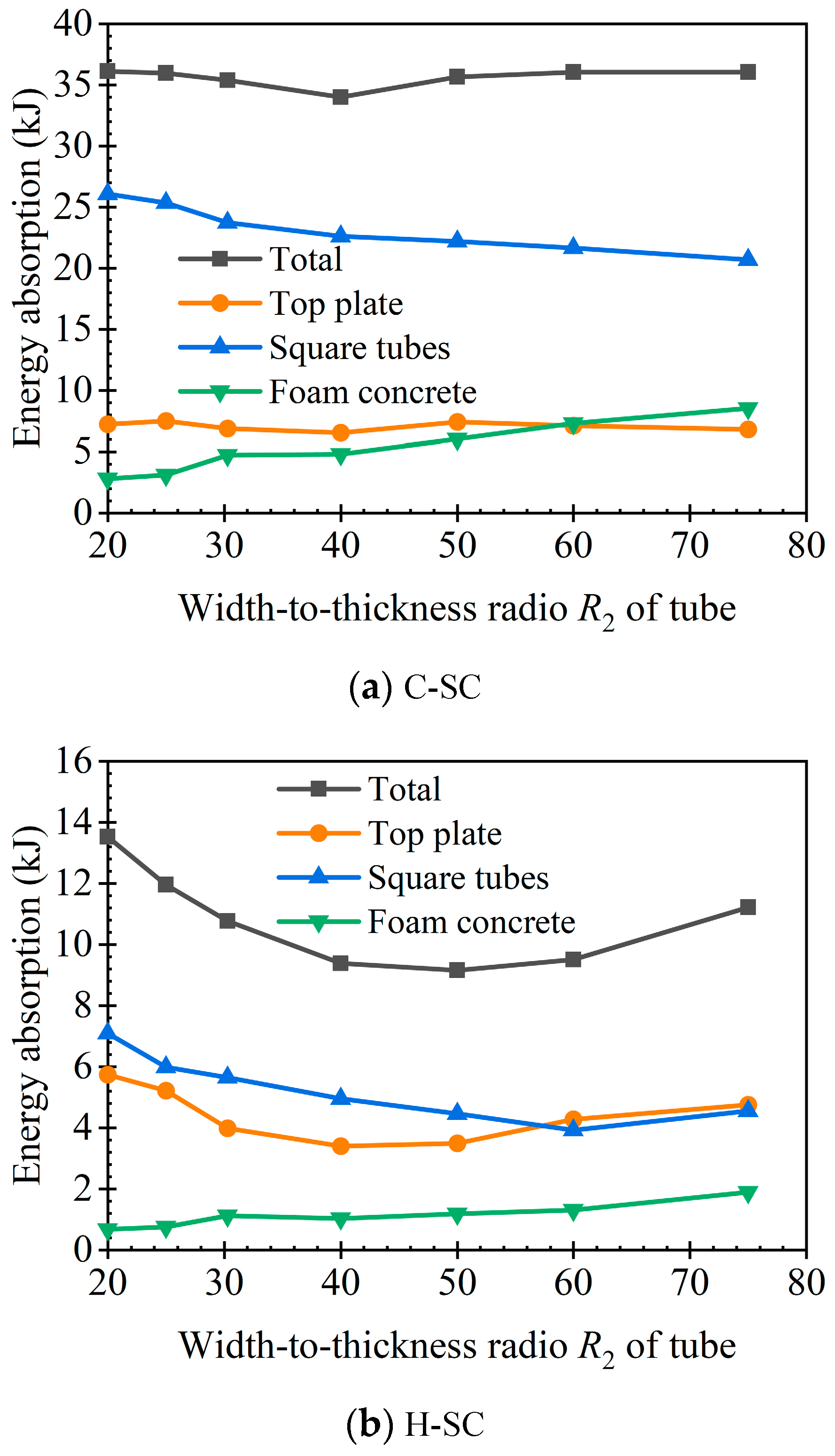
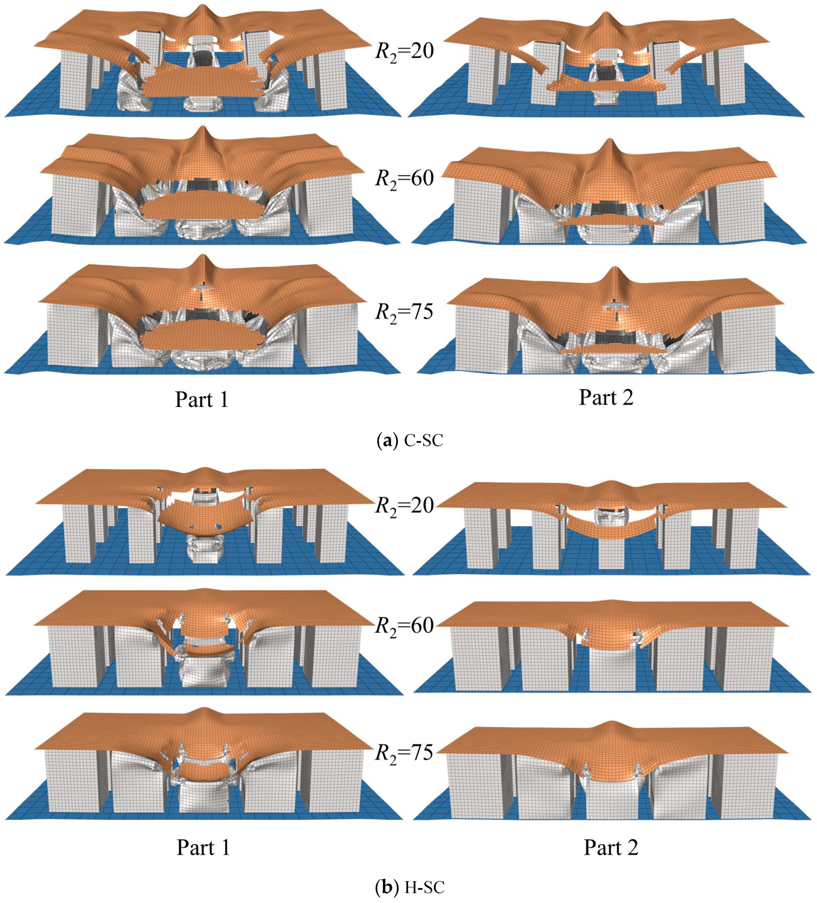
3.6.2. Effect of the Width-to-Thickness Ratio of the Tube

Since the deformation mode and energy absorption performance of the sacrificial cladding may vary with the width-to-thickness ratio, R2 (R2 = c/tt), of the tube, the dynamic responses of the specimens with various R2 values of 20, 25, 30, 40, 50, 60 and 75 were studied by FE simulation. The total mass of 25 square tubes is kept constant for all specimens, and the tubes are always filled with foam concrete.
The EAs in the sacrificial claddings with various width-to-thickness ratio R2 values are compared in Figure 17. The classical deformation modes in the specimens C-SC and H-SC with an R2 of 20, 60 and 75 are illustrated in Figure 18. The EA in the C-SC is not apparently affected by the variation in the R2. As shown in Figure 17a, the maximum value of the EA is reached when the R2 is 20, and it is only 6.21% larger than the minimum value when the R2 is 40. On the one hand, the thickness of the tube has a more significant effect than its width on the MCF when it deforms with the manner of plastic folding [55]. This leads to a reduction in the MCF of the tubes as R2 increases; thus, its EA exhibits a decreasing trend. On the other hand, more foam concrete is crushed, resulting in a steady rise in its EA with the increase in the R2. Moreover, the foam concrete dissipates more impact energy than the top plate when the R2 exceeds 60. As for the specimen H-SC, increasing the R2 is found to result in the trend of an initial decrease and then an increase in the EA, and the same trend can be observed in the EAs of its top plate and tubes. Figure 18b shows that the plastic deformation of the tubes at the impact zone increases as R2 increases from 60 to 75, which may be evidence for the slight rise in the EA of the tubes. In addition, the EA of the foam concrete gradually rises with the increase in the R2, and it keeps the same tendency with that of the C-SC. The above results indicate that increasing the R2 will lead to an increase in the EA in foam concrete.

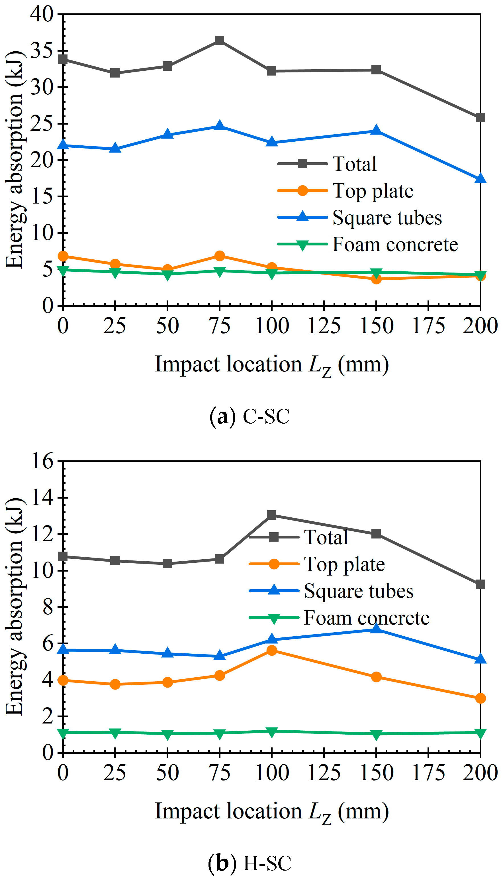
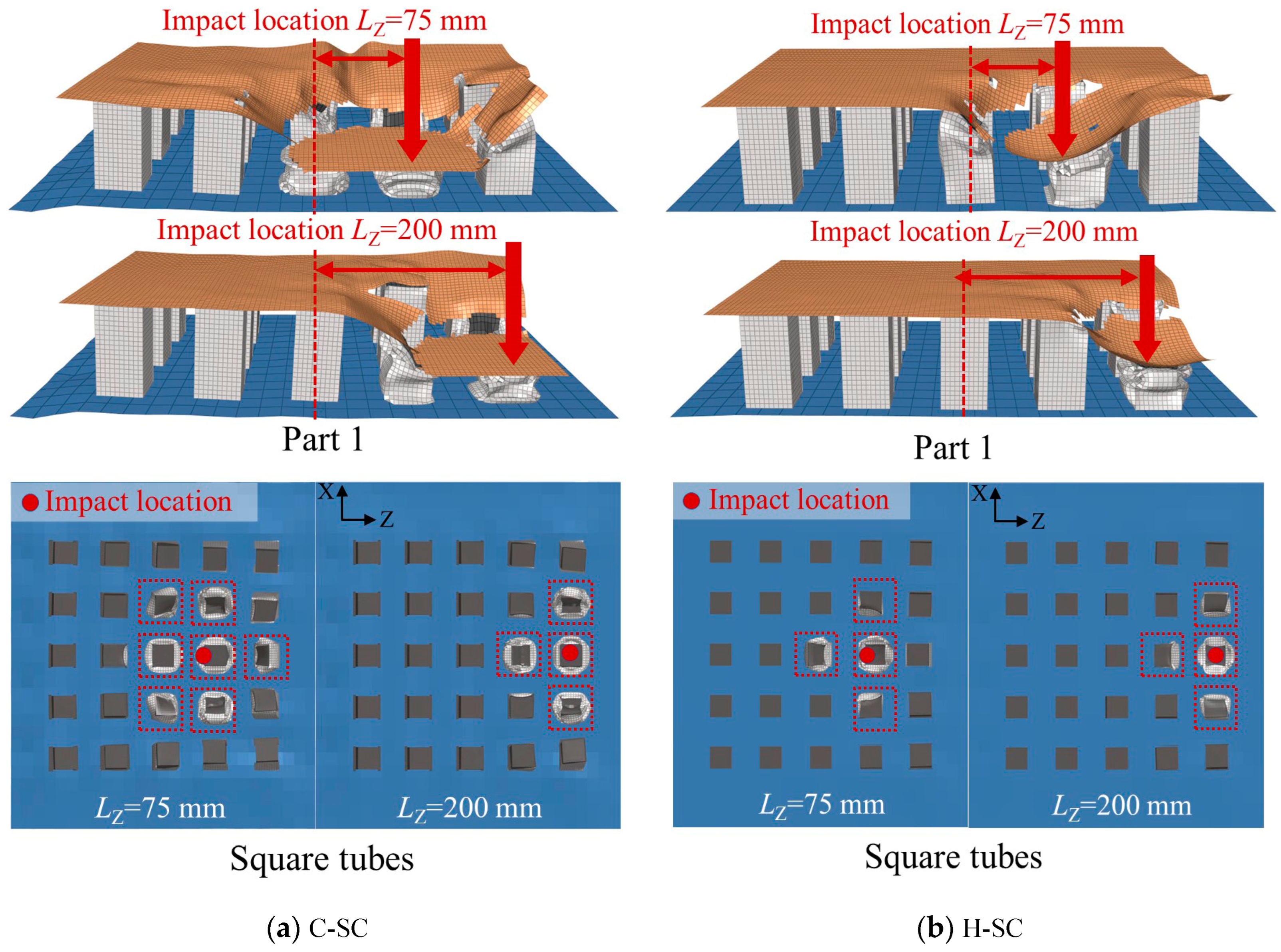
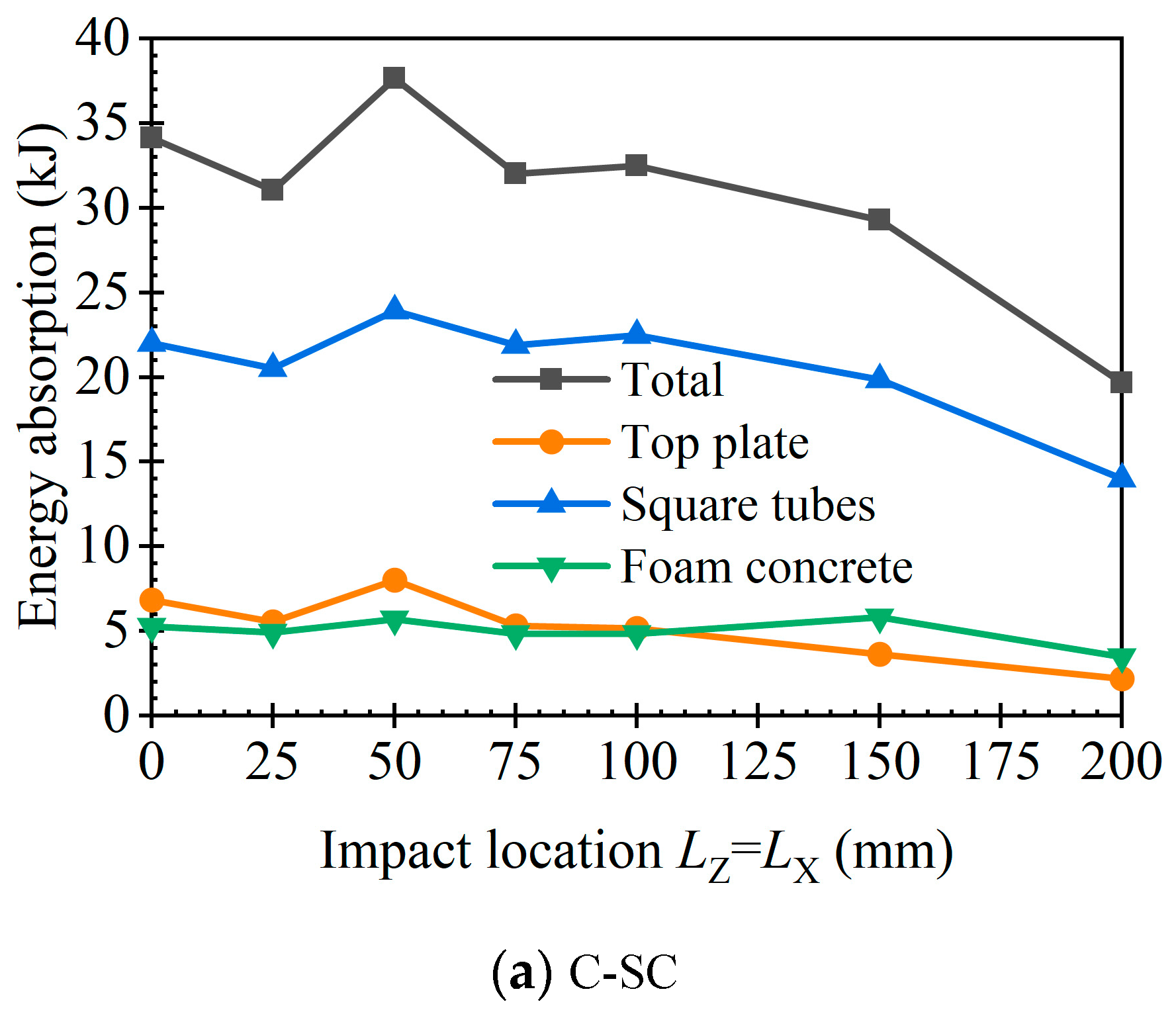
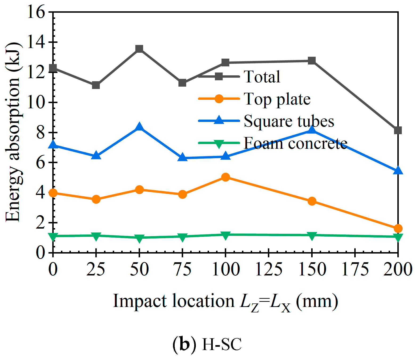
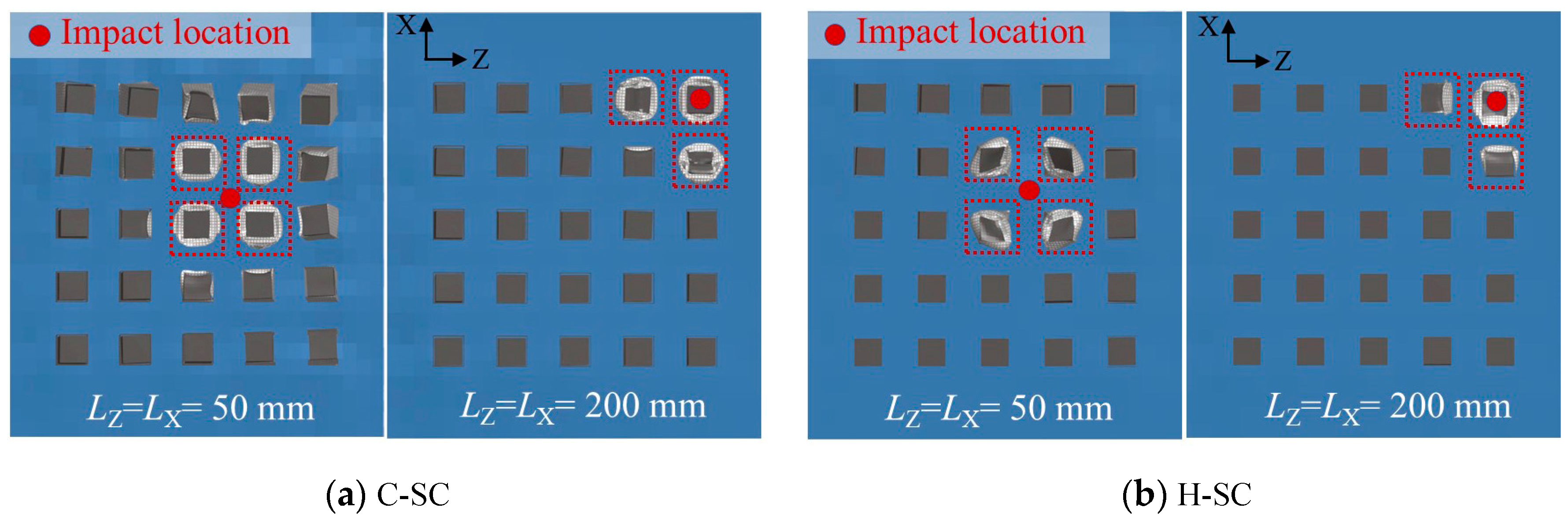
3.6.3. Effect of Impact Location

Since the deformation mode and energy absorption performance of the sacrificial cladding may vary with the impact location of the hammer, the effect of the impact location was studied by FE simulation. In detail, the impact responses of specimens under various impact locations were simulated (i.e., LZ = 0, 25, 50, 75, 100, 150 and 200 mm, LZ = LX = 0, 25, 50, 75, 100, 150 and 200 mm, LZ and LX are the distances between the impact location and the centre of the specimen along the Z-axis direction and X-axis direction, respectively).
Figure 19 illustrates the EAs in claddings under various impact locations along the Z-axis direction (LZ). The typical deformation modes of the C-SC and H-SC under various impact locations (LZ = 75 and 200 mm) are compared in Figure 20. As the LZ increases, the EA in C-SC does not show a marked decline until LZ reaches 200 mm. In detail, the energy absorption performance in the C-SC is significantly affected by the EA of its tubes, and almost the same tendency can be found in the EAs between the specimen and the tubes. When LZ is 200 mm, the number of square tubes experiencing evident plastic deformation is reduced compared to other impact locations, as shown in Figure 20a. This results in a greater than 25% decline in the EA compared to the impact location LZ = 150 mm. The EA in the H-SC exhibits the same result as that of the C-SC, i.e., a significant decrease is observed until LZ is 200 mm. However, the energy absorption proportion of the top plate for the H-SC is higher than that for the C-SC, which indicates that the energy absorption performance of the top plate significantly affects the EA of the H-SC. For instance, the decrease in the energy dissipation of the top plate directly results in a reduction in the EA of H-SC as LZ increases from 100 to 150 mm, though the EA of the tubes slightly increases. Furthermore, the EAs and deformation modes of the tubes of claddings under various impact locations along the diagonal direction between the X-axis and Z-axis are compared in Figure 21 and Figure 22, respectively. It is evident that the EAs have the same results as those under various impact locations along the Z-axis, i.e., the EA decreases significantly when the impact location is far from the centre of the specimen. In addition, significant plastic deformation can be found among all four tubes within the impact zone when LZ and LX are 50 mm, as shown in Figure 22. This leads to the highest EAs of the specimen and tubes. In general, the FCFST sacrificial cladding can dissipate impact energy effectively unless the impact location is close to its edge.

4. Conclusions

In this paper, a new FCFST sacrificial cladding was developed for dissipating impact energy. The impact behaviour and energy absorption performance of the FCFST sacrificial cladding were investigated by drop hammer impact experiments and FE simulations. Based on the above experimental and numerical results, the conclusions can be summarised as follows:
(1)
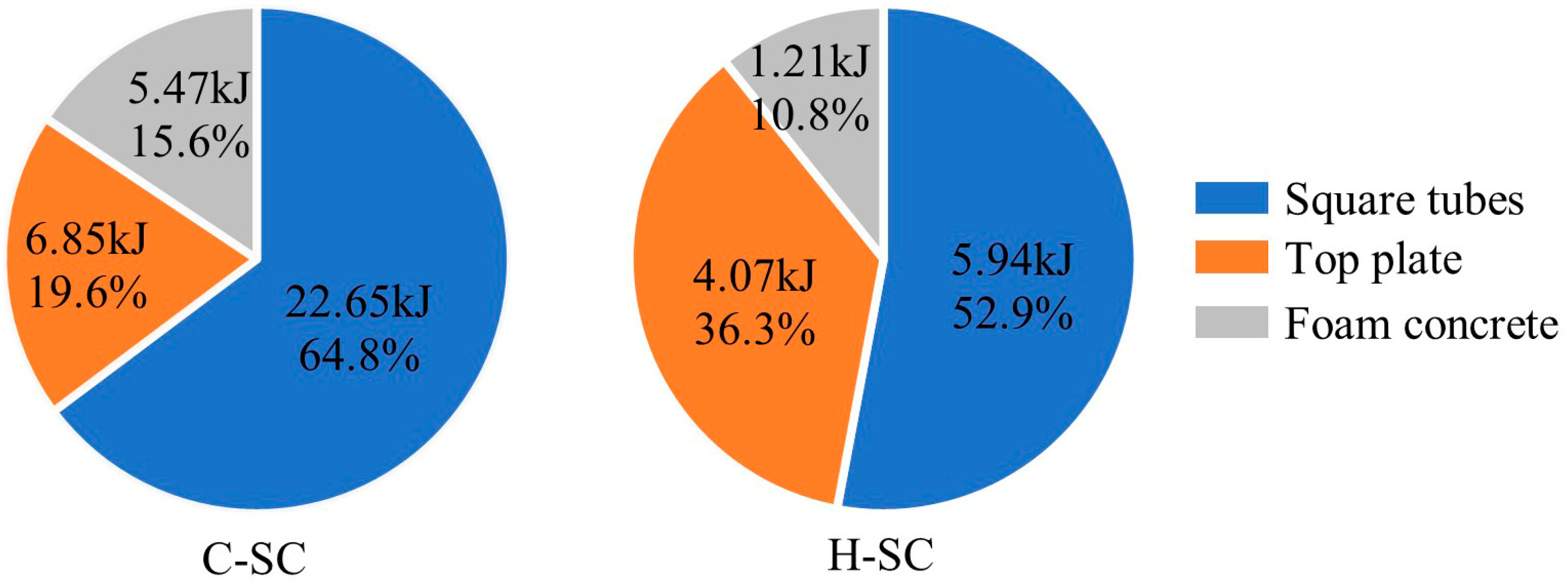
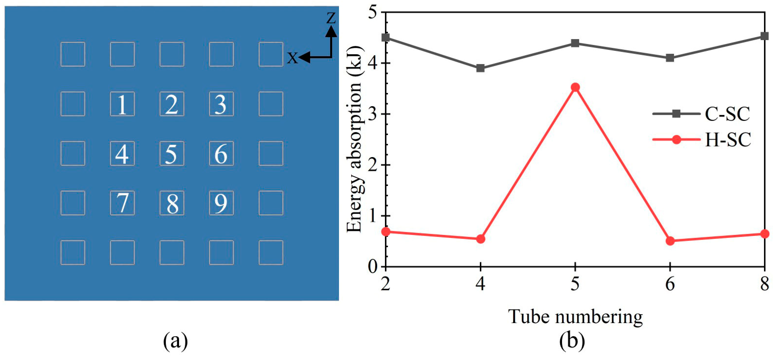
The tube filled with foam concrete is the main energy-absorbing part of the FCFST sacrificial cladding. Under the impact of the drop hammer, five tubes at the impact zone of the sacrificial cladding exhibit obvious plastic deformation, and three deformation modes can be observed in these tubes. The tube that experiences irregular plastic folding can also dissipate impact energy as effectively as the tube with a compact collapse mode.
(2)
Four stages can be identified in impact responses of the FCFST sacrificial cladding according to its deformation process and characteristics of the force–displacement curves. The fracture of the top plate leads to failure of its membrane stretching; thus, the impact force of the sacrificial cladding decreases. In addition, the premature fracture of a thinner top plate is found to limit the development of its plastic deformation, which leads to lower energy absorption under impact loads.
(3)
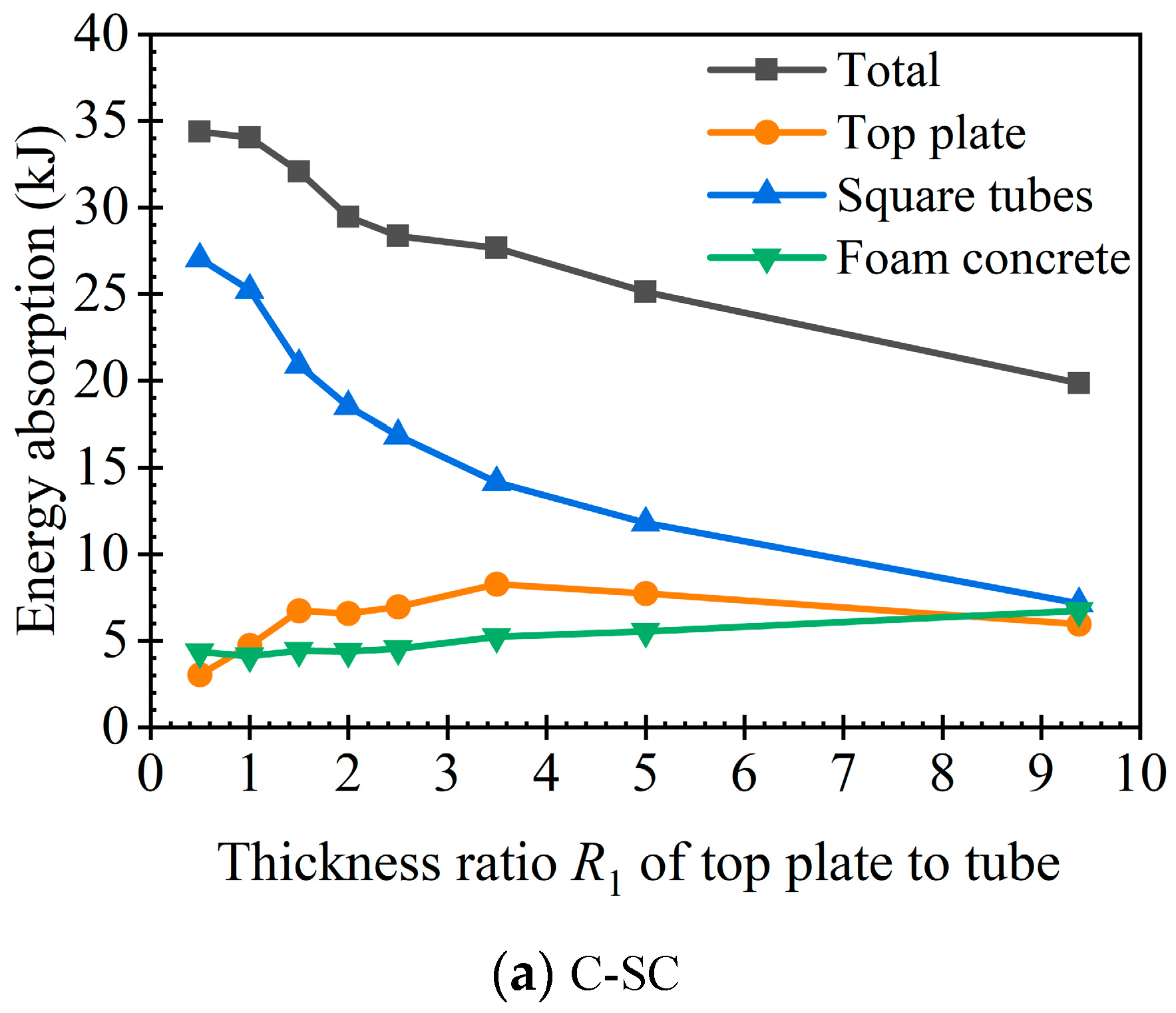
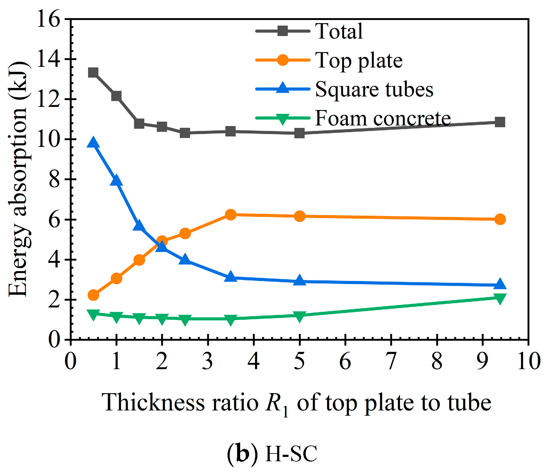
The specimen subjected to the impact of the cylindrical head exhibited better energy absorption performance than that subjected to the impact of the hemispherical head. This indicates that the energy absorption can be improved effectively by increasing the contact area between the impactor and the sacrificial cladding. Decreasing the thickness ratio of the top plate to tube can also lead to an improvement in the energy absorption of the sacrificial cladding when the total mass of top plate and tubes are constant. Furthermore, the impact location is found to have insignificant effect on the energy absorption of the sacrificial cladding unless it is close to the edge.

Author Contributions

Conceptualization, Y.W. and X.Z.; Methodology, L.G. and Y.W.; Software, L.G.; Validation, L.G.; Formal analysis, L.G.; Resources, Y.W.; Writing—original draft, L.G.; Writing—review & editing, Y.W. and X.Z.; Supervision, Y.W. and X.Z.; Funding acquisition, Y.W. All authors have read and agreed to the published version of the manuscript.

Funding

The research presented in this paper is financially supported by the National Natural Science Foundation of China (Grant No. 52278166), the Natural Science Foundation of Heilongjiang Province of China (Grant No. YQ2022E035), the Fundamental Research Funds for the Central Universities (Grant No. FRFCU5710051919) and the Heilongjiang Postdoctoral Science Foundation (Grant No. LBH-Q21099 and LBH-TZ1014).

Data Availability Statement

The data presented in this study are available on request from the corresponding author.

Conflicts of Interest

The authors declare no conflict of interest.

References

  1. Rov, T.; Matsagar, V. Probabilistic framework for failure investigation of reinforced concrete wall panel under dynamic blast loads. Eng. Fail. Anal. 2021, 125, 105368. [Google Scholar]
  2. Sohel, K.M.A.; Al-Jabri, K.; Al-Abri, A.H.S. Behavior and design of reinforced concrete building columns subjected to low-velocity car impact. Structures 2020, 26, 601–616. [Google Scholar] [CrossRef]
  3. Ali Hadianfard, M.; Malekpour, S.; Momeni, M. Reliability analysis of H-section steel columns under blast loading. Struct. Saf. 2018, 75, 45–56. [Google Scholar] [CrossRef]
  4. Momeni, M.; Ali Hadianfard, M.; Bedon, C.; Baghlani, A. Damage evaluation of H-section steel columns under impulsive blast loads via gene expression programming. Eng. Struct. 2020, 219, 110909. [Google Scholar] [CrossRef]
  5. Momeni, M.; Bedon, C.; Ali Hadianfard, M.; Baghlani, A. An Efficient Reliability-Based Approach for Evaluating Safe Scaled Distance of Steel Columns under Dynamic Blast Loads. Buildings 2021, 11, 606. [Google Scholar] [CrossRef]
  6. Wang, Y.; Zhai, X.; Liu, S.; Lu, J.; Zhou, H. Energy absorption performance of a new circular–triangular nested tube and its application as sacrificial cladding. Thin-Walled Struct. 2020, 157, 106992. [Google Scholar] [CrossRef]
  7. Chung, K.; Yuen, S.; Cunliffe, G.; Du Plessis, M.C. Blast response of cladding sandwich panels with tubular cores. Int. J. Impact Eng. 2017, 110, 266–278. [Google Scholar]
  8. Magliaro, J.; Altenhof, W.; Alpas Ahmet, T. A review of advanced materials, structures and deformation modes for adaptive energy dissipation and structural crashworthiness. Thin-Walled Struct. 2022, 180, 109808. [Google Scholar] [CrossRef]
  9. Xu, F.; Zhang, X.; Zhang, H. A review on functionally graded structures and materials for energy absorption. Eng. Struct. 2018, 171, 309–325. [Google Scholar] [CrossRef]
  10. Baroutaji, A.; Arjunan, A.; Stanford, M.; Robinson, J.; Olabi, A.G. Deformation and energy absorption of additively manufactured functionally graded thickness thin-walled circular tubes under lateral crushing. Eng. Struct. 2021, 226, 111324. [Google Scholar] [CrossRef]
  11. Reddy, T.Y.; Reid, S.R. Lateral compression of tubes and tube-systems with side constraints. Int. J. Mech. Sci. 1979, 21, 187–199. [Google Scholar] [CrossRef]
  12. Alghamdi, A.A.A. Collapsible impact energy absorbers: An overview. Thin-Walled Struct. 2001, 39, 189–213. [Google Scholar] [CrossRef]
  13. Baroutaji, A.; Sajjia, M.; Olabi, A.G. On the crashworthiness performance of thin-walled energy absorbers: Recent advances and future developments. Thin-Walled Struct. 2017, 118, 137–163. [Google Scholar] [CrossRef] [Green Version]
  14. Alexander, B.J.M. An approximate analysis of the collapse of thin cylindrical shells under axial loading. Q. J. Mech. Appl. Math. 1960, 13, 10–15. [Google Scholar] [CrossRef]
  15. Abramowicz, W.; Jones, N. Dynamic progressive buckling of circular and square tubes. Int. J. Impact Eng. 1986, 4, 243–270. [Google Scholar] [CrossRef]
  16. Wierzbicki, T.; Abramowicz, W. On the crushing mechanics of thin-walled structures. J. Appl. Mech. 1983, 50, 727–734. [Google Scholar] [CrossRef]
  17. Guillow, S.R.; Lu, G.; Grzebieta, R.H. Quasi-static axial compression of thin-walled circular aluminium tubes. Int. J. Mech. Sci. 2001, 43, 2103–2123. [Google Scholar] [CrossRef]
  18. Reid, S.R. plastic deformation mechanisms in axially compressed metal tubes used as impact energy absorbers. Int. J. Mech. Sci. 1993, 35, 1035–1052. [Google Scholar] [CrossRef]
  19. Abramowicz, W.; Jones, N. Transition from initial global bending to progressive buckling of tubes loaded statically and dynamically. Int. J. Impact Eng. 1997, 19, 415–437. [Google Scholar] [CrossRef]
  20. Santosa, S.P.; Wierzbicki, T.; Hanssen, A.G.; Langseth, M. Experimental and numerical studies of foam-filled sections. Int. J. Impact Eng. 2000, 24, 509–534. [Google Scholar] [CrossRef]
  21. Reid, S.R.; Reddy, T.Y.; Gray, M.D. Static and dynamic axial crushing of foam-filled sheet metal tubes. Int. J. Mech. Sci. 1986, 28, 295–322. [Google Scholar] [CrossRef]
  22. Seitzberger, M.; Rannerstorfer, F.G.; Degischer, H.P.; Gradinger, R. Crushing of axially compressed steel tubes filled with aluminium foam. Acta Mech. 1997, 125, 93–105. [Google Scholar] [CrossRef]
  23. Zhou, H.; Zhang, X.; Wang, X.; Zhang, H.; Song, T. Improving energy absorption capacity of foam concrete with gradient and layered architecture. Constr. Build. Mater. 2022, 319, 126140. [Google Scholar] [CrossRef]
  24. Zhou, H.; Zhang, X.; Wang, X.; Wang, Y.; Zhao, T. Response of foam concrete-filled aluminum honeycombs subject to quasi-static and dynamic compression. Compos. Struct. 2020, 239, 112025. [Google Scholar] [CrossRef]
  25. Zhang, C.; Tan, X.; Chen, W.; Tian, H.; Wu, G.; Zhao, W.; Gao, H.; Jia, Z. Investigation on the deformation and energy dissipation behaviors for foamed concrete filled polyethylene pipe under quasi-static axial compression. Constr. Build. Mater. 2023, 370, 130557. [Google Scholar] [CrossRef]
  26. Wang, Y.; Zhou, Z.; Zhai, X.; Zhou, H.; Zhao, P. Impact responses of steel–concrete–steel sandwich panels with interlocked angle connectors: Experimental and numerical studies. Thin-Walled Struct. 2023, 188, 110832. [Google Scholar] [CrossRef]
  27. Chau, N.; Dao, T.P.; Nguyen, V. An efficient hybrid approach of finite element method, artificial neural network -based multiobjective genetic algorithm for computational optimization of a linear compliant mechanism of nanoindentation tester. Math. Probl. Eng. 2018, 2018, 7070868. [Google Scholar] [CrossRef]
  28. Wang, C.N.; Yang, F.C.; Nguyen, V.; Vo, N. CFD analysis and optimum design for a centrifugal pump using an effectively artificial intelligent algorithm. Micromachines 2022, 13, 1208. [Google Scholar] [CrossRef]
  29. Liao, W.; Huang, Z.; Sun, H.; Huang, X.; Gu, Y.; Chen, W.; Zhang, Z.; Kan, J. Numerical investigation of cylinder vortex-induced vibration with downstream plate for vibration suppression and energy harvesting. Energy 2023, 281, 128264. [Google Scholar] [CrossRef]
  30. Meng, L.; Zhai, X.; Wang, Y. Investigation on lateral impact resistant performance of aluminum foam-filled 6082-T6 aluminum alloy circular tubes: Experimental and numerical study. Thin-Walled Struct. 2023, 188, 110816. [Google Scholar] [CrossRef]
  31. Gao, H.; Wang, Y.; Zhai, X.; Zhou, H. Response of multi-cell steel–concrete–steel sandwich panels impacted by a hemi-spherical head: Experimental and numerical studies. Thin-Walled Struct. 2023, 185, 110643. [Google Scholar] [CrossRef]
  32. Zhou, H.; Zhang, X.; Wang, X.; Du, X.; Yu, S.; Wang, Y.; Jiang, J. Protection effectiveness of sacrificial cladding for near-field blast mitigation. Int. J. Impact Eng. 2022, 170, 104361. [Google Scholar] [CrossRef]
  33. Van Paepegem, W.; Palanivelu, S.; Degrieck, J.; Vantomme, J.; Reymen, B.; Kakogiannis, D.; Van Hemelrijck, D.; Wastiels, J. Blast performance of a sacrificial cladding with composite tubes for protection of civil engineering structures. Compos. Part B 2014, 65, 131–146. [Google Scholar] [CrossRef] [Green Version]
  34. Qi, C.; Remennikov, A.; Pei, L.Z.; Yang, S.; Yu, Z.H.; Ngo, T. Impact and close-in blast response of auxetic honeycomb-cored sandwich panels: Experimental tests and numerical simulations. Compos. Struct. 2017, 180, 161–178. [Google Scholar] [CrossRef]
  35. Karsandik, Y.; Sabuncuoglu, B.; Yildirim, B.; Silberschmidt, V.V. Impact behavior of sandwich composites for aviation applications: A review. Compos. Struct. 2023, 314, 116941. [Google Scholar] [CrossRef]
  36. Faidzi, M.K.; Abdullah, S.; Abdullah, M.F.; Azman, A.H.; Hui, D.; Singh, S.S.K. Review of current trends for metal-based sandwich panel: Failure mechanisms and their contribution factors. Eng. Fail. Anal. 2021, 123, 105302. [Google Scholar] [CrossRef]
  37. Mocian, O.; Constantinescu, D.M.; Sandu, M.; Sorohan, Ș.; Roșu, D.; Feuchter, M. Impact response of sandwich panels with polyurethane and polystyrene core and composite facesheets. Mater. Today Proc. 2019, 12, 192–199. [Google Scholar] [CrossRef]
  38. Mocian, O.; Constantinescu, D.M.; Sandu, M.; Sorohan, Ș. Experimental and numerical analyses of the impact response of lightweight sandwich panels. Mater. Today Proc. 2018, 5, 26634–26641. [Google Scholar] [CrossRef]
  39. Huo, X.; Liu, H.; Luo, Q.; Sun, G.; Li, Q. On low-velocity impact response of foam-core sandwich panels. Int. J. Mech. Sci. 2020, 181, 105681. [Google Scholar] [CrossRef]
  40. Kurșun, A.; Șenel, M.; Enginsoy, H.M.; Bayraktar, E. Effect of impactor shapes on the low velocity impact damage of sandwich composite plate: Experimental study and modelling. Compos. Part B 2016, 86, 143–151. [Google Scholar] [CrossRef]
  41. Wang, J.; Waas, A.M.; Wang, H. Experimental and numerical study on the low-velocity impact behavior of foam-core sandwich panels. Compos. Struct. 2013, 96, 298–311. [Google Scholar] [CrossRef]
  42. Qin, Q.; Chen, S.; Li, K.; Jiang, M.; Cui, T.; Zhang, J. Structural impact damage of metal honeycomb sandwich plates. Compos. Struct. 2020, 252, 112719. [Google Scholar] [CrossRef]
  43. Xie, S.; Jing, K.; Zhou, H.; Liu, X. Mechanical properties of Nomex honeycomb sandwich panels under dynamic impact. Compos. Struct. 2020, 235, 111814. [Google Scholar] [CrossRef]
  44. Elangovan, H.; Rajamohan, V. Dynamic characterization of tapered composite sandwich plate with honeycomb core: Numerical and experimental investigations. Thin-Walled Struct. 2022, 178, 109515. [Google Scholar] [CrossRef]
  45. Liu, J.; Chen, W.; Hao, H.; Wang, Z. Numerical study of low-speed impact response of sandwich panel with tube filled honeycomb core. Compos. Struct. 2019, 220, 736–748. [Google Scholar] [CrossRef]
  46. Zhang, D.; Fei, Q.; Zhang, P. Drop-weight impact behavior of honeycomb sandwich panels under a spherical impactor. Compos. Struct. 2017, 168, 633–645. [Google Scholar] [CrossRef]
  47. Lu, J.; Wang, Y.; Zhai, X.; Zhi, X.; Zhou, H. Impact behavior of a cladding sandwich panel with aluminum foam-filled tubular cores. Thin-Walled Struct. 2021, 169, 108459. [Google Scholar] [CrossRef]
  48. Cheng, W.; Bin, X.; Chung Kim Yuen, S. Numerical analysis of cladding sandwich panels with tubular cores subjected to uniform blast load. Int. J. Impact Eng. 2019, 133, 103345. [Google Scholar]
  49. Xia, Z.; Wang, X.; Fan, H.; Li, Y.; Jin, F. Blast resistance of metallic tube-core sandwich panels. Int. J. Impact Eng. 2016, 97, 10–28. [Google Scholar] [CrossRef]
  50. Theobald, M.D.; Nurick, G.N. Numerical investigation of the response of sandwich-type panels using thin-walled tubes subjected to blast loads. Int. J. Impact Eng. 2007, 34, 134–156. [Google Scholar] [CrossRef]
  51. Zhou, H.; Fan, J.; Wang, X.; Ma, G.; Yu, S.; Wang, Y. Protection performance of sacrificial cladding with foam concrete filled aluminum tubes under blast loading. Int. J. Impact Eng. 2023, 179, 104633. [Google Scholar] [CrossRef]
  52. Yan, C.; Wang, Y.; Zhai, X. Low velocity impact performance of curved steel-concrete-steel sandwich shells with bolt connectors. Thin-Walled Struct. 2020, 150, 106672. [Google Scholar] [CrossRef]
  53. Wang, W.D.; Zheng, L.; Xian, W. Performance of the CFST column to composite beam connection under static and impact loads. J. Constr. Steel Res. 2022, 198, 107567. [Google Scholar] [CrossRef]
  54. Wang, Y.; Zhang, R.; Liu, S.; Zhai, X.; Zhi, X. Energy absorption behaviour of an aluminium foam-filled circular-triangular nested tube energy absorber under impact loading. Structures 2021, 34, 95–104. [Google Scholar] [CrossRef]
  55. Lu, G.; Yu, T.X. Energy Absorption of Structures and Materials; Elsevier: Cambridge, UK, 2003; pp. 162–163, 168, 171. [Google Scholar]
Figure 1. Three dimensional schematic view of the foam concrete-filled square tubes (FCFST) sacrificial cladding.
Buildings 13 01774 g001
Figure 2. Flowchart of the study process.
Buildings 13 01774 g002
Figure 3. Fabrication process of the FCFST sacrificial cladding. (a) Slitting slot holes and drilling bolt holes; (b) fixing of square tubes; (c) filling of foam concrete cuboids; and (d) plug welding between flat plates and square tubes.
Buildings 13 01774 g003
Figure 4. Drop hammer impact experiment setup.
Buildings 13 01774 g004
Figure 5. Finite element (FE) model of the FCFST sacrificial cladding subjected to the impact of the cylindrical head.
Buildings 13 01774 g005
Figure 6. Mesh sensitivity analysis of the FCFST sacrificial cladding.
Buildings 13 01774 g006
Figure 7. Stress–strain curves defined in the FE model. (a) Stress–strain curves of mild steel. (b) Stress–strain curve of foam concrete.
Buildings 13 01774 g007
Figure 8. Determination of the densification displacement xD.
Buildings 13 01774 g008
Figure 9. Comparation of the permanent deformation modes of the FCFST sacrificial cladding from the experiment and FE simulation.
Buildings 13 01774 g009
Figure 10. Force–displacement curves of the FCFST sacrificial cladding.
Buildings 13 01774 g010
Figure 11. Final deformation of the square tubes.
Buildings 13 01774 g011
Figure 12. Effective plastic strain contours of the C-SC and H-SC.
Buildings 13 01774 g012
Figure 13. Energy absorption in various parts of the FCFST sacrificial cladding.
Buildings 13 01774 g013
Figure 14. Energy dissipation of different tubes of the FCFST sacrificial cladding. (a) Numbering of tubes. (b) Energy dissipation of tube 2, 4, 5, 6 and 8.
Buildings 13 01774 g014
Figure 15. Energy absorption of the FCFST sacrificial cladding with various R1 values.
Buildings 13 01774 g015aBuildings 13 01774 g015b
Figure 16. Deformation modes of the FCFST sacrificial cladding with the R1 values 0.5, 3.5 and 9.38.
Buildings 13 01774 g016
Figure 17. Energy absorption of the FCFST sacrificial cladding with various R2 values.
Buildings 13 01774 g017
Figure 18. Deformation modes of the FCFST sacrificial cladding with the R2 values of 20, 60 and 75.
Buildings 13 01774 g018
Figure 19. Energy absorption of the FCFST sacrificial cladding under various impact locations along the Z-axis direction.
Buildings 13 01774 g019
Figure 20. Deformation modes of the FCFST sacrificial cladding under impact locations of LZ = 75 mm and LZ = 200 mm.
Buildings 13 01774 g020
Figure 21. Energy absorption of the FCFST sacrificial cladding under various impact locations along the diagonal direction between the X-axis direction and Z-axis direction.
Buildings 13 01774 g021aBuildings 13 01774 g021b
Figure 22. Deformation modes of the square tubes of the FCFST sacrificial cladding under impact locations of LZ = LX = 50 mm and LZ = LX = 200 mm.
Buildings 13 01774 g022
Table 1. Parameters of experimental specimens.
SpecimenHammer HeadV (m·s−1)E (kJ)
C-SCCylindrical head8.55928.94
H-SCHemispherical head8.48228.42
Note: V—initial impact velocity, E—impact energy.
Table 2. Material parameters of mild steel and foam concrete.
Mild SteelEs (GPa)σy (MPa)σu (MPa)
Flat plates237292519
Square tubes202385527
Hammer207298
Foam concreteρf (kg·m−3)Ef (MPa)μ
-6001700.01
Note: Es, σy, σu—Young’s modulus, yield stress and ultimate stress of mild steel; ρf, Ef and μ—density, Elastic modulus and Poisson’s ratio of foam concrete.
Disclaimer/Publisher’s Note: The statements, opinions and data contained in all publications are solely those of the individual author(s) and contributor(s) and not of MDPI and/or the editor(s). MDPI and/or the editor(s) disclaim responsibility for any injury to people or property resulting from any ideas, methods, instructions or products referred to in the content.

