Article

Flexural Behavior of Precast UHPC Segmental Beams with Unbonded Tendons and Epoxy Resin Joints

1
College of Civil Engineering, Hunan University of Technology, Zhuzhou 412007, China
2
Industry Key Laboratory of Traffic Infrastructure Security Risk Management (CSUST), Changsha 410114, China
*
Author to whom correspondence should be addressed.
Buildings 2023, 13(7), 1643; https://doi.org/10.3390/buildings13071643
Submission received: 10 May 2023 / Revised: 25 June 2023 / Accepted: 25 June 2023 / Published: 28 June 2023

Abstract

:
Precast concrete segmental bridges (PCSBs) with hybrid tendons may be the most competitive solution for achieving the advantages of rapid construction and favorable structural performance. Therefore, the flexural behavior of precast concrete segmental bridges (PCSBs) with unbonded tendons and epoxy joints was experimentally investigated in this study, and the effects of the joint types were recorded. Investigations were carried out on the ultimate loads, prestressed strand stresses, deflections, as well as failure modes, while an unbonded monolithic beam was tested for comparison. In addition, the strain measurement proved that the average strains agree with the assumption of plane section, regardless of whether the joints were set. The flexural strengths of prefabricated components were 9~15% lower than those of the monolithic beams with unbonded tendons. Meanwhile, the shape of the joints also influenced the flexural bearing capacity; the bearing capacity of the dual-tooth joint beam was 4.5% lower than that of the single-tooth one, and the bearing capacity of the flat butt joint member was 5.7% lower than that of the dual-tooth joint beam. Moreover, the experimental deflection curve and ultimate bearing capacity of the models with different shear keys showed a good correlation with the FE results. These research outcomes will aid in comprehending the roles of joints in the flexural behaviors of precast UHPC segmental bridges.

1. Introduction

Precast segmental concrete bridges (PSCBs) have become positioned as a leading substitute for noteworthy transportation projects throughout the world. They offer rapid construction, lower life cycle costs, and mitigate disturbances to the environment. PCSBs with hybrid tendons integrate the use of unbonded internal tendons and external tendons, and utilize the advantages of both [1]. One of the most notable advances in concrete technology over the past 200 years is ultra-high-performance concrete (UHPC), which demonstrates mechanical capacities that are far superior to conventional concrete and steel in some cases [2]. The UHPC segmental bridge’s overall integrity and safety can be severely compromised by the junction between the precast segments [3]. Current studies on PCSB joints are mostly about their shear performance under monotonic load, and there is a lack of study on the cyclic shear behavior of PCSB joints, especially for key tooth joints (KTJ) [4].
Segmental bridge construction dates back to the early 1950s. Over the last few decades, precast concrete segmental bridge construction has been broadly applied all over the globe. Around China, a number of PCSBs with epoxy couplings and compound tendons have been built, among which the Sutong Bridge is one of the best demonstrations of using the short-line match-casting method. However, the segmental length was limited by the hoisting weight, due to the large dead weight of ordinary concrete structures. Due to its superior material performance, UHPC will be anticipated to offer a solution for the improvement in the building of lightweight, prompt, and exceptionally strong concrete bridges. Nonetheless, the highest possible joint strength of PCSBs may be inferior to that of monolithic beams. As a result, publications on presently accessible PCSBs with unbonded tendons and epoxy resin couplings are quite rare.
The joint forms of prefabricated components include dry joints, rubber joints, and wet joints [5]. In recent years, PCSBs with unbonded tendons and epoxy joints have become increasingly popular. Prior research has zeroed in on the consequences of steel fiber on the bending behavior of UHPC beams, and compared the test results with numerical analysis [6,7,8]. Their results mainly revealed that the following: firstly, the steel fiber proficiently controls the crack development of the UHPC beam; secondly, the ductility index ranges from 1.60 to 3.75; and thirdly, equations between the normalized fracture modulus and fiber index were established. The follow-up studies further studied the flexural characteristics of reinforcement-responsive powder concrete beams using some settings, e.g., reinforcing ratio and section form with experimental and nonlinear finite element analysis (FEA). These studies led to the establishment of estimations of stiffness, crack width, cracking moment, and the normal section bearing capacity of such beams [9,10,11]. El-Helou et al. [12] proposed a flexural design framework that was founded on the concepts of equilibrium and strain compatibility, and for beams made with UHPC and reinforced with conventional steel reinforcing bars, prestressing strands, or both. Qiu et al. [13] investigated the flexural behavioral properties of ultra-high-performance concrete (UHPC) low-profile T-beams reinforced with a combination of steel fibers and steel reinforcing bars. Kim et al. [14] analyzed the flexural behavior of steel fiber-reinforced ultra-high-performance concrete (UHPC) beams with a compressive strength of 150 MPa. Sturm et al. [15] investigated whether the benefits of fiber blending that have been observed at a material scale translate to the structural scale. Yin et al. [16] provided a way to figure out how ultra-high-performance concrete (UHPC) elements would behave under bending static load. The noted FE model and modeling mechanics were calibrated and validated using experimental data from 21 UHPC specimens tested. The simulation could reliably project the specimens’ final strength, stiffness, and hardening and softening characteristics, as achieved through the experiment. Peng et al. [17] presented a simplified yet rational design approach for the flexural capacity of concrete T-beams with bonded prestressed and non-prestressed FRP reinforcements. Zhang et al. [18] showed that all the T-shaped UHPC beams, even without longitudinal rebar, exhibited ductile behavior that was similar to that of properly reinforced concrete beams. Joshi et al. [19] focused on understanding the effect of steel fiber dosage on the cracking and ductile behavior of prestressed concrete beams (PCB) under flexure using digital image correlation (DIC). In the literature [20,21,22], the bending performance of prestressed UHPC was analyzed using such parameters as transverse prestressing, reinforcement ratio of prestressed reinforcement, concrete strength, yield strength of non-prestressed reinforcement, and bonded and unbonded. Zhang et al. [23] presented a prestressed bolted hybrid junction. In the experiments, eight precast UHPC beams with many different kinds of junctions were adopted. The flexural capabilities and load-bearing mechanics of the prestressed bolted hybrid junction, bolted junction, and pre-stressed junction were monitored through experimental tests. The flexural capacity, deformation characteristics, characteristic loading values, and failure modes were examined. Apart from that, the effects of the bolts and epoxy resin glue on the joints’ ability to bend were examined. Chai et al. [24] looked into the influence of the number of junctions and the area of prestressed tendons on the ultimate flexural bearing capacity via tests on six large-scale PCS beams with joints and numerical simulation. Peng et al. [25] carried out experiments on 12 bending test specimens, in which a simplified calculation formula for the flexural bearing capacity was established. Fu et al. [26] inquired about the implications caused by the design parameters, including the number of keys, the presence or not of reinforcement in keys, and the shape of keys on flexural shear capacity through the FE model and test results from 10 pairs of specimens. Peng et al. [27] put forward three models and the corresponding formulas of the flexural capacity of the UHPC beam by conducting tests on six specimens. Liu et al. [28] focused on the crack-formation sequences, cracking pattern, ultimate shear strength, and vertical deformation of joints under direct shear load. Yuen et al. [29] presented the development of a rigorous and detailed three-dimensional discrete finite element model (DFEM). The verified model was then adopted to investigate the effects of prestress loss/gain on the structural responses and failure behavior. Mirrashid et al. [30] presented a comprehensive review on the latest trends between 2010 and 2020 in predicting the behavior of concrete elements using soft computing methods. The considered RC structural elements were beams, columns, joints, slabs, frames, concrete-filled tube sections, and strengthened elements with fiber-reinforced polymer. Naderpour et al. [31] proposed an artificial neural network (ANN) model that was trained to extract a new equation to predict the shear strength of concrete beams reinforced with FRP bars. There is literature [32,33,34] that also involved experimental research and simulation analysis on the shear strength of segmental bridge joints. The structural response of the segmented bridge under the combined actions of bending and shear was obtained.
The goal of this study is to highlight the role of joint type on the flexural behavior of precast UHPC segmental beams with unbonded tendons and epoxy resin joints. In the present research, the flexural behavior of UHPC segmental beams was studied with experiments and FEA. Three precast UHPC segmental beams and one monolithic beam were cast and tested, with a particular focus on the effect of joint type. A numerical analysis model was established based on finite element code, in order to investigate the flexural behavior of precast UHPC segmental beams with unbonded tendons and epoxy resin joints. The results provide a better understanding of the flexural behavior of PCSBs with unbonded tendons and epoxy joints.

2. Experimental Program

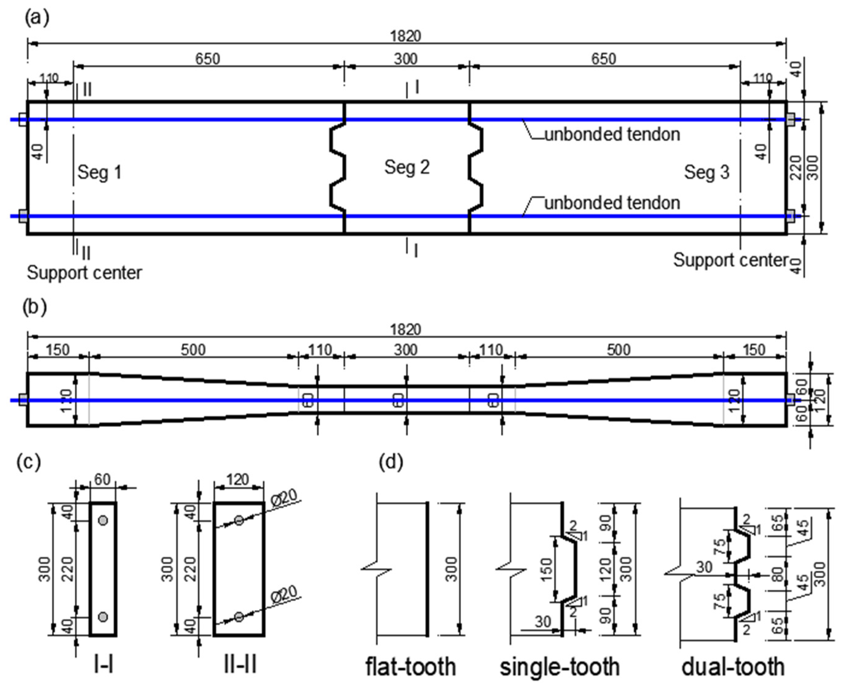
2.1. Specimen Design

Three segmental beams and one monolithic beam with a rectangular cross-section of 0.3 m in height, 0.06 m in width, and 1.82 m in length were cast and examined in the process of flexural loading. To avoid unwanted out-of-plane bending or shear of the test beams during the pretension of prestressing strands and applying bending load, the width at both ends of the test beam was increased from 0.06 m to 0.12 m. The interlocking joints of the test beams had three types of shear keys, i.e., single-, dual- and flat-key teeth, designed as per the French UHPC design code NF P 18-710 [35]. The lengths of the key teeth (i.e., 150 mm for single-key and 75 mm for dual-key) were less than 10 times the height of the key teeth (i.e., 30 mm). Moreover, the height of the key teeth was greater than twice the average length of steel fibers in the UHPC (i.e., 13 mm). In addition, the inclination angle of the key teeth (i.e., 26.6°) was lower than 30°.
The test beams were named UB-KX, in which UB was the short form for UHPC test beam, K was short for key teeth, and X represented the number of key teeth. For instance, UB-KN meant the monolithic beam had no key teeth, and UB-K1 represents a single-tooth segmental beam with one key tooth. Figure 1 exhibits the specimens’ geometries.
For each beam, two unbonded straight prestressing strands were arranged at the top and bottom. The longitudinal pre-compression stresses of the concrete were designed to be 9.5 MPa and 19 MPa, corresponding to 0.1 and 0.2 times the UHPC’s mean compressive strength, respectively. The recorded average pre-compression stresses of each beam are shown in Table 1.

2.2. Raw Materials

2.2.1. UHPC

In this research, UHPC with a goal compressive strength of 150 MPa and a goal flexural strength of 12 MPa was chosen according to the specifications [36,37]; Table 2 reveals the compound’s components. In the mix proportions, silica fume and type I Portland cement were utilized as the binding agents; silica flour was used with a 0.1 μm diameter on average; and a SiO2 mass content of over 98% was used as the filler; the fine aggregate was quartz sand, with a grain size of less than 0.6 mm. 847 kg of Portland cement per cubic meter of UHPC was required. Straight steel fibers with an average length (Lf) of 12 mm, a diameter (df) of 0.16 mm, and accordingly, an aspect ratio (Lf/df) of 75, were added with a fiber volume ratio of 2% to enhance the tensile ductility of the UHPC. The steel fibers were characterized by a density of 7.8 kg/m3, a tensile strength of 2500 MPa, and an elastic modulus of 200,000 MPa. Meanwhile, a high-performance water-reducing polycarboxylic acid agent (i.e., superplasticizer) was added to ensure good fluidity of the UHPC. The production of UHPC followed a well-established procedure suggested by Yoo et al. [8,38].
The segmental UHPC beam was divided into three segments, including the middle section with convex teeth outward, the left and right sides with concave teeth, the left- and right-side concave teeth segments cast first, and then the middle convex teeth segments cast by matching casting. The three UHPC beams were cast in three batches. For each batch, except the beam segments, six cubes with a side length of 100 mm and three prisms (100 mm × 100 mm × 400 mm) were cast for the determination of material mechanical properties. After 72 h of concrete casting, the beam segments and cubes were cured in forms at 70 °C. After pouring, the concrete was cured at room temperature. First, water-retaining film was used to cover the concrete. After 3 days, the film was removed and the color strip cloth was used to cover the concrete.
Conforming to GB/T 31387-2015 [39], the elastic modulus, compressive strength, and splitting tensile strength were verified 60 days after casting. Table 3 summarizes the test results, and shows that the compressive strength, splitting tensile strength, and modulus of elasticity were 142.6 MPa, 12.9 MPa, and 4.25 × 10⁴ MPa, respectively.

2.2.2. Steel Strand

Grade 270 low-relaxation seven-wire steel strands confirming ASTM A416 [40] were used as prestressing reinforcements in the present study. The strands had a minimum tensile strength of 1860 MPa, a nominal diameter of 15.2 mm, a nominal cross-sectional area of 140.0 mm2, and a unit weight of 1.1 kg per meter, as per ASTM A416 [40]. As reported by the supplier, the strands had a tensile yield load of 222 kN, a tensile breaking load of 261 kN, a modulus of elasticity ranging from 1.85 × 10⁵ MPa to 2.05 × 10⁵ MPa, a minimum elongation of 3.5%, and a maximum relaxation of 2.5%. Table 4 shows the material properties of the steel strands.

2.2.3. Joint Glue

A two-component modified epoxy resin with high viscosity and strength (Model: JN-P; Branch: Goodbond Co., Ltd., Changsha 410205, China) was utilized as the joint glue. Such an epoxy resin is suitable for the assembly of precast concrete segments, and has been applied in many field applications. Li et al. [41] conducted a series of shear tests on precast segmental external prestressed concrete beams, and obtained valuable test data. The results showed that the tensile strength of epoxy resin structural glue was higher than the tensile strength of concrete. Cracks appeared on the upper edge of the concrete near the glue joints when the structure was stressed. The shear bearing capacity of segmental beams was improved by configuring internal prestressed tendons. Table 5 shows the mechanical characteristics of the epoxy resin.

2.3. Test Setup and Instrumentation

The specimen was loaded in two points, and the loading device was shown in Figure 2. A hydraulic jack was used for graded symmetrical loading, the horizontal separation from the loading location to the center line of the support was 0.533 m, the shear span ratio at both ends was 2.05, and the extent of the pure bending section was 0.533 m. The vertical load was evenly divided into two loading points by the distribution beam with large stiffness. The plane dimensions of the bearing and the loading steel plates were both 200 (transverse) × 80 mm (longitudinal). The rubber plate of the same size was underlaid with the steel plate for evenly applied stress, and to prevent the local crushing of concrete. With mechanical strain gauges, a wide range of strains can be measured, even after concrete cracking or local crushing. During the loading process, the following tests were performed:
(1)
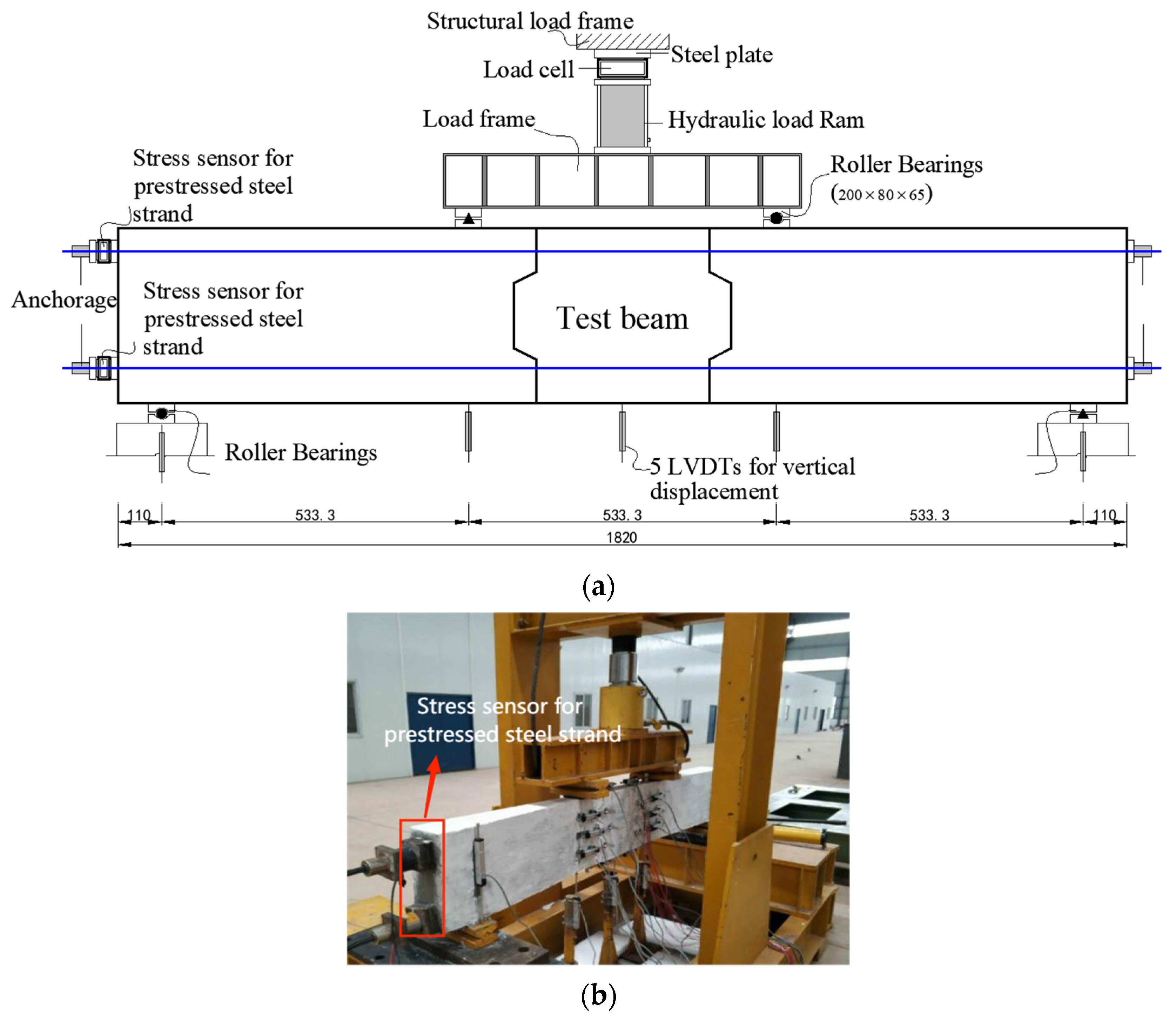
Load and deflection test. Linear variable differential transformers (LVDTs) were arranged at the mid-span, loading point, and support, in order to record the displacement changes of each point during the loading process. A 50 t pressure sensor was arranged above the hydraulic jack. It was used to measure the applied load value and finally obtain the load–deflection curve. The device layout is shown in Figure 2.
(2)
Stress increment test of steel strand. A 30 t pressure sensor was arranged on each steel bundle to test its stress increment. Table 6 shows the stress increments of steel strand in different beams. The stress increment of steel strand is an important basis for determining the ultimate stress of steel strand. At the ultimate stage, the stresses of all tendons in the tension zone were greater than 1500 MPa, but no rupture of tendons was observed.
(3)
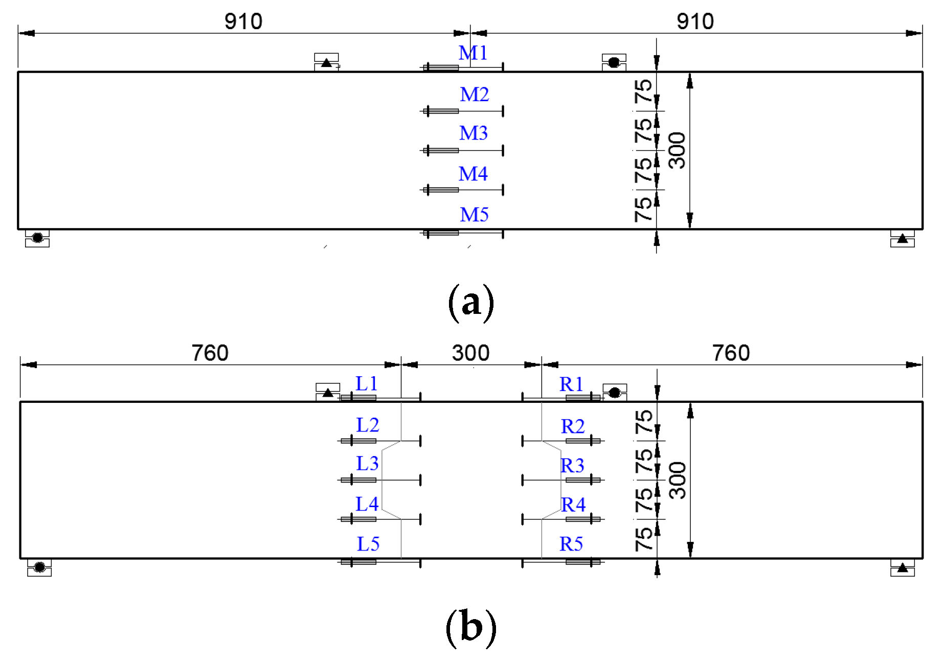
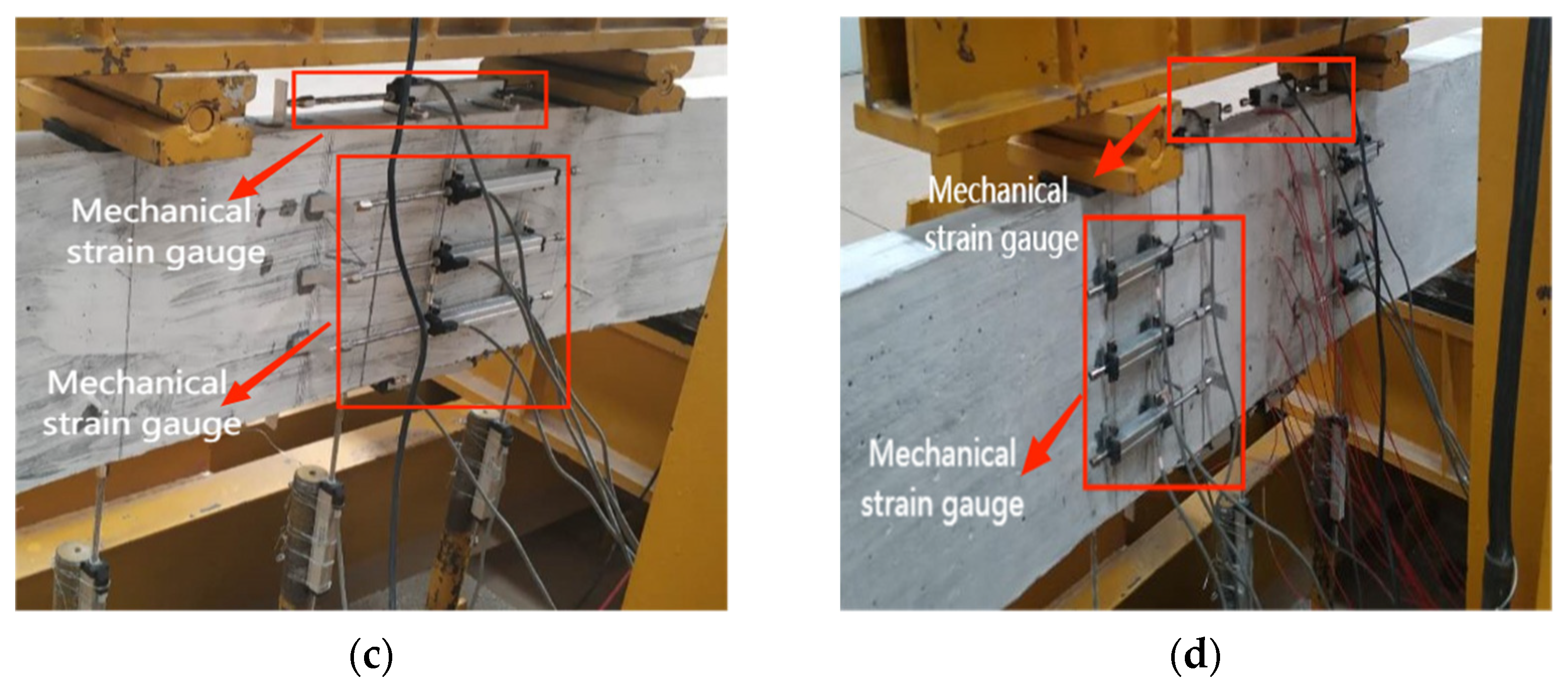
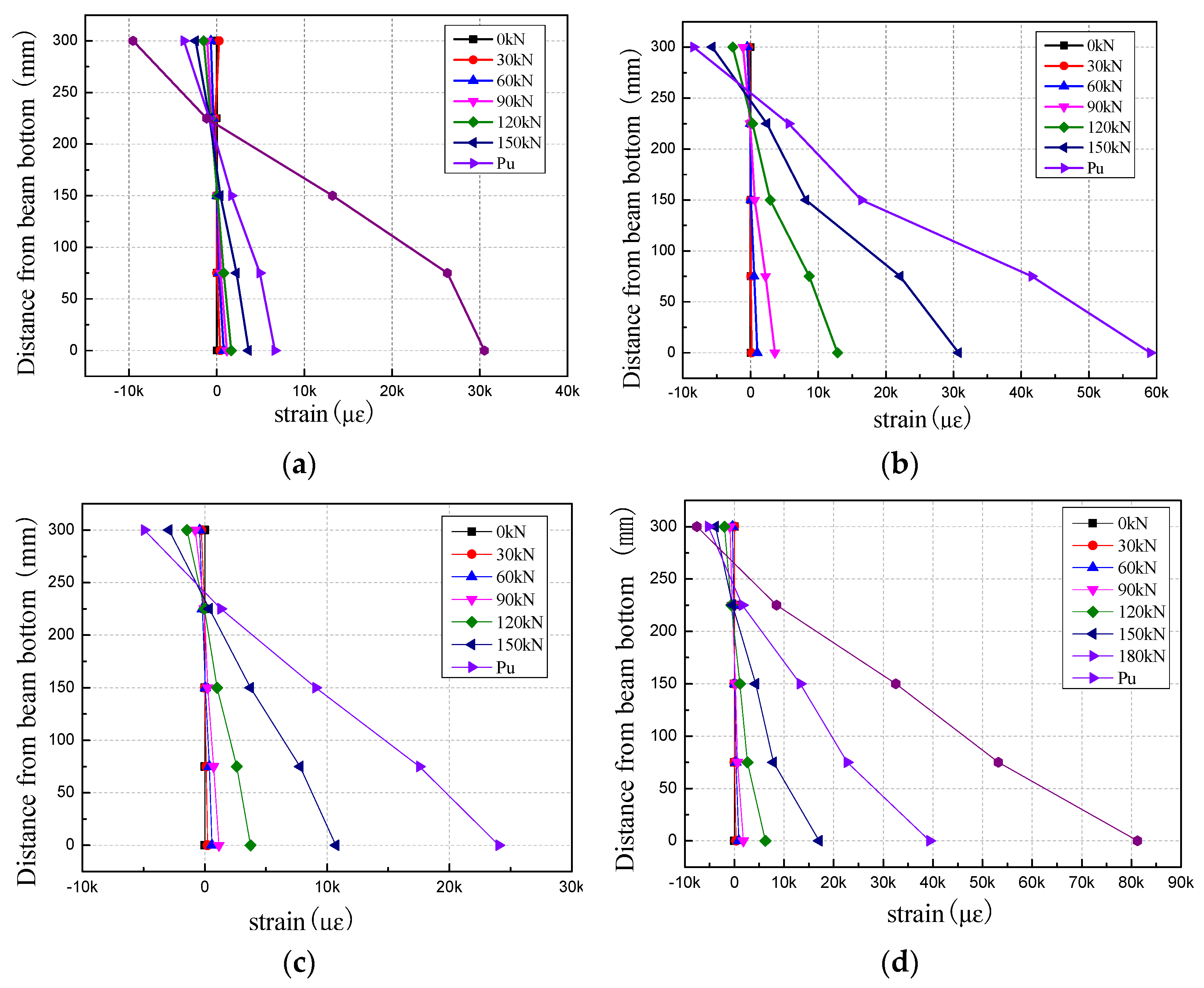
Strain test of pure bending concrete. The strain of concrete was measured by LVDTs, and 5 horizontal LVDTs were uniformly arranged along the section height. Two joint sections were tested by splicing beam, and the mid-span section was tested by casting beam. The arrangement of the measuring points is shown in Figure 3. The mechanical strain gauge placed on the monolithic beam is M1–M5 from top to bottom. The left side of the mechanical strain gauge placed on the segmental beam is L1–L5. The left side of the mechanical strain gauge placed on the segmental beam is R1–R5.
(4)
Crack observation. The crack formation law was noted when the load was applied, and the typical crack width was measured using the crack width meter.
Before the formal loading, the test beam was preloaded to check whether the instrument functioned normally. When the formal loading was carried out, 5 kN was taken as the first-stage loading until bending cracks and oblique cracks appeared. After determining the cracking load, 10 kN was taken as the first-stage loading, and the loading was controlled according to the displacement when approaching failure. After each stage was loaded, the load was held for 3 min to observe the deformation and cracks of the test beam. During the loading process, the vertical load, horizontal load, and vertical displacement were recorded automatically and synchronously according to the frequency of collecting the data in 5 s, and the crack morphology of the specimen was recorded in a timely manner. To prevent the unbonded prestressed tendons from breaking suddenly, the vertical loading was terminated when the measured strand stress reached approximately 1767 MPa (95% of the tensile strength).

3. Results and Discussion

The structural reactions during the static loading phase were measured. The cracking loads, ultimate loads, stress increment of the unbonded tendons, maximum compressive strain of the UHPC, and the ultimate deflections at mid-span are laid out in Table 6. The maximum compressive strains were adopted from the load cell in Figure 2. The stress increment in Table 6 refers to the stress increment of the steel strand. The stress increments of the strands were measured directly by the stress sensor, which arranged the anchorage position of the strand.
From the experimental results, it was observed that the monolithic beam of UB-KN had a maximum flexural strength of 119.93 kN·m. The flexural moments of the UB-K1 and UB-K2 segmental beams, both with shear keys conforming to French standard NF P 18-710 [35], were 5.16% and 9.47%, respectively, which were lower in comparison to the UB-KN monolithic beam. Due to a high concentration of rotation and deflection at individual joints, the flexural strength of the UB-K0 segmental beam with flat-key was 9.84% less than that of the UB-K1 segmental beam with single-key.
At the ultimate stage, the stresses of all tendons in the tension zone were greater than 1500 MPa, but no rupture of tendons was observed.

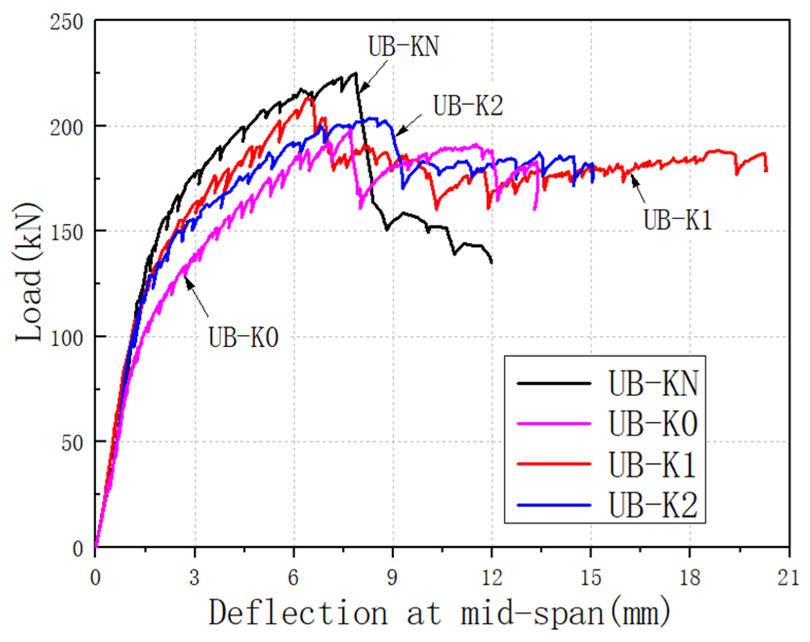
3.1. Deformation Characteristics
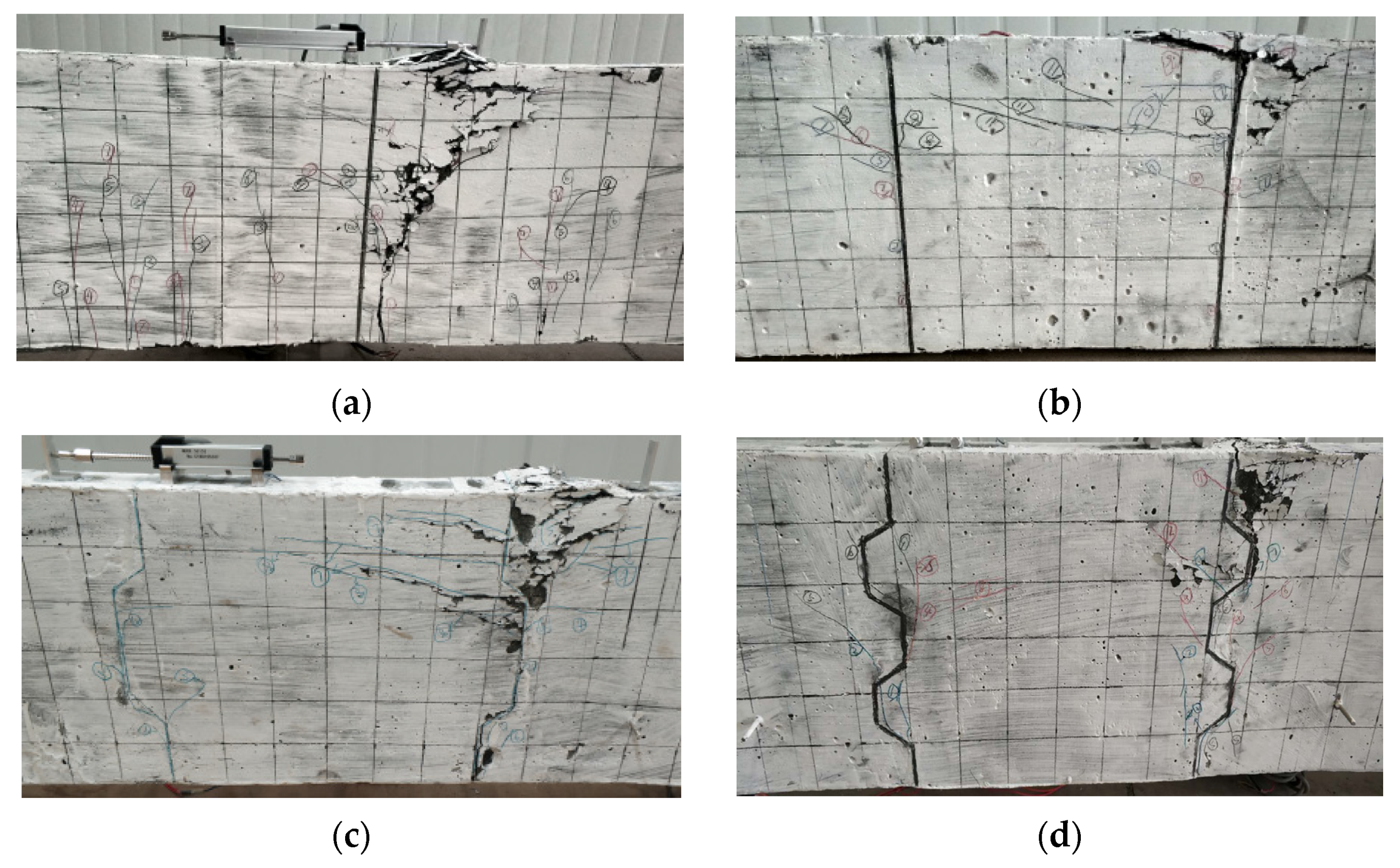
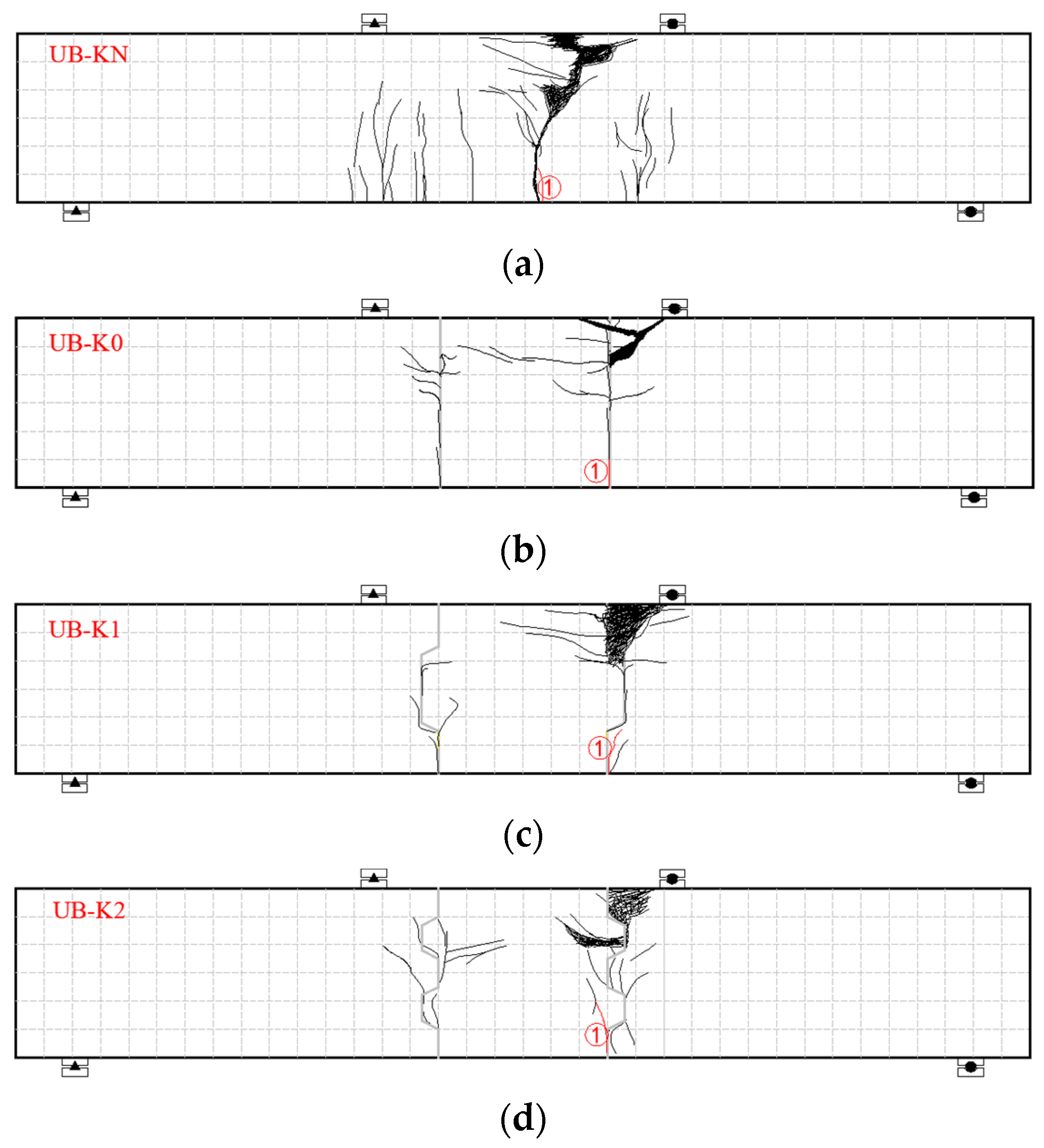
Figure 4 presents the load–deflection curves at the mid span for all beams. As the load grew, the vertical displacement of the beams increased synchronously. The relationship was initially linear, and the response became nonlinear until failure with further increases in the applied load. Consequently, the stiffnesses of all of the beams declined as the load increased because of the joint opening, the non-linear behavior of concrete in compression, the yielding of the steel, and geometrical non-linear behavior. It can be seen that the monolithic beam had a greater maximum ultimate load than those of the segmental beams. The segmental beams demonstrated similar deflection behaviors. The deflection of the UHPC beams reached an approximate maximum ultimate deflection at mid-span. The maximum deflections at the mid span of the specimens were 7.9, 8.8, 6.4, and 8.4 mm for UB-KN, UB-K0, UB-K1, and UB-K2, respectively. The number of joints had little effect on the load–deflection curve, and the ductility of the spliced beams (UB-K1) was better than that of the monolithic beam (UB-KN). The flexural strengths of the prefabricated components were 9~15% lower than those of the monolithic beams with unbonded tendons; however, beam UB-K1 showed more ductile behavior than beam UB-KN. The main reason was that the key teeth on the joint can prevent vertical cracks from developing towards the compression zone. Furthermore, the test beam could create greater deformation before the UHPC in the compression zone reached its ultimate compressive strain.

3.2. Failure Mode

Figure 5 depicts the failure pattern of each test beam under its limit state, and Figure 6 indicates the crack distribution of each test specimen. The failure mode illustrated typical flexural failure in all of the test beams. Segmental beams of UB-K0, UB-K1, and UB-K2 showed approximately similar failure behaviors. “①” in Figure 6 shows the location of the first crack, and the shaded part is the area of crushed concrete.
For the UB-K0 monolithic beam, the first vertical crack initiated at the mid-span of the beam was caused by the bending moment at the 74 kN-m applied load. As the applied load increased, the vertical crack propagated upward, and hardly any incline cracks occurred near the loading point. The vertical and inclined cracks reached the top concrete flange at 98 kN-m. The concrete was crushed, and beam specimen failed at 120 kN-m, and the corresponding deflection at mid-span was 7.9 mm. The crack patterns at failure are illustrated in Figure 5a, which is a typical flexural failure.
Ahead of the joints opening, the segmental beams performed similarly to the monolithic beam. When the cracking loads reached the value in Table 4, the critical joints opened. As the load grew, the critical joints spread broadly and extensively, and inclined cracks of 30~60 degrees appeared at the joints. Meanwhile, no distinct bending cracks were discovered between the joints. The maximum bending cracks were obviously wider than those of the monolithic beams. The two parts of the beam rotated around the critical joint. In the process of failure, the concrete of the upper flange was crushed as the vertical load reached its maximum value.

3.3. Pure Bending Section Median Strain

In order to measure the strain changes of UHPC, five horizontal LVDTs were uniformly arranged along the section height. The arrangement of the horizontal LVDTs is shown in Figure 3.
Figure 7 displays the distribution of UHPC strain at mid-span along the beam height under the load for all test beams. The average strain of the test beams altered linearly along the beam height in the process of loading, which agreed with the plane section assumption. The neutral axis kept going up as the load increased. Likewise, the same findings were obtained for monolithic beams and the segmental beams.

4. Finite Element Analysis

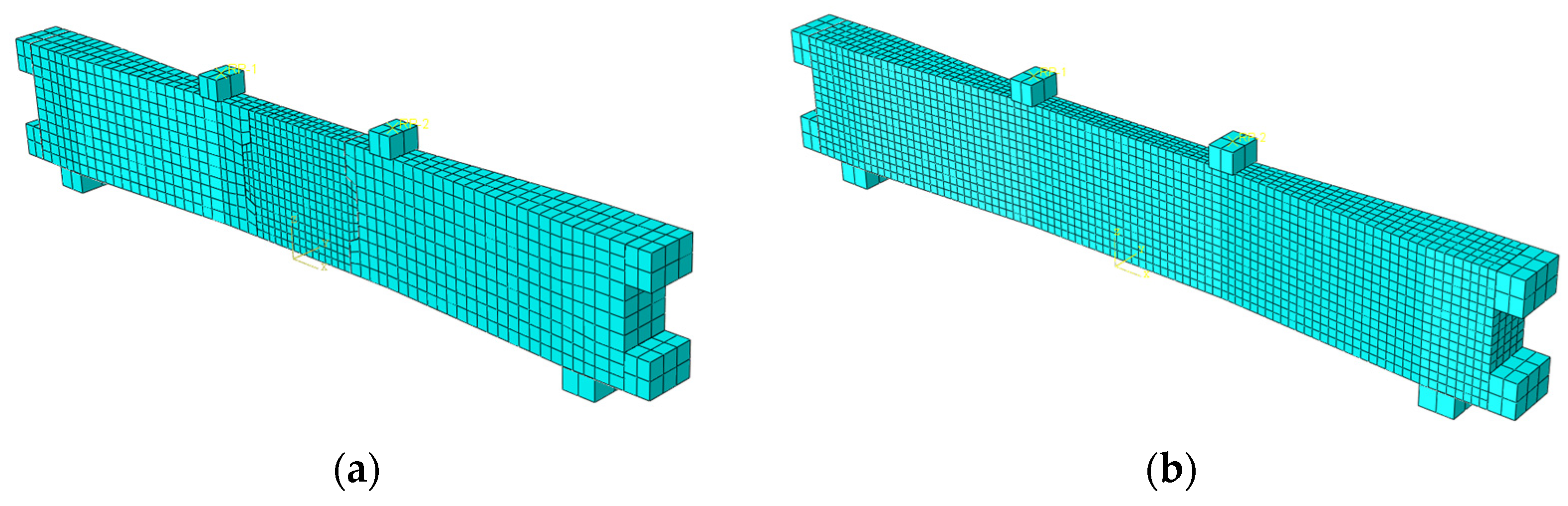
4.1. Finite Element Modeling

The commercial finite element software ABAQUS was utilized to model the flexural behavior of PCSBs with unbonded tendons and epoxy resin joints subjected to bending. This section describes various aspects of the finite element modeling approach, including material constitutive models, finite element mesh, contact and boundary conditions, unbonded tendons and loading, etc. The influence of the number of key teeth on the flexural behavior of PCSBs with unbonded tendons epoxy resin joints was analyzed.

4.2. Constitutive Material Models

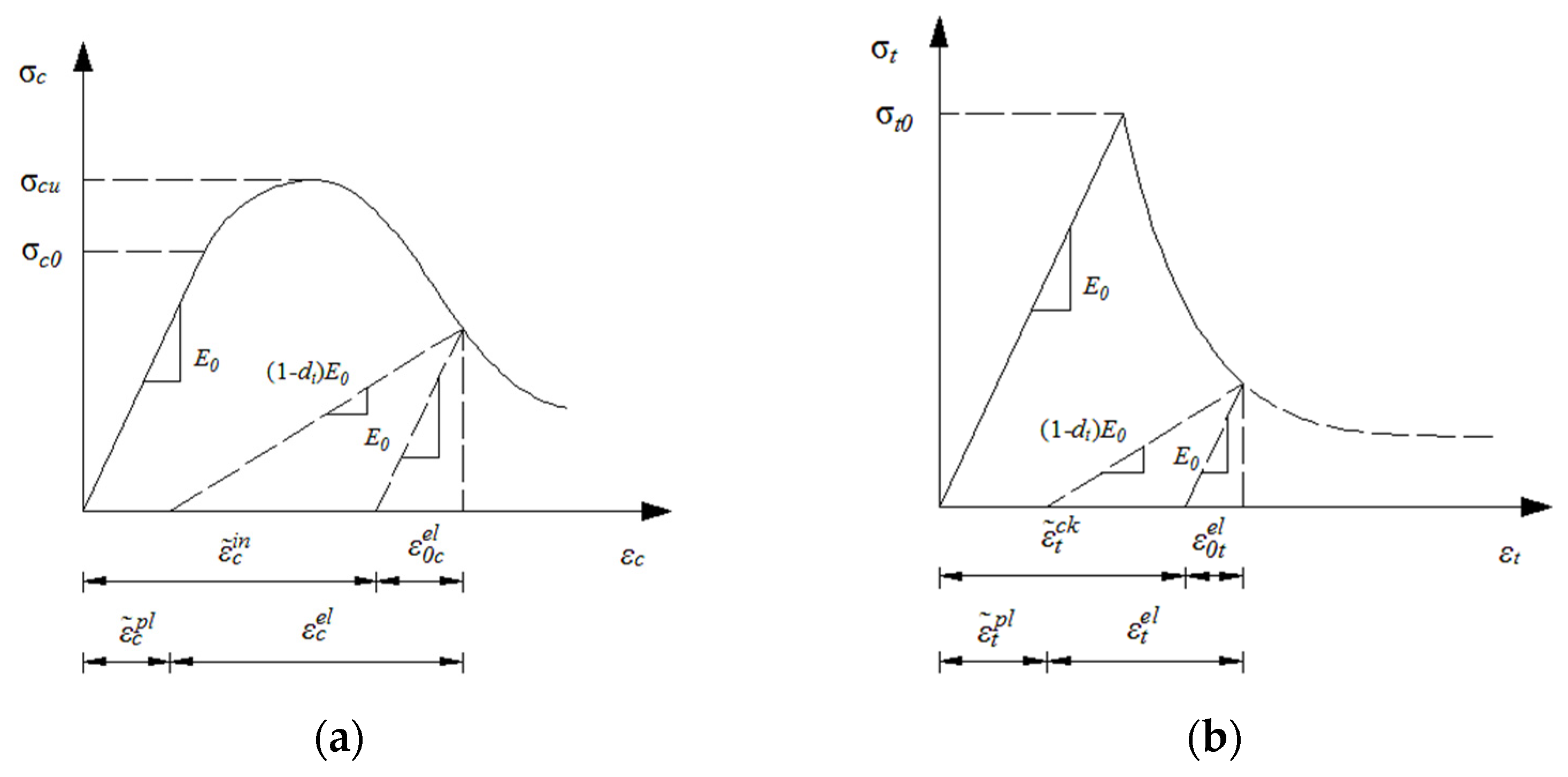
4.2.1. Concrete Model
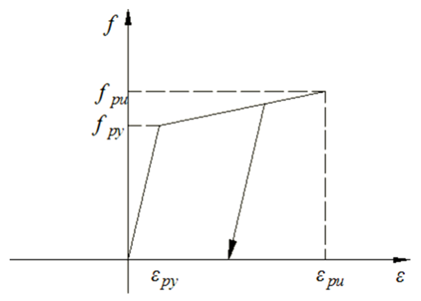
The Concrete Damaged Plasticity (CDP) model proposed by Lubliner et al. [42] and by Lee et al. [43] was cited to simulate the inelastic performance of the concrete material under loading. According to study [44], the constitutive relationship (compression and tension) of concrete is defined, and then the CDP constitutive model is determined. The damage to concrete after it enters plasticity is controlled by the equivalent plastic strain in tension ε ˜ t p l and the equivalent plastic strain in compression ε ˜ c p l , in order to control the tension and compression damage of the concrete after inelastic deformation. The CDP model stress–strain curve is illustrated in Figure 8.
Figure 8a shows the uniaxial compression stress–strain curve of concrete; d c is the compressive damage factor. When the compressive stress does not reach the initial yield stress σ c 0 , it is the linear elastic stage, and its elastic modulus is E o ; the material will not produce initial damage during this process. When the compressive stress exceeds the elastic limit and enters the hardening stage, there will be a strengthening process. When the breaking stress is reached, this is regarded as strain softening. After hardening, the material will gradually be damaged.
Figure 8b shows the uniaxial tensile stress–strain curve of concrete; d t is the tensile damage factor. When the tensile stress meets the tensile stress σ t 0 before failure, it is considered linear elastic; the elastic modulus is E o . When the material reaches the tensile failure stress, tiny cracks will be generated, which will then soften due to clusters of micro cracks. After the concrete tensile strain exceeds the tensile elastic limit strain σ t 0 , the material softens in macro-mechanics.

4.2.2. Steel Model

As shown in Figure 9 and Formula (1), the constitutive relationship of the unbonded tendons is simplified into a broken line for calculation. When unloading, the unbonded tendons adopt a curve relationship parallel to the initial stage of loading; that is, the elastic modulus during unloading adopts the initial elastic modulus.
f p = { E p ε p                                           ( ε p ε p y ) f p y + ε p ε y ε u ε y ( f p u f p y )               ( ε p y < ε p ε p u )

4.3. Finite Element Mesh

A suitable element type needs to be chosen to achieve more realistic and reliable results. To simulate the PCSBs with unbonded tendons, the steel is simulated by a two-node linear three-dimensional truss element T3D2. The supports, loading blocks, and anchors are all simulated by discrete rigid elements that are independent of each other. The mesh density will directly affect the accuracy of the finite element calculation, and the appropriate mesh size is selected according to the actual needs. Since the simulated beam in this study is a variable cross-section beam, in order to ensure that each area of the simulated beam can be divided into structured grids, the simulated beam should be divided into variable cross-sections. In this study, the mapping grid was used to divide the beam, and it was necessary to simulate the contact relationship between the various parts of the test beam. In order to ensure the easy convergence of non-linear analysis and calculation, the mesh spacing of the main stressed components is relatively dense, and the mesh spacing of the secondary stressed components is relatively sparse. The finite element model is shown in Figure 10.

4.4. Contact and Boundary Conditions

This test model included concrete beams, steel, boundary pad, loading pads, and anchor blocks. The touching relationship between the border pad, loading pads, anchor block, and concrete beam was the Tie method; that is, it was tied to the component. To better simulate the concentrated loading in the actual test, a reference point was set above the loading pad, and then the point of reference was subsequently attached to the surface of the loading pad to ensure the convergence of the finite element calculation.
Since this model used linear unbonded tendons, there was no bonding between the steel strands and the concrete beam, and the force mechanisms were independent of each other, the contact relationship adopted the coupling method to make the unbonded tendons and the concrete beam work together.
Surface-to-surface interaction was employed to model the contact between contact and concrete. Its contact properties included two types: normal behavior and tangential behavior. The contact attribute of the normal behavior selected the hard contact type; that is, the amount of pressure that could be transmitted between the contact surfaces was not limited. When the pressure was 0 or negative, the two contact surfaces split, and the corresponding contact constraints were invalid, while the tangential behavior was simulated by the Coulomb friction model with a friction coefficient of 0.7 [45].
The selection of boundary conditions was set according to the constraints on the boundaries of the actual field model test, and the boundary conditions of simple support were adopted; that is, one end was fixed while the other end was hinged.

4.5. Unbonded Tendons and Loading

The cooling method was used to simulate the actual unbonded tendons, and the stress in ABAQUS was converted into temperature load input.
T = σ c o n / ( α E p )
α = 1 × 10 - 5
The displacement loading method was employed to beam load. Since the force loading was not obvious when the load changed, the displacement increased rapidly. In non-linear analysis and calculation, it is difficult to converge due to insensitivity to load changes and large displacements; the displacement loading can not only obtain good convergence results, but also obtain the descending section of the pile-deflection curve, which was more consistent with the examination results.

5. Verification of the FE Model

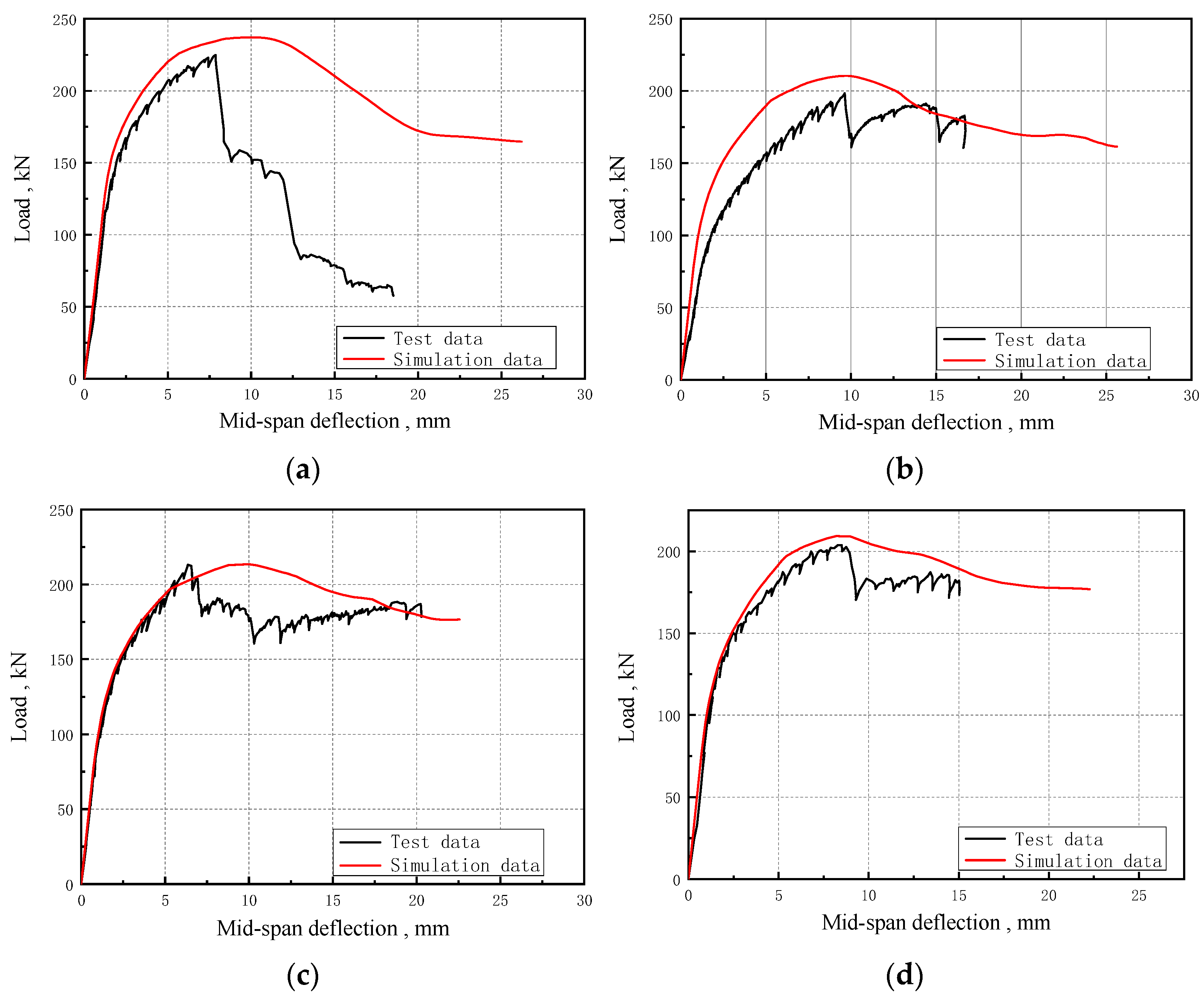
5.1. Load–Deflection Curve

Figure 11 shows that the simulated load–displacement curves were compatible with the experimental data, but the experimental data entered the plastic state earlier than the simulated data, and the UB-K0 beam behaved more obviously. This phenomenon mainly occurred for the following two reasons: firstly, as the load increased, the test beam produced stress concentration at the cracks, causing the main crack to extend upwards, while the simulated beam automatically considered all beams to participate in the work. Secondly, when the test beam reached the ultimate load, the top concrete suddenly crushed, the test beam lost its bearing capacity, thereby changing the load suddenly. However, there was no such phenomenon in the simulation, mainly because the simulated beam only considered the damage to the material. The material progressively deteriorated with increasing stress, and the load did not change suddenly.

5.2. Comparison of Simulated Data and Experimental Data

From the data analysis in Table 7, it can be found that the simulation data are higher than the test data, mainly because the computer automatically considered the force of the whole beam without stress concentration, making the ultimate load and mid-span deflection higher than that of the test beam.

6. Conclusions

This research aimed to better understand the roles of joints in the flexural behaviors of UHPC precast concrete segmental bridges. A series of tests were carried out to study the effect of joint numbers on the flexural behavior of precast concrete segmental bridges with unbonded tendons and epoxy joints. Based on the results of testing and finite element analysis, the following conclusions can be drawn.
(1)
The failure mode of the four specimens was typical flexural failure, which originated from concrete crushing of the top flange adjacent to the load point.
(2)
The flexural strengths of the prefabricated components were 9~15% lower than those of the monolithic beams with unbonded tendons.
(3)
The shape of the joints also influenced the flexural bearing capacity. The bearing capacity of the dual-tooth joint beam was 4.5% lower than that of the single-tooth one, and the bearing capacity of the flat butt joint member was 5.7% lower than that of the dual-tooth joint beam.
(4)
The commercial finite element software ABAQUS was utilized to perform finite element analysis on the precast UHPC segmental bridges with unbonded tendons, and compare this with the field model test results; the simulated load–mid-span deflection curve and ultimate bearing capacity were in good agreement with the test data.
(5)
Testing for larger-sized UHPC prefabricated fabricated beams and numerical simulation analysis of more parameters are necessary to understand the flexural load bearing capacity of unbonded prestressed concrete flexural members. In addition, it is necessary to summarize the calculation methods of UHPC prefabricated/fabricated beams with unbonded tendons and epoxy joints.

Author Contributions

H.Z. was responsible for the theoretical analysis; Y.L. was responsible for the structural analysis and technical guidance; and D.C., M.O. and X.L. were responsible for the formulation and implementation of the experimental plan. All authors have read and agreed to the published version of the manuscript.

Funding

This research was funded by the Natural Science Foundation of Hunan Province, China (No. 2022JJ50085), and the Scientific Research Project of Hunan Provincial Department of Education (Grant No. 22b0564, 20C0639), and the Open Fund of Industry Key Laboratory of Traffic Infrastructure Security Risk Management (CSUST) (16KE01).

Data Availability Statement

Not applicable.

Acknowledgments

This research was funded by the Natural Science Foundation of Hunan Province, China (No. 2022JJ50085, 2023JJ50180), and the Scientific Research Project of Hunan Provincial Department of Education (Grant No. 22b0564), and the Open Fund of Industry Key Laboratory of Traffic Infrastructure Security Risk Management (CSUST) (16KE01).

Conflicts of Interest

The authors declare no conflict of interest.

References

  1. Huang, D.; Hu, B. Concrete Segmental Bridges: Theory, Design, and Construction to AASHTO LRFD Specifications; CRC Press: Boca Raton, FL, USA, 2020. [Google Scholar]
  2. Hasan, M.; Jamil, M.; Saidi, T. Mechanical properties and durability of ultra-high-performance concrete with calcined diato-maceous earth as cement replacement. J. Mech. Behav. Mater. 2023, 32, 20220272. [Google Scholar] [CrossRef]
  3. Yuan, A.; Yang, C.; Wang, J.; Chen, L.; Lu, R. Shear behavior of epoxy resin joints in precast concrete segmental bridges. J. Bridge Eng. 2019, 24, 04019009. [Google Scholar] [CrossRef]
  4. Zhan, Y.; Li, Z.; Chen, Z.; Shao, J.; Yue, F.; Liu, F.; John, M. Experimental and numerical investigations on shear performance of key tooth joints of precast concrete segmental bridge under repeated loading. Constr. Build. Mater. 2022, 351, 128794. [Google Scholar] [CrossRef]
  5. Liu, W.; Han, B.; Yan, W. Research progress on structural mechanical properties of precast concrete segment beams. China J. Highw. Transp. 2023, 36, 81–99. [Google Scholar]
  6. Feng, Z.; Li, C.; Yoo, D.Y.; Pan, R.; He, J.; Ke, L. Flexural and cracking behaviors of reinforced UHPC beams with various reinforcement ratios and fiber contents. Eng. Struct. 2021, 248, 113266. [Google Scholar] [CrossRef]
  7. Yoo, D.Y.; Kang, S.T.; Yoon, Y.S. Enhancing the flexural performance of ultra-high-performance concrete using long steel fibers. Compos. Struct. 2016, 147, 220–230. [Google Scholar] [CrossRef]
  8. Yoo, D.Y.; Kim, S.W.; Park, J.J. Comparative flexural behavior of ultra-high-performance concrete reinforced with hybrid straight steel fibers. Constr. Build. Mater. 2017, 132, 219–229. [Google Scholar] [CrossRef]
  9. Jia, L.; Fang, Z.; Huang, Z.; Pilakoutas, K.; Wang, Q.; Tan, X. Flexural Behavior of UHPC Beams Prestressed with External CFRP Tendons. Appl. Sci. 2021, 11, 9189. [Google Scholar] [CrossRef]
  10. Khan, M.I.; Fares, G.; Abbas, Y.M.; Alqahtani, F.K. Behavior of Non-Shear-Strengthened UHPC Beams under Flexural Loading: Influence of Reinforcement Percentage. Appl. Sci. 2021, 11, 11346. [Google Scholar] [CrossRef]
  11. Yao, Y.; Mobasher, B.; Wang, J.; Xu, Q. Analytical approach for the design of flexural elements made of reinforced ultra-high performance concrete. Struct. Concr. 2021, 22, 298–317. [Google Scholar] [CrossRef]
  12. El-Helou, R.G.; Graybeal, B.A. Flexural Behavior and Design of Ultrahigh-Performance Concrete Beams. J. Struct. Eng. 2022, 148, 04022013. [Google Scholar] [CrossRef]
  13. Qiu, M.; Shao, X.; Wille, K.; Yan, B.; Wu, J. Experimental investigation on flexural behavior of reinforced ultra-high perfor-mance concrete low-profile T-beams. Int. J. Concr. Struct. Mater. 2020, 14, 1–20. [Google Scholar] [CrossRef]
  14. Kim, K.C.; Yang, I.H.; Joh, C.B. Material properties and structural characteristics on flexure of steel fiber-reinforced ultra-high performance concrete. J. Korea Concr. Inst. 2016, 28, 177–185. [Google Scholar] [CrossRef] [Green Version]
  15. Sturm, A.B.; Visintin, P.; Oehlers, D.J. Blending fibers to enhance the flexural properties of UHPFRC beams. Constr. Build. Mater. 2020, 244, 118328. [Google Scholar] [CrossRef]
  16. Yin, H.; Shirai, K.; Teo, W. Finite element modeling to predict the flexural behavior of ultra-high performance concrete mem-bers. Eng. Struct. 2019, 183, 741–755. [Google Scholar] [CrossRef]
  17. Peng, F.; Xue, W. Design approach for flexural capacity of concrete T-beams with bonded prestressed and non-prestressed FRP reinforcements. Compos. Struct. 2018, 204, 333–341. [Google Scholar] [CrossRef]
  18. Zhang, R.; Hu, P.; Chen, K.; Li, X.; Yang, X. Flexural Behavior of T-Shaped UHPC Beams with Varying Longitudinal Reinforcement Ratios. Materials 2021, 14, 5706. [Google Scholar] [CrossRef]
  19. Joshi, S.S.; Thammishetti, N.; Prakash, S.S.; Jain, S. Cracking and ductility analysis of steel fiber-reinforced prestressed con-crete beams in flexure. ACI Struct. J. 2018, 115, 1575–1588. [Google Scholar] [CrossRef]
  20. Omran, G.M.; Beygi, M.H.; Dehestani, M. Numerical analysis of externally prestressed concrete beams and parametric study of factors affecting their flexural performance. Int. J. Adv. Eng. Sci. 2020, 12, 142–157. [Google Scholar] [CrossRef]
  21. Dogu, M.; Menkulasi, F. A flexural design methodology for UHPC beams post-tensioned with unbonded tendons. Eng. Struct. 2020, 207, 110193. [Google Scholar] [CrossRef]
  22. Shao, Y.; Billington, S.L. Impact of cyclic loading on longitudinally-reinforced UHPC flexural members with different fiber volumes and reinforcing ratios. Eng. Struct. 2021, 241, 112454. [Google Scholar] [CrossRef]
  23. Zhang, Y.; Zhu, P.; Shi, J. Flexural behavior of precast UHPC beam with the prestressed bolted hybrid joint. Eng. Struct. 2020, 206, 110100. [Google Scholar] [CrossRef]
  24. Chai, S.; Guo, T.; Chen, Z.; Yang, J. Flexural Behavior of Precast Concrete Segmental Box-Girders with Dry Joints. Adv. Civ. Eng. 2020, 2020, 8895180. [Google Scholar] [CrossRef]
  25. Peng, H.; Zhang, Z.; Zou, Y.; Guo, J.; Zhang, X.; Zeng, X. Bending Performance of Epoxy Adhesive Joints of Prefabricated Concrete Elements. Front. Mater. Sci. 2022, 9, 859532. [Google Scholar] [CrossRef]
  26. Fu, J.; Yuan, A.; Wan, S. Behavior of Fiber Reinforced Key Joints in Precast Concrete Segmental Bridge: Experimental and Numerical Analysis. J. Bridge Eng. 2021, 26, 04021053. [Google Scholar] [CrossRef]
  27. Peng, K.; Yan, B. Experimental study of the flexural behavior of ultra-high-performance concrete beam with the wet joint. Mag. Concr. Res. 2022, 74, 70–80. [Google Scholar] [CrossRef]
  28. Liu, T.; Wang, Z.; Guo, J.; Wang, J. Shear strength of dry joints in precast UHPC segmental bridges: Experimental and theo-retical research. J. Bridge Eng. 2019, 24, 04018100. [Google Scholar] [CrossRef]
  29. Yuen, T.Y.P.; Halder, R.; Chen, W.W.; Zhou, X.; Wen, T.H. DFEM of a post-tensioned precast concrete segmental bridge with unbonded external tendons subjected to prestress changes. Structures 2020, 28, 1322–1337. [Google Scholar] [CrossRef]
  30. Mirrashid, M.; Naderpour, H. Recent Trends in Prediction of Concrete Elements Behavior Using Soft Computing (2010–2020). Arch. Comput. Methods Eng. 2021, 28, 3307–3327. [Google Scholar] [CrossRef]
  31. Naderpour, H.; Haji, M.; Mirrashid, M. Shear capacity estimation of FRP-reinforced concrete beams using computational intelligence. Structures 2020, 28, 321–328. [Google Scholar] [CrossRef]
  32. Ahmed, G.H.; Aziz, O.Q. Shear strength of joints in precast post-tensioned segmental bridges during 1959–2019, review and analysis. Structures 2019, 20, 527–542. [Google Scholar]
  33. Le, T.D.; Pham, T.M.; Hao, H. Numerical study on the flexural performance of precast segmental concrete beams with un-bonded internal steel tendons. Constr. Build. Mater. 2020, 248, 118362. [Google Scholar] [CrossRef]
  34. Jiang, H.; Cao, Q.; Liu, A.; Wang, T.; Qiu, Y. Flexural behavior of precast concrete segmental beams with hybrid tendons and dry joints. Constr. Build. Mater. 2016, 110, 1–7. [Google Scholar]
  35. NF P 18-710; Design of Concrete Structures: Specific Rules for Ultra-High-Performance Fiber Reinforced Concrete (UHPFRC). French Association for Civil Engineering (AFNOR): Paris, France, 2016.
  36. T/CECS 10107-2020; Technical Requirements for Ultra-High Performance Concrete. China Engineering Construction Standardization Association: Beijing, China, 2020.
  37. NF P 18-470; Design of Concrete Structures: Ultra-High Performance Fiber-Reinforced Concrete. Specifications, Performance, Production and Conformity. French Association for Civil Engineering (AFNOR): Paris, France, 2016.
  38. Yoo, D.Y.; Yoon, Y.S. Structural performance of ultra-high-performance concrete beams with different steel fibers. Eng. Struct. 2015, 102, 409–423. [Google Scholar]
  39. GB/T 31387-2015; Reactive Powder Concrete[S]. Standards Press of China: Beijing, China, 2015.
  40. ASTM A416/A416M-17a; Standard Specification for Low-Relaxation; Seven-Wire Steel Strand for Prestressed Concrete. ASTM International: West Conshohocken, PA, USA, 2017.
  41. Li, G.; Yang, D.; Lei, Y. Combined shear and bending behavior of joints in precast concrete segmental beams with external tendons. J. Bridge Eng. 2013, 18, 1042–1052. [Google Scholar]
  42. Lubliner, J.; Oliver, J.; Oller, S. A plastic-damage model for concrete. Int. J. Solids Struct. 1989, 25, 299–326. [Google Scholar] [CrossRef]
  43. Lee, J.; Fenves, G.L. Plastic-damage model for cyclic loading of concrete structures. J. Eng. Mech. 1998, 124, 892–900. [Google Scholar] [CrossRef]
  44. Naeimi, N.; Moustafa, M.A. Compressive behavior and stress-strain relationships of confined and unconfined UHPC. Constr. Build. Mater. 2021, 272, 121844. [Google Scholar] [CrossRef]
  45. S.B.G. AASHTO-PCI-ASBI; Segmental Box Girder Standards for Span-by-Span and Balanced Cantilever Construction. American Association of State Highway and Transportation Officials: Washington, DC, USA; Precast/Prestressed Concrete Institute: Chicago, IL, USA; American Segmental Bridge Institute: Phoenix, AZ, USA, 1997.
Figure 1. Geometries of the test beams (units: mm): (a) elevation of specimen UB-K2; (b) top view of specimens; (c) sectional view; and (d) geometric details of key tooth.
Buildings 13 01643 g001
Figure 2. Setup of beam test: (a) schematic (units: mm); and (b) photograph.
Buildings 13 01643 g002
Figure 3. Strain gauge arrangements of (a,c) monolithic and (b,d) segmental beams (units: mm).
Buildings 13 01643 g003aBuildings 13 01643 g003b
Figure 4. Mid-span load-deflection curves of all beams.
Buildings 13 01643 g004
Figure 5. Failure patterns of (a) UB-KN; (b) UB-K0; (c) UB-K1; and (d) UB-K2.
Buildings 13 01643 g005
Figure 6. Cracks diagrams of (a) UB-KN; (b) UB-K0; (c) UB-K1; and (d) UB-K2.
Buildings 13 01643 g006
Figure 7. Cross−sectional strain distributions at pure bending regions of (a) UB-KN; (b) UB-K0; (c) UB-K1; and (d) UB-K2.
Buildings 13 01643 g007
Figure 8. Constitutive models of concrete based on damaged plasticity under (a) uniaxial compression; and (b) uniaxial tension.
Buildings 13 01643 g008
Figure 9. Constitutive relationship of steel.
Buildings 13 01643 g009
Figure 10. Finite element models of (a) segment prefabricated splicing and (b) segmental prefabricated integral beams.
Buildings 13 01643 g010
Figure 11. Comparisons of FEA and experimental load–displacement curves of (a) UB-KN; (b) UB-K0; (c) UB-K1; and (d) UB-K2.
Buildings 13 01643 g011
Table 1. Summary of parameters of testing specimens.
Name of BeamNumber of JointsType of JointEffective Stress of Tendons (MPa)Mean Compressive Stress at Mid-Span (MPa)
UpperBottom
UB-K02flat-key1049.31030.316.17
UB-K12single-key1050.91026.816.16
UB-K22dual-key1031.01018.215.94
UB-KN0monolithic beam1102.61019.516.50
Table 2. Mix proportions of UHPC material by relative weight ratios to cement.
W/B 1Relative Weight Ratios to CementSteel Fiber 2
WaterCementSilica FumeSilica FlourQuartz SandSuper Plasticizer
0.160.2241.00.250.31.110.022%
1 W/B water-to-binder ratio. 2 Volume percent of steel fiber in a 1 m3 UHPC material mix.
Table 3. Characteristics of UHPC.
Cube Compressive Strength (MPa)Split Strength
(MPa)
Modulus of Elasticity (MPa)
142.612.94.25 × 104
Table 4. Characteristics of steel strands.
Diameter
(mm)
Area
(mm2)
Ultimate Strength (MPa)Modulus of Elasticity (MPa)Elongation (%)Relaxation
(%)
15.2140.018601.95 × 1053.50.3
Table 5. Mechanical characteristics of joint glue (units: MPa).
Test Parameters12-h Compressive Strength7-Day Compressive StrengthOblique Shear StrengthPositive Tensile Bond Strength of Glue to Concrete
Test result5894304.3
Table 6. The main result of test beams.
Name of
Specimen
Cracking Loads
(kN)
Ultimate
Flexural Moment
(kN·m)
Ultimate Load
(kN)
Maximum
Deflection
at Mid-Span
(mm)
The Maximum Compressive Strain of UHPC
(10−6)
Stress Increment (MPa)
Tensile
Zone
Compressive Zone
UB-KN138.8119.93225.07.99538−58.5327.2
UB-K097.3102.55192.48.88679109.4576.4
UB-K1135.4113.74213.46.47268101.0363.2
UB-K2129.6108.57203.78.47522106.1514.7
Table 7. Comparison of main data between simulation and experiment.
NumberUltimate Load, kNMid-Span Deflection, mm
Test DataSimulation DataT/STest DataSimulation Data
UB-KN225.00237.180.957.9010.00
UB-K0192.40210.420.918.809.61
UB-K1213.40213.501.008.3010.00
UB-K2203.70209.220.978.408.20
Disclaimer/Publisher’s Note: The statements, opinions and data contained in all publications are solely those of the individual author(s) and contributor(s) and not of MDPI and/or the editor(s). MDPI and/or the editor(s) disclaim responsibility for any injury to people or property resulting from any ideas, methods, instructions or products referred to in the content.

