

Insight into the Mechanical Performance of the TRECC Repaired Cementitious Composite System after Exposure to Freezing and Thawing Cycle
Abstract
:1. Introduction

| Concrete Substrate | Test Method | Reference | Studied Parameters |
|---|---|---|---|
| ECC | Tensile test | [10,14,16] | Type and strength of cement matrix materials, the type of fibers, effect of geometric type, and weaving method of PE added |
| Bending test | [12,14,16,18] | ||
| Shear test | [16] | ||
| ECC-NC | Tensile test | [31,32,34,35] | Interfacial failure mode, interfacial bonding strength, interface roughness, effects of concrete strength grade, thickness of reinforcement layer, changes in ECC mix ratio, and temperature |
| Bending test | [19,20,21,23,25,26,27,28,29,32] | ||
| Shear test | [32,36] |
2. Materials and Methods
2.1. Materials
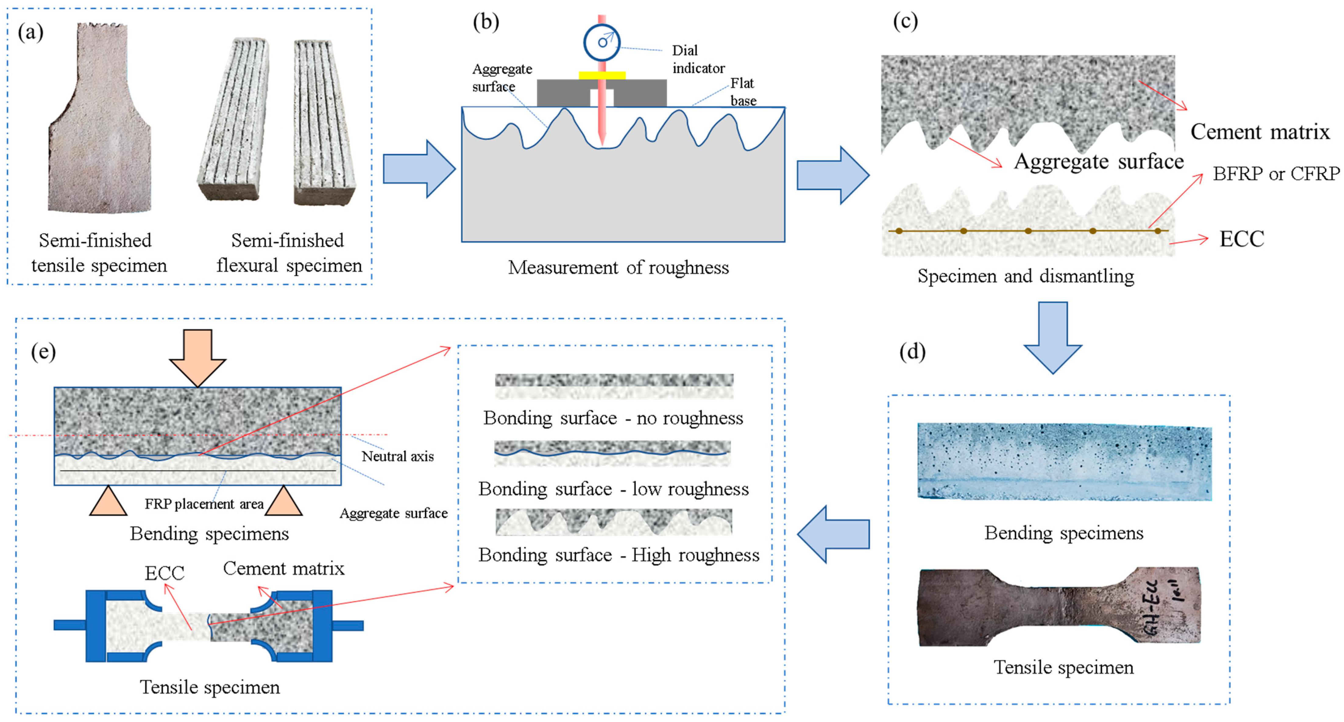
2.2. Sample Preparation
- (i)
- Mechanical properties test of TRECC under freeze–thaw cycles
- (ii)
- Mechanical properties test of TRECC1-NC under freeze–thaw cycles
3. Experimental Program and Methods
- After 24 h of casting, the sample was removed and placed in a standard curing chamber with a temperature of 20 °C ± 2 °C and humidity of ≥95% [61]. One week before the freeze–thaw test, the specimens required in the two types of tests i and ii were taken out and dehumidified at room temperature, and the specimens were placed in a rapid freeze–thaw test box. According to the “ordinary concrete long-term performance and durability test method” (GB/T50082-2009) [62], the rapid freeze–thaw method requires that each freeze–thaw cycle should be 6 h, and the melting time should not be less than 1/4 of the freezing time. During freezing and thawing, the center temperature of the specimen should be controlled at −18 °C ± 2 °C and 5 °C ± 2 °C, respectively. Therefore, the test temperature is −18 °C; the freezing time is 4 h, and the melting time is 2 h.
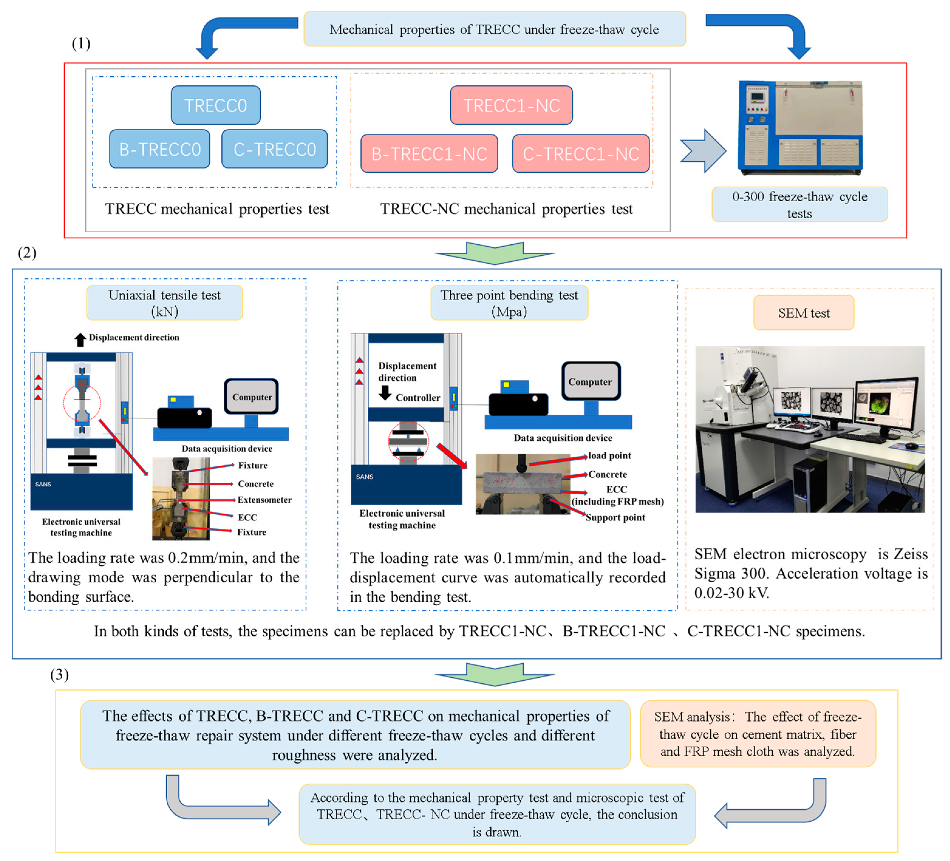
- The mechanical properties test and microstructure test were carried out. The following tests were carried out on the i and ii specimens:
- (1)
- (2)
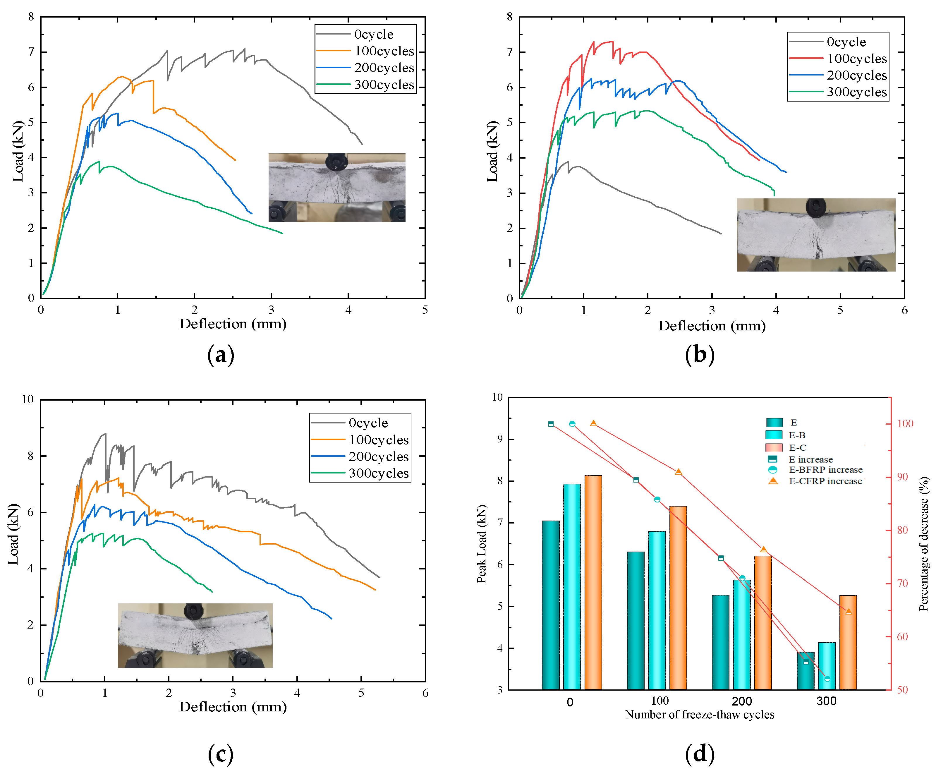
- Bending test: The three-point bending test was carried out using an electronic universal testing machine controlled by SANS (Bairoe, Shanghai, China). The loading rate was 0.1 mm/min, and the load–displacement curve was automatically recorded in the bending test.
- (3)
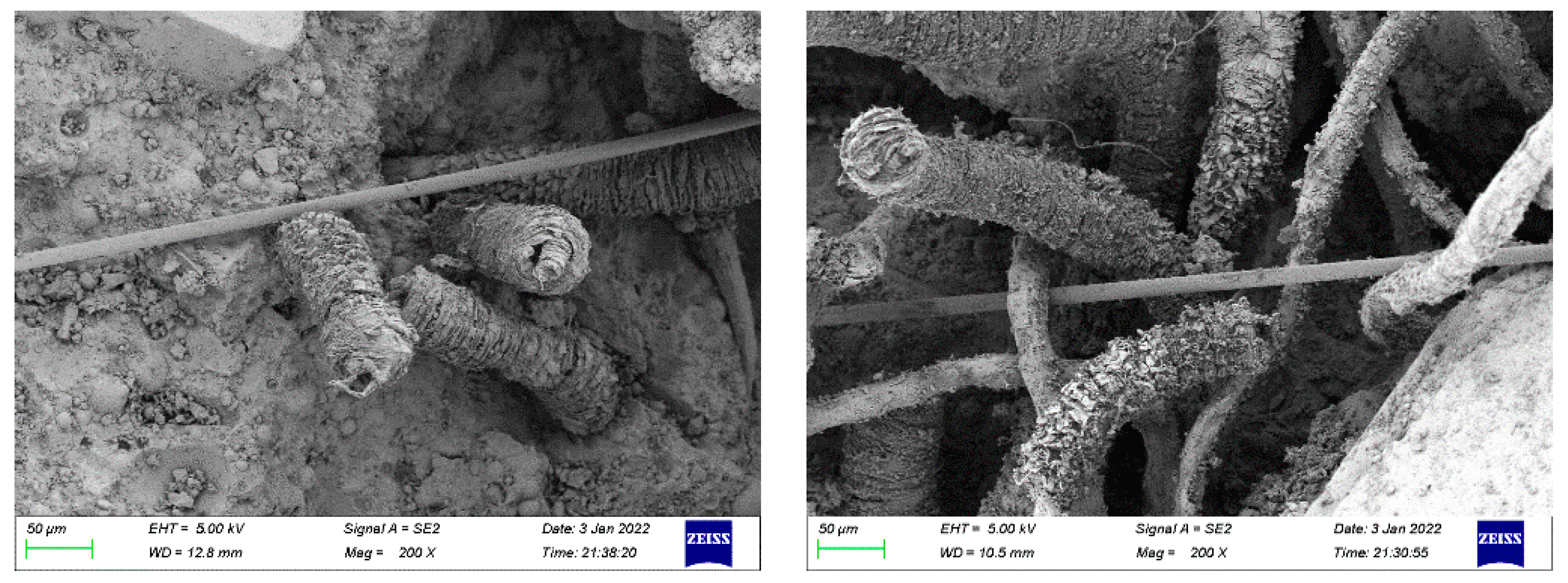
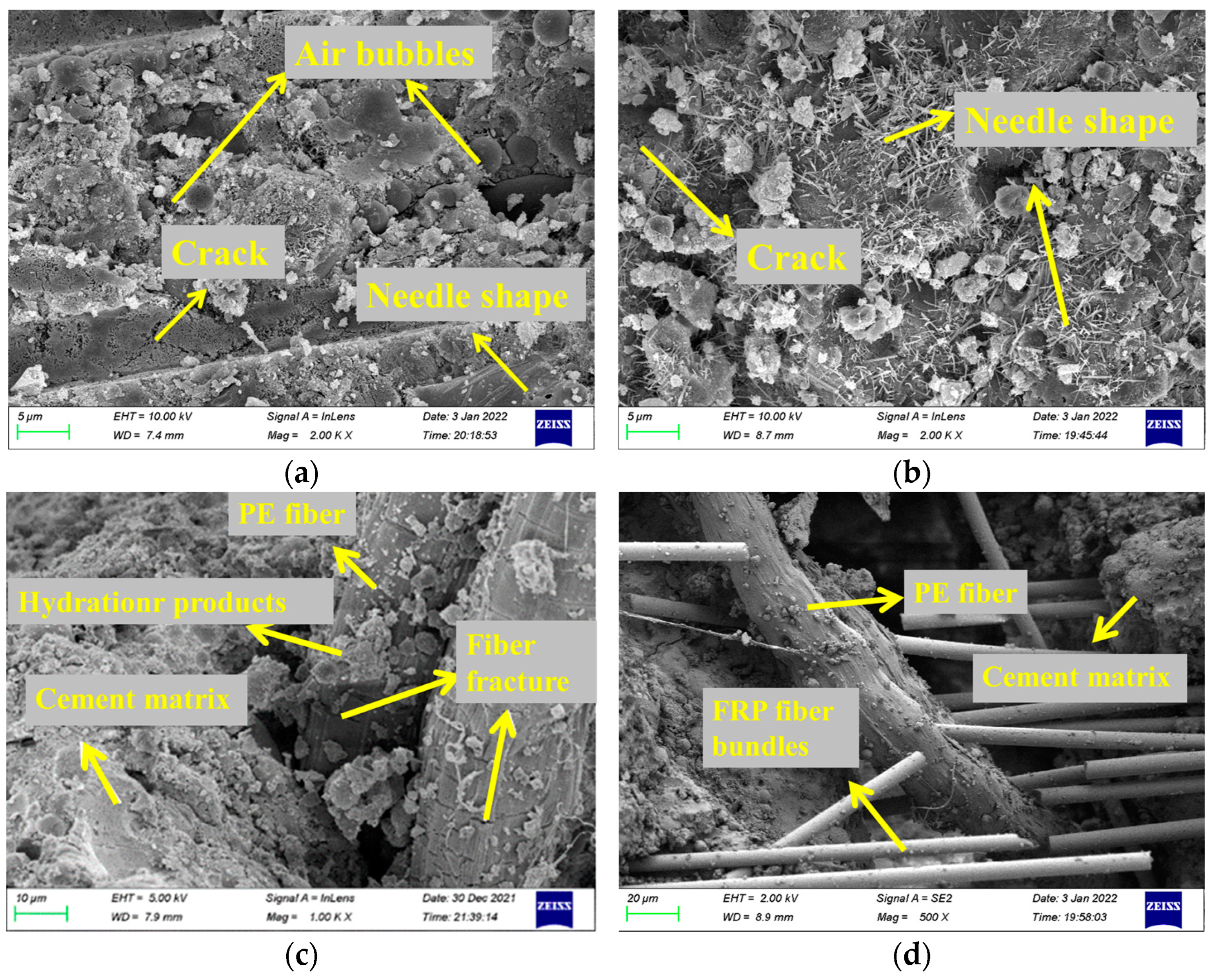
- Microstructure analysis: Zeiss Sigma 300, Oberkochen, Germany, (magnification 10–106 times) was used for the TRECC reinforcement layer after freeze–thaw cycles; acceleration voltage: 0.02–30 kV) SEM electron microscope test; the bonding interface between TRECC-NC was observed using an electron microscope.
- The mechanical properties and microscopic phenomena of the TRECC and TRECC-NC repair system under different roughness under 0–300 freeze–thaw cycles were analyzed.
4. Results and Discussion
4.1. Mechanical Properties of TRECC Matrix Material under Freeze–Thaw Cycles
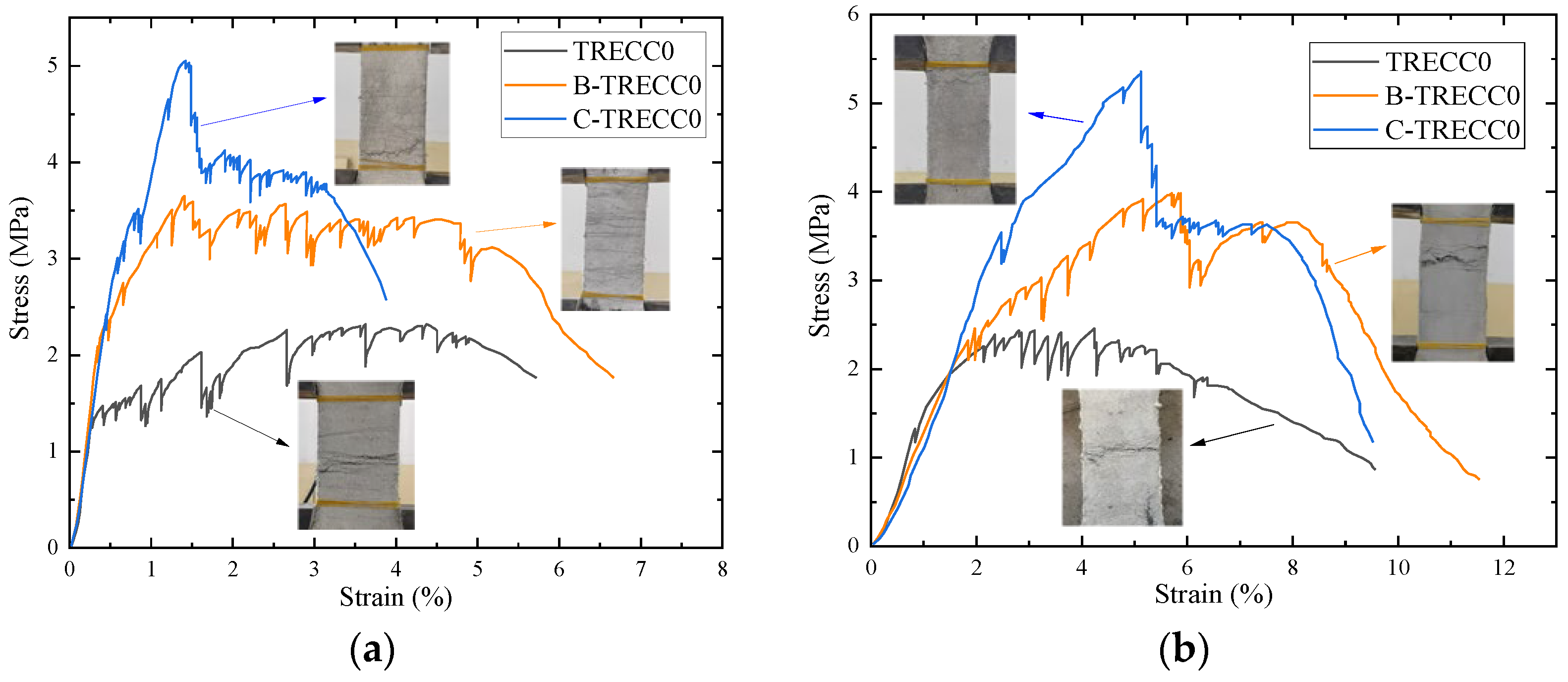
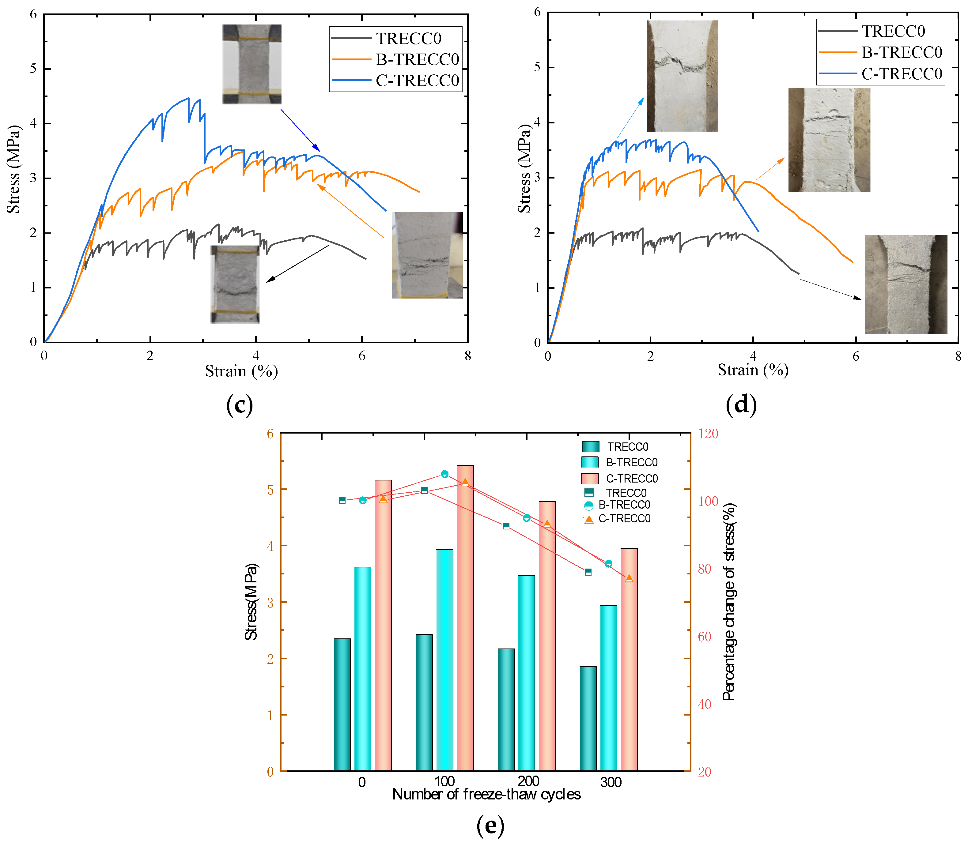
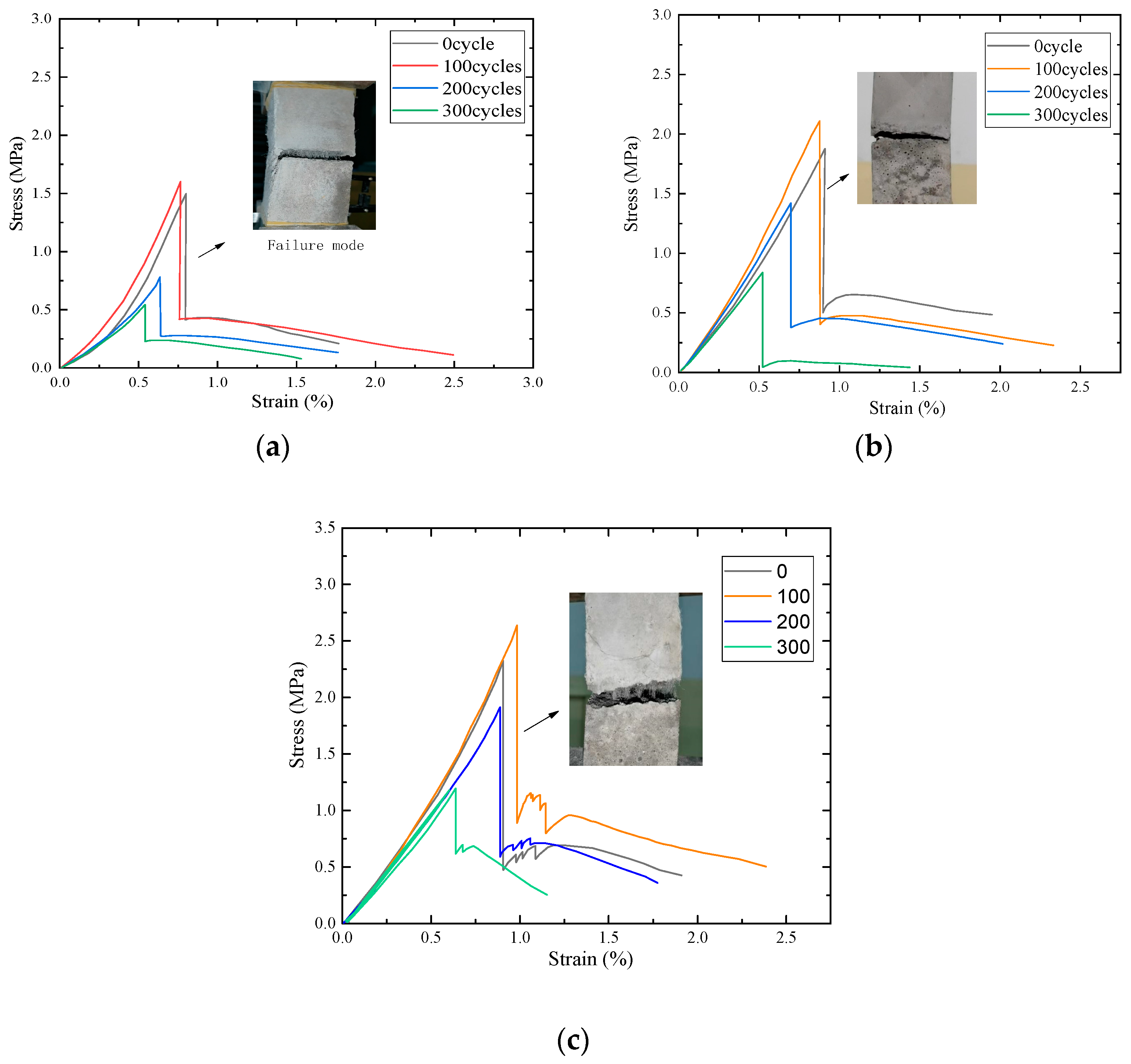
4.1.1. Tensile Test
4.1.2. Bending Test
4.2. Performance Test of TRECC-NC Repair System
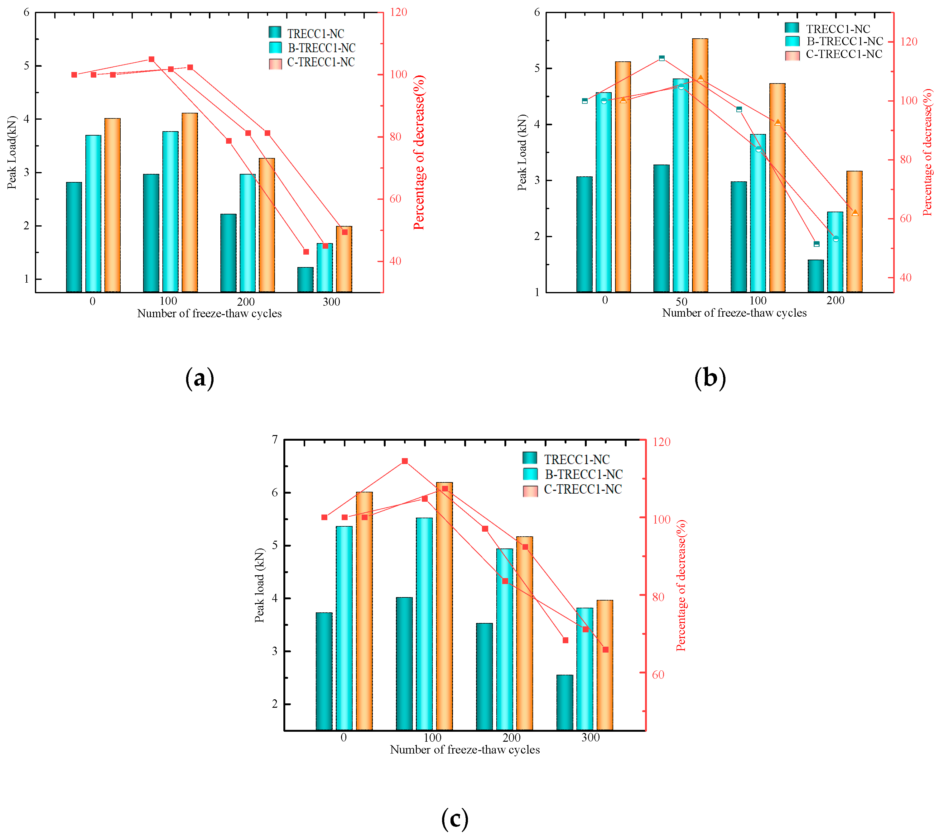
4.2.1. Bending Test Results
4.2.2. TRECC0-NC Research on Interface Properties
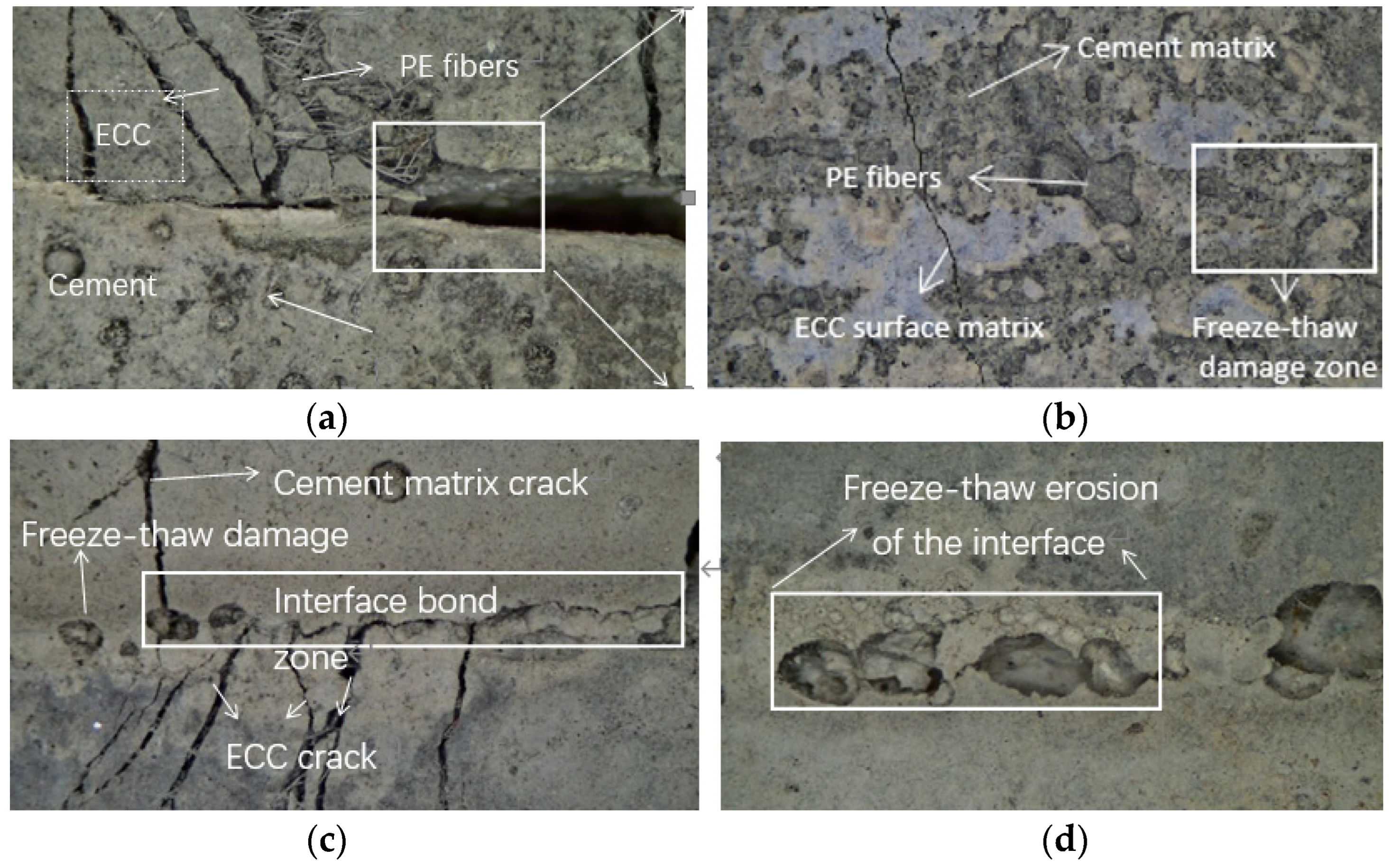
4.3. Microstructural Analysis
Microscopic Observation
5. Conclusions
- In the tensile test of TRECC, B-TRECC, and C-TRECC, with the increase of the number of freeze–thaw cycles, the strength of the three types of specimens increases continuously. C-TRECC0 exhibits the best performance with an increase 55.3% for 100 freeze–thaw cycles and 50.8% for 200 freeze–thaw cycles compared to TRECC. However, after 300 freeze–thaw cycles, the ultimate strength of the specimen is reduced by 23.4%, compared to 0 freeze–thaw cycles.
- For TRECC1-NC, B-TRECC1-NC, and C-TRECC1-NC specimens, adding FRP grid cloth or increasing interface roughness can effectively improve the strength of the specimens, whether at room temperature or under the action of freeze–thaw cycles. Due to the existence of roughness, the bite force and friction force between the bonding interface are increased from 0 to 300 freeze–thaw cycles. The mechanical properties with the highest roughness show the best mechanical performance. The reinforcement effect of FRP is as follows: BFRP > CFRP > ECC.
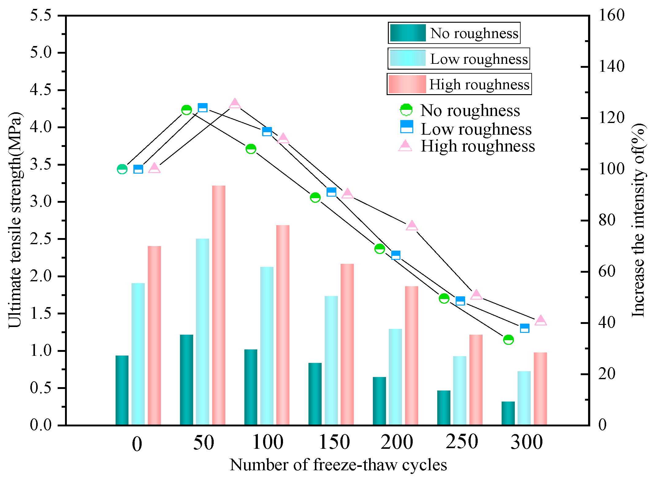
- With the increase of freeze–thaw cycles, the mechanical performance of the TRECC0-NC repair system can be affected. The ultimate failure strength of the specimens with three degrees of roughness increases initially and then decreases with the accumulation of freeze–thaw cycles. Moreover, the bonding performance of the reinforcement system with the highest roughness shows the best.
- The ECC-NC repair system was found to be susceptible to freeze–thaw damage, and the amount of surface spalling also showed a significant correlation with its flexural strength. ECC exhibits good cracking control ability, which increases with the interfacial roughness and shows good frost resistance and secondary strengthening effect under freeze–thaw cycles. However, as the freeze–thaw cycle process continues, their cooperative working ability is weakened. Nevertheless, due to the dense compactness of ECC, the internal fiber of ECC and the concrete matrix exhibits good adhesion even after undergoing freeze–thaw cycles. It is found that the specimen can exhibit good strain-hardening characteristics when it begins to fracture.
- This study can effectively solve the problems of time-consuming, cumbersome steps and expensive prices of traditional concrete reinforcement methods. Results indicate that using B-TRECC or C-TRECC can maximize the mechanical properties of FRP and limit the cracking process of concrete to a certain extent, which can be utilized to reinforce the cracking components or damaged engineering structures in cold regions.
Author Contributions
Funding
Data Availability Statement
Conflicts of Interest
References
- Zheng, X.Y.; Wang, Y.; Zhang, S.Q.; Xu, F.; Zhu, X.; Jiang, X.; Zhou, L.; Shen, Y.; Chen, Q.; Yan, Z.; et al. Research progress of the thermophysical and mechanical properties of concrete subjected to freeze-thaw cycles. Constr. Build. Mater. 2022, 330, 127254. [Google Scholar] [CrossRef]
- Jia, H.Y. Theoretical Model and Experimental Study on Freeze-Thaw Damage Mechanism of Porous Rock and Fractured Rock Mass. Ph.D. Thesis, China University of Geosciences, Xi’an, China, 2016. [Google Scholar]
- Chen, J.X. Research on Prevention and Control Technology of Tunnel Frost Damage. Master’s Thesis, Chang’an University, Xi’an, China, 2007. [Google Scholar]
- Feng, Q.; Wang, G.; Jiang, B.S. An analytical method for the analysis of tunnel surrounding rock melting in seasonal cold regions. J. Geotech. Eng. 2015, 37, 1835–1843. [Google Scholar]
- Luo, Y.B. Study on Frost Damage Classification and Prevention Technology of Tunnel in Cold Region. Ph.D. Thesis, Beijing Jiaotong University, Beijing, China, 2010. [Google Scholar]
- Lai, Y.M.; Wu, Z.W.; Zhu, Y.L.; Ling, F.; Zhu, L.N. Viscoelastic analytical solution of frost heaving force of tunnel in cold region. J. Railw. 1999, 6, 70–74. [Google Scholar]
- Wang, H.; Chen, W.Z. Sensitivity analysis of mechanical parameters of surrounding rock of Galongla tunnel to deformation. J. Geotech. Eng. 2012, 34, 1548–1553. [Google Scholar]
- Lai, J.; Wang, X.; Qiu, J.; Zhang, G.; Chen, J.; Xie, Y.; Luo, Y. A state-of-the-art review of sustainable energy based freeze proof technology for cold-region tunnels in China. Renew. Sustain. Energy Rev. 2018, 82, 3554–3569. [Google Scholar] [CrossRef]
- Li, M.; Li, V.C. High-early-strength ECC for rapid durable repair, material properties. ACI Mater. 2011, 108, 3–12. [Google Scholar]
- Zhang, Z.; Qin, F.; Ma, H.; Xu, L. Tailoring an impact resistant engineered cementitious composite (ECC) by incorporation of crumb rubber. Construct. Build. Mater. 2020, 262, 120116. [Google Scholar] [CrossRef]
- Li, M.; Li, V.C. Cracking and healing of engineered cementitious composites under chloride environment. ACI Mater. 2011, 108, 333–340. [Google Scholar]
- Zhang, Z.G.; Hu, J.; Ma, H. Feasibility study of ECC with self-healing capacity applied on long-span steel bridge deck overlay. Int. J. Pavement Eng. 2019, 20, 884–893. [Google Scholar] [CrossRef]
- Zhou, J.; Pan, J.; Leung, C.K. Mechanical behavior of fiber-reinforced engineered cementitious composites in uniaxial compression. Mater. Civ. Eng. 2015, 27, 04014111. [Google Scholar] [CrossRef]
- Lin, Z. Research on Impact Resistance of ECC Crash Barrier Material. Master’s Thesis, Southeast University, Nanjing, China, 2017. [Google Scholar]
- Li, V.C.; Wu, C.; Wang, S.; Ogawa, A.; Saito, T. Interface tailoring for strain-hardening polyvinyl alcohol-engineered cementitious composite(PVA-ECC). ACI Mater. 2002, 99, 463–472. [Google Scholar]
- Zhou, S.; Xie, L.; Jia, Y.; Wang, C. Review of Cementitious Composites Containing Polyethylene Fibers as Repairing Materials. Polymers 2020, 12, 2624. [Google Scholar] [CrossRef] [PubMed]
- Zhang, Z.; Zhang, Q.; Li, V.C. Multiple-scale investigations on self-healing induced mechanical property recovery of ECC. Cem. Concr. Compos. 2019, 103, 293–302. [Google Scholar] [CrossRef]
- Colombo, I.G.; Colombo, M.; Prisco, M.D. Bending behaviour of textile reinforced concrete sandwich beams. Constr. Build. Mater. 2015, 95, 675–685. [Google Scholar] [CrossRef]
- Sheng, J.; Yin, S.P.; Wang, F.; Yang, Y. Experimental study on the fatigue behaviour of RC beams strengthened with TRC after sustained load corrosion. Constr. Build. Mater. 2017, 131, 713–720. [Google Scholar]
- Xun, Y.; Zhi, Z.D.; Zhang, Q. Experimental research on flexural behavior of reinforced concrete beams strengthened with textile reinforced concrete sheets. Build. Struct. 2010, 31, 70–76. [Google Scholar]
- D’Ambrisi, A.; Focacci, F. Flexural strengthening of RC beams with cement-based composites. Compos. Constr. 2012, 15, 707–720. [Google Scholar] [CrossRef]
- Qin, F.J.; Zhang, Z.J.; Yin, Z.; Di, J.; Xu, L.; Xu, X. Use of high strength, high ductility engineered cementitious composites(ECC) to enhance the flexural performance of reinforced concrete beams. J. Build. Eng. 2020, 32, 101746. [Google Scholar] [CrossRef]
- Yang, X.; Gao, W.Y.; Dai, J.-G.; Lu, Z.-D.; Yu, K.-Q. Flexural strengthening of RC beams with CFRP grid-reinforced ECC matrix. Compos. Stuctures 2018, 189, 9–26. [Google Scholar] [CrossRef]
- Hou, W.; Li, Z.Q.; Gao, W.-Y.; Zheng, P.-D.; Guo, Z.-X. Flexural behavior of RC beams strengthened with BFRP bars-reinforced ECC matrix. Compos. Stuctures 2022, 241, 112092. [Google Scholar] [CrossRef]
- Gao, S.L.; Guo, Y.D.; Wu, Y.Q. Experimental and theoretical study on flexural capacity of ECC / reinforced concrete composite beams. Civ. Build. Environ. Eng. 2017, 39, 123–131. [Google Scholar]
- Ge, W.J.; Zong, Y.F.; Qiu, S.W.; Song, W.R.; Wang, Y.; Lu, W.G.; Cao, D.F.; Ashraf, A. Study on flexural behavior of BFRP bar-ECC-concrete composite beams strengthened with carbon fiber sheet. J. Build. Struct. 2021, 42, 302–311. [Google Scholar]
- Yu, J.T.; Xu, W.L.; Zhang, Y.M. Experiment study on fracture property of ECC-concrete interface. Build. Mater. 2015, 18, 958–963. [Google Scholar]
- Zhang, J.; Li, V.C. Monotonic and fatigue performance in bending of fiber-reinforced engineered cementitious composite in overlay system. Cem. Concr. Res. 2002, 32, 415–423. [Google Scholar] [CrossRef]
- Liu, W.; Xu, S.; Li, Q. Flexural behaviour of UHTCC-layered concrete composite beam subjected to static and fatigue loads. Fatigue Fract. Eng. Mater. Struct. 2013, 36, 738–749. [Google Scholar] [CrossRef]
- Bu, L.; Zhou, N.; Lu, C.; Li, W. Research on the bond-performance of polyvinyl alcoholengineered cementitious composite to concrete. Shandong Univ. Eng. Sci. 2012, 42, 45–51. [Google Scholar]
- Wang, B.; Xu, S.; Liu, F. Evaluation of tensile bonding strength between UHTCC repair materials and concrete substrate. Constr. Build. Mater. 2016, 112, 595–606. [Google Scholar] [CrossRef]
- Wang, N. Experimental Research on Bonding Mechanical Performance between Ultra High Toughness Cementitious Composites (UHTCC) and Existing Concrete. Ph.D. Thesis, Dalian University of Technology, Dalian, China, 2011. [Google Scholar]
- Deng, Z.C.; Xue, H.Q. Experiment and study on direct shear behavior for adhesion of fiber reinforced high ductility cementitious composites on existing concrete. Highw 2011, 2, 027. [Google Scholar]
- Gao, S.; Zhao, X.; Qiao, J.; Guo, Y.; Hu, G. Study on the bonding properties of Engineered Cementitious Composites(ECC) and existing concrete exposed to high temperature. Constr. Build. Mater. 2019, 196, 330–344. [Google Scholar] [CrossRef]
- Hu, C.H. Research on the Interfacial Bonding Behavior of Existing Concrete Members Repaired with SHCC. Ph.D. Thesis, Xi’an University of Architecture and Technology, Xi’an, China, 2013. [Google Scholar]
- Tian, J.; Wu, X.; Zheng, Y.; Hu, S.; Du, Y.; Wang, W.; Sun, C.; Zhang, L. Investigation of interface shear properties and mechanical model between ECC and concrete. Constr. Build. Mater. 2019, 223, 12–27. [Google Scholar] [CrossRef]
- Wu, X.; Tian, J.; Ma, H.; Zheng, Y.; Hu, S.; Wang, W.; Du, Y.; Huang, W.; Sun, C.; Zhu, Z. Investigation on interface fracture properties and nonlinear fracture model between ECC and concrete subjected to salt freeze-thaw cycles. Constr. Build. Mater. 2020, 259, 119785. [Google Scholar] [CrossRef]
- Tian, J.; Wu, X.; Zheng, Y.; Hu, S.; Ren, W.; Du, Y.; Wang, W.; Sun, C.; Ma, J.; Ye, Y. Investigation of damage behaviors of ECC-to-concrete interface and damage prediction model under salt freeze-thaw cycles. Constr. Build. Mater. 2019, 226, 238–249. [Google Scholar] [CrossRef]
- Yin, S.P.; Yu, Y.; Xi, Y. Flexural performance of TRC-strengthened RC beam under chloride environment. Anti-Corros. Methods Mater. 2018, 65, 444–450. [Google Scholar]
- Yin, S.P.; Yu, Y.; Na, M. Flexural properties of load-holding reinforced concrete beams strengthened with textile-reinforced concrete under a chloride dry-wet cycle. Eng. Fibers Fabr. 2019, 14, 1–9. [Google Scholar] [CrossRef]
- Xu, S.L.; Yin, S.P.; Cai, X.H. Study on flexural behavior of reinforced concrete beams strengthened with textile reinforced concrete. J. Civ. Eng. 2011, 44, 23–34. [Google Scholar]
- Ai, S.X.; Yin, S.P.; Xu, S.L. Research progress and application of textile reinforced concrete. J. Civ. Eng. 2015, 48, 27–40. [Google Scholar]
- Yin, S.P. Research on Basic Mechanical Properties of TRC and Flexural Behavior of Reinforced Concrete Beams. Ph.D. Thesis, Dalian University of Technology, Dalian, China, 2010. [Google Scholar]
- Yin, S.P.; Xu, S.L.; Wang, F. Bonding and lap bonding properties of woven fiber webs in fine-grained concrete. J. Build. Mater. 2012, 15, 34–41. [Google Scholar]
- Xu, S.L.; Yin, S.P. Study on the normal section bearing capacity of RC flexural members strengthened with fiber woven mesh reinforced fine-grained concrete. J. Civ. Eng. 2012, 45, 1–7. [Google Scholar]
- Xu, S.L.; Yin, S.P.; Cai, X.H. Study on crack resistance of reinforced concrete flexural beams strengthened with textile reinforced concrete. Hydraul. J. 2010, 41, 833–840. [Google Scholar]
- Yin, S.P.; Xu, S.L. Tensile mechanical model of textile reinforced concrete[J]. Acta Mater. Compos. Sin. 2012, 29, 222–229. [Google Scholar]
- Li, H.; Xu, S.L. Study on mechanical properties of textile reinforced concrete thin plate. J. Build. Struct. 2007, 4, 117–122. [Google Scholar]
- Yin, S.P.; Shen, J.; Jia, S. Experimental study on fatigue failure of reinforced concrete beams strengthened with textile reinforced concrete. J. Build. Struct. 2015, 36, 86–92. [Google Scholar]
- Xu, S.; Shen, L.; Wang, J.; Fu, Y. High temperature mechanical performance and micro interfacial adhesive failure of textile reinforced concrete thin-plate. J. Zhejiang Univ. Sci. A Appl. Phys. Eng. 2014, 15, 31–38. [Google Scholar] [CrossRef]
- Xun, Y.; Yin, H.Y.; Xiao, B.H. Experimental study on shear capacity of RC beams strengthened with textile reinforced concrete. J. Civ. Eng. 2012, 45, 58–64. [Google Scholar]
- Liu, D.J.; Huang, H.W.; Xue, Y.D.; Wang, M.Z. Study on mechanical properties of tunnel lining reinforced by fiber woven mesh reinforced concrete. Eng. Mech. 2014, 31, 91–98 + 111. [Google Scholar]
- Sun, W.; Zhang, Y.M.; Yan, H.D.; Mu, R. Damage and damage resistance of high strength concrete under the action of load and freeze-thaw cycles. Cem. Concr. Res. 1999, 29, 1519–1523. [Google Scholar] [CrossRef]
- Mu, R. Durability and Life Prediction of Concrete under the Combined Action of Freeze-Thaw Cycle, External Bending Stress and Salt Solution. Ph.D. Thesis, Southeast University, Nanjing, China, 2000. [Google Scholar]
- Li, C.C. Experimental Study on Durability of FRP Reinforced Concrete Structures. Ph.D. Thesis, Dalian University of Technology, Dalian, China, 2006. [Google Scholar]
- Bai, Z.L. Research on Flexural Properties of Fiber Woven Mesh Reinforced Concrete under Freeze-Thaw Cycles. Master’s Thesis, Jilin University, Changchun, China, 2022. [Google Scholar]
- Yan, W.J.; Niu, F.J.; Wu, Z.J.; Niu, F.H.; Lin, Z.J.; Ning, Z.J. Mechanical properties of polypropylene fiber reinforced concrete under freeze-thaw cycles. Transp. Eng. J. 2016, 16, 37–44. [Google Scholar]
- Cao, D.F.; Ge, W.J.; Guo, R.Y.; Yuan, S.F.; Wang, B.Y. Experimental study on flexural behavior of reinforced concrete beams after freeze-thaw cycles. J. Build. Struct. 2014, 35, 137–144. [Google Scholar]
- Ge, W.; Ashour, A.F.; Lu, W.; Cao, D. Flexural Performance of Steel Reinforced ECC-Concrete Composite Beams Subjected to Freeze–Thaw Cycles. Int. J. Concr. Struct. Mater. 2020, 14, 11. [Google Scholar] [CrossRef]
- Murali, G.; Vinodha, E. Experimental and Analytical Study of Impact Failure Strength of Steel Hybrid Fibre Reinforced Concrete Subjected to Freezing and Thawing Cycles. Arab. J. Sci. Eng. 2018, 43, 5487–5497. [Google Scholar] [CrossRef]
- Tian, J.; Wu, X.W.; Zheng, Y.; Du, Y.; Quan, X. Experimental study and mixed-dimensional FE analysis of T-rib GFRP plate-concrete composite bridge decks. Adv. Mater. Sci. Eng. 2018, 2018, 7531912. [Google Scholar] [CrossRef] [Green Version]
- Ministry of Housing and Urban-Rural Development of the People’s Republic of China. GB/T50082-2009; Test Method for Long-Term Performance and Durability of Ordinary Concrete. China Construction Industry Press: Beijing, China, 2010. [Google Scholar]
- Zhang, Y.; Zhang, S.; Jiang, X.; Zhao, W.; Wang, Y.; Zhu, P.; Yan, Z.; Zhu, H. Uniaxial tensile properties of multi-scale fiber reinforced rubberized concrete after exposure to elevated temperatures. J. Clean. Prod. 2023, 389, 136068. [Google Scholar] [CrossRef]
- Zhang, Y.; Zhang, S.; Zhao, W.; Jiang, X.; Chen, Y.; Hou, J.; Wang, Y.; Yan, Z.; Zhu, H. Influence of multi-scale fiber on residual compressive properties of a novel rubberized concrete subjected to elevated temperatures. J. Build. Eng. 2023, 65, 105750. [Google Scholar] [CrossRef]
- Zhang, Y.; Zhang, S.; Jiang, X.; Chen, Q.; Jiang, Z.; Ju, J.W.; Bauchy, M. Insights into the thermal effect on the fracture toughness of calcium silicate hydrate grains: A reactive molecular dynamics study. Cem. Concr. Compos. 2022, 134, 104824. [Google Scholar] [CrossRef]
- Zhang, Y.; Zhou, Q.; Ju, J.W.; Bauchy, M. New insights into the mechanism governing the elasticity of calcium silicate hydrate gels exposed to high temperature: A molecular dynamics study. Cem. Concr. Res. 2021, 141, 106333. [Google Scholar] [CrossRef]


| Standard Consistency Water Consumption/% | Initial Setting Time/min | Final Setting Time/min | Burning Rate/% | MgO/% | SO3/% | Cl−/% | Stability |
|---|---|---|---|---|---|---|---|
| 25.9 | 165 | 220 | 3.5 | 2.18 | 1.93 | 0.009 | qualified |
| Name | Density/(g/cm) | Tensile Strength/MPa | Elastic Modulus/GPa | Maximum Elongation/% | Diameter/μm | Length/mm | Mesh Width/mm |
|---|---|---|---|---|---|---|---|
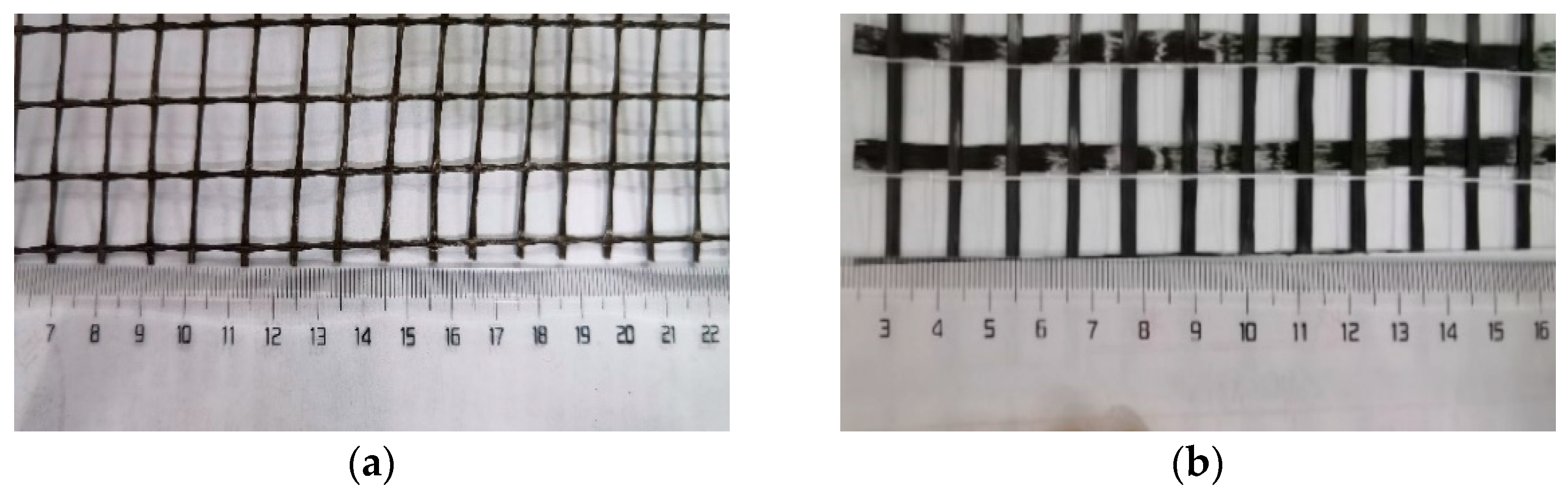
| PE fiber | 0.97 | 2900 | 116 | 2.42 | 31 | 12 | - |
| BFRP gridding cloth | 1.9 | 1700 | 80 | 2.16 | - | - | 10 |
| CFRP gridding cloth | 1.8 | 3400 | 240 | 1.6 | - | - | 10 |
| Materials | Cement | Silica Fume | Fly Ash | Quartz Sand | Water Reducing Admixture | Water Cement Ratio | Fiber Content |
|---|---|---|---|---|---|---|---|
| PE-ECC | 390 | 50 | 850 | 460 | 6 | 0.24 | 2% |
| Cement matrix | 500 | - | - | 1500 | 0.6 | 0.4 | - |
| TRECC | TRECC-NC | |||
|---|---|---|---|---|
| Uniaxial Tension | Three-Point Bending | Uniaxial Tension | Three-Point Bending | |
| No FRP | TRECC0 | TRECC1 | TRECC0-NC | TRECC1-NC |
| BFRP | B-TRECC0 | B-TRECC1 | B-TRECC0-NC | B-TRECC1-NC |
| CFRP | C-TRECC0 | C-TRECC1 | C-TRECC0-NC | C-TRECC1-NC |
| Specimen Name | Bending Specimen Roughness | Tensile Specimen Roughness | Type of FRP | PE Fiber (%) | Freeze–Thaw Times/Times |
|---|---|---|---|---|---|
| 0 | - | - | - | - | 0~300 |
| No roughness | 0 | 0 | - | 2 | 0~300 |
| Low roughness | 0.104 | 0.056 | BFRP | 2 | 0~300 |
| High roughness | 0.247 | 0.103 | CFRP | 2 | 0~300 |
| Freeze–Thaw Cycles | Influencing Factor | Peak Load without Roughness/kN | Peak Load under Low Roughness/kN | Peak Load under High Roughness/kN |
|---|---|---|---|---|
| 0 cycle | TRECC1-NC | 2.81 | 3.42 | 3.92 |
| B-TRECC1-NC | 3.69 | 4.36 | 5.36 | |
| C-TRECC1-NC | 4.01 | 5.12 | 6.01 | |
| 100 cycles | TRECC1-NC | 2.96 | 3.74 | 4.02 |
| B-TRECC1-NC | 3.76 | 4.51 | 5.51 | |
| C-TRECC1-NC | 4.11 | 5.6 | 6.19 | |
| 200 cycles | TRECC1-NC | 2.21 | 3.01 | 3.52 |
| B-TRECC1-NC | 2.96 | 3.82 | 4.98 | |
| C-TRECC1-NC | 3.26 | 4.73 | 5.36 | |
| 300 cycles | TRECC1-NC | 1.21 | 2.03 | 2.51 |
| B-TRECC1-NC | 1.66 | 2.53 | 3.42 | |
| C-TRECC1-NC | 1.98 | 3.36 | 3.97 |
Disclaimer/Publisher’s Note: The statements, opinions and data contained in all publications are solely those of the individual author(s) and contributor(s) and not of MDPI and/or the editor(s). MDPI and/or the editor(s) disclaim responsibility for any injury to people or property resulting from any ideas, methods, instructions or products referred to in the content. |
© 2023 by the authors. Licensee MDPI, Basel, Switzerland. This article is an open access article distributed under the terms and conditions of the Creative Commons Attribution (CC BY) license (https://creativecommons.org/licenses/by/4.0/).
Share and Cite
Xu, F.; Li, Q.; Ma, T.; Zhang, Y.; Li, J.; Bai, T. Insight into the Mechanical Performance of the TRECC Repaired Cementitious Composite System after Exposure to Freezing and Thawing Cycle. Buildings 2023, 13, 1522. https://doi.org/10.3390/buildings13061522
Xu F, Li Q, Ma T, Zhang Y, Li J, Bai T. Insight into the Mechanical Performance of the TRECC Repaired Cementitious Composite System after Exposure to Freezing and Thawing Cycle. Buildings. 2023; 13(6):1522. https://doi.org/10.3390/buildings13061522
Chicago/Turabian StyleXu, Fei, Qi Li, Tongze Ma, Yao Zhang, Junwei Li, and Tao Bai. 2023. "Insight into the Mechanical Performance of the TRECC Repaired Cementitious Composite System after Exposure to Freezing and Thawing Cycle" Buildings 13, no. 6: 1522. https://doi.org/10.3390/buildings13061522