Article

Study on the Eccentric Compressive Performance of Steel Fibre Reinforced Coal Gangue Concrete Columns

School of Civil Engineering, Jilin Jianzhu University, Changchun 130118, China
*
Authors to whom correspondence should be addressed.
Buildings 2023, 13(5), 1290; https://doi.org/10.3390/buildings13051290
Submission received: 8 April 2023 / Revised: 5 May 2023 / Accepted: 13 May 2023 / Published: 16 May 2023
(This article belongs to the Special Issue Sustainability and Resiliency of Building Materials and Structures)

Abstract

:
Coal gangue is the waste created in the coal mining process and can be utilised as a coarse aggregate in construction projects to solve the environmental problems it causes. To study the mechanical properties of steel fibre reinforced coal gangue concrete (SFCGC) columns under eccentric compression, two natural aggregate concrete (NAC) columns and eight SFCGC columns were designed and fabricated for eccentric compression loading tests. The variables involved in the tests include gangue substitution rate (0%, 30%, 50%, 70%), steel fibre volume content (SFVC) (0%, 0.5%, 1%, 1.5%), and eccentricity (0.25, 0.5). The experimental work and theoretical analysis were used to investigate the failure mode, cracking, and ultimate bearing capacity of SFCGC columns. The effects of various variation parameters on the longitudinal strain, concrete strain, transverse displacement, crack width, and bearing capacity were analysed in detail. The digital image correlation (DIC) technique was used to compare with the conventional observation and to analyse the cracking trend of the specimens. The testing results revealed that the damage pattern of SFCGC columns under eccentric compression was similar to that of NAC columns. The eccentricity significantly affected the damage pattern (or bearing capacity) of SFCGC columns. The effect of the coal gangue replacement rate on the lateral displacement corresponding to the ultimate load can be neglected under the same eccentricity. The incorporation of steel fibres effectively inhibited the development of cracks in the columns, with an average increase in crack load and ultimate load of 7.36% and 17.1%. The equations were also established to determine the crack width and bearing capacity of the studied SFCGC columns, and the theoretical predictions agreed with the experimental results.

1. Introduction

As the world’s second-largest energy source and China’s number one, coal’s tremendous production has led to an impressive output of its derivative, coal gangue. According to statistics, China’s production of raw coal in 2021 is as high as 4.13 billion tons, an increase of 5.9%, and the production of coal gangue is about 743 million tons, an increase of 5.84% [1,2]. The accumulation of coal gangue seriously affects human health, safety, and the ecological health of the environment [3]. Therefore, developing a comprehensive utilisation strategy for coal gangue and eliminating its negative environmental impact is urgent [4,5]. At the same time, concrete structures, the most widely used building structures, have had a significant negative impact on the environment due to their construction size with the development of urbanisation and industrialisation [6]. The main reason includes the consumption of natural resources (including aggregate, water, etc.) during construction [7]. The shortage of aggregates is the most significant, accounting for 75–80% of the volume of concrete [8]. Coarse aggregates are mainly obtained by blasting rock boulders and then crushing them to the required size, a process harmful to the environment as it destroys mountains, erodes the soil, and produces large amounts of carbon dioxide. As a result, coal gangue has entered the minds of researchers as one of the possible alternatives to coarse aggregates.
The replacement of crushed stone with coal gangue for concrete production can consume large amounts of coal gangue and reduce the use of crushed stone, which is beneficial to the development of eco-friendly construction materials and fulfils the purpose of protecting the natural environment [9,10]. With its stable structure and low reactivity, coal gangue must be activated by mechanical grinding and thermal and chemical activation methods for construction applications [11,12]. Sun and Li [13] explored the use of coal gangue concrete for gob-side entry retaining, which addressed both ecological and resource shortages, decreased the overall cost of filling materials and raised the economic efficiency of coal mining enterprises. Wang and Zhao [14] demonstrated that coal gangue could satisfy the compressive strength requirements of concrete aggregates by testing the basic physical and mechanical properties of coal gangue aggregates. Ma [15] showed that coal gangue concrete has good resistance to sulphate. As a coarse aggregate, coal gangue provides both higher compressive strength and durability in alkali-active gangue-slag concrete for chemically aggressive environments such as sulphate or chloride. Li [16] prepared high closed porosity foamed ceramics with good thermal insulation properties by using coal gangue. Qiu [17] et al. analysed the mechanical properties of coal gangue concrete under the freeze-thaw environment. They presented the evolutionary model and the intrinsic structure relationship of its freeze-thaw damage. Xiao et al. [18] discovered that when coal gangue was used as an aggregate, the concrete’s compatibility in tensile strength continued to decrease as the amount of coal gangue increased. Liu et al. [19] suggested a prediction model for the modulus of elasticity of coal gangue concrete. The performance of coal gangue concrete significantly reduces when the coal gangue substitution rate is too large [20,21]. Zhu et al. [22] revealed that when the replacement rate of coal gangue exceeded 50%, it would result in a rapid decrease in the compressive strength of coal gangue concrete. Chen [23] illustrated that the 28-day compressive strength of C25 concrete with a 100% coal gangue replacement rate was 25.47% less than that of ordinary crushed stone concrete. Guan et al. [24] studied that the compressive strength of CGC was decreased by 21.2% when the replacement rate of coal gangue was 60%, while when the replacement rate of coal gangue was less than 40%, it had no significant effect on the strength of CGC.
As a structural material invented in 1874, steel fibres have been widely used in construction applications [25] for their ability to dramatically improve the mechanical properties of concrete, such as impact strength, toughness, flexural and tensile strength, ductility, and resistance to cracking and spalling [26]. In this case, however, there is still extensive research value in steel fibres [27,28]. Li and Qin [29] observed that the mechanical summation of the shaped steel fibres in the concrete resulted in enhanced adhesion within the member. When the volume content of steel fibres in concrete was 0–2%, the steel fibre-matrix adhesion properties increased with the increasing volume content of steel fibres [30]. In addition, steel fibres improve the protective layer-core zone, effectively confining the concrete to the core of the reinforced concrete specimens, which benefits both the strength and ductility of the reinforced concrete specimens [31,32].
The strength of the concrete produced using coal gangue as coarse aggregate is similar to that of ordinary concrete. Still, its durability is lower than ordinary concrete’s and prone to brittle damage [33,34]. Liu et al. [35] found that gangue concrete columns eccentrically stressed were unable to prevent the expansion of cracks effectively and were prone to cracking and corrosion of reinforcement when conducting a study on gangue concrete columns. Luo et al. [36] revealed that the integration of steel fibres in the concrete with coal gangue as coarse aggregate is beneficial to its frost resistance. Wang et al. [37] discovered that the incorporation of steel fibres could significantly change the brittleness of coal gangue vitrified light aggregate concrete. Thus, adding steel fibres to coal gangue concrete can improve its properties and suitability for construction.
Digital Image Correlation (DIC) has the advantages of high accuracy, non-contact measurement, no special requirements for the environment, and the ability to give information on the deformation of a specimen in any area and in any direction during loading, and is therefore widely used in the fields of solid mechanics and applied physics, and is now gradually being applied to research on construction materials. The accuracy of DIC in testing the uniaxial compressive strain and crack opening displacement of specimens was verified by Dinh et al. [38] and Yu et al. [39] using strain gauges and displacement gauges, respectively. An objective of this test was to use DIC to monitor the development of cracks in concrete columns at different loading stages at mid-height and to extract data on the vertical displacement and mid-span deflection of the specimens and, in this way, compensate for possible errors in the contact measuring instruments.
Most of the current research on coal gangue remains in the field of physical and chemical properties of the material, while there is a lack of research on the mechanical performance testing of concrete specimens. People’s knowledge of the performance of coal gangue concrete applied to actual buildings is relatively incomplete as compared to other mature materials. In particular, the study of SFCGC columns has not been reported. Therefore, this paper subjected ten SFCGC columns to eccentric compression tests with coal gangue replacement rate, steel fibre volume admixture, and eccentric distance as the main parameters. The performance of the specimens was studied and verified using current structural codes, proving the applicability of the current codes to SFCGC columns, which provides theoretical support for mitigating environmental problems through the promotion of coal gangue applications.

2. Materials and Methods
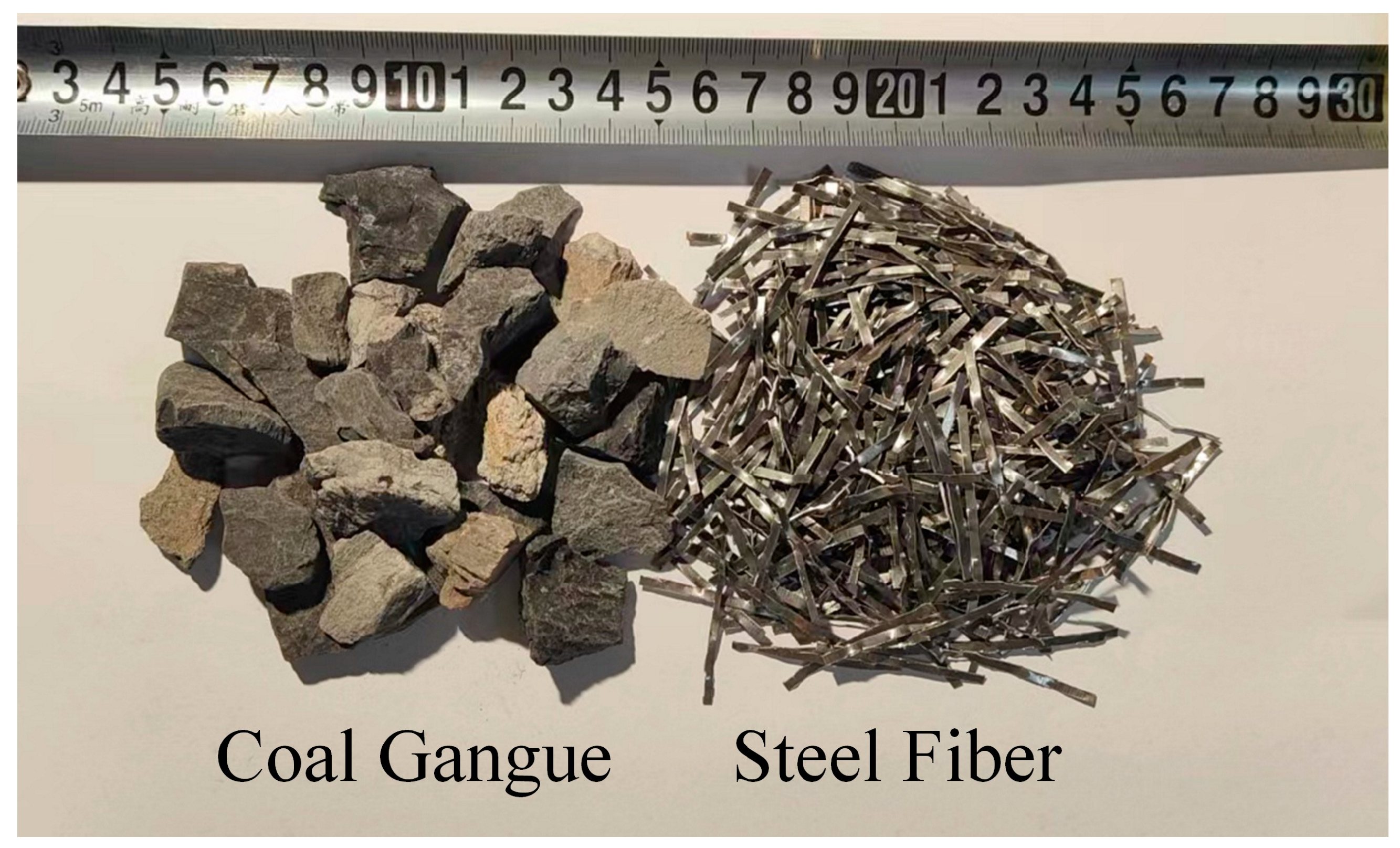
2.1. Raw Materials

JGJ51-2002 [40] is a test used to design the coal gangue concrete used in the test with design strength C30. SFCGC is formulated from coal gangue aggregate, silicate cement, shear wavy steel fibre (as shown in Figure 1, physical properties in Table 1), and tap water. P-O42.5 ordinary silicate cement was selected according to specification GB 175-2020 [41], and its chemical and physical properties are shown in Table 2 and Table 3. The chemical composition of coal gangue is shown in Table 4.

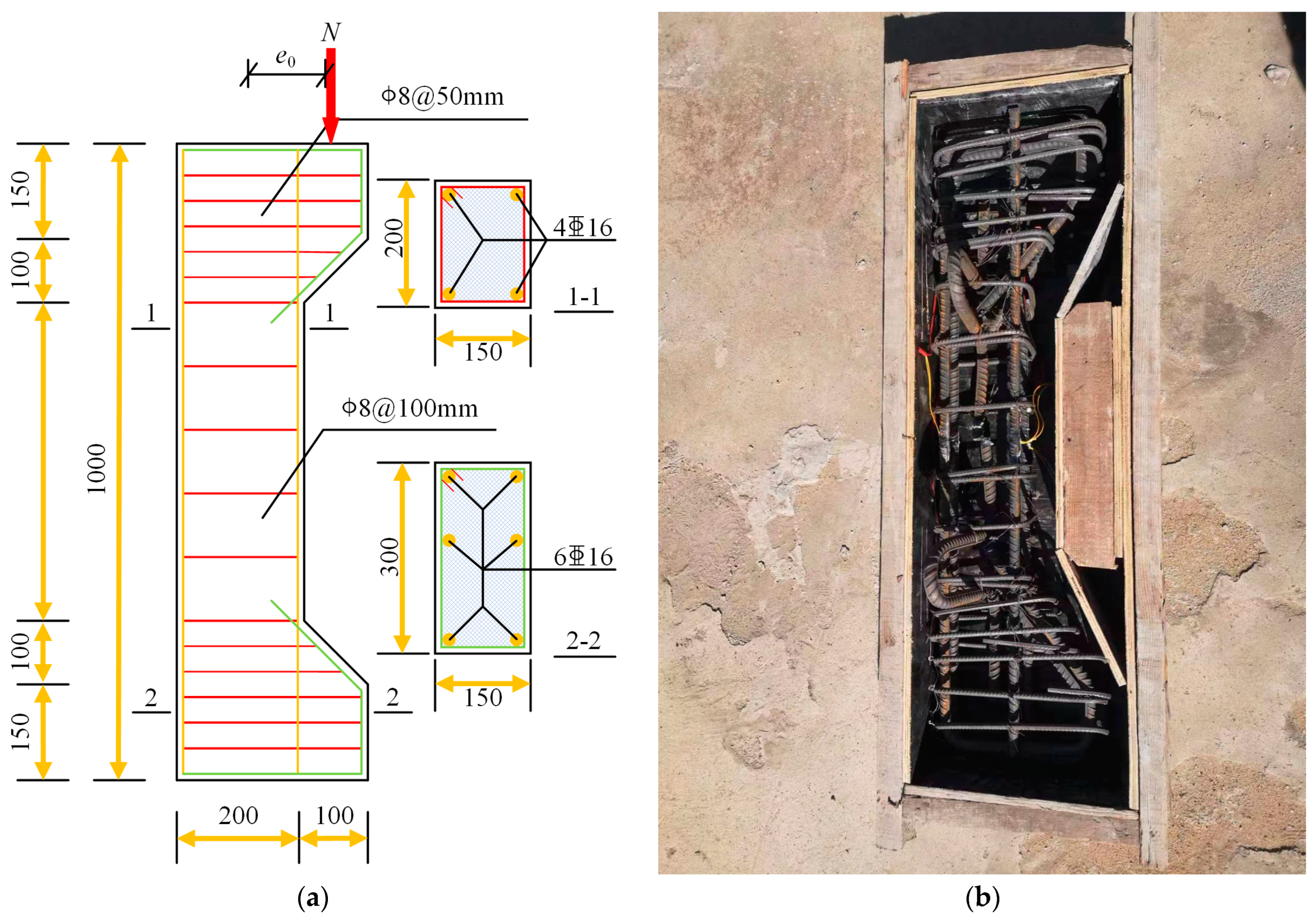
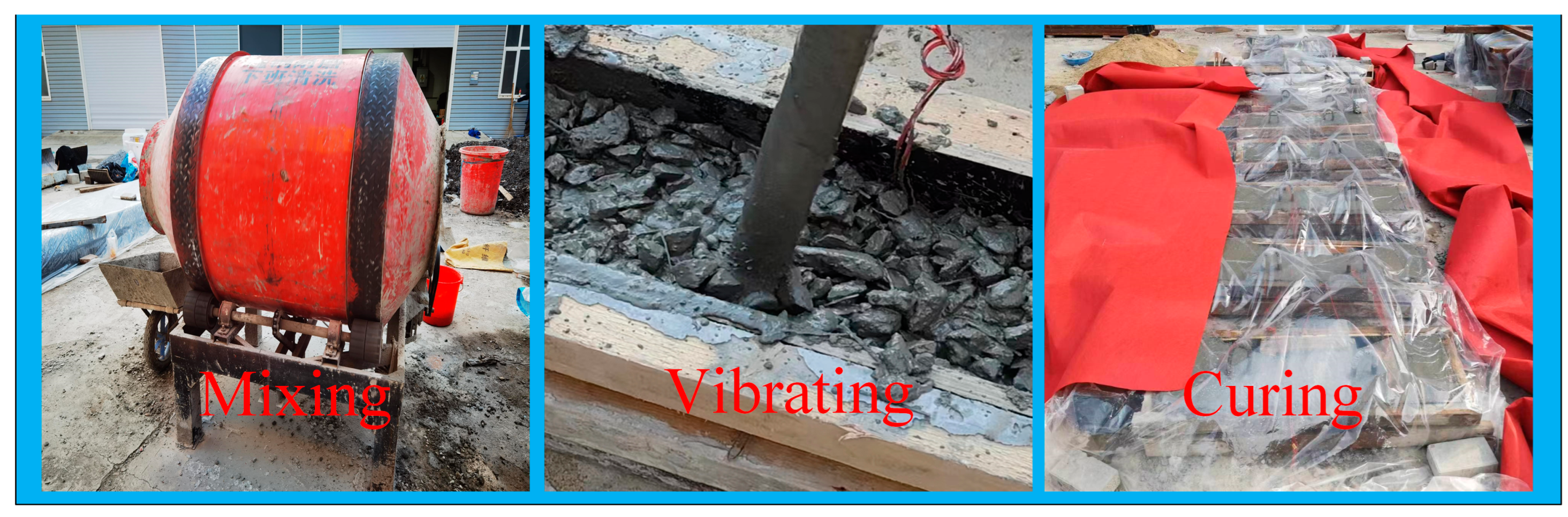
2.2. Preparation of SFCGC Columns

Ten specimens were designed concerning specification GB50010-2010 [42], where the system variable parameters considered included two eccentricities (0.25, 0.5), four gangue replacement rates (0%, 30%, 50%, 70%), and four steel fibre volume contents (0%, 0.5%, 1%, 1.5%). The design parameters for the specimens are listed in Table 5.
The cross-section of all specimens is 200 mm × 150 mm, and the height is 1000 mm. All samples contained the same reinforcement: a longitudinal reinforcement of 16 mm in diameter with a yield strength of 417 MPa for HRB400 grade bars and hoop bars of 8 mm in diameter with a yield strength of 346 MPa for HPB300 bars. Figure 2 displays the detailed dimensions of the column specimens, the reinforcement configuration and the fabricated solid reinforcement cage, respectively. As shown in Figure 2b, the reinforcement was strictly assembled according to the set specifications while the wooden formwork was built, and finally, the assembled reinforcement cage was placed into the wooden formwork. Then, concrete was poured into the formwork and fully compacted with a vibrator to ensure uniform concrete dispersion. The concrete fabrication process is shown in Figure 3. While pouring the specimens, 150 mm × 150 mm cubic specimens were made from the same concrete batch. After three days, the specimens were de-moulded and immediately placed in a maintenance room at a temperature of 22 ± 2 °C and a relative humidity of 95 ± 5% for 28 days.

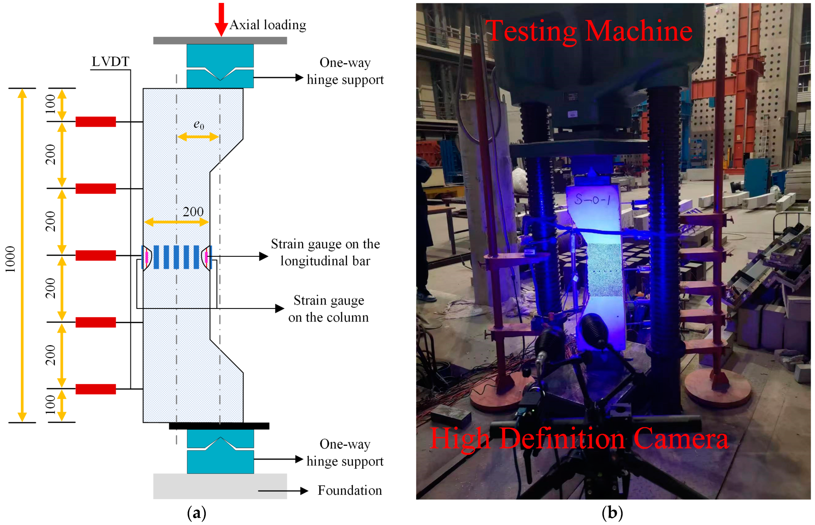
2.3. Test Preparation

2.3.1. Location of Measurement Points

In the test, three strain gauges were evenly distributed at the middle height of the compressive and tensile sides of the specimens to measure the concrete strain. Five strain gauges were evenly distributed at the middle height of the bottom surface of each specimen to verify whether the cross-sectional strain at the middle height of the specimen complied with the plane cross-section assumption. Five displacement meters are evenly placed along the vertical direction on the tensioned side of the bias column, with the outermost displacement meter 100 mm from the top and bottom. Two strain gauges are arranged in the middle of each longitudinal bar. Two strain gauges are arranged in the middle of each longitudinal bar. The layout of the displacement and strain gauges is depicted in Figure 4a. Referring to the setup of Lin et al. [43], two one-way hinge supports were placed on the top and bottom of the specimen in contact with the press, as shown in Figure 4a.

2.3.2. Preparation for DIC

A non-contact optical measurement method based on digital image correlation (DIC) was applied to the other side of the specimen surface, as shown in Figure 4b. The scattered spots of global strain measurement are made on the specimen’s front surface, and the diameter of the scattered spots is about 0.8 mm, covering the whole area in which the test is to be performed. A high-definition camera was used for image acquisition in this area, and the capture frequency was 1 s/time. By comparing the changes in the relative positions of these scattered spots during the loading process, the displacement field on the surface of the specimens can be calculated, and the strain distribution field can be further analysed. The strain field provided by the DIC can be verified and enhanced with the strain data gained from the strain gauge to uncover the details of deformation.

2.3.3. Test Loading Scheme

The compression tests of all the specimens in this research were conducted on the model NYL-500t hydraulic-type compression tester with a maximum load of 5000 kN. The arrangement and photos of the loading device are shown in Figure 4b. A load of 2 kN is preloaded on the specimens to check the correct operation of the strain gauges, displacement meters, loading apparatus, and data acquisition system. Then, reloading starts from 0 with the loading control first. During the initial loading phase, the loading hold time for each phase was 10 min. During this period, the development of concrete cracks was observed and recorded. As the load approaches the ultimate load, it is gradually loaded until it reaches the upper limit of the sample.

3. Experimental Results
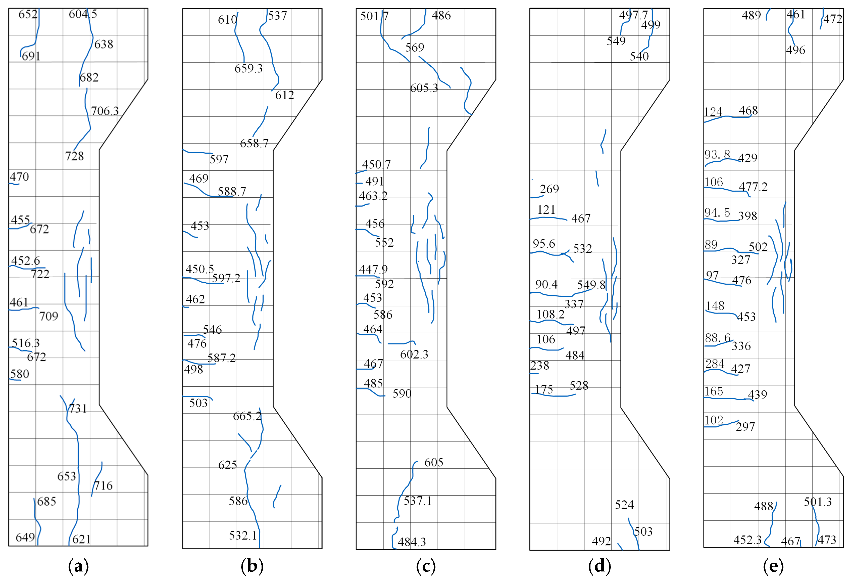
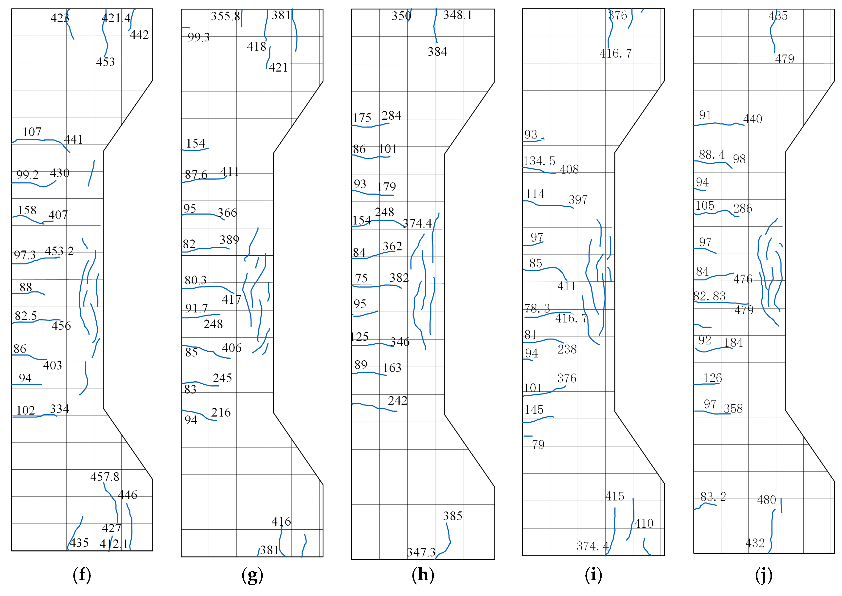
3.1. Failure Modes

The crack morphology of the specimens under different eccentricity loading is shown in Figure 5. Figure 6 shows the crack development of specimens with different coal gangue replacement rates under large eccentric loading obtained by DIC system analysis. Each specimen is extracted with its nephogram at 0.2 Nu, 0.4 Nu, 0.6 Nu, and 0.8 Nu, respectively.
Specimens S-0-1, S-30-1, and S-50-1 were loaded under small eccentric loads. At 65% of the ultimate load, three–four transverse cracks appear in the tensile zone. At 30% of the ultimate load, the number of cracks gradually increases, and the length and width of the existing cracks develop slowly. At 80% of the ultimate load, longitudinal cracks appear in the compression zone. At 90% ultimate load, the transverse crack stretched to the neutral axis of the test column, the crack width became larger, and the transverse displacement kept increasing. When the ultimate load is reached, many longitudinal cracks appear in the compression zone, while the specimens emit a crisp cracking sound. The load is then rapidly reduced, and the specimens are destroyed.
Specimens L-0-1, L-30-1, L-50-1, L-70-1, L-50-0, L-50-0.5, and L-50-1.5 were loaded under a large eccentric load. At 20% ultimate load, transverse cracks appeared in the tensile zone of the test column, and an increase in the width and length of the transverse cracks accompanied the increase in load. With the continued loading of up to 90% of the ultimate load, longitudinal cracks appeared in the compression zone, and transverse cracks penetrated. The strain nephogram agrees well with the crack development under conventional observation, which verifies the reliability of DIC in examining crack development.
Notably, all specimens had no major crushing and spalling of the concrete in the compressed area, maintaining its integrity due to the binding of the steel fibres and the action of the bridge.

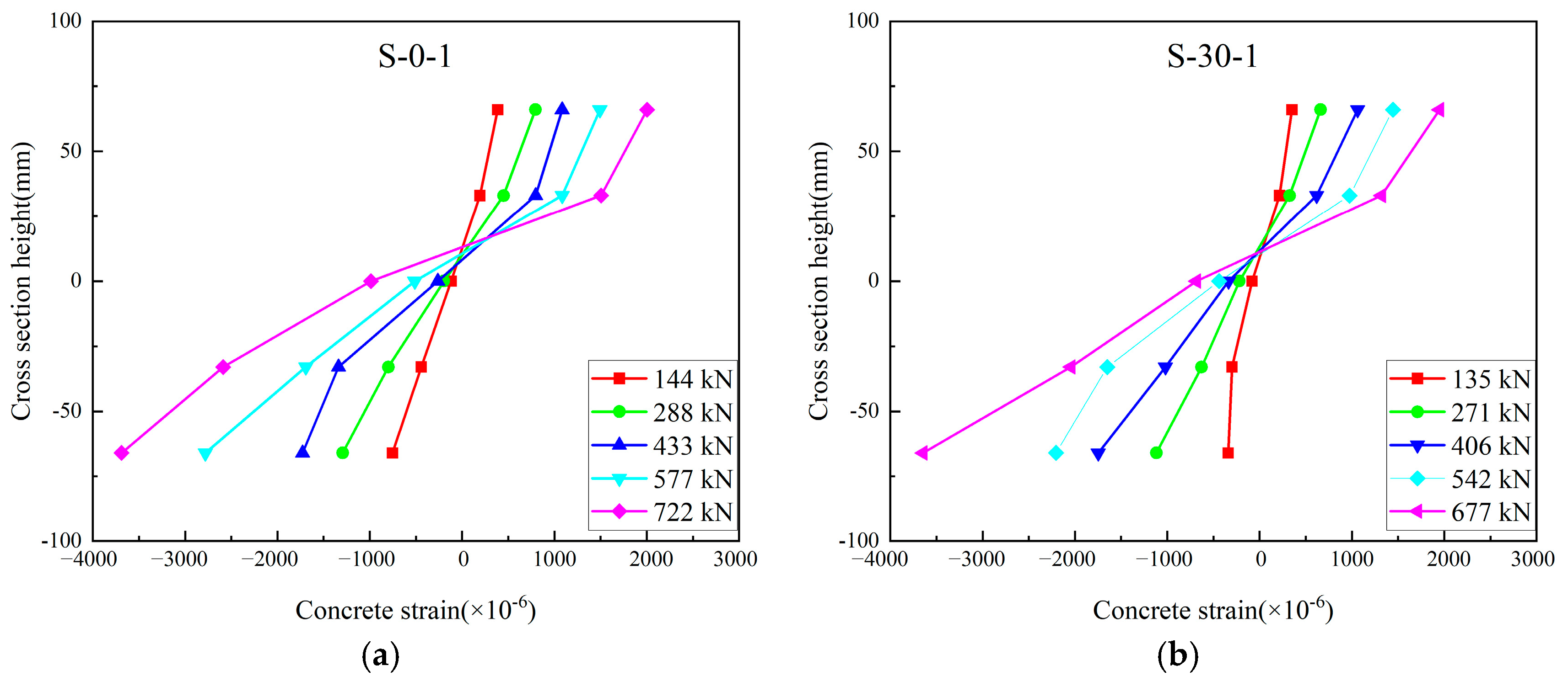
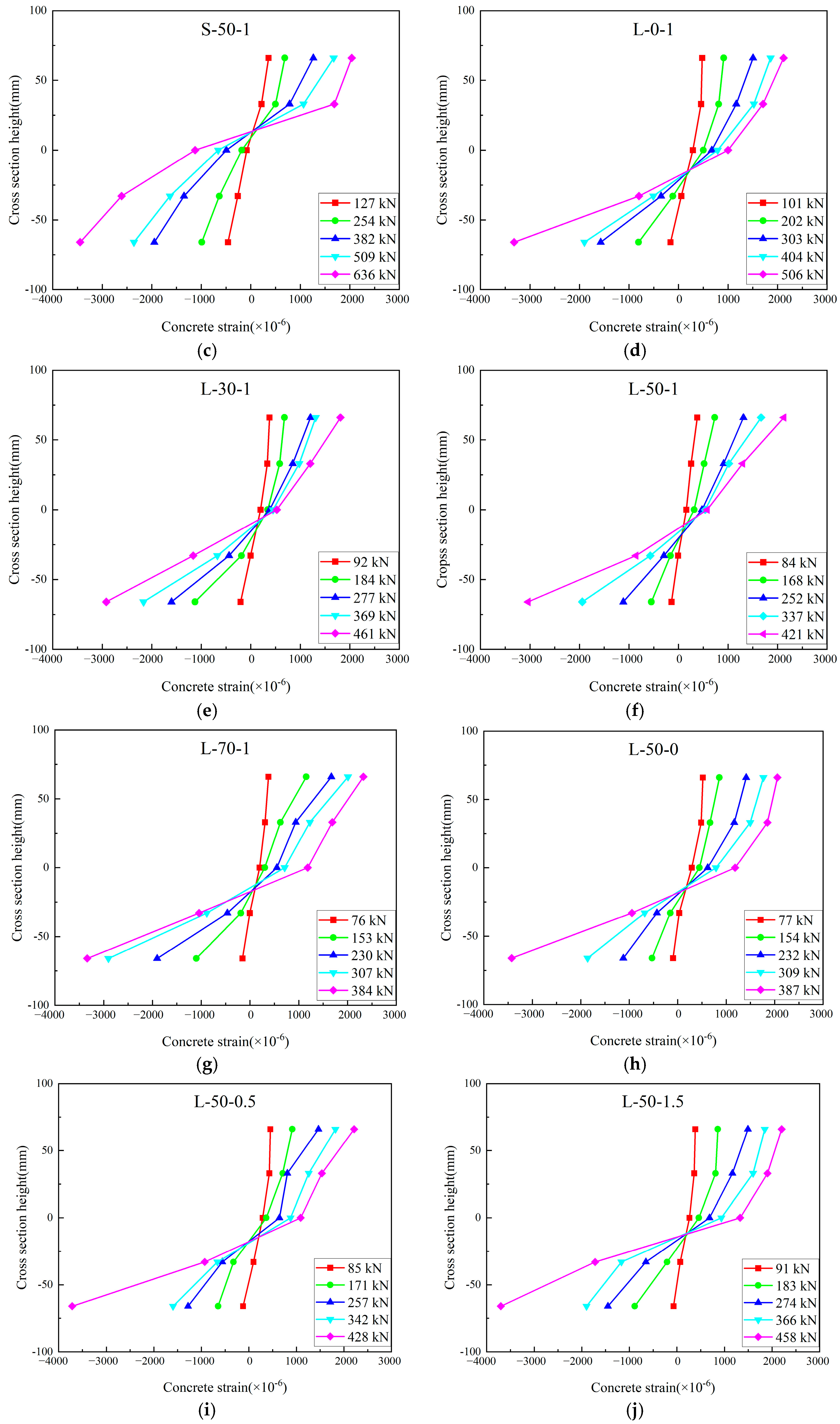
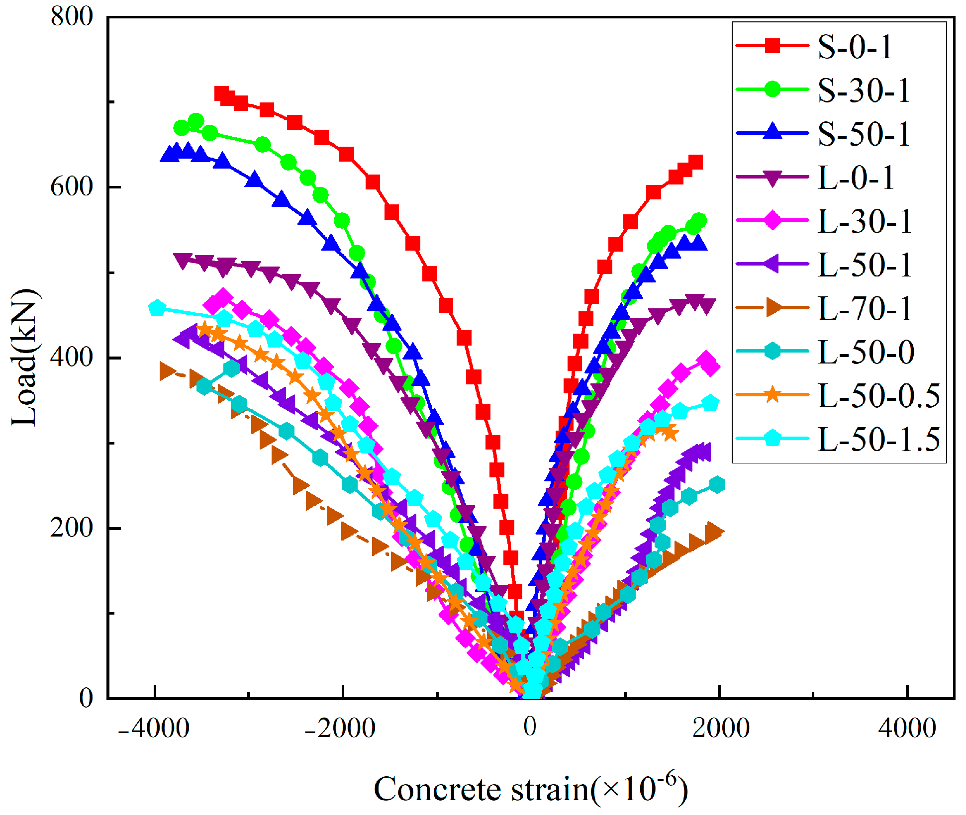
3.2. Concrete Strain of the Mid-Height Section

Figure 7 illustrates the strain distribution of concrete in the middle height section of the specimen at different loading stages. During the loading process, the average strain in the cross-section is almost linearly distributed, and the depth of the neutral axis gradually moves toward the compression edge as the applied load increases. This phenomenon confirms that the deformation of the SFCGC column section follows the plane cross-section assumption.

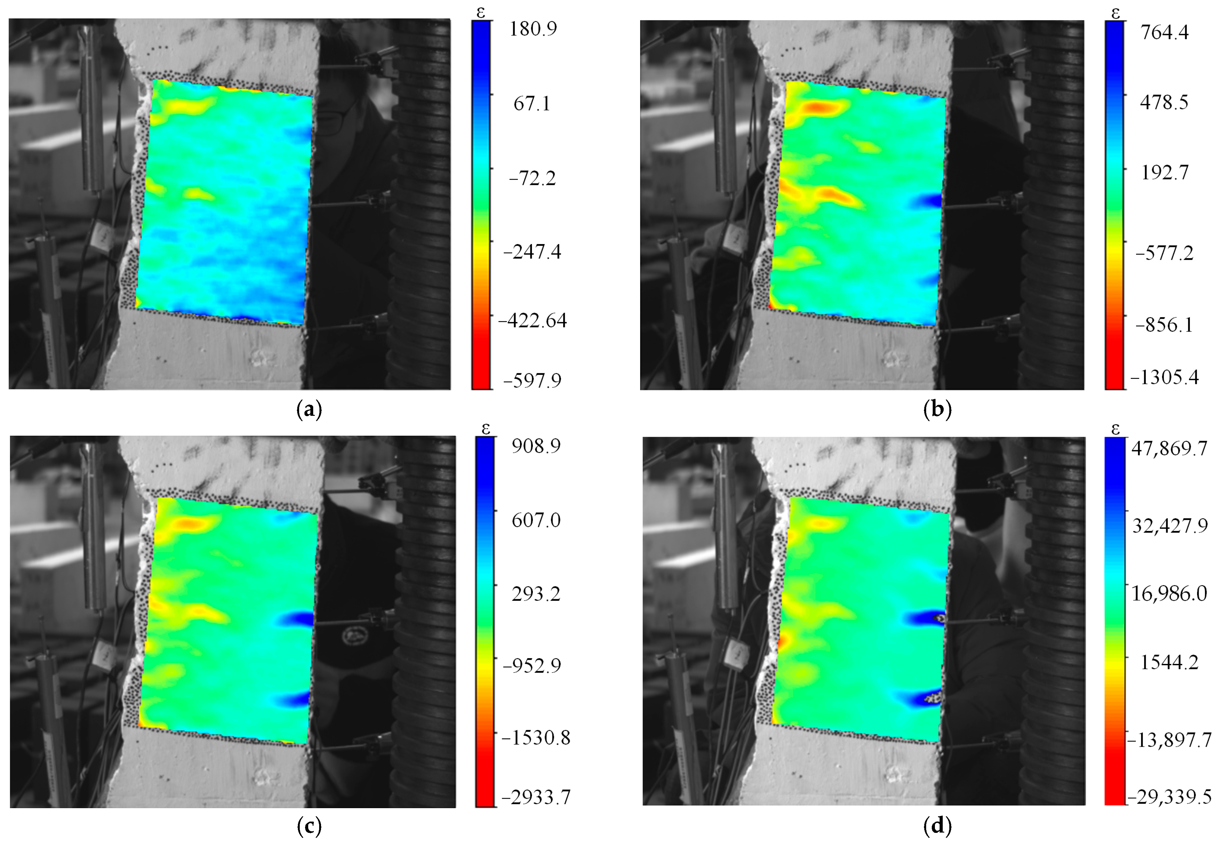
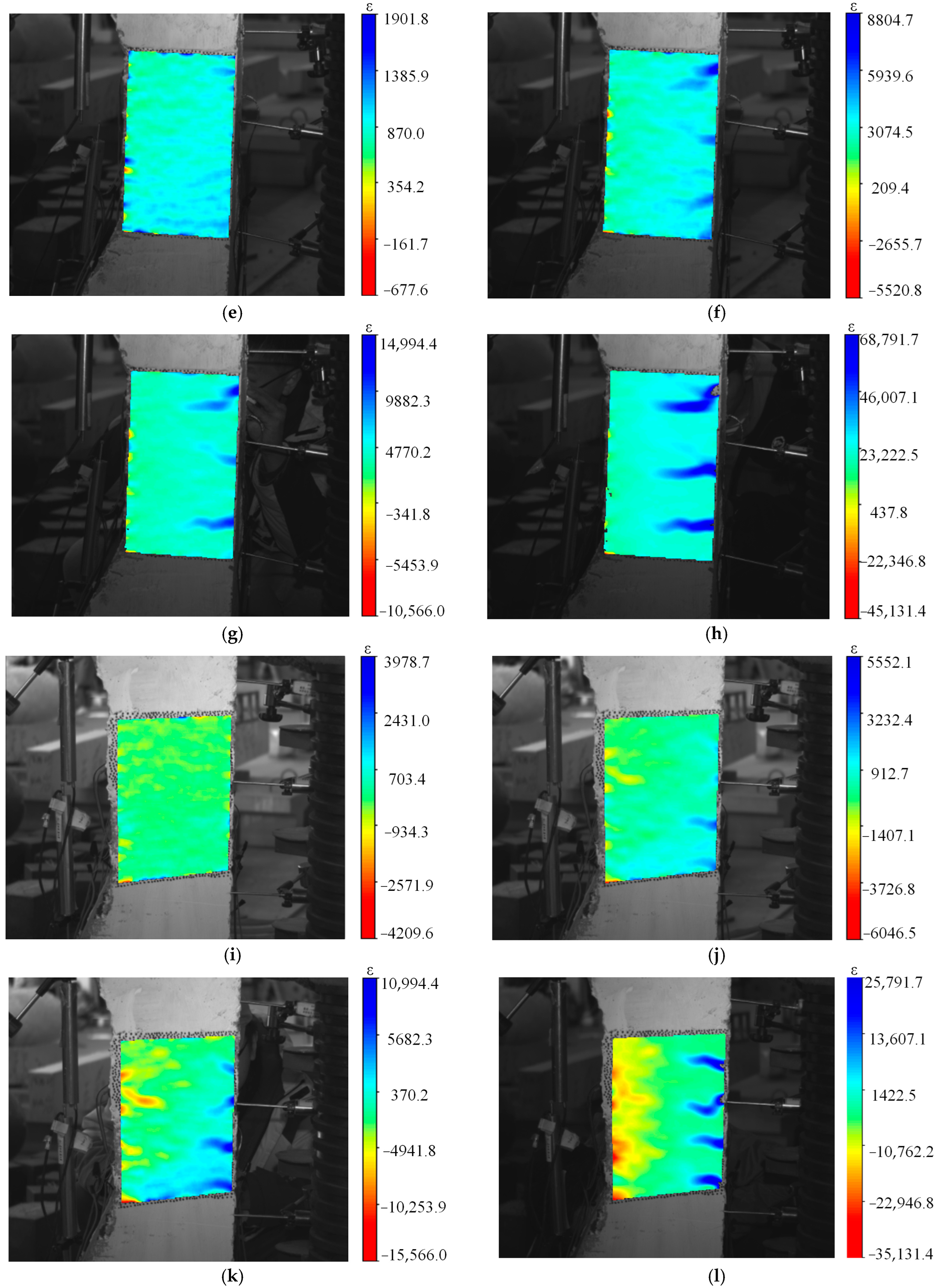
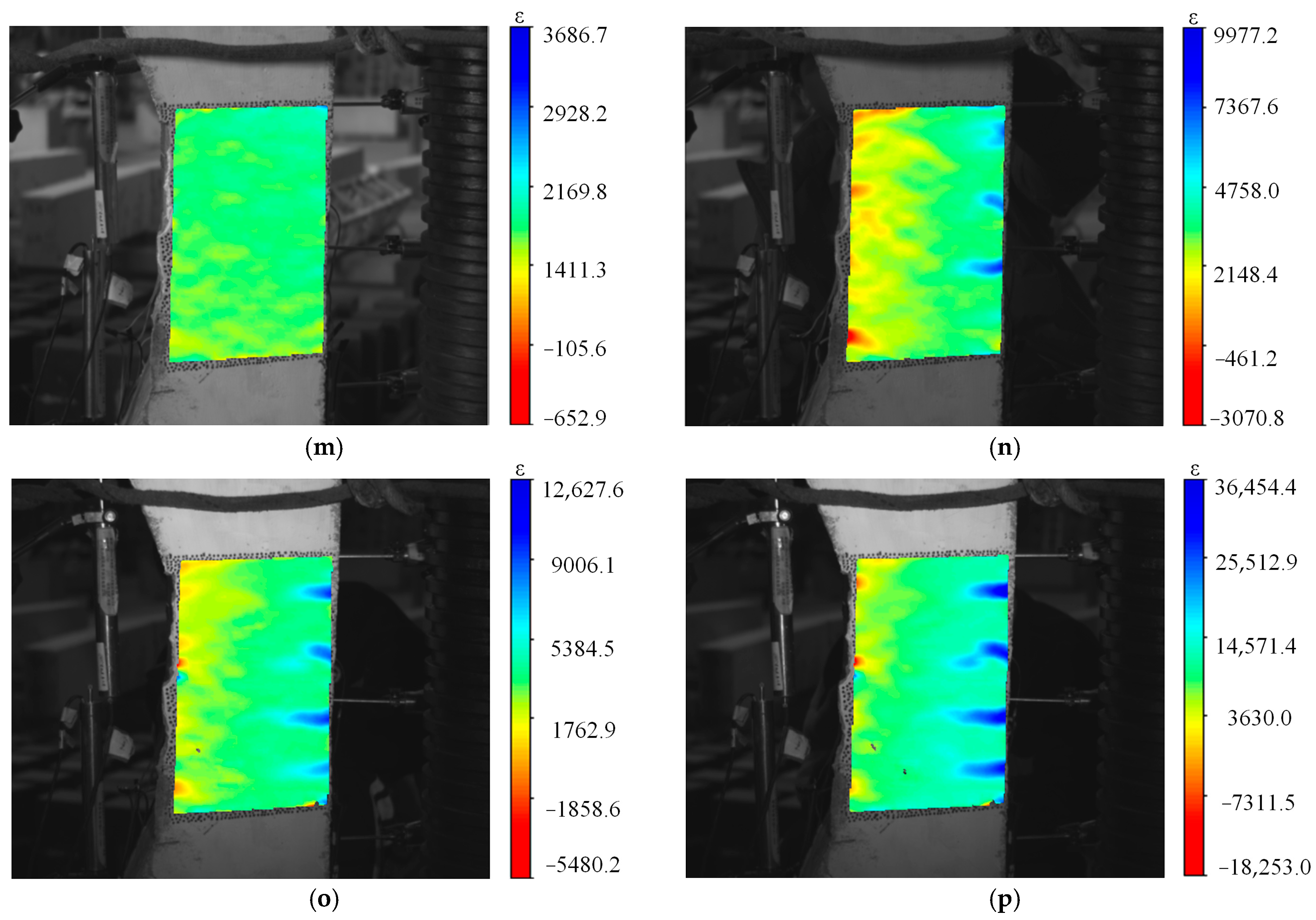
3.3. Strains of the Concrete

Based on the experimental test results, the load-concrete strain curves of eccentrically compressed SFCGC columns with different conditions were plotted, as shown in Figure 8. Under the same residual conditions, the concrete deformation of the specimens was greater with an increase in the coal gangue replacement rate. At the same time, the increase in steel fibre admixture also led to the same results as the former one. This is because the coarse aggregate of the gangue has mechanical properties that increases deformation, while the steel fibres have a certain anti-cracking function, which improves the deformation capacity of the specimen, while this also corresponds to the conclusions reached in the paper [44] on the role of steel fibres.

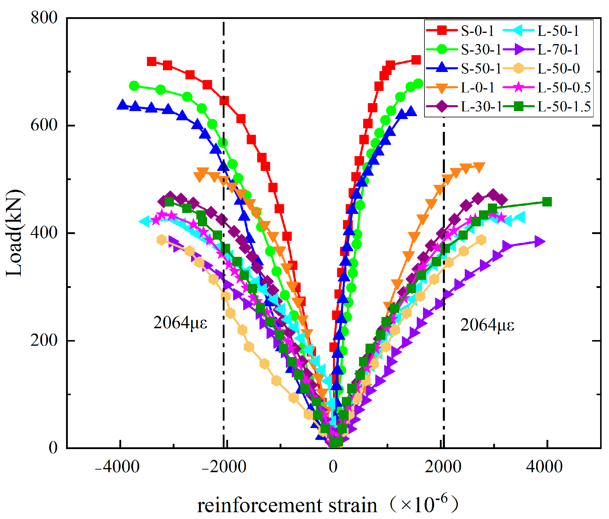
3.4. Strains of the Longitudinal Steel Bars

Figure 9 provides the load-longitudinal strain curves of SFCGC columns under different conditions of eccentric compression. The Figure shows that the compressive reinforcement of the small eccentric compressive specimens has yielded when the load reaches the bearing capacity limit state. Moreover, its tensile reinforcement has not yielded yet. On the contrary, the compressive and tensile reinforcement of the large eccentric compressive specimen has yielded. This is consistent with the eccentric compressive damage characteristics.
The slope of the strain curve increases as the amount of steel fibres increases, and the strain on the reinforcement increases when the final load is reached, in agreement with the phenomenon obtained by reference [45], which is explained by the fact that the steel fibres present take up a portion of the tensile force when the concrete cracks, causing the stress on the reinforcement to decrease and the strain to increase at the same load level.

3.5. Load-Displacement Analysis

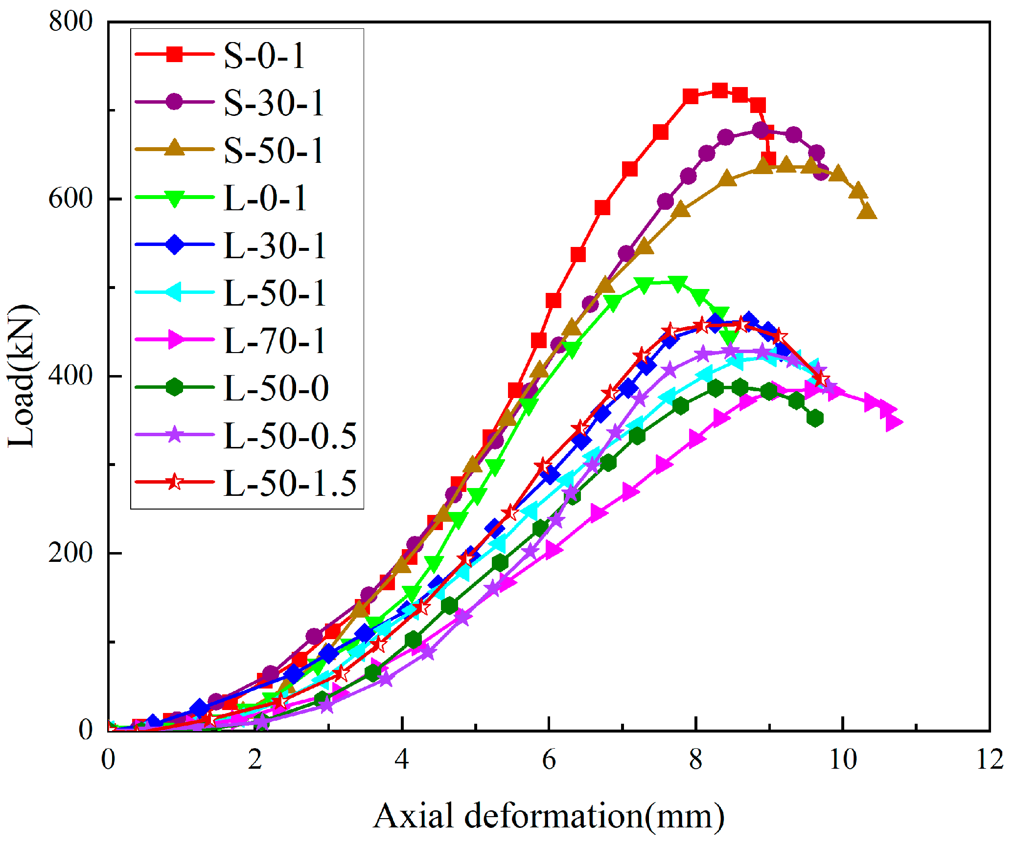
3.5.1. Load-Axial Displacement Analysis

The load-axial displacement curve of the specimens is shown in Figure 10. It can be seen that the axial displacement of the coal gangue concrete columns is proportional to the replacement rate of coal gangue. With an increase in gangue replacement rate, the maximum axial displacement of the member increases; this indicates that the gangue, as a coarse aggregate when its strength is low and easy to deform, characteristics directly affect the mechanical properties of the member not only reducing the ultimate bearing capacity of the columns but also increasing the axial deformation of the columns. From Figure 9, we can see that steel fibre has almost no effect on axial deformation, and the amount of coal gangue doping plays a dominant role in the axial deformation of the member.

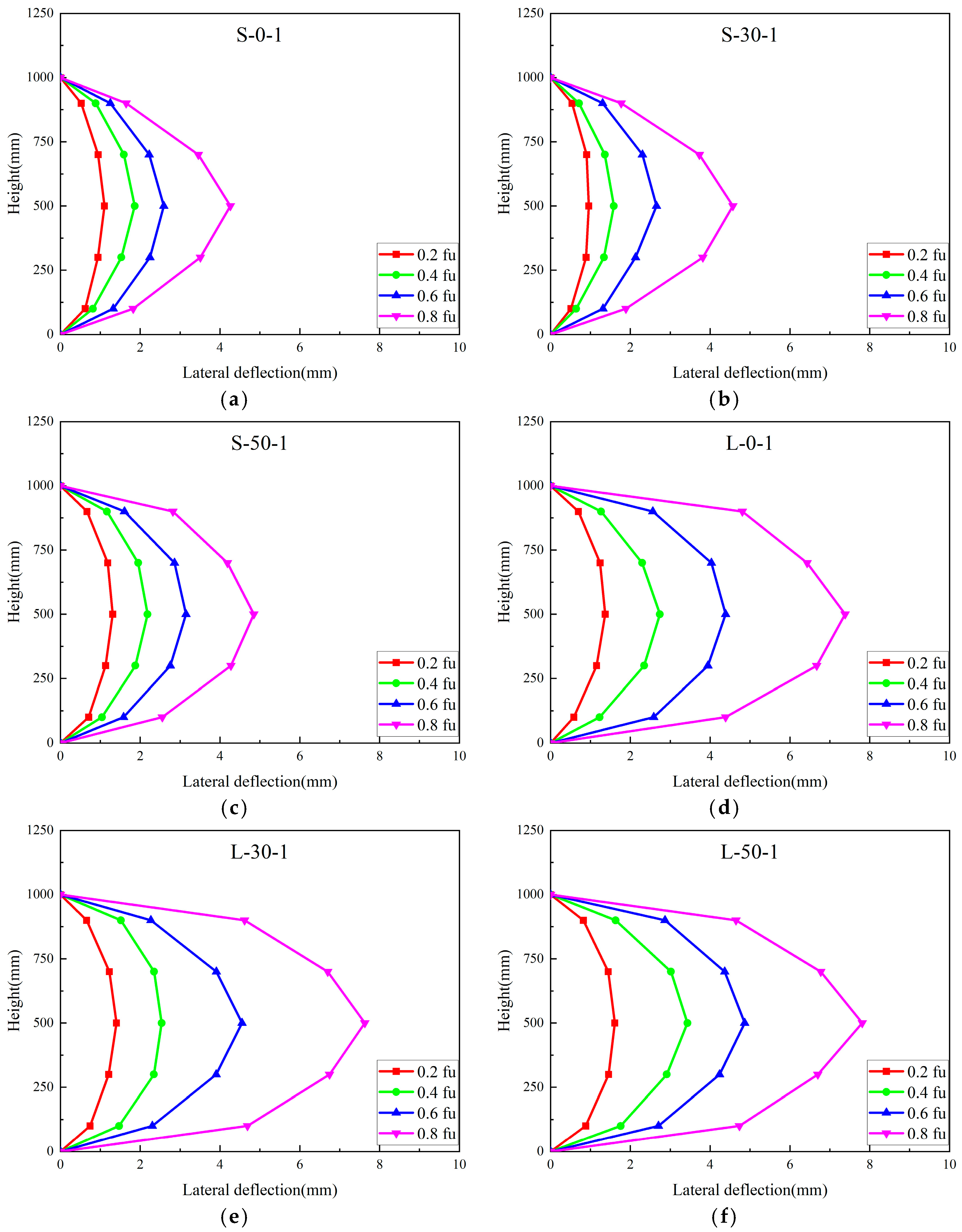
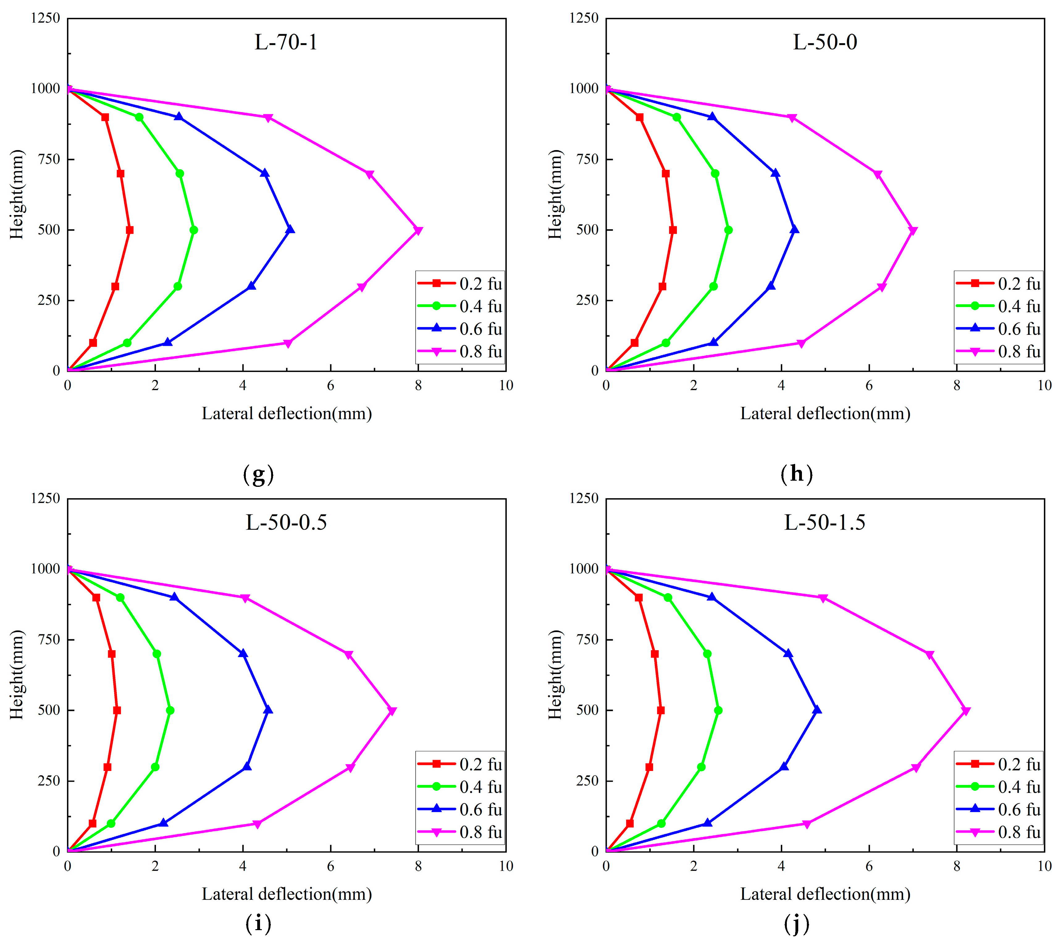
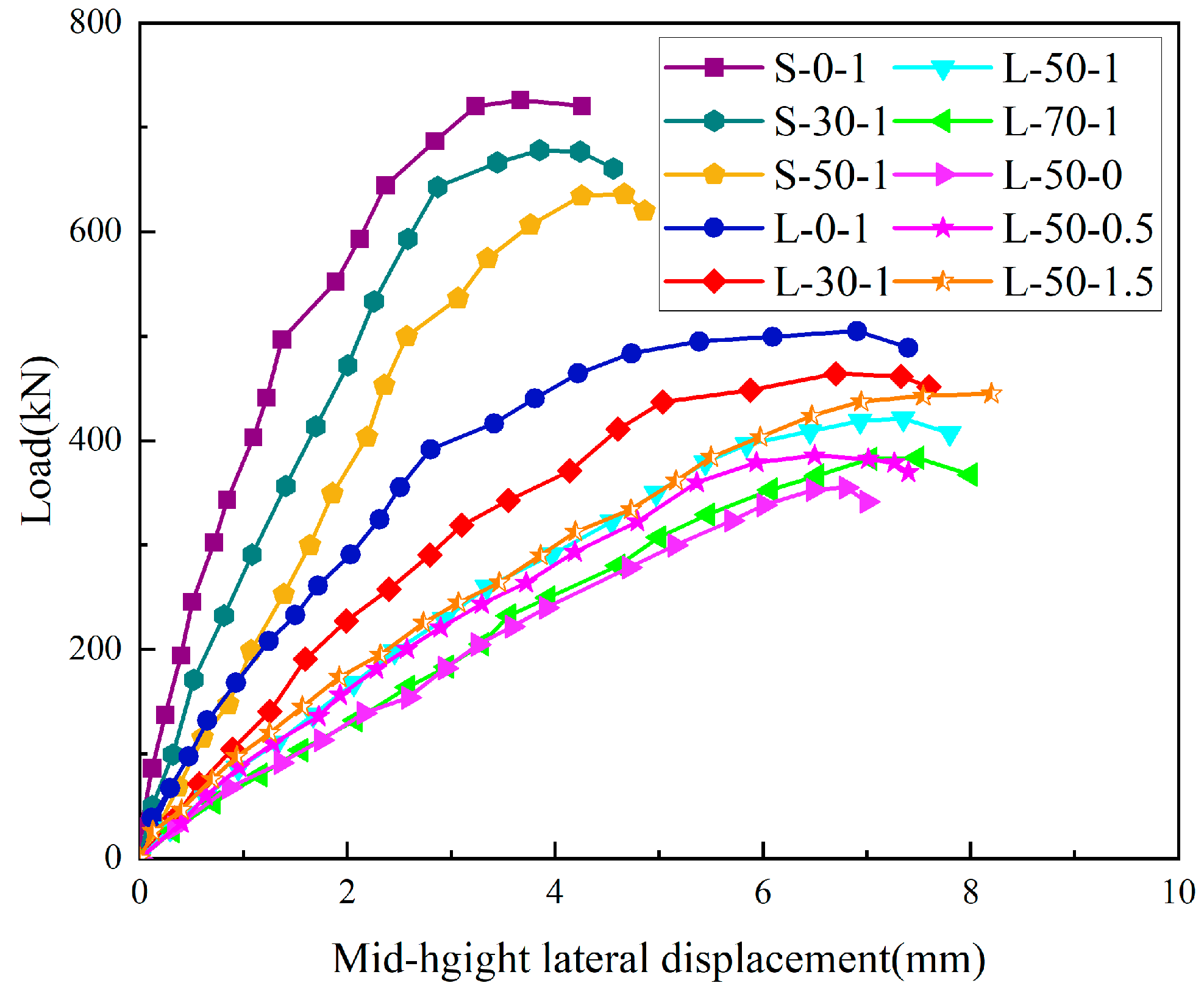
3.5.2. Load-Lateral Displacement Analysis

Figure 11 presents the lateral deflection curves of each specimen under different loading stages. The lateral deflection curves of the specimens are symmetrically distributed along the middle of the columns and approximate sinusoidal curves. As expected, the maximum lateral displacement occurred in the middle of the test columns, and the deformation was shaped like an arch.
The deflection curves of the middle height of the specimen are shown in Figure 12. From the Figure 12, it can be seen that the load-lateral deflection curves of the eccentrically stressed columns can be summarised into three stages:
  • In the elastic stage, although small cracks appeared on the tensile side of the specimens, the stiffness of the specimens did not drop significantly due to the presence of reinforcement and steel fibres which inhibited the development of cracks, and the curves were straighter.
  • In the plastic stage, as the load increases, the reinforcement gradually yields, the cracks expand faster, the stiffness of the specimens decreases, their lateral deflection increases nonlinearly, the slope of the curves decreases, and the specimens enter the plastic stage.
  • In the descending stage, after reaching the ultimate load, the load decreases, and the lateral deflection increases.
As can be seen from Table 6, in the case of the same coal gangue replacement rate and steel fibre admixture, the bearing capacity of the specimens when damaged under the large eccentric load is 24%, 23%, and 24.3% lower than the bearing capacity when damaged under the small eccentric damage load, respectively. The above phenomenon is because the eccentrically pressurised columns receive axial load and bending moment joint action. It can also be seen from Figure 11 that the flexural stiffness of the specimens decreases as the eccentricity increases.
In addition, the lateral displacement of the specimens increased with the elevated doping of the steel fibres. This is due to the bridging effect of the steel fibres, which improves the deformation capacity of the specimens.

3.6. Effect of Coal Gangue Replacement Rate on the Bearing Capacity of Specimens

Figure 13 shows the effect of the coal gangue replacement rate on the bearing capacity of the specimens with steel fibre doping of 1% for different eccentricities. Figure 13 and Table 6 suggest that as the coal gangue replacement rate increases from 0% to 30% and 50%, the cracking load of small eccentric compressed concrete columns decreases by 3% and 7%, respectively, and its ultimate load decreases by 6% and 12%, respectively. Moreover, for large eccentric compressed concrete columns, when the coal gangue replacement rate was increased from 0% to 30%, 50%, and 70%, respectively, its cracking load was reduced by 4%, 8.5%, and 12%, and its ultimate load was reduced by 8.7%, 16.7%, and 23%, respectively. Therefore, the best replacement rate for the gangue concrete configured in this experiment is 30%. This is different from the 50% obtained in the literature [22], mainly because the gangue used was taken from different materials and a conservative value was taken in this paper.

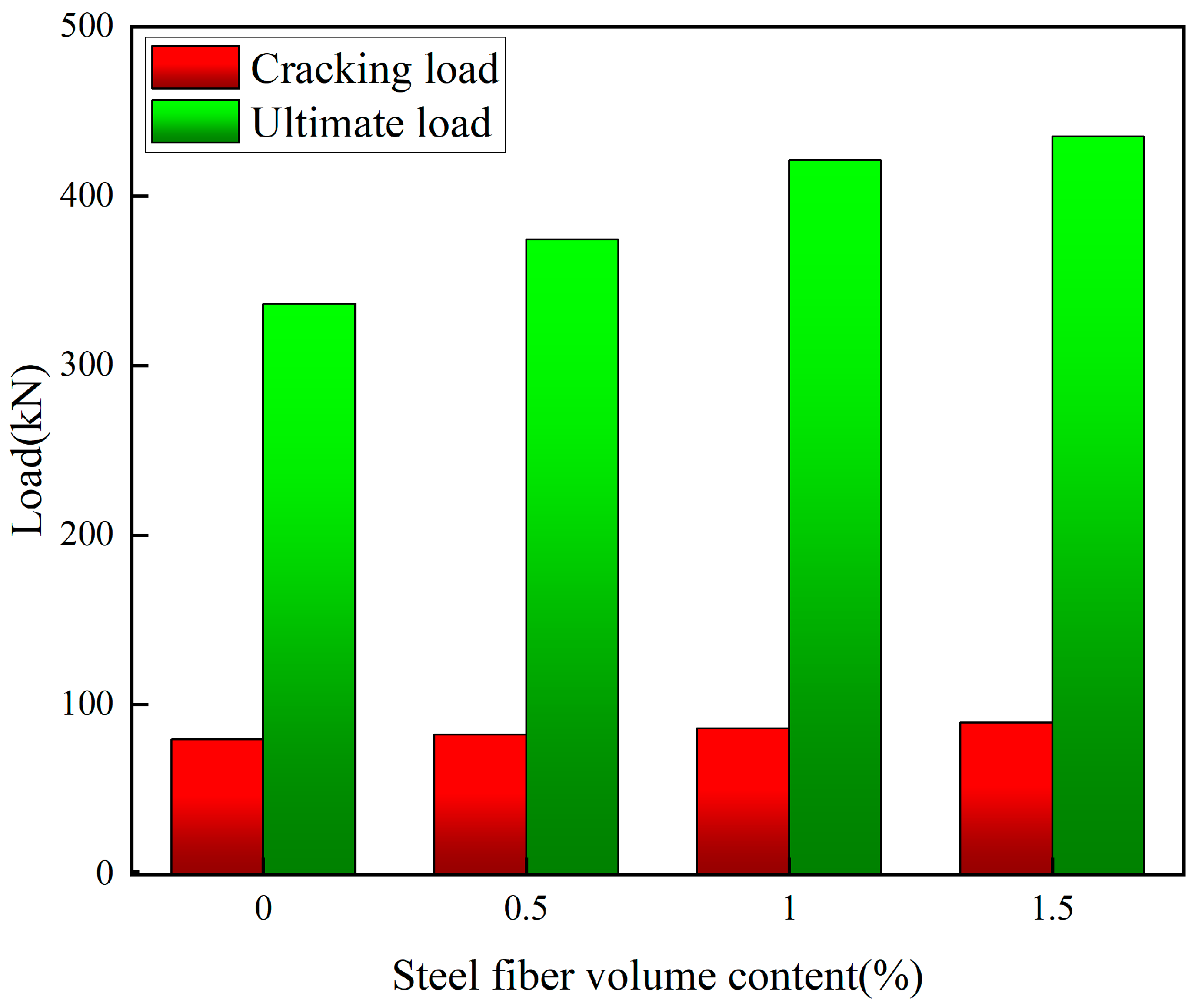
3.7. Effect of Volume Content of Steel Fibres on the Bearing Capacity of Specimens

The effect of different steel fibre volume content on the bearing capacity and lateral displacement of the specimens is shown in Figure 14. Under a large eccentric load, the bearing capacity of the columns rises, and the lateral displacement increases with an increase in steel fibre volume content. When the steel fibre admixture was increased from 0% to 0.5%, the cracking load of the specimens increased by 3.5% and the ultimate load by 7.1%. Similarly, when the volume content of the steel fibre was increased from 0.5% to 1%, the cracking load of the specimens was increased by 4.2%, and the ultimate load was increased by 9.3%. In contrast, when the steel fibre admixture was increased from 1% to 1.5%, the cracking load of the specimen was increased by only 2.1%, and the ultimate load was increased by only 5.4%. It can be clearly seen that when the amount of steel fibre doping exceeds 1%, there is a significant slowdown in the growth of the bearing capacity of the specimens. Considering the bearing performance and economical cost of the specimens, it is recommended that the volume content of steel fibres for SFCGC columns is about 1%.

4. Discussion

4.1. Calculation of Cracking Load Capacity

Since steel fibres play a role in structural cracking resistance, the effect of steel fibres must be considered when calculating cracking loads in eccentric compressed SFCGC columns. The measured values of tensile strength and modulus of elasticity of SFCGC were used to calculate the cracking load, as shown in Table 6. The cracking load equation for SFCGC columns under short-term loading can be obtained from references [42,46,47]. The calculated results are compared with the experimental results in Table 6.
N c r = γ m α c t f f t A 0 W 0 e 0 A 0 W 0
A 0 = b h + α E A s
W 0 = I 0 h y 0
y 0 = ( b h 2 / 2 + α E A s h 0 ) / ( b h + α E A s )
I 0 = b y 0 3 / 3 + b ( h y 0 ) 3 / 3 + α E A s ( h 0 y 0 ) 2
α E = E s / E c
ρ = A s / b h 0
where N c r is the concrete cracking load; γm is the plasticity coefficient of the resisting moment of the section, taken as 1.55; αct is the concrete tensile stress limiting factor, taken as 0.85; fft is the standard value of tensile strength of SFCGC, taking the actual measured value; A0 is the converted cross-sectional area of the member; e0 is eccentricity; W0 is the elastic resisting moment of the converted section to the edge of the concrete tensile zone; y0 is the distance from the axis of the centre of gravity of the converted section to the edge of the concrete compressive zone; I0 is the moment of inertia of the section to its centre of gravity axis; ρ is the reinforcement ratio of longitudinal tensile reinforcement; Es is the modulus of elasticity of longitudinal tensile reinforcement; Ec is the modulus of elasticity of concrete; As is the cross-sectional area of longitudinal tensile reinforcement.
The cracking load test values and the calculated values are shown in Table 6, their average ratio is 0.967, and the coefficient of variation is 0.0182; the predicted results are in good agreement with the test results.

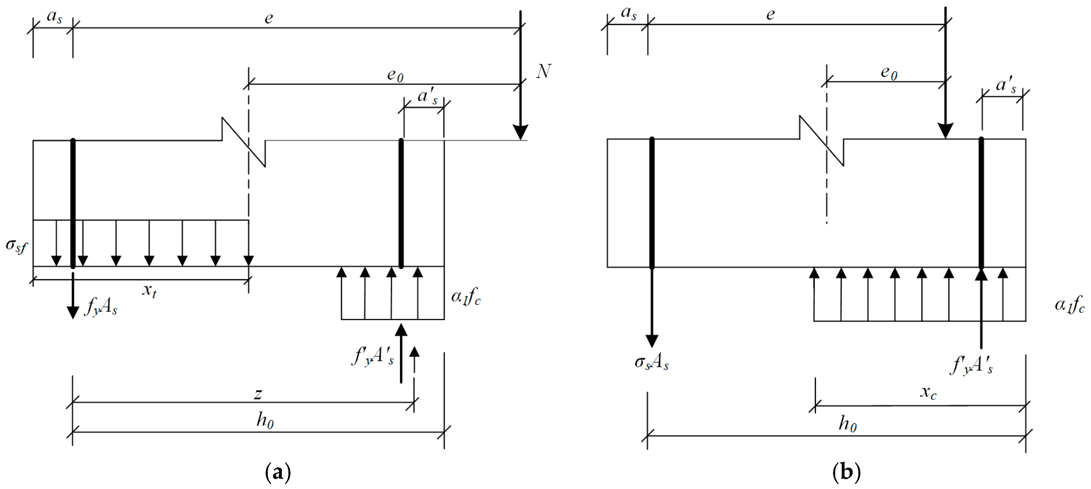
4.2. Calculation of the Ultimate Bearing Capacity

The load-bearing capacity calculations for the large and small eccentric pressed columns are shown in Figure 15. According to the force and moment balance conditions and coordination conditions given in the literature [42,46], the ultimate bearing capacity equations for columns are shown below, where Equations (9)–(12) are the equations for the calculation of the small eccentricity of the specimens. Equations (13)–(15) are the formulae for the calculation of the large eccentricity of the specimens.
N u = α 1 f c b x c + f y A s σ s A s
N u e = α f c b x c ( h 0 x c / 2 ) + f y A s ( h 0 a s )
e = η n s e 0 + h / 2 a s
σ s = E s ε c u ( h 0 / x c 1 )
N u = α 1 f c b x c f f t b x t + f y A s f y A s
N u e = α 1 f c b x c ( h 0 x c / 2 ) + f y A s ( h 0 a s ) f f t b x t ( x t / 2 a s )
x t = h x c / β
where Nu is the ultimate column load capacity; α, β is the concrete strength correlation coefficient, according to the specification GB50010-2010 [42] to take 0.91, 0.71; f y is the compression zone longitudinal reinforcement yield strength; fy is the yield strength of the longitudinal reinforcement in tension; A s is the cross-sectional area of the compressive reinforcement; σs is the strength of the longitudinal tensile reinforcement; As is the cross-sectional area of the longitudinal tensile reinforcement; xc is the height of the concrete compression zone; a s is the distance from the edge of the compressed zone to the point where the combined force of the compressed reinforcement acts; as is the distance from the edge of the tensile zone to the point where the combined force of the tensile reinforcement is applied; Es is the longitudinal tensile reinforcement modulus of elasticity; εcu is the ultimate compressive strain of coal gangue concrete, taken as 0.0033; h0 is the effective height of the section; fft is the tensile strength of the SFCGC; xt is the height of the concrete in tension; ηns is the second-order effect factor, which takes the value of one because second-order effects are not considered in this test.
Table 6 shows the experimental and calculated data with a mean ratio of 0.967 and a coefficient of variation of 0.0312, as expected.

4.3. Average Crack Spacing

Concerning the relevant provisions of the code CECS 2004 [46] and the relevant formulae of [48], the average crack spacing of SFCGC columns under eccentric compression was calculated using Equation (16); the average crack spacing of the specimens was calculated, and the test results are shown in Table 7.
l c r = k 1 c s + k 2 d e q ρ t e ( 1 + α t λ f )
ρ t e = A s / A t e
d e q = n d i 2 n i v i d i
where lcr is the average crack spacing of concrete; k1 is the coefficient related to the protective layer of SFCGC for longitudinal tensile reinforcement, and k2 is the coefficient related to the bonding performance between SFCGC and reinforcement; cs is the distance from the outer edge of the longitudinal tensile reinforcement to the edge of the tensile zone; deq is the equivalent diameter of the longitudinal tensile reinforcement (mm); ρte is the effective reinforcement ratio of longitudinal tensile reinforcement calculated according to the effective tensile concrete cross-sectional area, when ρte < 0.01, take ρte = 0.01; αt is the coefficient of bond enhancement due to the presence of steel fibres; Ate is the area of the effective tensioned concrete section; di, ni, vi denote the diameter, number of rods and relative bond characteristics of type i longitudinal tensile reinforcement, respectively, the relative bond characteristics of ribbed reinforcement are taken as 1.0.
By fitting the mean crack spacing in this study, the results of k1 = 1.86 and k2 = 0.10 can be obtained. Combined with the Chinese code [42,46], the average crack spacing equation can be obtained as follow:
l m = 1.86 c s + 0.1 d e q / ρ t e

4.4. Average Crack Width

The average crack width is equal to the difference between the average tensile elongation of the reinforcement and the concrete within the average crack spacing; due to the small tensile deformation of concrete, according to the literature [42,46,47], it is possible to introduce the coefficient of influence of tensile deformation of concrete αc and the strain unevenness coefficient of reinforcement between cracks ψ , from which we can obtain the Equation for calculating the average crack width of ordinary concrete:
w m = α c ψ σ s E s l m
ψ = 1.1 0.65 f f t ρ t e σ s
where wm is the average crack width of concrete; αc is the coefficient of influence of tensile deformation of concrete, which is taken as 0.77 according to the Chinese code [42,46]; ψ is the strain unevenness coefficient of longitudinal tensile reinforcement between cracks, which is taken as ψ = 0.2 when ψ < 0.2 and ψ =1 when ψ > 1; σs is the stress of longitudinal tensile reinforcement between cracks, which is calculated according to Equation (22).
In consideration of the effect of steel fibres on the mean crack width, the mean crack width equation was amended as follows:
w m = 0.77 ( 1 β w λ f ) ψ σ s E s l m
where βw is the coefficient of influence of steel fibres on the average crack spacing; λf indicates the characteristic value of steel fibre content (λf = ρflf/df); ρf indicates the volume rate of steel fibres; lf is the length of steel fibres; df is the diameter of steel fibres.
As shown in Figure 14, to obtain the equilibrium diagram of the internal forces between cracks, consider the influence of steel fibres in the tension zone, take the moment of the combined force point in the pressure zone to obtain the following formula, according to the equilibrium conditions to obtain the steel stress σs.
σ s = N ( e z ) σ s f b x t ( z x t / 2 + a s ) A s z
z = [ 0.87 0.12 ( h 0 e ) 2 ] h 0
e = η n s e 0 + h / 2 a s
σ s f = α t λ f f t
x t = 0.5 h
where e is the force loading point to the distance of the tension zone longitudinal reinforcement joint point; z is the distance of the tension zone longitudinal reinforcement joint point to the section concrete compression zone joint point; σsf is the crack between the steel fibre tensile stress; αt is the steel fibre on the coal gangue concrete tensile strength coefficient, according to the test to take 0.37; ft is the coal gangue concrete without considering the impact of steel fibre tensile strength, fft = ft(1 + αtλf); xt is the height of the effective tensile zone of the section affected by steel fibres.
By fitting the measured values of the average crack width to this experiment, we obtain βw = 0.186. The average crack width of SFCGC columns under eccentric compression is obtained according to Equation (21) as follows; the average crack width of the specimens is calculated and tested as shown in Table 8.
w m = 0.77 ( 1 0.186 λ f ) ψ σ s E s l m
From Table 8, the mean value of the ratio of the tested to the calculated mean crack width for the SFCGC columns is 1.035 with a coefficient of variation of 0.071, which indicates that the two values are close to each other. It is also clear from the test results that the average crack width decreases as the steel fibre dose increases. It further shows that the average crack width of SFCGC columns proposed in this test is in good agreement with the test results and has good calculation accuracy.

4.5. Maximum Crack Width

The maximum crack width wmax of the specimens under short-term loading can be obtained by multiplying the average crack width wm by the enlargement factor αs. Owing to the few specimens in this test, the average crack width expansion factor was taken as 1.66 according to the specification [46,48]. The formula is as follows:
w max = 1.66 w m
According to Table 8, the mean of the ratio between the tested and calculated values of the maximum crack width for the SFCGC columns is 1.047, and the coefficient of variation is 0.053, which gives a good agreement, indicating that the formula for calculating the maximum crack width for the NAC columns is applicable to the SFCGC columns.

5. Conclusions

Based on the experimental and theoretical study of the behaviour of SFCGC columns under eccentric compression loading, the following conclusions can be drawn:
(1)
The whole process of loading the SFCGC column to the ultimate state is in accordance with the plane cross-section assumption. During the loading process, the lateral displacement curve of the SFCGC column is approximately sinusoidal and symmetrically distributed in the middle. Under the same eccentricity, the coal gangue replacement rate of the SFCGC columns has little effect on the lateral displacement corresponding to the ultimate load. The final damage mode of the SFCGC columns resembled that of the NAC columns, and their bearing capacity was greatly influenced by eccentricity.
(2)
The increased crack resistance of SFCGC columns is directly associated with their increased tensile strength. By means of applying the corresponding tensile strength (fft) of SFCGC, the formula for NAC columns can be used for SFCGC columns.
(3)
The cracking spacing decreased with an increase in steel fibres. The reduction of longitudinal reinforcement stress contributed to the decline of crack width. On the basis of the regression analysis of experiment results, the equations for computing the average crack spacing and average crack width of SFCGC columns were presented. For these results, there is excellent consistency with the experimental results.
(4)
A salutary effect of steel fibres in improving the load-bearing capacity of SFCGC columns is shown. Considering the beneficial contribution of steel fibres in the tension zone, equations are presented to predict the axial load under load-bearing conditions. Acceptable prediction accuracy indicates the suitability of SFCGC for its structural applications.
(5)
The increase in the coal gangue replacement rate will lead to a certain degree of reduction in the bearing capacity of the specimens. Compared with the replacement rate of the 30% SFCGC column, when the gangue replacement rate is at 50% and 70%, the reduction of the ultimate bearing capacity of the specimens increases significantly. It is recommended that the coal gangue replacement rate for SFCGC columns is about 30%.
(6)
Steel fibres can effectively compensate for the negative impact of gangue on the bearing capacity of SFCGC columns. As the volume content of steel fibres increases from 0% to 0.5% and 1%, the ultimate load capacity of the SFCGC increases by 7.1% and 9.3%, respectively. When the steel fibre content exceeds 1% by volume to 1.5%, the increase in ultimate load capacity of the SFCGC column begins to slow down and only increases by 5.4%. In view of the load-bearing performance and cost-effectiveness of the specimens, it is suggested that the volume content of steel fibres for SFCGC columns be about 1%.

Author Contributions

Conceptualization, B.C.; methodology, B.C.; test, B.B. and W.D.; validation, B.B. and S.W.; investigation, L.W. and S.W.; resources, B.C.; data curation, W.D. and L.W.; writing—original draft preparation, B.B.; writing—review and editing, B.B.; visualization, B.C.; supervision, B.C.; project administration, B.C.; funding acquisition. All authors have read and agreed to the published version of the manuscript.

Funding

This research was funded by Scientific research projects of the education department of Jilin Province, grant number JJKH20210279KJ, JJKH20200279KJ; China Scholarship Council, grant number 201805975002; and Jilin Provincial Science and Technology Development Plan Project, grant number 20220203082SF. The authors wish to acknowledge the sponsors. However, any opinions, findings, conclusions and recommendations presented in this paper are those of the authors and do not necessarily reflect the views of the sponsors.

Institutional Review Board Statement

Not applicable.

Informed Consent Statement

Not applicable.

Data Availability Statement

The data used to support the findings of this study are available from the authors upon request.

Conflicts of Interest

The authors declare no conflict of interest.

References

  1. Chang, J.; Du, G.; Du, J.; Shi, X. Current Situation of the Comprehensive Utilization of Coal Gangue in China and the Related Problems and Recommendations. China Environ. Prot. Ind. 2022, 8, 13. [Google Scholar]
  2. Wang, B.; Ma, Y.N.; Lee, X.Q.; Wu, P.; Liu, F.; Zhang, X.; Li, L.; Chen, M. Environmental-friendly coal gangue-biochar composites reclaiming phosphate from water as a slow-release fertilizer. Sci. Total Environ. 2020, 758, 143664. [Google Scholar] [CrossRef] [PubMed]
  3. Gong, C.; Yan, J.; Liu, J.; Yu, H. Biology Migration and Distribution Characteristics of Trace Elements in Reconstructed Soil with Coal Gangue Filling. Agric. Sci. Technol. 2016, 17, 2167–2170. [Google Scholar]
  4. Pone, J.D.N.; Hein, K.A.A.; Stracher, G.B.; Annegarn, H.J.; Finkleman, R.B.; Blake, D.R.; Mccormack, J.K.; Schroeder, P. The spontaneous combustion of coal and its by-products in the Witbank and Sasolburg coalfields of South Africa. Int. J. Coal Geol. 2007, 72, 124–140. [Google Scholar] [CrossRef]
  5. Querol, X.; Zhuang, X.; Font, O.; Izquierdo, M.; Alastuey, A.; Castro, I.; Drooge, B.L.V.; Moreno, T.; Grimalt, J.O.; Elvira, J. Influence of soil cover on reducing the environmental impact of spontaneous coal combustion in coal waste gobs: Are view and new experimental data. Int. J. Coal Geol. 2011, 85, 2–22. [Google Scholar] [CrossRef]
  6. Laurance, W.F.; Peletierjellema, A.; Geenen, B.; Koster, H.; Verweij, P.A.; Dijck, P.V.; Lovejoy, T.E.; Schleicher, J.; Kuijk, M.V. Reducing the global environmental impacts of rapid infrastructure expansion. Curr. Biol. 2015, 25, 259–262. [Google Scholar] [CrossRef]
  7. Monteiro, P.J.M.; Miller, S.A.; Horvath, A. Towards sustainable concrete. Nat. Mater. 2017, 16, 698–699. [Google Scholar] [CrossRef]
  8. Al-Oraimi, S.K.; Taha, R.; Hassan, H.F. The effect of the mineralogy of coarse aggregate on the mechanical properties of high-strength concrete. Construct. Build. Mater. 2006, 20, 499–503. [Google Scholar] [CrossRef]
  9. Wu, J.; Bai, G.L.; Wang, P.; Liu, Y. Mechanical properties of a new type of block made from shale and coal gangue. Constr. Build. Mater. 2018, 190, 796–804. [Google Scholar] [CrossRef]
  10. Qin, J.G.; Zhao, R.D.; Chen, T.J.; Zi, Z.Y.; Wu, J.H. Co-combustion of municipal solid waste and coal gangue in a circulating fluidized bed combustor. Int. J. Coal. Sci. Technol. 2019, 6, 218–224. [Google Scholar] [CrossRef]
  11. Guo, Y.; Yan, K.; Cui, L.; Cheng, F. Improved extraction of alumina from coal gangue by surface mechanically grinding modification. Powder Technol. 2016, 302, 33–41. [Google Scholar] [CrossRef]
  12. Li, Y.; Yao, Y.; Liu, X.M.; Sun, H.H.; Ni, W. Improvement on pozzolanic reactivity of coal gangue by integrated thermal and chemical activation. Fuel 2013, 109, 527–533. [Google Scholar] [CrossRef]
  13. Sun, Y.X.; Li, X.D. Development and design of coal gangue concrete filling material. Adv. Mater. Res. 2011, 295, 1198–1201. [Google Scholar] [CrossRef]
  14. Wang, Z.; Zhao, N. Influence of coal gangue aggregate grading on strength properties of concrete. Wuhan Univ. J. Nat. Sci. 2015, 20, 66–72. [Google Scholar] [CrossRef]
  15. Ma, H.Q.; Zhu, H.G.; Wu, C.; Chen, H.Y.; Sun, J.W.; Liu, J.Y. Study on compressive strength and durability of alkali-activated coal gangue-slag concrete and its mechanism. Powder Technol. 2020, 368, 112–124. [Google Scholar] [CrossRef]
  16. Li, X.; Pan, M.; Tao, M.; Liu, W.; Gao, Z.; Ma, C. Preparation of high closed porosity foamed ceramics from coal gangue waste for thermal insulation applications. Ceram. Int. 2022, 48, 37055–37063. [Google Scholar] [CrossRef]
  17. Qiu, J.; Zhou, Y.; Vatin, N.I.; Guan, X.; Sultanov, S.; Khemarak, K. Damage constitutive model of coal gangue concrete under freeze-thaw cycles. Constr. Build. Mater. 2020, 264, 120720. [Google Scholar] [CrossRef]
  18. Xiao, M.; Ju, F.; He, Z.Q. Research on shotcrete in mine using non-activated waste coal gangue aggregate. J. Clean. Prod. 2020, 259, 120810. [Google Scholar] [CrossRef]
  19. Liu, H.; Xu, Q.; Wang, Q.; Zhang, Y. Prediction of the elastic modulus of concrete with spontaneous-combustion and rock coal gangue aggregates. Structures 2020, 28, 774–785. [Google Scholar] [CrossRef]
  20. Ma, H.Q.; Yi, C.; Zhu, H.G.; Dong, Z.C.; Chen, H.Y.; Wang, J.X.; Li, D.Y. Compressive strength and durability of coal gangue aggregate concrete. Mater. Rev. 2018, 32, 2390–2395. [Google Scholar]
  21. Gao, S.; Zhao, G.; Guo, L.; Zhou, L.; Yuan, K. Utilization of coal gangue as coarse aggregates in structural concrete. Constr. Build. Mater. 2021, 268, 121212. [Google Scholar] [CrossRef]
  22. Zhu, H.; Yang, S.; Li, W.; Li, Z.; Fan, J.; Shen, Z. Study of mechanical properties and durability of alkali-activated coal gangue-slag concrete. Materials 2020, 13, 5576. [Google Scholar] [CrossRef] [PubMed]
  23. Chen, B. Strength of coal gangue Concrete. Ind. Constr. 1994, 7, 29–32. [Google Scholar]
  24. Guan, X.; Qiu, J.; Song, H.; Qin, Q.; Zhang, C. Stress–strain behaviour and acoustic emission characteristic of gangue concrete under axial compression in frost environment. Constr. Build. 2019, 220, 476–488. [Google Scholar]
  25. Moghadam, M.J.; Ajalloeian, R.; Hajiannia, A. Preparation and application of alkaliactivated materials based on waste glass and coal gangue: A review. Constr. Build. Mater. 2019, 221, 84–98. [Google Scholar] [CrossRef]
  26. Katzer, J.; Domski, J. Quality and mechanical properties of engineered steel fibres used as reinforcement for concrete. Constr. Build. Mater. 2012, 34, 243–248. [Google Scholar] [CrossRef]
  27. Atiş, C.D.; Karahan, O. Properties of steel fibre reinforced fly ash concrete. Constr. Build. Mater. 2009, 23, 392–399. [Google Scholar] [CrossRef]
  28. Wang, L.; Shen, N.; Zhang, M.; Fu, F.; Qian, K. Bond performance of Steel-CFRP bar reinforced coral concrete beams. Constr. Build. Mater. 2020, 245, 118456. [Google Scholar] [CrossRef]
  29. Li, L.; Qin, H.G. Study of interface bonding performance of steel fibres within cement mortar. J. Luoyang Univ. 2002, 17, 82–85. [Google Scholar]
  30. Cheng, J.; Liu, J.P.; Zhang, L.H. Testing and mechanism analysis of the fibre-matrix bonding properties of ultrahigh performance concrete. China Concr. Cem. Prod. 2016, 5, 62–66. [Google Scholar]
  31. Campione, G.; La Mendola, L. Behavior in compression of lightweight fibre reinforced concrete confined with transverse steel reinforcement. Cem. Concr. Compos. 2004, 26, 645–656. [Google Scholar] [CrossRef]
  32. Sharma, U.K.; Sheikh, S.A.; Bhargava, P. Tie-confined fibre-reinforced high-strength concrete short columns. Mag. Concr. Res. 2007, 59, 757–769. [Google Scholar] [CrossRef]
  33. Li, Y.J.; Geng, X.; Zhang, X.; Yan, X. Experimental study on the durability of the concrete with coal gangue aggregate. J. China Coal Soc. 2013, 38, 1215–1219. [Google Scholar]
  34. Zhang, J.X.; Chen, W.L.; Jin, S.S.; Chen, C.Z.; Yang, R.J. Investigation on durability of coal gangue aggregate concrete. J. Beijing Univ. Technol. 2011, 37, 115–125. [Google Scholar]
  35. Liu, H.; Bai, G.; Gu, Y.; Yan, F. The influence of coal gangue coarse aggregate on the mechanical properties of concrete columns. Case Stud. Constr. Mater. 2022, 17, e01315. [Google Scholar] [CrossRef]
  36. Luo, D.M.; Wang, Y.; Zhang, S.H.; Niu, D.T.; Song, Z.P. Frost resistance of coal gangue aggregate concrete modified by steel fibre and slag powder. Appl. Sci. 2020, 10, 3229. [Google Scholar] [CrossRef]
  37. Wang, Y.; Qiu, J.; Deng, W.; Xing, J.; Liang, J. Factors affecting brittleness behavior of coal-gangue ceramsite lightweight aggregate concrete. Front. Mater. 2020, 7, 554718. [Google Scholar] [CrossRef]
  38. Le, D.B.; Tran, S.D.; Dao, V.T.; Torero, J. Deformation capturing of concrete structures at elevated temperatures. Procedia Eng. 2017, 210, 613–621. [Google Scholar]
  39. Yu, K.; Yu, J.; Lu, Z.; Chen, Q. Determination of the softening curve and fracture toughness of high-strength concrete exposed to high temperature. Eng. Fract. Mech. 2015, 149, 156–169. [Google Scholar] [CrossRef]
  40. JGJ 51-2002; Technical Specification for Light Aggregate Concrete. China Architecture & Building Press: Beijing, China, 2002.
  41. GB 175-2020; Common Portland Cement. China Standardization Administration Press: Beijing, China, 2020.
  42. GB 50010-2010; Ministry of Housing and Urban-Rural Construction of the People’s Republic of China (MHURC-PRC). China Building Industry Press: Beijing, China, 2010.
  43. Lin, G.; Zeng, J.J.; Teng, J.G.; Li, L.J. Behavior of large-scale FRP-confined rectangular RC columns under eccentric compression. Eng. Struct. 2022, 216, 110759. [Google Scholar] [CrossRef]
  44. Hadi, M.N. Behaviour of eccentric loading of FRP confined fibre steel reinforced concrete columns. Constr. Build. Mater. 2009, 23, 1102–1108. [Google Scholar] [CrossRef]
  45. Qing, K.; Han, F.; Xing, L.; Wang, X. Experimental study on the flexural performance of BFRP reinforced steel fibre recycled concrete beams. Fiber Reinf. Plast./Compos. 2019, 11, 5. [Google Scholar]
  46. CECS 38:2004; China Association for Engineering Construction Standardization. China Planning Press: Beijing, China, 2004.
  47. Li, C.Y.; Ding, X.X.; Zhao, S.B.; Zhang, X.Y.; Li, X.K. Cracking resistance of reinforced SFRFLC superposed beams with partial ordinary concrete in compression zone. Open Civ. Eng. J. 2016, 10, 727–737. [Google Scholar] [CrossRef]
  48. Zhao, S.B. Design Principles of Concrete Structures, 2nd ed.; Tongji University Press: Beijing, China, 2013. [Google Scholar]
Figure 1. Materials.
Buildings 13 01290 g001
Figure 2. Preparation of specimen: (a) Design of reinforcement (units: mm), (b) Steel bar cage.
Buildings 13 01290 g002
Figure 3. The specimen fabrication process.
Buildings 13 01290 g003
Figure 4. Test design: (a) measurement point layout, (b) DIC and testing machine.
Buildings 13 01290 g004
Figure 5. Specimen failure modes: (a) S-0-1, (b) S-30-1, (c) S-50-1, (d) L-0-1, (e) L-30-1, (f) L-50-1, (g) L-70-1, (h) L-50-0, (i) L-50-0.5, (j) L-50-1.5.
Buildings 13 01290 g005aBuildings 13 01290 g005b
Figure 6. Nephogram of the strain process: (a) L-0-1 under 0.2 Nu, (b) L-0-1 under 0.4 Nu, (c) L-0-1 under 0.6 Nu, (d) L-0-1 under 0.8 Nu, (e) L-30-1 under 0.2 Nu, (f) L-30-1 under 0.4 Nu, (g) L-30-1 under 0.6 Nu, (h) L-30-1 under 0.8 Nu, (i) L-50-1 under 0.2 Nu, (j) L-50-1 under 0.4 Nu, (k) L-50-1 under 0.6 Nu, (l) L-50-1 under 0.8 Nu, (m) L-70-1 under 0.2 Nu, (n) L-70-1 under 0.4 Nu, (o) L-70-1 under 0.6 Nu, (p) L-70-1 under 0.8 Nu.
Buildings 13 01290 g006aBuildings 13 01290 g006bBuildings 13 01290 g006c
Figure 7. Strain distribution in mid-span sections of concrete: (a) S-0-1, (b) S-30-1, (c) S-50-1, (d) L-0-1, (e) L-30-1, (f) L-50-1, (g) L-70-1, (h) L-50-0, (i) L-50-0.5, (j) L-50-1.5.
Buildings 13 01290 g007aBuildings 13 01290 g007b
Figure 8. The load-strain curve of concrete.
Buildings 13 01290 g008
Figure 9. The load-reinforced steel strain curve.
Buildings 13 01290 g009
Figure 10. Axial displacement versus load curves for specimens.
Buildings 13 01290 g010
Figure 11. Lateral deflection curves: (a) S-0-1, (b) S-30-1, (c) S-50-1, (d) L-0-1, (e) L-30-1, (f) L-50-1, (g) L-70-1, (h) L-50-0, (i) L-50-0.5, (j) L-50-1.5.
Buildings 13 01290 g011aBuildings 13 01290 g011b
Figure 12. Load–lateral displacement curve.
Buildings 13 01290 g012
Figure 13. Effect of coal gangue replacement rate on column bearing capacity: (a) small eccentricity, (b) large eccentricity.
Buildings 13 01290 g013
Figure 14. Effect of steel fibre volume content on column bearing capacity.
Buildings 13 01290 g014
Figure 15. Equivalent force distribution in the positive section of the eccentrically pressed column: (a) Large eccentricity, (b) Small eccentricity.
Buildings 13 01290 g015
Table 1. Physical properties of steel fibres.
Steel FibreLength (mm)Width (mm)Thickness (mm)Equivalent Diameter (mm)Aspect RatioDensity (g/cm3)
CSF3810.35–0.50.76507.8
Table 2. Chemical composition of cement.
Chemical CompositionSiO2Al2O3MgONa2OCaOFe2O3f-CaOK2O
Content (%)22.44.63.000.464.23.51.30.6
Table 3. Physical properties of cement.
CementConservation Times (Day)Rupture Strength (Mpa)Compressive Strength (Mpa)
P-O42.535.58.4
288.451.6
Table 4. Chemical composition of coal gangue.
Chemical CompositionSiO2Al2O3FeOMgOBaONa2OTiO2Fe2O3P2O5MnOK2O
Content (%)36.8336.835.835.005.662.831.773.510.390.151.65
Table 5. Specimen detail.
SpecimensVc (%)Vf (%)e0 (mm)CWSCA (kg/m3)Wr
(kg/m3)(kg/m3)(kg/m3)NCG(kg/m3)
S-0-10150503.7201.56231155.505.04
S-30-130150503.7201.56231048.83605.04
S-50-150150503.7201.5623749.6598.55.04
L-0-101100503.7201.56231155.505.04
L-30-1301100503.7201.56231048.8598.55.04
L-50-1501100503.7201.5623749.6598.55.04
L-70-1701100503.7201.5623450.38405.04
L-50-0500100503.7201.5623749.6598.55.04
L-50-0.5500.5100503.7201.5623749.6598.55.04
L-50-1.5501.5100503.7201.5623749.6598.55.04
Note: C = cement; W = water; S = sand; CA = coarse aggregate; N = natural; CG = coal gangue; Wr = water reducer; Vc = coal gangue replacement rate; Vf = steel fibre volume content.
Table 6. Load-bearing capacity and ductility of specimens.
Specimensfcu (Mpa)fft (Mpa)Ncr (kN)Nu (kN)
NexpNtheoNexp/NtheoNexpNtheoNexp/Ntheo
S-0-139.963.63452.6475.420.952731722.131.012
S-30-136.363.55450.5457.710.984665.2677.630.982
S-50-133.093.27447.9441.251.015605.3636.890.951
L-0-139.963.6390.494.030.961553506.131.093
L-30-136.363.558989.890.991503.2461.881.089
L-50-133.093.2782.585.980.959457.9421.411.087
L-70-130.443.1280.382.710.972421.3388.531.084
L-50-027.872.977579.450.944385.9356.591.082
L-50-0.530.123.1178.382.290.951416.7384.411.084
L-50-1.536.073.3682.8387.710.944480.8458.241.047
Table 7. Average crack spacing of specimens.
SpecimensLm
TestedCalculatedTested/Calculated
S-0-161.361.261.001
S-30-163.061.261.028
S-50-160.961.260.994
L-0-162.361.261.017
L-30-161.261.260.998
L-50-160.161.261.038
L-70-163.661.261.012
L-50-066.866.770.996
L-50-0.564.363.841.007
L-50-1.560.758.951.029
Table 8. Crack width of specimens.
SpecimensN/Nuwmwmax
TestedCalculatedTested/
Calculated
TestedCalculatedTested/
Calculated
S-0-170%0.0160.01720.9300.0300.02861.050
80%0.0210.02220.9460.0380.03681.032
90%0.0270.02720.9940.0460.04511.020
S-30-170%0.0140.01590.8780.0280.02651.057
80%0.0210.02061.0180.0350.03421.022
90%0.0260.02531.0280.0410.04200.976
S-50-170%0.0150.01481.0110.0240.02460.975
80%0.0210.01921.0920.0340.03191.065
90%0.0240.02361.0160.0420.03921.071
L-0-130%0.0110.00951.1580.0160.01571.014
50%0.0300.02761.0870.0500.04581.091
70%0.0490.04571.0720.0770.07591.015
L-30-130%0.0090.00801.1220.0140.01331.051
50%0.0240.02450.9780.0450.04071.104
70%0.0410.04100.9990.0730.06821.071
L-50-130%0.0080.00671.1950.0130.01111.169
50%0.0220.02181.0110.0400.03611.107
70%0.0370.03681.0040.0640.06121.047
L-70-130%0.0060.00561.0630.0100.00941.067
50%0.0210.01951.0750.0360.03241.110
70%0.0360.03341.0770.0580.05551.045
L-50-030%0.0050.00570.8690.0110.00961.152
50%0.0220.02051.0720.0330.03410.969
70%0.0340.03530.9640.0600.05861.024
L-50-0.530%0.0070.00641.0930.0120.01061.129
50%0.0220.02191.0050.0380.03631.046
70%0.0410.03741.0970.0610.06210.983
L-50-1.530%0.0080.00721.1080.0110.01200.918
50%0.0230.02191.0520.0370.03631.019
70%0.0380.03651.0410.0610.06061.007
Disclaimer/Publisher’s Note: The statements, opinions and data contained in all publications are solely those of the individual author(s) and contributor(s) and not of MDPI and/or the editor(s). MDPI and/or the editor(s) disclaim responsibility for any injury to people or property resulting from any ideas, methods, instructions or products referred to in the content.

