Article

Development of a Water Supplement System for a Tuned Liquid Damper under Excitation

1
China Academy of Building Research, No. 30 North Third Ring Road East, Beijing 100029, China
2
National Engineering Research Center of Building Technology, No. 30 North Third Ring Road East, Beijing 100029, China
*
Author to whom correspondence should be addressed.
Buildings 2023, 13(5), 1115; https://doi.org/10.3390/buildings13051115
Submission received: 26 February 2023 / Revised: 9 April 2023 / Accepted: 20 April 2023 / Published: 22 April 2023
(This article belongs to the Special Issue Structural Vibration Control Research)

Abstract

:
Integrating existing liquid storage and supply tanks in buildings with tuned liquid dampers (TLDs) are significant for reducing the effective cost of TLDs. However, existing water supplement devices for fire-suppression liquid tanks may overfill with water, which leads to TLD mistuning. To overcome this problem, a passive liquid control system named TLD with a stable replenishment sub-tank system (TLD-SRS) is proposed. The system, which consists of an additional sub-tank connected to the main tank and a floating ball, replenishes liquid in the TLD automatically. The system can avoid vibration interference and maintain the normal operation of the passive replenishment system under usual wind loads. According to the studies of tuned liquid column dampers (TLCD), the proposed TLD with a stable replenishment sub-tank system (TLD-SRS) uses simple devices to ensure that the liquid level in the TLD is steady at the target liquid level with a floating ball. The TLD-SRS is verified on a large-scale TLD shaking table experiment. The overshoot, which is the percentage of liquid that exceeds the target volume of TLD is calculated during sloshing with wind loads. Compared with TLD installed with a regular liquid replenishment device, the proposed TLD-SRS significantly reduces the overshoot of liquid and acceleration on the roof of the building.

1. Introduction

To ensure the safety and comfort of civil engineering structures under loads such as wind, earthquakes and wave loads, the vibrations of the structures need to be controlled. Aerodynamic modification techniques are one kind of vibration control measure, which change the vortex shedding phenomenon of the building, including via corner cutting, rounding, chamfering, tapering, set-back and twisting [1]. Energy dissipation techniques are another kind of measure, including active, semi-active and active control techniques.
Different energy dissipation devices are installed in the utilization of passive control techniques [2]. Passive damping techniques include tuned mass dampers (TMD) [3], tuned liquid dampers (TLD), viscous dampers [4], visco-elastic dampers [5], inertial dampers [6,7] and other dampers [8]. Usually, tuned mass dampers and tuned liquid dampers are set at the top of the building to increase the damping effect in the resonance frequency range. The damping efficiency of the tuned damper is high, and only a small mass and damping force can significantly reduce the response of the structure [9].
Commonly used TLDs include rectangular tank tuned liquid dampers [10], ring-shaped tank tuned liquid dampers [11], tuned liquid column dampers (TLCD) [12], tuned liquid column absorbers (TLCA) [13] and asymmetric liquid column dampers [14]. The rectangular tank TLD is the most commonly used type of damper [15]. Compared with a deep-liquid tank, a shallow-liquid tank has higher damping efficiency [16]. A TLD can be equivalent to a series of parallel TMDs [17]. Flow-damping devices such as screens, nets, poles, baffles and floating objects can be installed in the tank to improve the damping ratio of TLDs [18].
The key to the design of tuned dampers is to confirm the optimal frequency and damping ratio. H2 and H∞ optimization are used for narrowband excitation and broadband excitation [19]. The optimal period and damping ratio of a tuned damper are obtained via an optimization algorithm [20]. When a TLD or TMD is mistuned [21], the damping effect of the damper decreases significantly. The sloshing frequency of TLDs is related to the liquid level and tank width. The TLD is mistuned when decreasing or overfilling the liquid. Tait [22] considered the reduction in the damping efficiency of frequency deviation in different excitation amplitudes. Roy [23] studied the influence of the tuning ratio on the damping efficiency under small vibrations. Robustness was used to study the influence of mistuned TLDs caused by liquid level deviations on the damping efficiency of a high girder liquid tank [21].
Integrating existing liquid storage and supply systems in buildings with TLDs to reduce the effective cost of TLDs is a significant topic [24]. For example, various liquid tanks on top of buildings and wind turbines, storage tanks on offshore or ground-supported platforms and elevated reservoirs are very common facilities that can be designed with the addition of passive damping functions. However, the main reasons for not considering these tanks as TLDs are as follows: (1) there may be multiple connected systems for the tanks, and unpredictable sloshing may influence other tanks during shaking (e.g., fire suppression water tanks); and (2) there may be large evaporative volumes in these tanks (when the tanks are open), or there may be inlet and outlet problems (overfilling problems). These increase the difficulties of controlling liquid levels.
During preliminary building design, it is economical to design a fire suppression or water supply tank as a TLD in which the liquid is steady and only used in emergency situations (such as fires or special water shortages). However, the liquid supplement of the tank for emergency is usually controlled by a floating ball to ensure that the liquid level is not lower than the minimum target liquid level and that the over supplementation of the liquid in the tank is not really concerned. To ensure the damping efficiency of TLDs, it is necessary to ensure that the liquid level in the TLD does not deviate too much from the target liquid level.
The liquid level control has applications in many aspects [25,26]. An electrical level sensor [27] circuit was designed to control the replenishment of a fire suppression liquid tank [28]. A seven-level liquid level control system using ultrasonic sensors was also used to control the liquid level more precisely [29,30]. In process industries, the control of liquid levels in storage tanks is a common and important control problem. A PID controller was used to control the liquid level in the tank with simultaneous liquid inlets and outlets [31]. More new PID controllers have been proposed for better robustness and smaller overshoot [32,33,34,35]. The overshoot and undershoot of the liquid in the tank means the percentage of the liquid that exceeds the target amount or that is below the target amount of the liquid. For the damping efficiency of TLDs, the overshoot of the tank with TLDs should be reduced as much as possible.
Effective TLDs are usually set at places with large structural vibrations, and their fundamental frequencies are close to that of the main structure. TLDs are easily excited to slosh when the controlled structure has a small vibration. The nonlinear problems of liquid sloshing, such as the coupling of sloshing modes [36,37,38], rotary sloshing, chaotic sloshing [39], sloshing–slamming [40], surface tension [37] and the wave breaking effect, make it difficult to identify the liquid surface in the sloshing and the real liquid volume in the tank. According to Love’s study [36], the predicted peak TLD wave heights show a maximum error of 20% from the experimental results. Incorrectly starting the liquid supplement device leads to the liquid depth deviating from the target liquid depth, which reduces the damping efficiency of TLDs.
The PID controllers mentioned above are usually complex and used in tanks without sloshing. More details of the sloshing states should be considered if we adopt these controllers. Some liquid replenishment systems are feasible, including additional long-term liquid level monitoring systems with more liquid sensors and liquid depth prediction algorithms, artificial patrols and strictly controlling the timing of liquid replenishment to maintain low liquid sloshing. However, these active or semi-active liquid replenishment methods increase the complexity of the liquid replenishment system. To decrease the cost of the water supplement system and guarantee that the system is simple and reliable, it is also better to use passive liquid level control devices rather than active liquid level controllers. Tanmoy [41] proposed a kind of passive liquid level control device to improve the readily available liquid storage tanks as TLDs and to overcome fluctuations in the liquid levels of the tanks. A floating base was designed to separate the water in the tanks and keep the water level above the floating base at an optimal level, acting as a regular TLD with an auto adjusted water level.
In this paper, another passive liquid level control system is proposed that can improve the fire suppression or water supply tank as a TLD. The TLD with a stable replenishment sub-tank system (TLD-SRS) consists of a regular TLD, a replenishment sub-tank and a pipe connecting them. A passive liquid replenishment system TLD-SRS is proposed to maintain the stable liquid level of the TLD. The TLD-SRS system is designed based on the studies of TLDs, TLCDs and TLCAs. It uses simple devices, such as a floating ball for water supplement control without complex measurements, controllers, or mechanical devices. With an additional sub-tank whose sloshing frequency differs from that of the main tank, the overshoot of the TLD is greatly reduced. The main contents of this study are as follows:
(1)
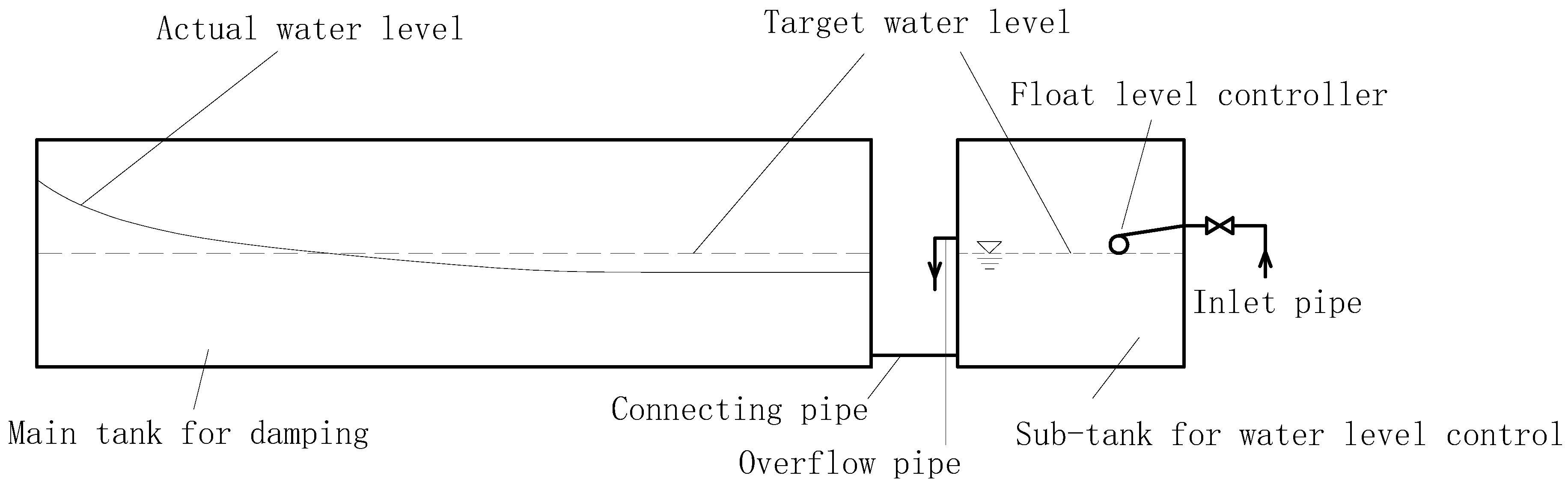
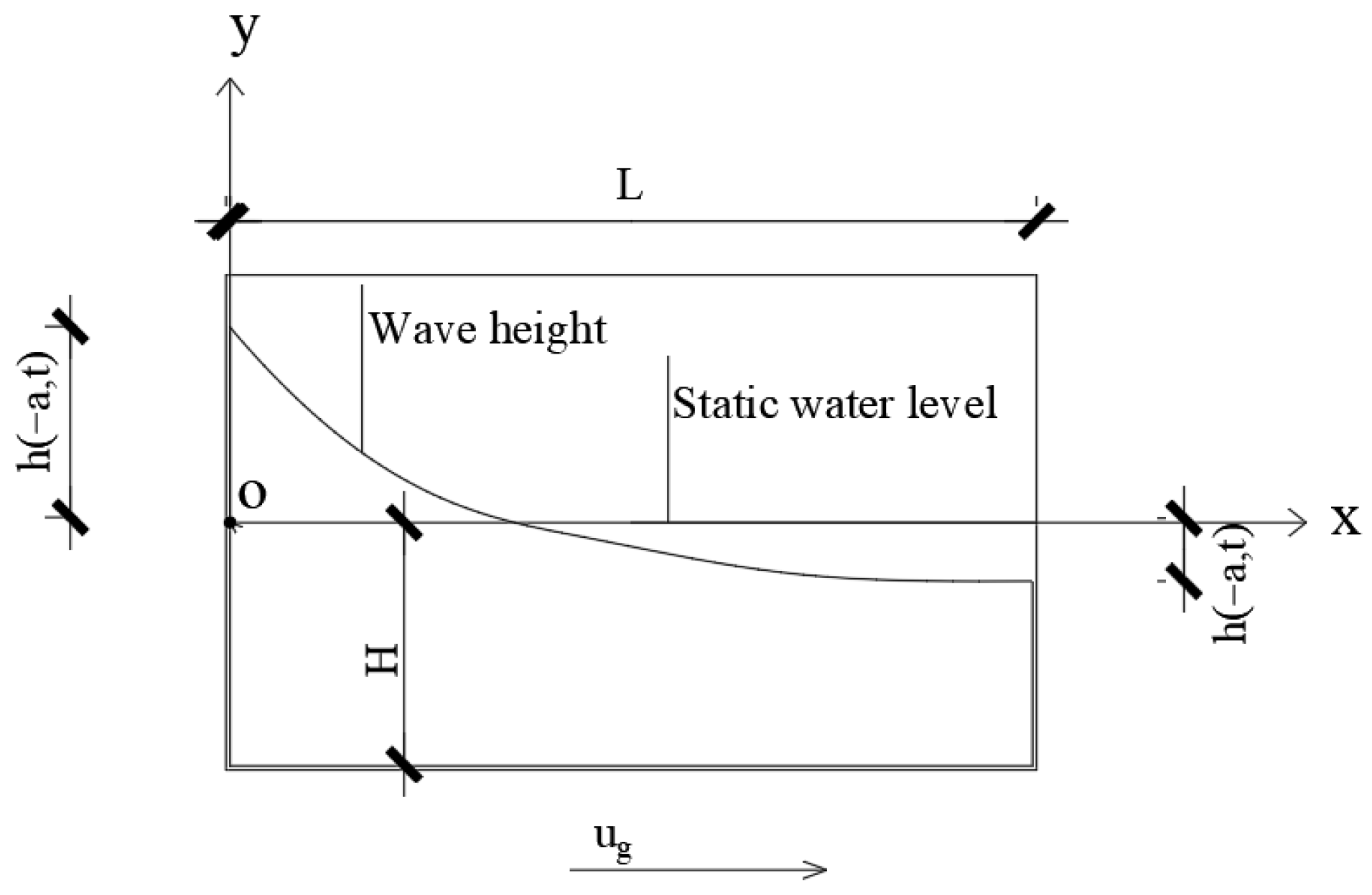
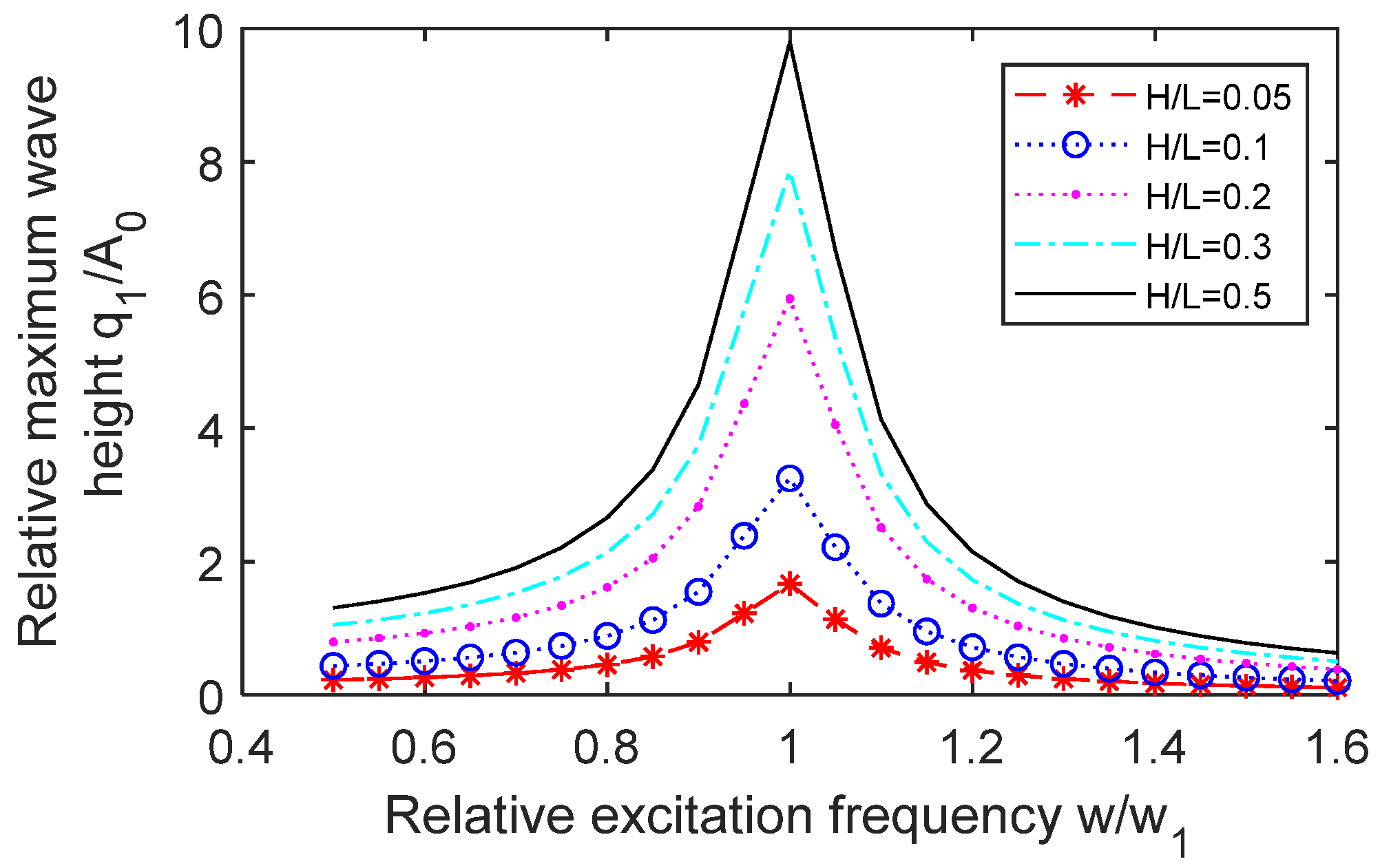
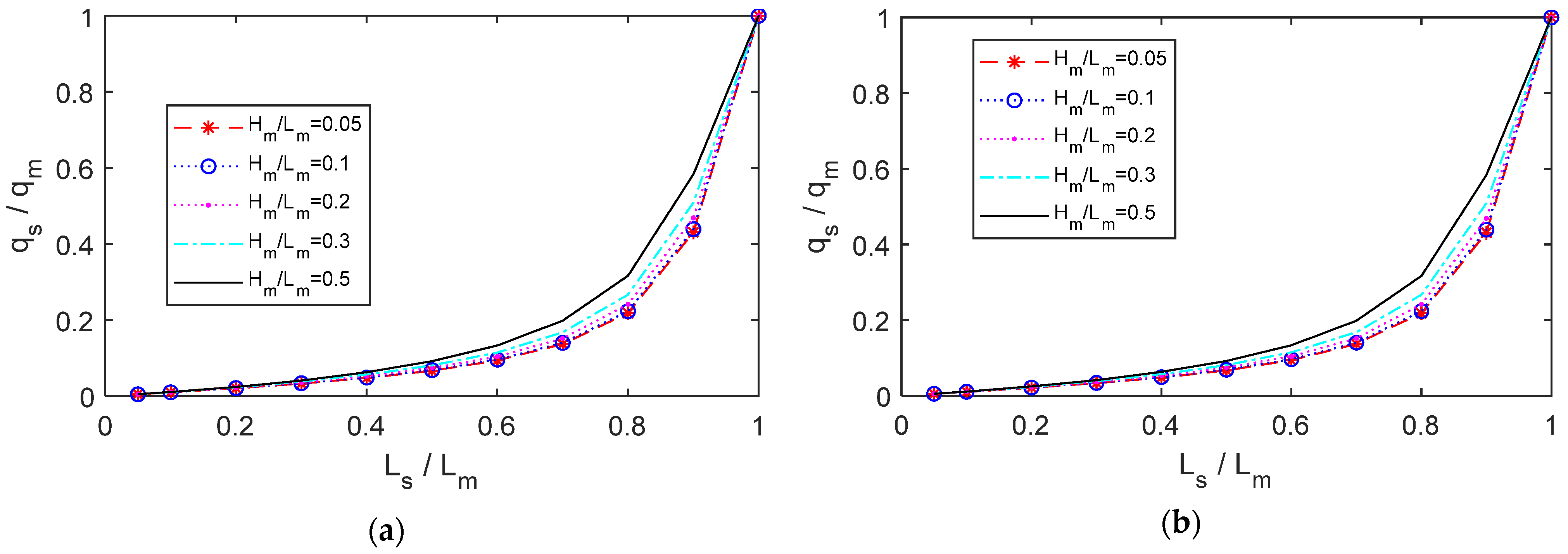
A TLD with a stable replenishment sub-tank (TLD-SRS) is proposed. The dynamic liquid pressure in the TLD is obtained with the speed potential function. Based on studies on TLCDs and TLCDAs, the relationship between the dimensionless size of the sub-tank and the maximum wave height and the dynamic liquid pressure are obtained. Thus, the TLD-SRS system with passive automatic liquid replenishment in a sub-tank is designed, using a floating ball.
(2)
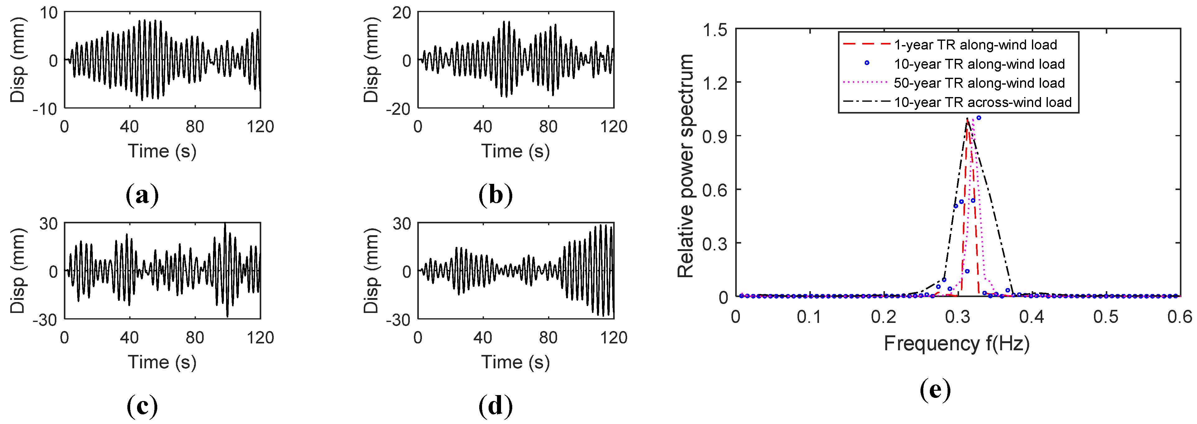
The wave height and dynamic liquid pressure in the main tank under different wind loads are obtained. A large-scale TLD shaking table experiment is conducted to study the sloshing wave height of the liquid. The roof acceleration of 1-, 10- and 50-year return periods (YRP) for along-wind loads and a 10-year return period for across-wind loads are used as the excitation load. The time history of the wave height is obtained via video recognition. The dynamic liquid pressure and the flow speed in the connecting pipe is obtained via sloshing mode decomposition.
(3)
The overshoot of the TLD with a regular floating ball replenishment device and the TLD-SRS system during the wind loads are compared. The peak accelerations of the structure with TLDs are compared considering the overshoot of liquid supplementation.
(4)
An analysis of the effect of the diameter of the connecting pipe of the TLD-SRS system on the overshoot and damping efficiency is conducted.

2. Proposed TLD with Stable Recharge Sub-Tank System

2.1. System Description

The proposed TLD-SRS aims to always keep the liquid level in the main tank maintained at the target value that is required for tuning the fundamental sloshing frequency to the structural frequency. This is achieved by connecting the main TLD tank to a sub-tank whose fundamental sloshing frequency is far away from the target value (Figure 1). The sub-tank can be set in the main tank and can also move freely out of the main tank. A pipe connects the main tank and the sub-tank. When the liquid level in the main tank drops, the liquid in the sub-tank flows through the connecting pipe to the main tank until the liquid reaches the target level. When the liquid in the main tank is over-supplemented, the liquid in the main tank flows through the connecting pipe to the sub-tank and flows out through the overflow pipe on the sub-tank.
The fundamental sloshing frequency of the liquid in a tank is related to the liquid depth and the length of the tank. The main tank and the sub-tank are designed with different length dimensions and the same liquid level. The fundamental sloshing frequency of the liquid in the main tank is near to that of the tall building, whereas the fundamental frequency of the sub-tank greatly differs from this value. Under wind loads, the vibration frequency component on the roof of the tall building is mainly the first-order frequency of the structure. When the TLD-SRS system is excited by the vibration, the liquid in the main tank sloshes in resonance, and the liquid in the sub-tank sloshes at a very small amplitude. A floating-ball control valve for controlling the automatic liquid replenishment is installed on the sub-tank. Because the liquid in the sub-tank is not excited by the excitation on the roof of the building, the sub-tank can maintain an accurate liquid replenishment state.
The floating-ball control valve can remain working without a complicated judgment system. During liquid sloshing in the main tank, the liquid flows to the sub-tank when the wave crest appears, and the liquid flows back when the wave peak appears. Under large vibrations, the main tank is in a slightly over-supplementary state, and the liquid level drops after it.
The diameter of the connecting pipe influences the supplement. The sub-tank is equivalent to a capacitor buffer, which slowly replenishes or absorbs the liquid in the main tank to maintain a stable liquid level in the main tank.

2.2. Design of the TLS-SRS

The TLCD and TLCA are similar to the TLD-SRS proposed in this paper. A TLCD is usually a U-shaped container that contains liquid, with a vertical pipe on the left side and a vertical pipe on the right side, connected by a horizontal pipe. When the diameter of the vertical pipe is small and the sloshing on the liquid free surface is much smaller than the horizontal length of a TLCD, the fundamental frequency of the TLCD is determined by the length of the U-shaped container [42,43]. However, when the diameter of the vertical column is large, the sloshing of liquid in the vertical column influences the results [44,45]. Studies have been conducted on TLCDs with asymmetric vertical liquid columns [14] and TLCDs with different cross-sectional areas of the vertical and horizontal columns [13]. Ghosh [46] proposed a tank-pipe damper system. This damper consists of two tanks connected by a pipe. When subjected to vibration, it can simultaneously exert the TLD effect of both sides of the tank and the TLCD effect of the entire connected liquid column. This damper can be designed as a tuned damper with two or three main frequencies, at which similar TMD damping effects can be exerted [13,47]. Different from those studies, the TLD-SRS system is designed with one main sloshing mode in the main tank, and the sloshing in the sub-tank and the liquid oscillation phenomenon of the system are minimized, when excited by the acceleration on the roof.
Referring to Matteo’s study [47], the dynamic equation for considering the main tank and sub-tank shaking for liquid oscillation is
y ¨ ( t ) + 1 2 ζ L ˜ e ν | y ˙ ( t ) | y ˙ ( t ) + ω ˜ 0 2 y ( t ) = b L ˜ e x ¨ g ( t )
L ˜ e = λ m H m + λ s H s γ + ν b
ω ˜ 0 = 2 g L ˜ e
γ = A m / A s
ν = A m / A c
where y(t) is the vertical liquid displacement of the sub-tank by the liquid oscillation phenomenon; ζ is the equivalent damping ratio of the liquid oscillation phenomenon; L ˜ e is the equivalent liquid column length; A m , A s and A c are the cross-sectional areas of the main tank, sub-tank and connecting pipe; λ m and λ s are the equivalent mass ratios of the main tank and sub-tank calculated by Eq(X); H m and H s are the liquid height in the main tank and sub-tank; and g is the acceleration of gravity.
The vertical liquid displacement of the sub-tank of the liquid oscillation phenomenon is
y = A 0 1 [ 1 ( ω / ω ˜ 0 ) 2 ] 2 + ( 2 ς ω / ω ˜ 0 ) 2 b L ˜ e sin ω t
When the cross-sectional area is much smaller than that of the main tank, A c < < A m , b L ˜ e 0 , 1 ( ω / ω ˜ 0 ) 2 1 and y 0 . The vertical liquid displacement by the liquid oscillation phenomenon is very small. The flow of liquid inside the connecting pipe of the TLD-SRS system mainly comes from the liquid dynamic pressure difference caused by the sloshing of two tanks. Therefore, the size difference between the main tank and the sub-tank determines the flow in the connecting pipe.
The velocity potential that satisfies the boundary conditions in a rectangle tank can be expressed in the general form as a sum of the sloshing mode [48].
Φ ( x , z , t ) = n = 1 N f n ( t ) g n ( x ) s n ( z ) = n = 1 N q ˙ n ( t ) cos n π x L cosh [ n π ( z + H ) L ] n π L sinh n π H L
The sloshing wave height is
h ( x , t ) = n = 1 N q n ( t ) cos n π x L ( n = 1 , 2 , 3 )
where q n ( t ) is the generalized coordinate wave height for liquid sloshing, H is the height of the static liquid and L is the length of the tank in the vibration direction, as shown in Figure 2.
A regular TLD with a rectangular tank can be decomposed into several parallel TMDs. The natural angular frequency of the nth TMD is given by
ω n = n π g L tanh ( n π H L ) ( n = 1 , 2 , 3 , )
The equivalent mass of the nth TMD is [49]
M n = λ n M = 8 L tanh ( n π H L ) n 3 π 3 H M ( n = 1 , 2 , 3 , )
where M is the total mass of the liquid.
The equivalent stiffness of the nth TMD is
k n = 8 n g n 2 π 2 H tanh 2 ( n π H L ) M ( n = 1 , 2 , 3 , )
The equivalent mechanical system can be related to the actual free surface response amplitude of the fundamental sloshing mode by [36,48]
q n ( t ) = Γ x r , n ( t ) = 2 n π ( 1 cos ( n π ) ) tanh ( n π H L ) x r , n ( t )
According to the dynamic equation, the liquid pressure at any point in the tank can be calculated by the velocity potential function:
p ( x , y , t ) = ρ Φ ( x , y , t ) t ρ x u ¨ g ( t ) ρ g y = ρ n = 1 N q ¨ n ( t ) cosh [ k i ( y + H ) ] n π L sinh n π H L cos n π x L ρ x u ¨ g ( t ) ρ g y
x = 0 , y = H and the pressure at the edge bottom of the tank is
p ( 0 , H , t ) = ρ i = 1 N q ¨ n ( t ) 1 n π L sinh n π H L ρ a u ¨ g ( t ) ρ g H
The flow velocity in the connecting pipe can be calculated with Bernoulli’s equation:
p ρ g + v 2 2 g + H = C
Ignoring the head loss of the connecting pipe, the flow velocity in the connecting pipe is
v = sgn ( Δ p ) 2 Δ p ρ
where
Δ p = ρ i = 1 N q ¨ n ( t ) 1 n π L sinh n π H L ρ a u ¨ g ( t )
The liquid level in the main tank during sloshing is
H R ( t ) = H + 1 BL 1 4 π D 2 v ( t ) d t = H + 1 BL 1 4 π D 2 sgn ( Δ p ) 2 Δ p ( t ) ρ d t
where D is the diameter of the connecting pipe, and B and L are the width and length of the main tank.

2.3. Design of the Connecting Pipe

For the convenience of estimating the size of the sub-tank, only the first-order mode of liquid sloshing is considered. Under the harmonic excitation u ¨ g ( t ) = A 0 sin ω t , the dynamic response of the equivalent TMD is
x r = A 0 1 ω 1 2 1 [ 1 ( ω / ω 1 ) 2 ] 2 + ( 2 ς ω / ω 1 ) 2
where ω is the circular frequency of the excitation and ω 1 is the circular frequency of the first-order fundamental equivalent mode of the TLD.
The first-order amplitude of the sloshing wave is
q 1 ( t ) = 4 π tanh ( π H 2 a ) x r , 1 ( t )
By substituting Equation (12) into Equation (13), the liquid wave height and dynamic pressure of liquid in the tank under different excitation frequencies can be calculated. Consider that the equivalent damping ratio of the tank is 5% with a flow-damping device. The non-dimentional wave height of the TLD under different excitation frequencies is shown in Figure 3. When the liquid level in the sub-tank is the same as that in the main tank, the non-dimentional wave height and dynamic pressure related to the length of the sub-tank are as shown in Figure 4. When the length of the sub-tank is less than 1/5 of that of the main tank, the relative wave height and pressure in the sub-tank is less than 0.01 and 0.003 of that in the main tank. The acceleration excitation frequency of the building roof is mainly the first order natural frequency of the structure. Under such excitation, the liquid in the sub-tank has almost not sloshing, and the liquid flow in the connecting pipe almost comes from the liquid dynamic effect in the main tank. Taking the liquid in the sub-tank as static, a shaking table experiment of the main tank was conducted to obtain the dynamic response, which includes the wave height, pressure and flow speed under wind loads. The advantage of TLD-SRS in passive replenishment is verified below.

3. Analysis of the TLD-SRS System Based on an Experiment

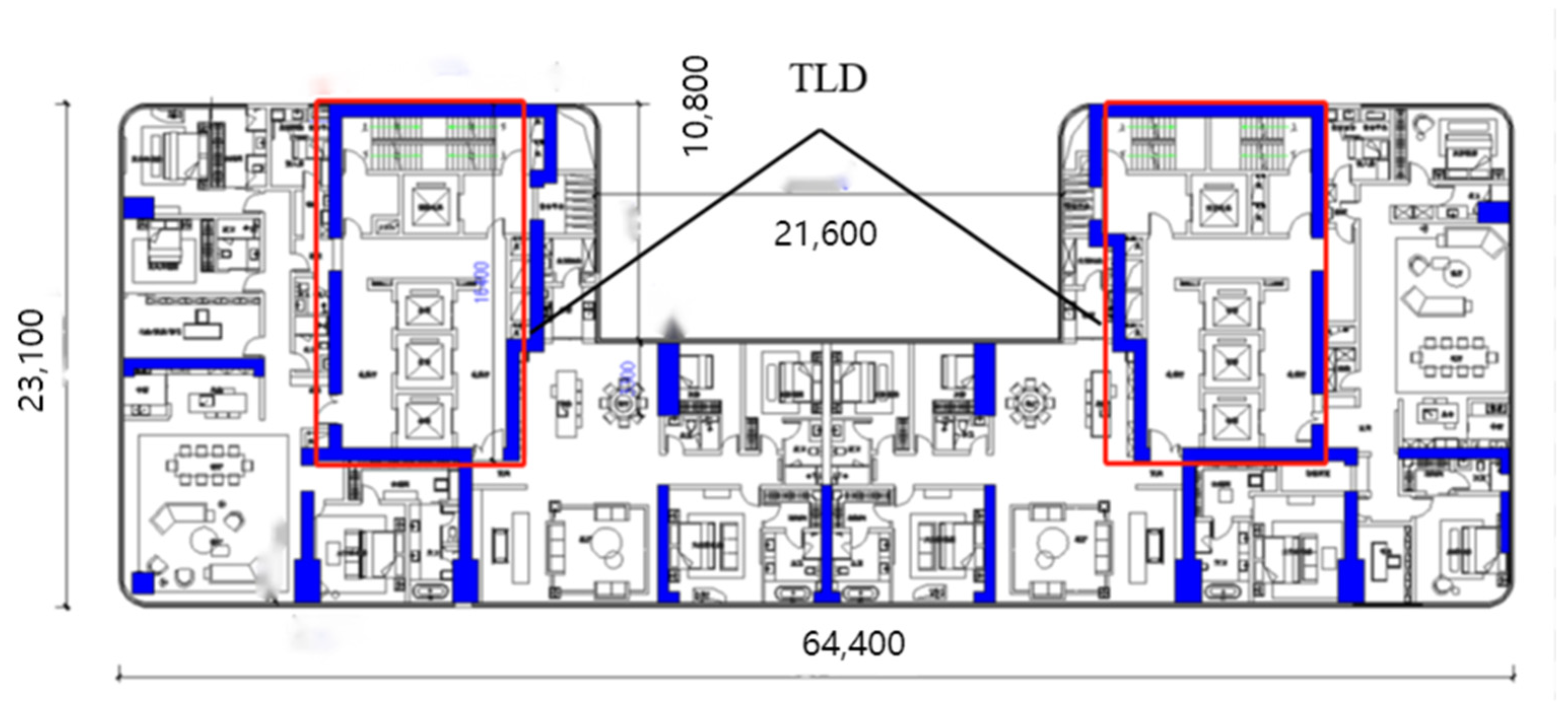
3.1. Tall Building Information

The research object is a 250 m high building. Its cross-section measures 64.4 m × 23 m, as shown in Figure 5. The fundamental frequency of the building is 0.156 s−1. Four TLDs were installed on the top of the building to improve comfort under wind loads. The dimensions of each tank are 10 m × 7 m × 2 m with a water depth of 1 m, as shown in Figure 6.

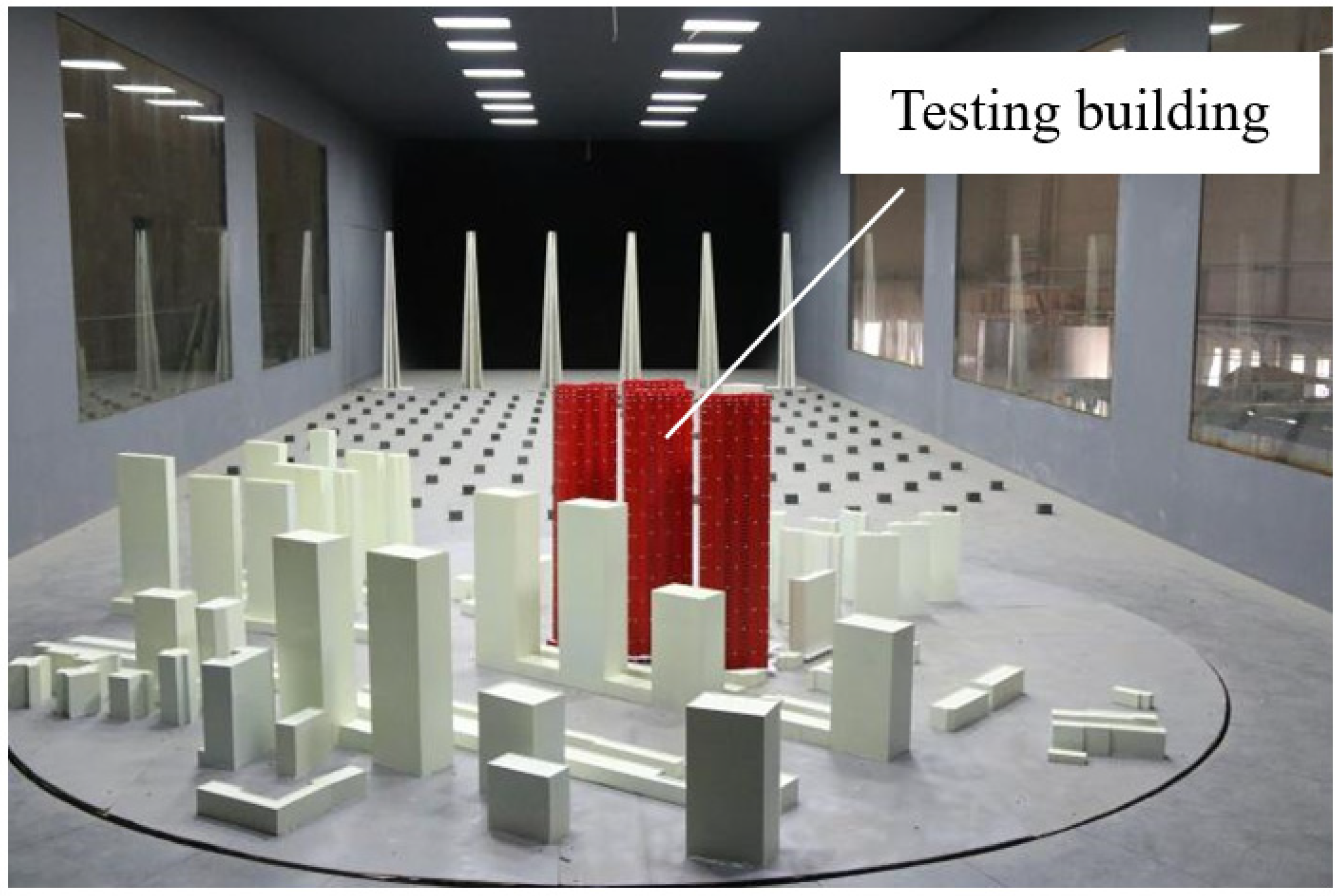
3.2. Wind Tunnel Experiment

A wind tunnel experiment was conducted at a 1:250 scale to measure the surface wind pressure of the tall building. Figure 7 shows the wind tunnel test model. Records of along-wind loads with 1-year, 10-year and 50-year return periods (YRP) and an across-wind load with a 10-year return period were obtained.

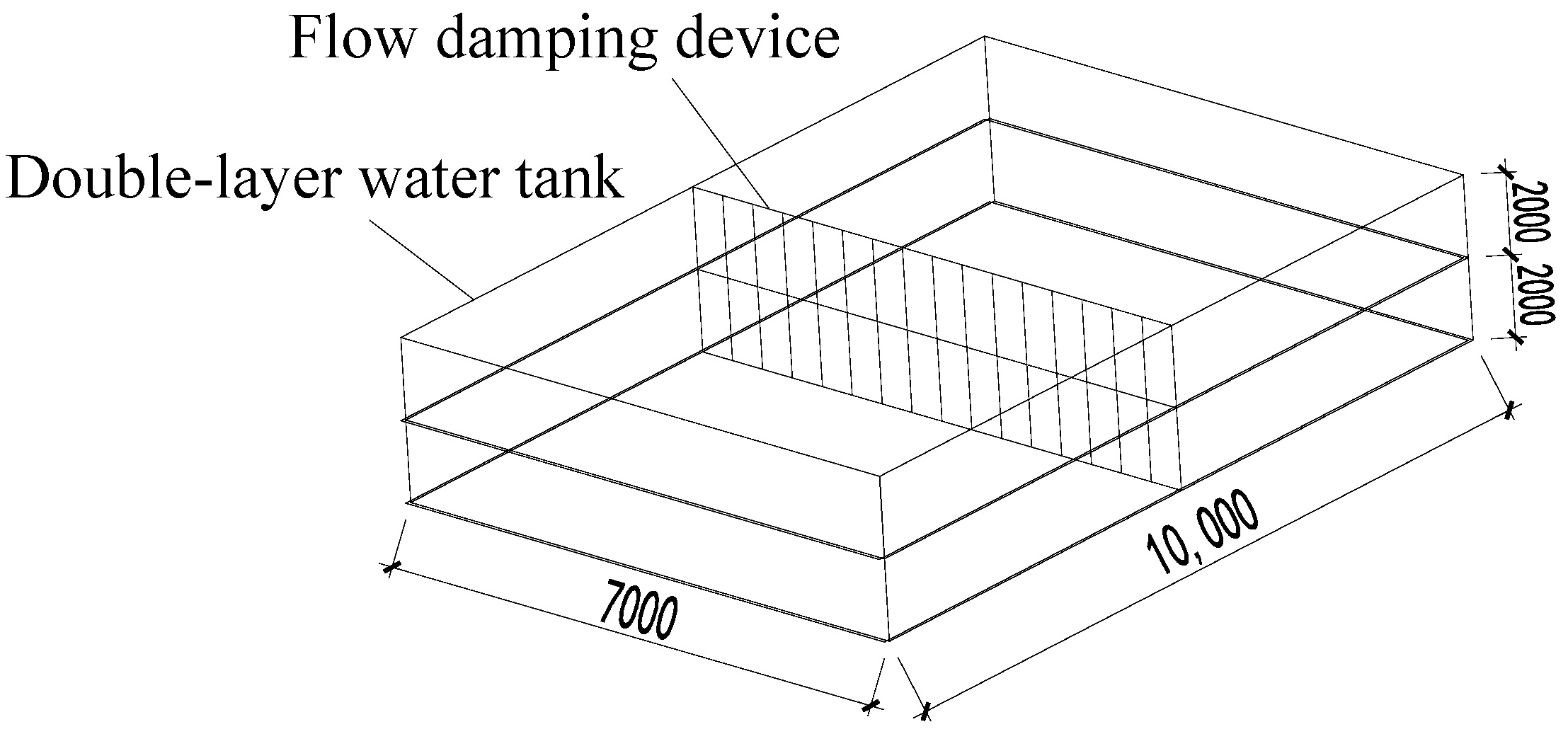
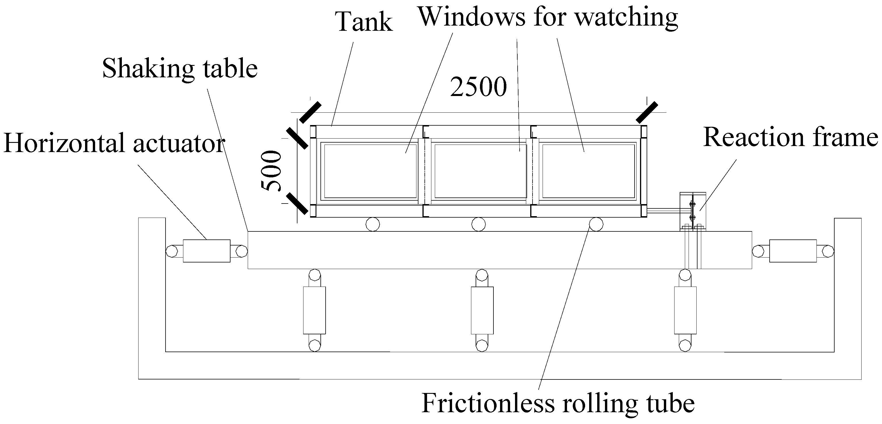
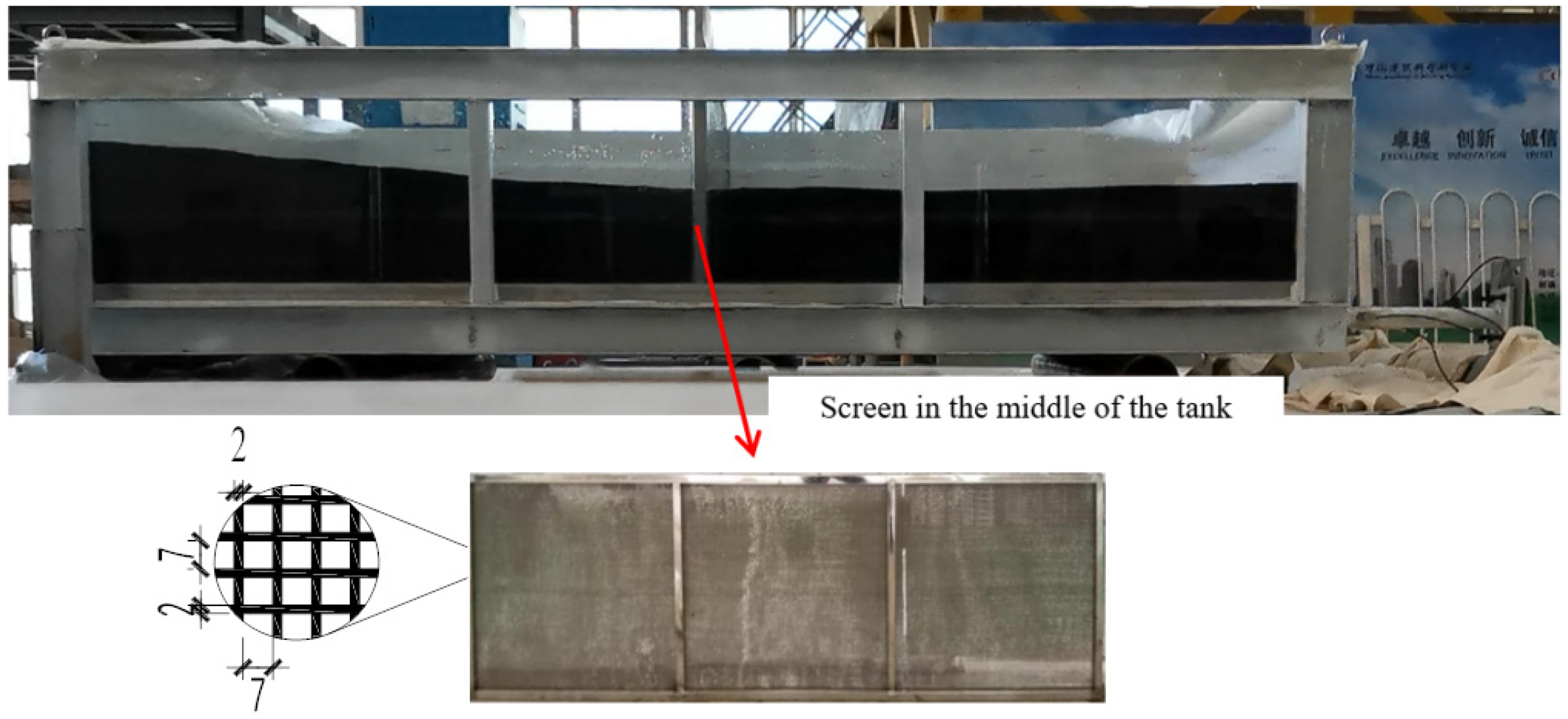
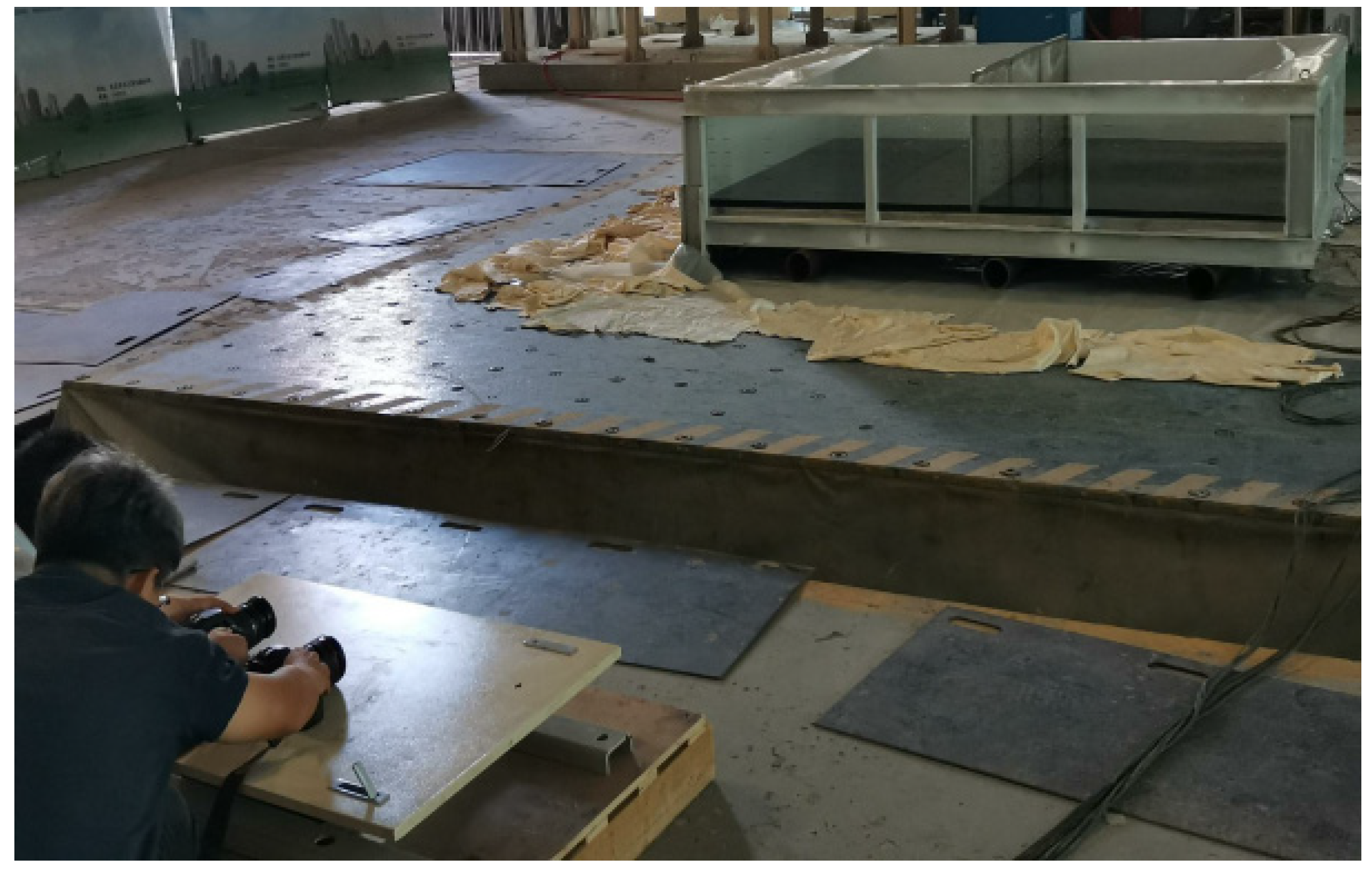
3.3. Shaking Table Experiment of TLD

A shaking table experiment was conducted with a 1:4 dimension scale and a 1:2 time scale. Figure 8 shows the experiment’s setup. The experimental tank was a 2.5 m × 1.75 m × 0.5 m rectangular tank with a water depth of 0.25 m. A net was set up in the middle of the tank as a flow-damping device, as shown in Figure 9. The fundamental sloshing frequency of the experimental TLD was 0.312 Hz. The tank was loaded with the four wind load excitation loads, and the test conditions are shown in Table 1. The input wind load time history and power spectrum of the excitation are shown in Figure 10.

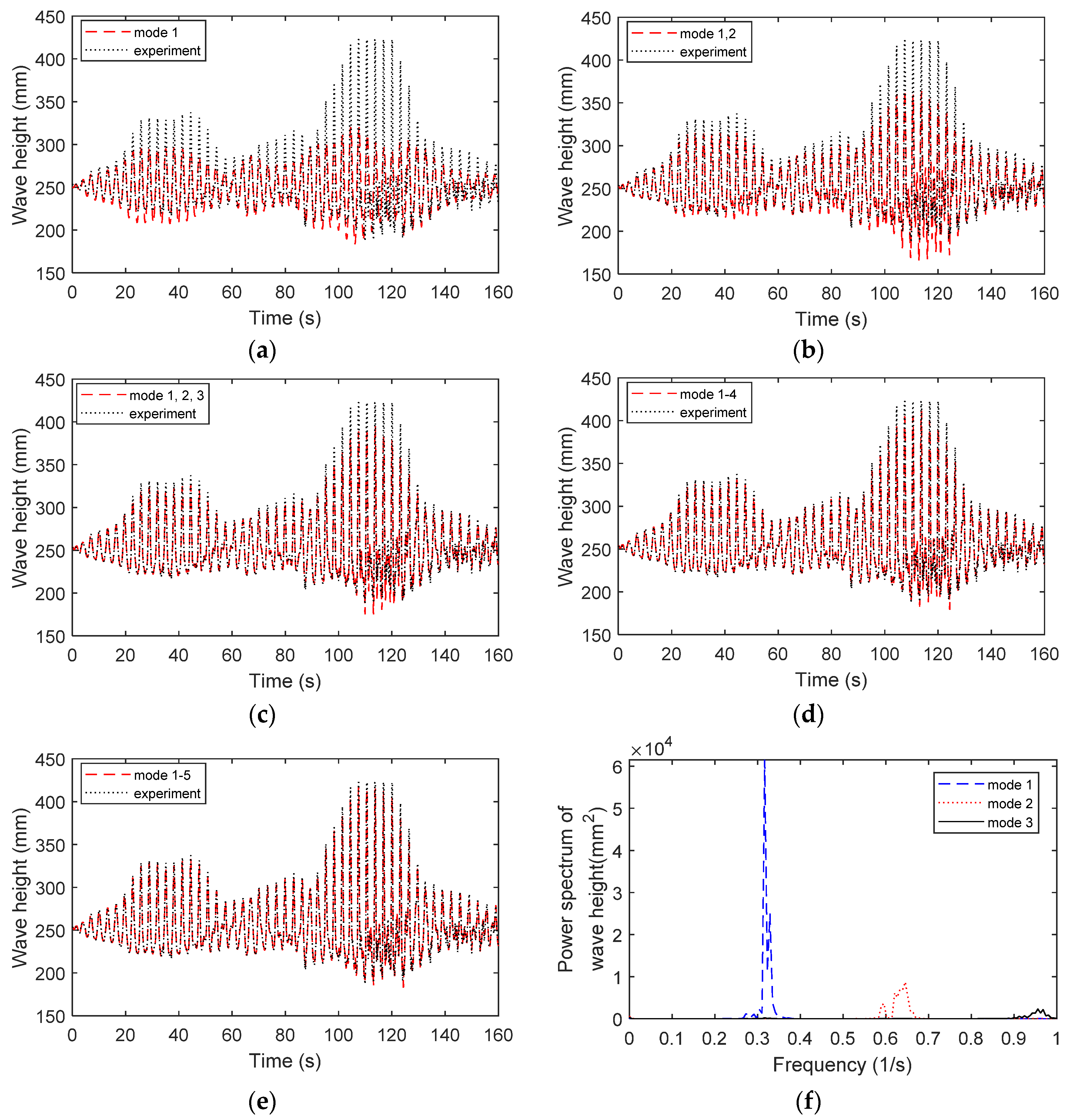
3.4. Sloshing Mode Analysis

Noncontact measurement methods are used to measure the levels of liquids. Ultrasonic sensors are used to evaluate the flowing liquid level [50] and multiphase liquid systems. In a previous study, a noncontact measurement method using a stepwise rotating galvanometer scanner was proposed to obtain the liquid level in a TLD [51].
In this study, a video recognition technique [45] was used to analyze the wave height throughout the whole vibration process. An observation glass was set on one side of the vibrating tank facing a high-definition (HD) camera. The wave height of the whole vibration process of the tank was recorded by the HD camera, as shown in Figure 11. With video recognition and baseline correction, the wave height during the experiment was obtained. The time history of the water sloshing wave height at the edge and middle of the tank under the 10 YRP across-wind load is shown in Figure 12.

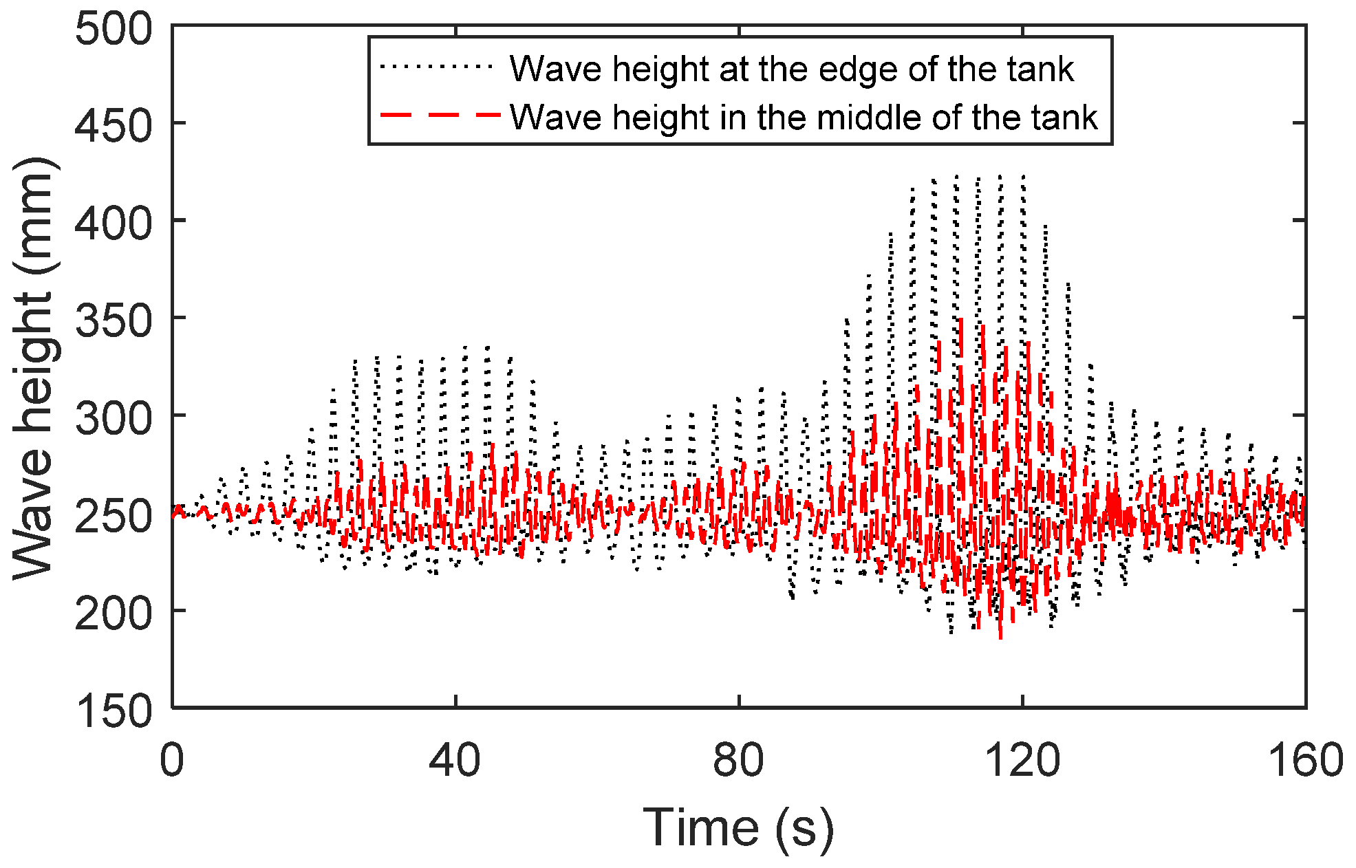
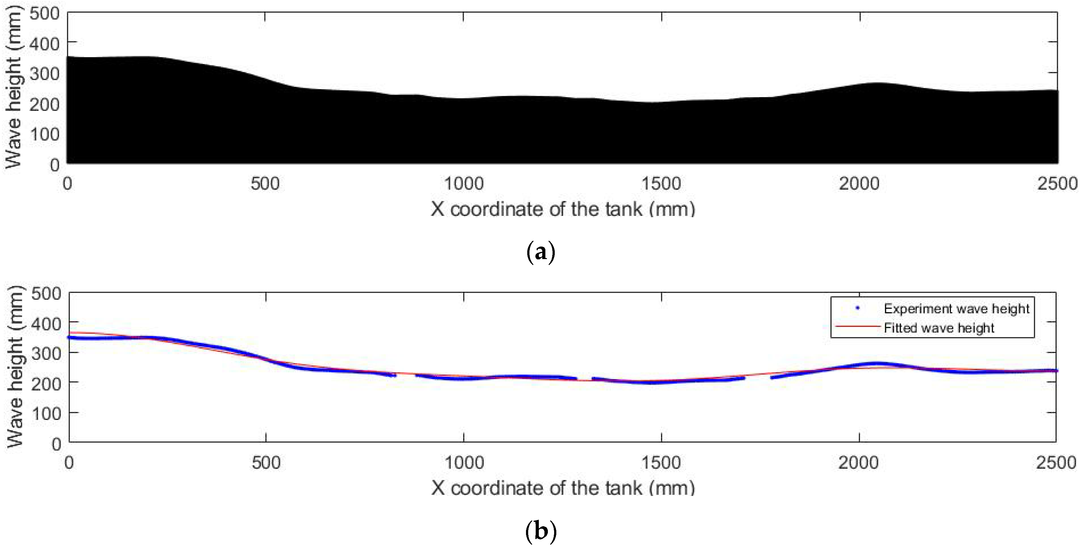
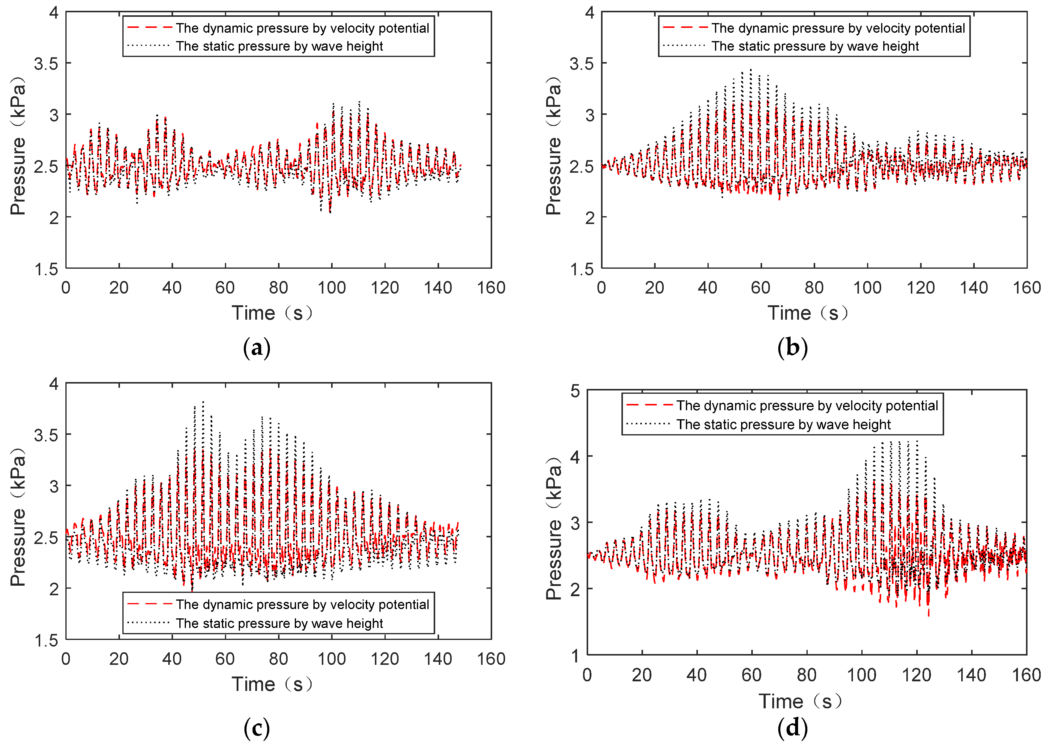
3.5. Solution of Liquid Dynamics Based on Wave Height Recognition

The response of the wave height of the TLD is mainly determined by the first three order sloshing modes [36]. The first five order sloshing modes were taken to estimate the liquid sloshing surface and to fit the wave height curve. The wave heights of each sloshing mode, calculated according to the minimum error between the fitted wave height and the actual wave height, are
ε ( t ) q n ( t ) = 0 L [ h ( x , t ) h ˜ ( x , t ) ] 2 d x q n ( t ) = 0 L [ n = 1 5 q n ( t ) cos n π x L h ˜ ( x , t ) ] 2 d t q n ( t ) = 0 n = 1 , 2 , 3 , 4 , 5
where h ˜ ( x , t ) is the actual wave height of the free surface of the sloshing liquid.
Figure 13b shows the wave height fitted with the first five order modes according to Equation (20). Figure 14a–e show a comparison between the actual experimental wave height and the fitted wave height considering the different number of modes under 10 YRP across-wind. With more modes, the fitted wave height is closer to the actual experimental wave height. The root-mean-square (RMS) errors of the fitted wave height considering different modes under four kinds of wind loads are shown in Table 2. The maximum root-mean-square error of the first three modes is not more than 8%, and the maximum root mean square error of the first five modes is not more than 4%. Figure 14f shows that the first mode provides the highest contribution to the wave height, and the contributions of the second and third modes decrease in turn.

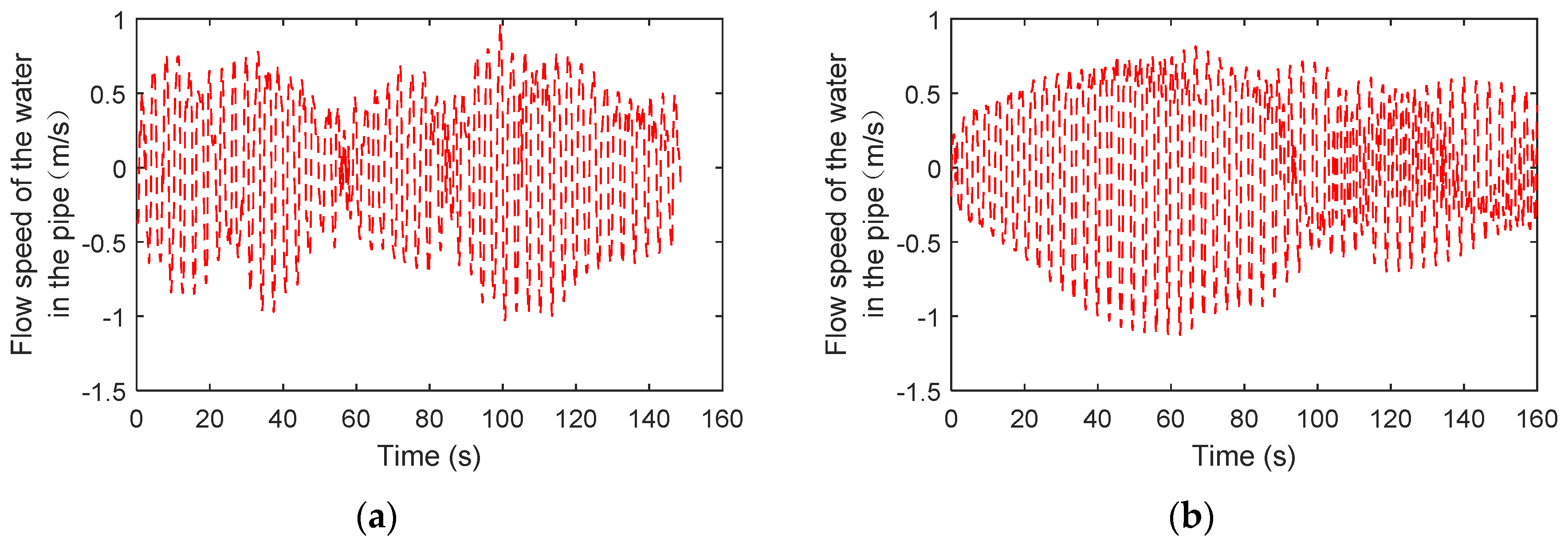
3.6. Liquid Flow between the Main Tank and Sub-Tank

Bringing the time history of the wave height into Equation (6), the velocity potential function of the TLD can be obtained. The liquid pressure at any position inside the tank is calculated with Equation (14). The hydrostatic pressure and dynamic liquid pressure at the bottom edge of the tank are shown in Figure 15. This shows that the static liquid pressure and the actual dynamic liquid pressure are quite different. The flow speed in the connecting pipe should be calculated using the dynamic liquid pressure. The flow velocity in the connecting pipe is calculated with Equation (17). The time history of the liquid flow velocity in the connecting pipe is presented in Figure 16. The nonlinear relationship curve between the flow velocity and wave height is presented in Figure 17. The flow velocity is more sensitive to wave height when the liquid is flowing out of the main tank and the flow speed is in a positive direction.

4. Overshoot of Liquid Supplementation

4.1. Overshoot of the Regular Liquid Replenishment Device

Regular tanks usually use a floating ball to replenish liquid, as shown in Figure 18. The floating ball is located in the middle of the tank where the liquid level fluctuation is relatively small. Due to the nonlinear sloshing of liquid, higher-order sloshing modes coupled with the first-order sloshing mode are excited. The liquid level in the middle of the tank also fluctuates up and down. Once the liquid level at the location of the floating ball drops, the blocking switch of the liquid inlet pipe is opened. The liquid inlet pipe replenishes liquid in the tank until the liquid level reaches the target liquid level. When the trough of the liquid reaches the position of the floating ball, the liquid replenishment device is mistakenly started. The actual static liquid level in the tank becomes higher than the target level. If the sloshing of the liquid in the tank is more intense, the trough of the sloshing liquid surface is lower, and the static liquid level is further exceeded.

4.2. Overcompensation of the Proposed Liquid Replenishment

The proposed liquid replenishment system in this study is shown in Figure 1. The inlet pipe is connected to the sub-tank. The same floating ball as that in Section 4.1 is used as the liquid replenishment control device of the sub-tank. Under the acceleration excitation on the roof of the tall building, the liquid in the sub-tank almost always does not slosh when the length of the sub-tank is less than 1/5 of that of the main tank. The liquid level in the sub-tank can always remain at the target liquid level without interference from sloshing. During the sloshing process of the main tank, when the dynamic liquid pressure at the position of the connecting pipe increases, the liquid flows from the main tank to the sub-tank. When the dynamic liquid pressure decreases, the liquid flows back to the main tank.
The overshoot of the TLD-SRS is calculated with a connecting pipe diameter of 50 mm. Figure 19 shows the overshoot of TLD using the regular supplement device with a floating ball and the proposed TLD-SRS system under the four wind loads. The maximum overshoot is shown in Table 3. Using the regular supplement device, the maximum overshoot is 17%. Using the TLD-SRS system, the maximum overshoot can be controlled within 2%. Figure 20 shows the time history of sloshing waves for TLDs with the two kinds of liquid supplement. The liquid level in the tank increases significantly while using the regular supplement device.

4.3. Damping Effect Considering Overcompensation

The acceleration response at the top of a tall building with TLD is calculated. The structural dynamics equation with TLD is shown in Equation (21). The equivalent frequency, mass and stiffness of the TLD are calculated using Equations (8)–(10).
[ M s 0 0 m r ] { X ¨ s x ¨ r } + [ C s 0 0 c r ] { X ˙ s x ˙ r } + [ K s * k r k r k r ] { X s x r } = { F w 0 }
K s * = K s + [ 0 k r ] = [ k 11 k 12 k 1 n k 21 k 22 k 2 n k n 1 k n 2 k n n + k r ]
where M s is the mass matrix, C s is the damping matrix, and K s is the stiffness matrix of the building.
Figure 21 shows the time history of the acceleration at the roof of the building with TLD using a regular supplement device and TLD-SRS system. The RMS of the acceleration on the roof of the building is calculated without TLD, with TLD keeping at an optimal liquid level, with a regular supplement device and with the TLD-SRS system, as shown in Table 4. The damping rate of the TLD is significantly improved after adopting the proposed TLD-SRS system compared with the regular supplement device.
The passive liquid level control device (TLD-FB) proposed by Tanmoy [41] provided a reduction of 25.8% in RMS displacement with white noise excitation. The TLD-SRS proposed above provides a similar reduction. The RMS acceleration on the top of the building reduces it by 17~36% with TLD keeping at an optimal liquid level, by 14~33% with the TLD-SRS system and by 10~22% with TLD installed with a regular supplement device with different wind loads. The TLD-SRS system can significantly improve the damping effect of the TLD. The damping effect of TLD-SRS is close to the TLD keeping at optimal liquid level with the same mass. The emergency tank is converted into a TLD-SRS with no more complex liquid supplement devices.

4.4. Overshoot with Different Pipe Dimensions

The influence of connecting the pipe diameter on the overshoot of liquid supplementation is considered with the connecting pipe diameters of 20, 40 and 50 mm. Figure 22 shows the overcompensation with different pipe diameters. Taking the RMS of the acceleration at the top of the building when the TLD always maintains the optimal liquid level as the relative quantity reference, Figure 23 shows the relative RMS acceleration value when using different-diameter connecting pipes. When the diameter of the connecting pipe is small enough, the overcompensation of the TLD-SRS system is very small, and the damping efficiency is close to the optimal TLD damping rate.

5. Conclusions

The liquid supplement of the tank for emergency use is usually controlled by a floating ball to ensure that the liquid level is not lower than the minimum target liquid level and that the over supplementation of the liquid in the tank is not really concerned. The overshoot of the liquid influences the damping effect because of mistuning, when regarding the tank as a TLD. In this paper, a passive liquid replenishment system (TLD-SRS) is proposed to avoid the misactivation of liquid supplementation.
Integrating existing liquid storage and supply systems in buildings with TLDs to reduce the effective cost of TLDs is a significant topic. Like the TLD-FB [41], which converts liquid storage into a TLD via passive liquid control, the emergency tank is easily converted into a TLD-SRS with no more complex liquid supplement devices. Using an additional sub-tank whose sloshing frequency differs from that of the main tank, the overshoot in the main tank is greatly reduced. The size of the sub-tank and the connecting pipe are selected based on the dynamic pressure obtained in the shaking table experiment. The advantages of the overshoot and the vibration control effect of the TLD-SRS are verified in a tall building. The conclusions of this study are as follows:
(1)
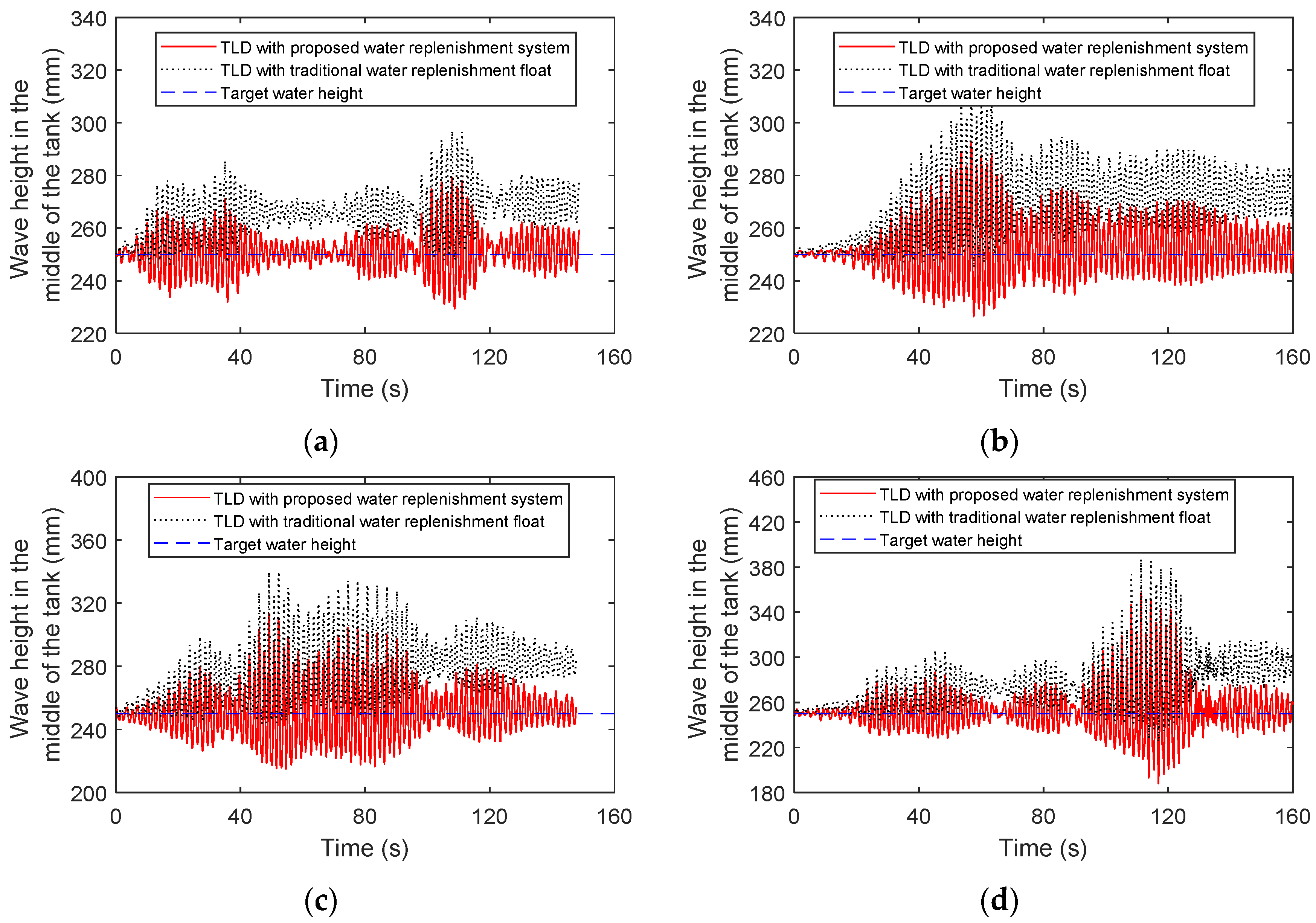
A shaking table experiment of TLDs is conducted to capture the sloshing wave height time history with wind loads. By obtaining the velocity potential from the wave height, dynamic pressure, static pressure, wave height of each mode and the flow velocity in the connecting pipe of the TLD-SRS system are presented. The dynamic liquid pressure is different from the static liquid pressure, and the former determines the flow velocity in the connecting pipe during the shaking process.
(2)
The sloshing liquid wave height obtained from the experiment can be decomposed in the first three or five orders of sloshing modes. The root-mean-square error between the wave height represented by the first five order modes and the actual wave height is less than 4%, and the root-mean-square error between the TLD swaying wave height represented by the first three order modes and the actual wave height is less than 8%. The liquid sloshing in a TLD is mainly determined by the first five sloshing modes.
(3)
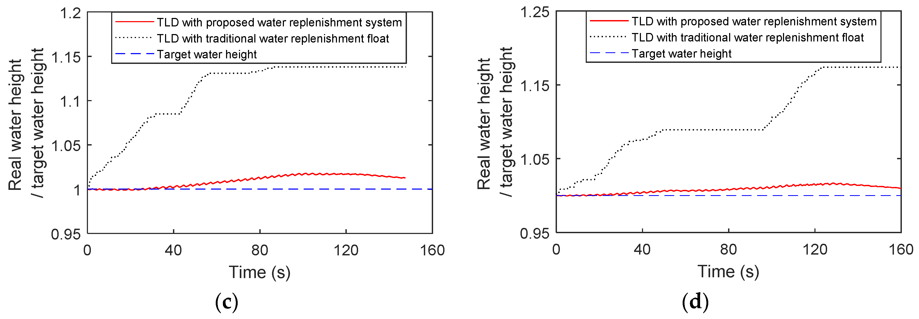
The overshoot of liquid supplementation by the TLD-SRS system and by the regular floating ball liquid replenishment device are compared with wind loads. During the liquid sloshing in the TLD, the water in the sub-tank of the TLD-SRS almost remains without sloshing to avoid misactivation, and the regular replenishment device may be frequently misactivated. The TLD-SRS can reduce the maximum overshoot by 15% (using the regular floating ball liquid replenishment device) to 2%.
(4)
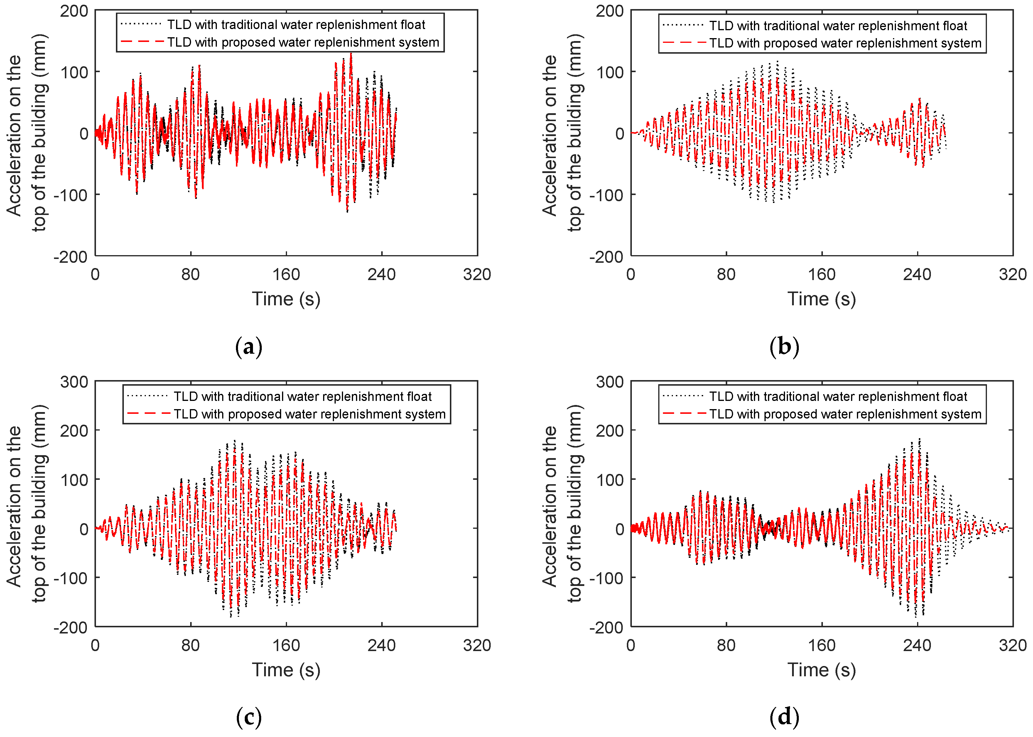
The TLD-SRS system can significantly improve the damping effect of the TLD considering the overshoot during sloshing. The RMS acceleration on the top of the building reduces it by 17~36% with the TLD keeping at an optimal liquid level, by 14~33% with the TLD-SRS system and by 10~22% with the TLD installed with a regular supplement device with different wind loads.
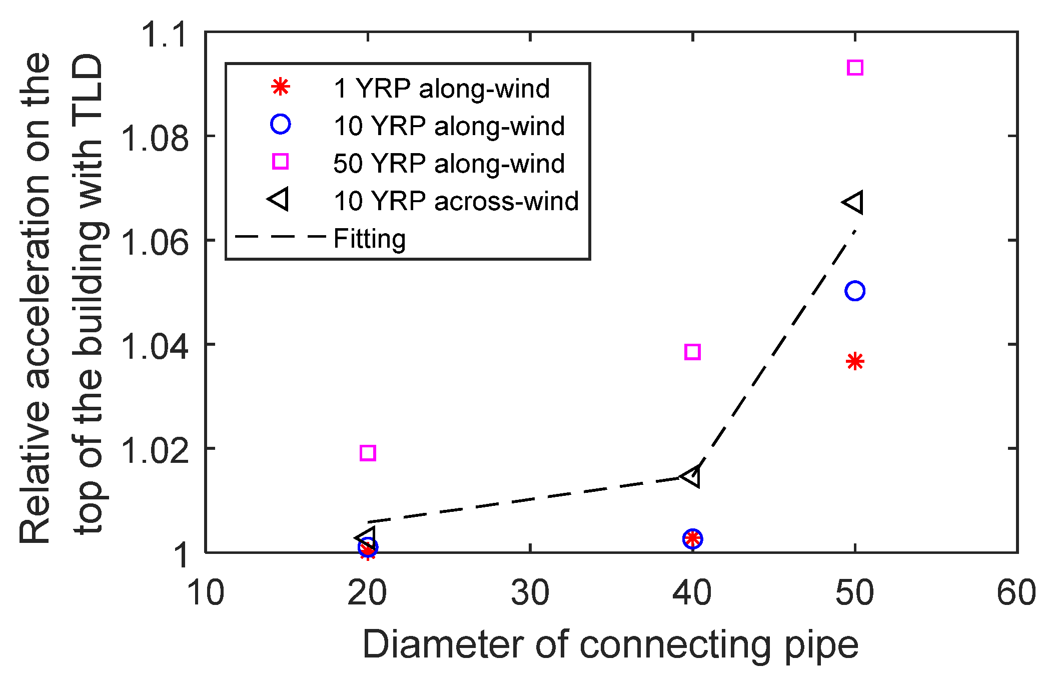
(5)
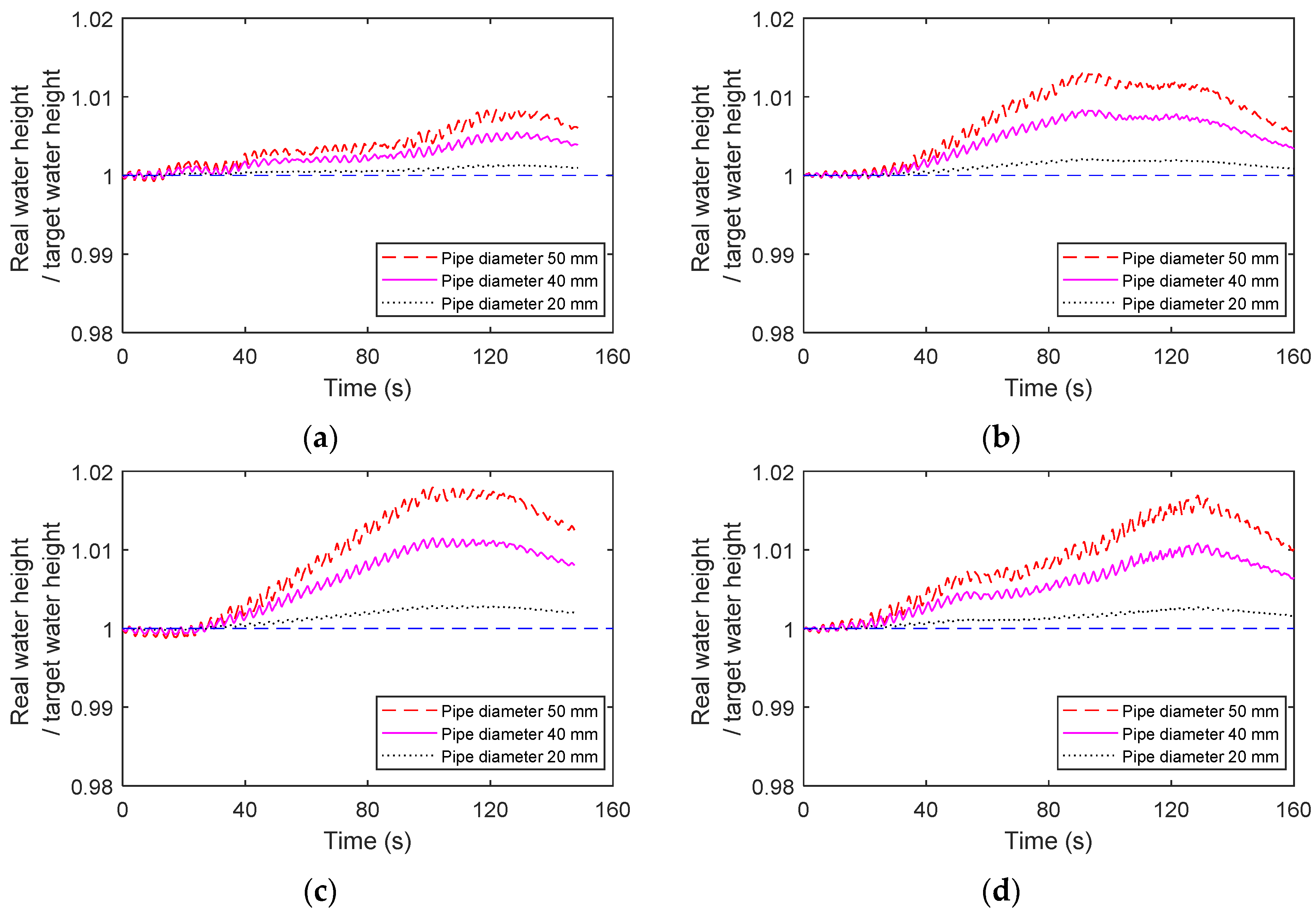
As the diameter of the connecting pipe in the TLD-SRS becomes smaller, the overshoot of the TLD also becomes smaller, considering the liquid sloshing under wind loads. When the diameter of the connecting pipe is 50 mm, the acceleration of the structure can already reach below 1.08 times of the optimal control acceleration, which is recommended in most situations. When there is a higher control requirement, it is a good choice to use a connecting pipe of 40 mm diameter, and the relative acceleration can reduce to 1.02.

Author Contributions

C.X.: Conceptualization, Resources, Project administration. Z.W.: Investigation, Methodology, Formal analysis, Writing. K.C.: Validation, Resources, Funding acquisition, Supervision. Y.T.: Investigation, Validation. Y.Y.: Software, Data curation, Visualization. All authors have read and agreed to the published version of the manuscript.

Funding

This research was funded by the Beijing Natural Science Foundation (No. 8212019) and by Special Funding of the China Academy of Building Research (20220118330730013). Any opinions, findings, conclusions or recommendations expressed in this material are those of the authors and do not necessarily reflect the views of the Foundations.

Data Availability Statement

The raw/processed data required to reproduce these findings cannot be shared at this time as the data also forms part of an ongoing study.

Acknowledgments

The authors would like to thank the partners at Congzhen Xiao Master Studio and the wind engineering team at the China Academy of Building Research for the discussed suggestions.

Conflicts of Interest

The authors declare that they have no known competing financial interests or personal relationships that could have appeared to influence the work reported in this paper.

References

  1. Sharma, A.; Mittal, H.; Gairola, A. Mitigation of wind load on tall buildings through aerodynamic modifications: Review. J. Build. Eng. 2018, 18, 180–194. [Google Scholar] [CrossRef]
  2. Jafari, M.; Alipour, A. Methodologies to mitigate wind-induced vibration of tall buildings: A state-of-the-art review. J. Build. Eng. 2021, 33, 101582. [Google Scholar] [CrossRef]
  3. Yue, Y.; Li, C.; Jia, K.; Zhang, Y.; Tian, J. Optimization of the Seismic Performance of a Steel-Concrete Wind Turbine Tower with the Tuned Mass Damper. Buildings 2022, 12, 1474. [Google Scholar] [CrossRef]
  4. Huang, H.C. Efficiency of the motion amplification device with viscous dampers and its application in high-rise buildings. Earthq. Eng. Eng. Vib. 2009, 8, 521–536. [Google Scholar] [CrossRef]
  5. Sato, D.; Chang, T.; Chen, Y. Effects of Different Frequency Sensitivity Models of a Viscoelastic Damper on Wind-Induced Response of High-Rise Buildings. Buildings 2022, 12, 2182. [Google Scholar] [CrossRef]
  6. Takewaki, I.; Murakami, S.; Yoshitomi, S.; Tsuji, M. Fundamental mechanism of earthquake response reduction in building structures with inertial dampers. Struct. Control Health Monit. 2012, 19, 590–608. [Google Scholar] [CrossRef]
  7. Bian, Y.; Liu, X.; Sun, Y.; Zhong, Y. Optimized Design of a Tuned Mass Damper Inerter (TMDI) Applied to Circular Section Members of Transmission Towers. Buildings 2022, 12, 1154. [Google Scholar] [CrossRef]
  8. Zhang, S.; Hu, Y.; Zhang, C.; Li, S.; Tan, P. Performance-Based Compositive Passive Control Analysis of Multi-Tower Building with Chassis: Optimization of Kelvin-Voigt Dampers. Buildings 2022, 12, 137. [Google Scholar] [CrossRef]
  9. Ashasi-Sorkhabi, A.; Malekghasemi, H.; Ghaemmaghami, A.; Mercan, O. Experimental investigations of tuned liquid damper-structure interactions in resonance considering multiple parameters. J. Sound Vib. 2017, 388, 141–153. [Google Scholar] [CrossRef]
  10. Ishikawa, S.; Kondou, T.; Matsuzaki, K.; Yamamura, S. Analysis of nonlinear shallow water waves in a tank by concentrated mass model. J. Sound Vib. 2016, 371, 171–182. [Google Scholar] [CrossRef]
  11. An, Y.; Wang, Z.; Ou, G.; Pan, S.; Ou, J. Vibration Mitigation of Suspension Bridge Suspender Cables Using a Ring-Shaped Tuned Liquid Damper. J. Bridge Eng. 2019, 24, 4019020. [Google Scholar] [CrossRef]
  12. Hemmati, A.; Oterkus, E.; Barltrop, N. Fragility reduction of offshore wind turbines using tuned liquid column dampers. Soil Dyn. Earthq. Eng. 2019, 125, 105705. [Google Scholar] [CrossRef]
  13. Konar, T.; Ghosh, A.D. Bimodal vibration control of seismically excited structures by the liquid column vibration absorber. J. Vib. Control 2012, 19, 385–394. [Google Scholar] [CrossRef]
  14. Smith, M.J.; Kobine, J.J.; Davidson, F.A. Free and forced motion in an asymmetric liquid-column oscillator. Proc. R. Soc. A Math. Phys. Eng. Sci. 2008, 464, 905–922. [Google Scholar] [CrossRef]
  15. Fei, Z.; Jinting, W.; Feng, J.; Liqiao, L. Control performance comparison between tuned liquid damper and tuned liquid column damper using real-time hybrid simulation. Earthq. Eng. Eng. Vib. 2019, 18, 695–701. [Google Scholar] [CrossRef]
  16. Zhang, Z. Understanding and exploiting the nonlinear behavior of tuned liquid dampers (TLDs) for structural vibration control by means of a nonlinear reduced-order model (ROM). Eng. Struct. 2022, 251, 113524. [Google Scholar] [CrossRef]
  17. Rimal, H.; Pradhan, P.; Gautam, D.; Rupakhety, R. Seismic Fragility of Aging Elevated Water Tank with Smooth Bars Considering Soil Structure Interaction. Buildings 2023, 13, 4. [Google Scholar] [CrossRef]
  18. Konar, T.; Ghosh, A.D. Flow Damping Devices in Tuned Liquid Damper for Structural Vibration Control: A Review. Arch. Comput. Methods Eng. 2021, 28, 2195–2207. [Google Scholar] [CrossRef]
  19. Jin, L.; Li, B.; Lin, S.; Li, G. Optimal Design Formula for Tuned Mass Damper Based on an Analytical Solution of Interaction between Soil and Structure with Rigid Foundation Subjected to Plane SH-Waves. Buildings 2023, 13, 17. [Google Scholar] [CrossRef]
  20. Ocak, A.; Bekdaş, G.; Nigdeli, S.M.; Kim, S.; Geem, Z.W. Optimization of Tuned Liquid Damper Including Different Liquids for Lateral Displacement Control of Single and Multi-Story Structures. Buildings 2022, 12, 377. [Google Scholar] [CrossRef]
  21. Roy, A.; Zhang, Z.; Ghosh, A.D.; Basu, B. On the nonlinear performance of a tuned sloshing damper under small amplitude excitation. J. Vib. Control 2019, 25, 2695–2705. [Google Scholar] [CrossRef]
  22. Tait, M.J.; Isyumov, N.; El, D.A.A. Performance of Tuned Liquid Dampers. J. Eng. Mech. 2008, 134, 417–427. [Google Scholar] [CrossRef]
  23. Roy, A.; Ghosh, A.D.; Chatterjee, S. Influence of tuning of passive TLD on the seismic vibration control of elevated water tanks under various tank-full conditions. Struct. Control Health Monit. 2017, 24, e1924. [Google Scholar] [CrossRef]
  24. Konar, T.; Ghosh, A. A review on various configurations of the passive tuned liquid damper. J. Vib. Control 2022, 160766109. [Google Scholar] [CrossRef]
  25. Kickert, W.J.M.; Van Nauta Lemke, H.R. Application of a fuzzy controller in a warm water plant. Automatica 1976, 12, 301–308. [Google Scholar] [CrossRef]
  26. Erschler, J.; Roubellat, F.; Vernhes, J.P. Automation of a hydroelectric power station using variable-structure control systems. Automatica 1974, 10, 31–36. [Google Scholar] [CrossRef]
  27. Kumar, B.; Rajita, G.; Mandal, N. A Review on Capacitive-Type Sensor for Measurement of Height of Liquid Level. Meas. Control 2014, 47, 219–224. [Google Scholar] [CrossRef]
  28. Chamorro-Atalaya, O.; Arce-Santillan, D.; Morales-Romero, G.; Quispe-Andía, A.; Trinidad-Loli, N.; Auqui-Ramos, E.; León-Velarde, C.; Gutiérrez-Zubieta, E. Level Transducer Circuit Implemented by Ultrasonic Sensor and Controlled with Arduino Nano for its Application in a Water Tank of a Fire System. Int. J. Adv. Comput. Sci. Appl. 2021, 12, 464–471. [Google Scholar] [CrossRef]
  29. Kodathala, V.; Kumar, K.; Vunnam, R.C.; Raju, C. Water Level Management Using Ultrasonic Sensor (Automation). Int. J. Comput. Sci. Eng. 2018, 6, 799–804. [Google Scholar] [CrossRef]
  30. Getu, B.; Attia, H. Automatic water level sensor and controller system. In Proceedings of the 2016 5th International Conference on Electronic Devices, 6–8 December 2016, Ras Al Khaimah, United Arab Emirates, 6–8 December 2016; pp. 1–4. [Google Scholar]
  31. Xu, J.; Hang, C.; Liu, C. Parallel structure and tuning of a fuzzy PID controller. Automatica 2000, 36, 673–684. [Google Scholar] [CrossRef]
  32. Ribeiro, J.M.S.; Santos, M.F.; Carmo, M.J.; Silva, M.F. Comparison of PID controller tuning methods: Analytical/classical techniques versus optimization algorithms. In Proceedings of the 2017 18th International Carpathian Control Conference (ICCC), Sinaia, Romania, 28–31 May 2017; pp. 533–538. [Google Scholar]
  33. Roy, P.; Kar, B.; Roy, B.K. Fractional Order PI-PD Control of Liquid Level in Coupled Two Tank System and its Experimental Validation. Asian J. Control 2017, 19, 1699–1709. [Google Scholar] [CrossRef]
  34. Sundaravadivu, K.; Arun, B.; Saravanan, K. Design of Fractional Order PID controller for liquid level control of spherical tank. In Proceedings of the 2011 IEEE International Conference on Control System, Computing and Engineering, Penang, Malaysia, 25–27 November 2011; pp. 291–295. [Google Scholar]
  35. Shah, P.; Agashe, S. Review of fractional PID controller. Mechatronics 2016, 38, 29–41. [Google Scholar] [CrossRef]
  36. Love, J.S.; Tait, M.J. Frequency domain prediction of peak nonlinear wave heights of structure-TLD systems. Eng. Struct. 2019, 194, 1–10. [Google Scholar] [CrossRef]
  37. Ibrahim, R.A.; Pilipchuk, V.N.; Ikeda, T. Recent Advances in Liquid Sloshing Dynamics. Appl. Mech. Rev. 2001, 54, 133–199. [Google Scholar] [CrossRef]
  38. Love, J.S.; Tait, M.J. Nonlinear simulation of a tuned liquid damper with damping screens using a modal expansion technique. J. Fluid. Struct. 2010, 26, 1058–1077. [Google Scholar] [CrossRef]
  39. Ibrahim, R.A. Liquid Sloshing Dynamics Theory and Applications; Cambridge University Press: Cambridge, UK, 2005. [Google Scholar]
  40. Kareem, A.; Yalla, S.; Mccullough, M. Sloshing-Slamming Dynamics–S2–Analogy for Tuned Liquid Dampers. In Vibro-Impact Dynamics of Ocean Systems and Related Problems; Ibrahim, R.A., Babitsky, V.I., Okuma, M., Eds.; Springer: Berlin/Heidelberg, Germany, 2009; pp. 123–133. ISBN 978-3-642-00629-6. [Google Scholar]
  41. Konar, T.; Ghosh, A. Development of a novel tuned liquid damper with floating base for converting deep tanks into effective vibration control devices. Adv. Struct. Eng. 2021, 24, 401–407. [Google Scholar] [CrossRef]
  42. Espinoza, G.; Carrillo, C.; Suazo, A. Analysis of a tuned liquid column damper in non-linear structures subjected to seismic excitations. Lat. Am. J. Solids Stru. 2018, 15. [Google Scholar] [CrossRef]
  43. Dziedziech, K.; Staszewski, W.; Ghosh, A.; Basu, B.; Uhl, T. Characterisation of instantaneous dynamic parameters in vibration analysis of tuned liquid column dampers. Nonlinear Dynam. 2017, 90, 717–731. [Google Scholar] [CrossRef]
  44. Chakraborty, S.; Debbarma, R.; Marano, G.C. Performance of tuned liquid column dampers considering maximum liquid motion in seismic vibration control of structures. J. Sound Vib. 2012, 331, 1519–1531. [Google Scholar] [CrossRef]
  45. Das, A.; Maity, D.; Bhattacharyya, S.K. Characterization of liquid sloshing in U-shaped containers as dampers in high-rise buildings. Ocean Eng. 2020, 210, 107462. [Google Scholar] [CrossRef]
  46. Ghosh, A.; Saha, P.; Basu, B. Study of a Tank-Pipe Damper System for Seismic Vibration Control of Structures. In Proceedings of the 15th World Conference on Earthquake Engineering, Lisboa, Portugal, 24–28 September 2012. [Google Scholar]
  47. Di Matteo, A.; Lo Iacono, F.; Navarra, G.; Pirrotta, A. Innovative modeling of Tuned Liquid Column Damper motion. Commun. Nonlinear Sci. 2015, 23, 229–244. [Google Scholar] [CrossRef]
  48. Tait, M.J. Modelling and preliminary design of a structure-TLD system. Eng. Struct. 2008, 30, 2644–2655. [Google Scholar] [CrossRef]
  49. Li, Y.; Wang, J. A supplementary, exact solution of an equivalent mechanical model for a sloshing fluid in a rectangular tank. J. Fluid. Struct. 2012, 31, 147–151. [Google Scholar] [CrossRef]
  50. Pereira, T.S.; de Carvalho, T.P.; Mendes, T.A.; Formiga, K.T. Evaluation of Water Level in Flowing Channels Using Ultrasonic Sensors. Sustainability 2022, 14, 5512. [Google Scholar] [CrossRef]
  51. Shin, Y.; Kim, J. Multipoint Wave Measurement in Tuned Liquid Damper Using Laser Doppler Vibrometer and Stepwise Rotating Galvanometer Scanner. Sensors 2021, 21, 8211. [Google Scholar] [CrossRef] [PubMed]
Figure 1. Sketch of the TLD with a stable replenishment sub-tank.
Buildings 13 01115 g001
Figure 2. TLD with a sloshing wave.
Buildings 13 01115 g002
Figure 3. Maximum wave height at different excitation amplitudes.
Buildings 13 01115 g003
Figure 4. Maximum response with different sub-tank lengths: (a) Relative wave height; (b) Relative pressure increment.
Buildings 13 01115 g004
Figure 5. Structural plan.
Buildings 13 01115 g005
Figure 6. Diagram of the tank.
Buildings 13 01115 g006
Figure 7. Wind tunnel experiment.
Buildings 13 01115 g007
Figure 8. Diagram of experiment device.
Buildings 13 01115 g008
Figure 9. Photo of experiment.
Buildings 13 01115 g009
Figure 10. Excitation information for shaking table experiment: (ad) Displacement time history of 1 YRP along-wind, 10 YRP along-wind, 50 YRP along-wind and 10 YRP across-wind; (e) Power spectrum of the excitation acceleration.
Buildings 13 01115 g010
Figure 11. Water sloshing captured by HD cameras.
Buildings 13 01115 g011
Figure 12. Time history of wave height.
Buildings 13 01115 g012
Figure 13. Sloshing wave height during experiment: (a) Wave height obtained via video recognition; (b) Wave height of experiment and fitted wave height.
Buildings 13 01115 g013
Figure 14. Experimental height and fitted wave height: (a) Fitted by mode 1; (b) Fitted by mode 1 and 2; (c) Fitted by mode 1, 2 and 3; (d) Fitted by mode 1, 2, 3 and 4; (e) Fitted by mode 1, 2, 3, 4 and 5; (f) Power spectrum of wave height for mode 1, 2 and 3.
Buildings 13 01115 g014
Figure 15. Pressure of liquid at the bottom edge of the tank: (a) 1 YRP along-wind; (b) 10 YRP along-wind; (c) 50 YRP along-wind; (d) 10 YRP across-wind.
Buildings 13 01115 g015
Figure 16. Flow velocity of liquid in connecting pipe: (a) 1 YRP along-wind; (b) 10 YRP along-wind; (c) 50 YRP along-wind; (d) 10 YRP across-wind.
Buildings 13 01115 g016aBuildings 13 01115 g016b
Figure 17. Relationship between flow velocity of liquid and amplitude of wave height: (a) 1 YRP along-wind; (b) 10 YRP along-wind; (c) 50 YRP along-wind; (d) 10 YRP across-wind.
Buildings 13 01115 g017
Figure 18. Regular replenishment device of liquid tank.
Buildings 13 01115 g018
Figure 19. Overshoot of liquid supplementation: (a) 1 YRP along-wind; (b) 10 YRP along-wind; (c) 50 YRP along-wind; (d) 10 YRP across-wind.
Buildings 13 01115 g019aBuildings 13 01115 g019b
Figure 20. Sloshing wave height considering overshoot: (a) 1 YRP along-wind; (b) 10 YRP along-wind; (c) 50 YRP along-wind; (d) 10 YRP across-wind.
Buildings 13 01115 g020
Figure 21. Acceleration on the top of the building considering overshoot: (a) 1 YRP along-wind; (b) 10 YRP along-wind; (c) 50 YRP along-wind; (d) 10 YRP across-wind.
Buildings 13 01115 g021
Figure 22. Overshoot of TLD-SRS with different pipe diameters: (a) 1 YRP along-wind; (b) 10 YRP along-wind; (c) 50 YRP along-wind; (d) 10 YRP across-wind.
Buildings 13 01115 g022
Figure 23. RMS of acceleration on the top of the building with different pipe diameters.
Buildings 13 01115 g023
Table 1. Excitation cases.
Test ID (TS-)Excitation ConditionsExcitation Displacement Amplitude ug0 (mm)Excitation Acceleration Amplitude üg0 (mm s−2)
11 YRP along-wind850
210 YRP along-wind1665
350 YRP along-wind30120
410 YRP across-wind29150
Table 2. The RMS wave height at the edge of the tank.
Load CaseExperimentMode 1Mode 1, 2Mode 1–3Mode 1–4Mode 1–5
1 YRP along-windRMS of wave height17.3615.9016.7416.8116.9117.16
Fitted/Experimental100%92%96%97%97%99%
10 YRP along-windRMS of wave height20.4315.7518.8219.2219.5019.73
Fitted/Experimental100%77%92%94%95%97%
50 YRP along-windRMS of wave height32.0225.6929.2830.2230.6331.25
Fitted/Experimental100%80%91%94%96%98%
10 YRP across-windRMS of wave height36.0626.3431.7733.0633.9334.62
Fitted/Experimental100%73%88%92%94%96%
Table 3. Maximum overshoot with wind load.
Excitation ConditionsTLD with Regular Supplement DeviceTLD with TLD-SRS System
1 YRP along-wind8.05%0.75%
10 YRP along-wind9.06%1.12%
50 YRP along-wind13.80%1.70%
10 YRP across-wind17.40%1.58%
Table 4. RMS acceleration on the top of the building considering overshoot.
Without TLDWith TLD Keeping at Optimal Liquid LevelWith TLD Installed with Regular Supplement DeviceWith TLD-SRS System
1 YRP along-windMaximum130 83 117 90
Maximum/without TLD100%64%90%69%
RMS53 34 46 36
RMS/without TLD100%65%86%67%
10 YRP along-windMaximum157 130 138 134
Maximum/without TLD100%83%88%86%
RMS54 36 45 40
RMS/without TLD100%67%84%75%
50 YRP along-windMaximum223 166 181 161
Maximum/without TLD100%74%81%72%
RMS93 62 72 59
RMS/without TLD100%67%78%64%
10 YRP across-windMaximum226 153 184 161
Maximum/without TLD100%68%81%71%
RMS65 47 52 44
RMS/without TLD100%72%80%67%
Disclaimer/Publisher’s Note: The statements, opinions and data contained in all publications are solely those of the individual author(s) and contributor(s) and not of MDPI and/or the editor(s). MDPI and/or the editor(s) disclaim responsibility for any injury to people or property resulting from any ideas, methods, instructions or products referred to in the content.

