1. Introduction
In recent years, the use of fiber-reinforced polymers (FRPs), as a material characterized by sufficient strength-to-weight ratio, high corrosion resistance, and excellent durability, has improved the final load-bearing capacity of existing reinforced concrete (RC) structures. The two main FRP-strengthening strategies are the external bond (EB)-strengthening technique and near-surface mounted (NSM) strengthening, in which FTP rods are embedded in the concrete cover. During the last several decades, many studies concerning the adoption of FRP materials as shear or flexural strengthening for existing reinforced concrete structures have been performed through analytical, numerical, and experimental methods [
1,
2,
3,
4,
5].
Many existing structures are deteriorating due to natural phenomena or increased loading conditions or due to exceptional actions such as earthquakes and require urgent reinforcements and repairs. In addition, existing structures are increasingly inadequate and do not respond to the evolution of technical regulations. In the reinforcement of existing structures, FRPs manifest interesting qualities, including easy installation, high strength, and lightness. In addition to adequate stiffness and strength, fundamental mechanical properties against the stresses of various kinds, to which the structures are subjected, FRP-strengthening systems must also have physical properties suitable to work in operating environmental conditions. Although composite materials have been used in different fields of engineering since 1975 [
6], only in the 1990s have composite materials become established in civil engineering. The first FRP design guidelines for strengthening RC structures were popularized in 1996 in Japan [
7], and subsequently, the use of composite materials began to grow worldwide.
Using composite materials for RC beam strengthening allows for an increase of strength regarding seismic actions, impacts, or explosions, as well as the increase in shear and bending strength of RC beams and fatigue life. FRP materials can be used in accordance with several techniques. In the last two decades, the most widespread strengthening method has been that performed by using externally bound FRP strips (EB) [
8,
9]. In the last ten years, as an alternative to the EB method, the strengthening technique performed with bars or strips mounted near the surface (NSM) has become increasingly promising. The near-surface mounted (NSM)-strengthening technique has attracted increasing attention worldwide [
10,
11,
12] as it exceeds traditional critical issues of the EB FRP method [
13]: since the FRP bar is incorporated into the concrete cover and no longer external, the surface preparation is unnecessary, FRP bars are more protected through the concrete cover, and greater bonding efficiency is guaranteed. A detailed and critical review of the research on the strengthening NSM FRP technique has been presented by researchers [
13], who defined the need for wider application of this technique and identified a very important matter that needs to be addressed: the bonding behavior between FRP and concrete in the NSM technique. In fact, the NSM technique may be available if the bond between FRP rods inserted into the groove is maintained until the failure of the strengthened element. The debonding mechanism of the NSM FRP elements is related to the width of the flexural crack at the interface along the bond length. Adherence, and, consequently, structural behavior, is influenced by several parameters. Some of them [
14] are dimensions of circular and/or rectangular rods, groove width, the distance between two adjacent grooves, etc. From data from experiments, it seems that the main factors that condition the bond are the properties of the filler and surface of FRP rods which may be improved with treatment. For the circular section, from the results of the adhesion tests on specimens with square grooves, a minimum value of
k = 1.5 was proposed [
14,
15] being
k a ratio between the width of the groove and diameter of the FRP rod:
k = wg/db, for smooth or slightly sandblasted bars. In addition, it was observed that the tensile stresses in concrete decrease with groove width
wg increasing. This translates into a higher cracking load for concrete. From the studies conducted on finite element models with ribbed circular section bars, it is possible to deduce the minimum value of the distance between grooves, equal to 2
db [
16]. The diagrams of bond law shear stress versus slip,
τ-s, represent an object of much research [
17,
18,
19,
20]. Adhesion bond laws from experimental tests with several types of circular section bars have been formulated [
20], and it was pointed out that the fracture energy, the area perimeter of the section, and the elastic modulus of the FRP bar are the parameters on which the value of the maximum tensile stress that can be supported by an NSM rod with sufficiently long anchor length depends.
A significant number of experimental studies have also been conducted on RC beams strengthened in flexure with NSM FRP circular or rectangular rods [
21,
22,
23,
24,
25,
26,
27]. The existing experimental studies on RC beams strengthened with NSM FRP usually show a significant improvement in flexural capacity with high utilization of the tensile capacity of the FRP compared with the EB-strengthening technique [
28,
29]. Furthermore, numerous research in the literature has shown how ultimate loading capacities and the associated bond mechanisms of strengthened beams with NSM FRP are deeply influenced by the thickness of the concrete cover, geometry and percentage of FRP strengthening, and amount of longitudinal steel reinforcement and compressive concrete strength [
30,
31,
32,
33].
The validity of the use of FRP bars as NSM strengthening is linked to the properties of adhesion of the reinforcement embedded in the adhesive material surrounding the groove where the FRP is placed. The performance of structural elements strengthened with NSM FRP strictly depends on the development of concrete’s cracking at operating load levels, i.e., on the crack’s width and depth. Moreover, the effect of high temperature on the bond strength of NSM FRP-strengthened RC concrete is another aspect that potentially affects the structural safety of load-bearing members exposed to fire [
34,
35]. Recent advances in the field of structural rehabilitation have shown that epoxy resin adopted in FRP systems can be effectively replaced by inorganic matrices with promising results in terms of sustainability, cost-effectiveness, and durability [
36,
37].
Dynamic tests and analysis of vibration response can be suitable for assessing the effectiveness of strengthening solutions with NSM FRP [
26,
27,
38,
39] and for monitoring and detecting the effects of damage in RC beams strengthened with FRP rods [
40,
41,
42]. The basic concept behind vibration monitoring is that modal parameters are functions of structures’ physical properties; therefore, any change caused by damage results in a change in dynamic response [
43,
44,
45,
46]. So, this paper intends to deepen the topic by non-destructive tests (NDT) based on the dynamic behavior of RC beams damaged and strengthened with NSM Carbon/Glass FRP rods.
In this research work, static tests were foreseen on three RC beams to create cracking, and successively, the RC beams strengthened with NSM CFRP and GFRP rods were still investigated by free vibration tests at different loading levels until the failure. The main potential contribution of this research is in studying the response of NSM-FRP strengthened beams to high-frequency loading, which serves as a type of non-destructive evaluation of the degree of damage of strengthened beams. The attention is focused on the dynamic properties obtained by modal testing performed on RC beams with and without damage by cracking and with and without NSM strengthening. Results are discussed in terms of frequencies, frequencies variations, and FRFs evaluated for each step of damage. Furthermore, the goal of this paper is to verify the availability of NSM GFRP rods in the strengthening of RC beams with respect to NSM CFRP, although the strength of CFRP is higher than GFRP.
2. Experimental Investigations on RC Beams Strengthened with NSM Technique
Static and dynamic tests were performed on two RC beam models: un-strengthened specimens and FRP rods strengthened specimens according to the NSM technique. Static bending tests involve the application of load cycles until failure; dynamic vibration tests were carried out during tests as a non-destructive testing method to evaluate the response of RC beams to different damage configurations.
RC beams, with dimensions of 2200 mm in length and cross-section of 120∙160 mm, are reinforced with 4 longitudinal steel bars of 10 mm diameter and stirrups of 6 mm diameter. Stirrups, placed at intervals of 60 mm at the ends and 130 mm at the midspan, were left open at the bottom of RC beams to allow for a groove that was large enough to insert the FRP strengthening and ensure its effectiveness (
Figure 1).
Experimental tests began with the assessment of the RC beam’s behavior with their initial configuration. Subsequently, a strengthening FRP rod was placed according to the NSM technique by creating a 20∙20 mm groove, at the bottom of four RC beam specimens, along their entire length. A total of 2 types of FRP rods were used: a GFRP rod, 9.53 mm in diameter, and a CFRP rod, 9.7 mm in diameter.
Figure 2 shows the specimens’ preparation and the position of the strain gauges on the surface of FRP at the midspan of beam length.
B1 and B2 are the un-strengthened RC beams; B1GFRP is the RC beam B1 damaged and strengthened with NSM GFRP rod; B2CFRP is the RC beam B2 damaged and strengthened with NSM CFRP rod.
Preliminary tests on materials were performed. Concrete characterization was conducted by uniaxial compression tests on 10 specimens with dimensions of 150150150 mm. The average strength of the concrete obtained by experimental tests was equal to 44.31 N/mm2 with Young’s modulus of about 35.0 kN/mm2. The evaluation of the yield strength of steel bars used for reinforcement was carried out by uniaxial tensile tests on 3 specimens having a length of 600 mm. The average yield strength obtained by experimental tests was equal to 500 N/mm2. The resin used as the adhesive was a two-component fluid epoxy structural adhesive. To determine its characteristics, 3 specimens of 40·40·160 mm size were subjected to compression tests; compressive strength, Young’s modulus, and Poisson’s coefficient determined were, respectively, 12 N/mm2, 1597 N/mm2, and 0.5.
The FRP bars used as strengthening are pultruded bars in carbon or glass fibers (MAPEI S.p.A., Milano, Italy). Their mechanical properties were obtained experimentally by tensile tests on three specimens for each type of fiber, following the procedure suggested by [
47]. All sample failures fell into the XGM category (Explosive, Gage, Middle) as specified by [
47]. The mechanical characteristic parameters obtained by experimental tests are summarized in
Table 1. As seen from
Table 1, the ratio between the FRP’s section area,
AFRP, and the geometric cross-section area of beam,
A, is substantially identical for the two cases.
RC beams were damaged by a bending loading path, increasing the load
P applied at 2 points, positioned each other at 150 mm from the middle of the beam. The load was applied by a hydraulic jack with a maximum capacity of 500 kN. The tests’ setup is shown in
Figure 3. During experimental tests, the evolution of displacements and strains was monitored; the deflection of beams was recorded by a Linear Variable Displacement Transducer (LVDT) placed at the midspan, while the strains on compressed concrete, tensile steel, and tensile FRP were traced at midspan by strain gauges, as shown in
Figure 3.
Table 2 shows the load steps
Di considered for each beam model, ranging from
D0, corresponding to the initial configuration without load and without any cracking damage, to
Df, which indicates the failure load. Crack propagation up to failure mode was monitored with static load increase.
The un-strengthened specimens B1 and B2, except the first loading cycle, with P1 = 4 kN, where no crack was observed, showed a cracking propagation with a typical trend for an RC beam. Static tests were carried out until a load value of P3 = 16 kN to damage beams B1 and B2 with consistent concrete cracking, avoiding the yield of steel reinforcement.
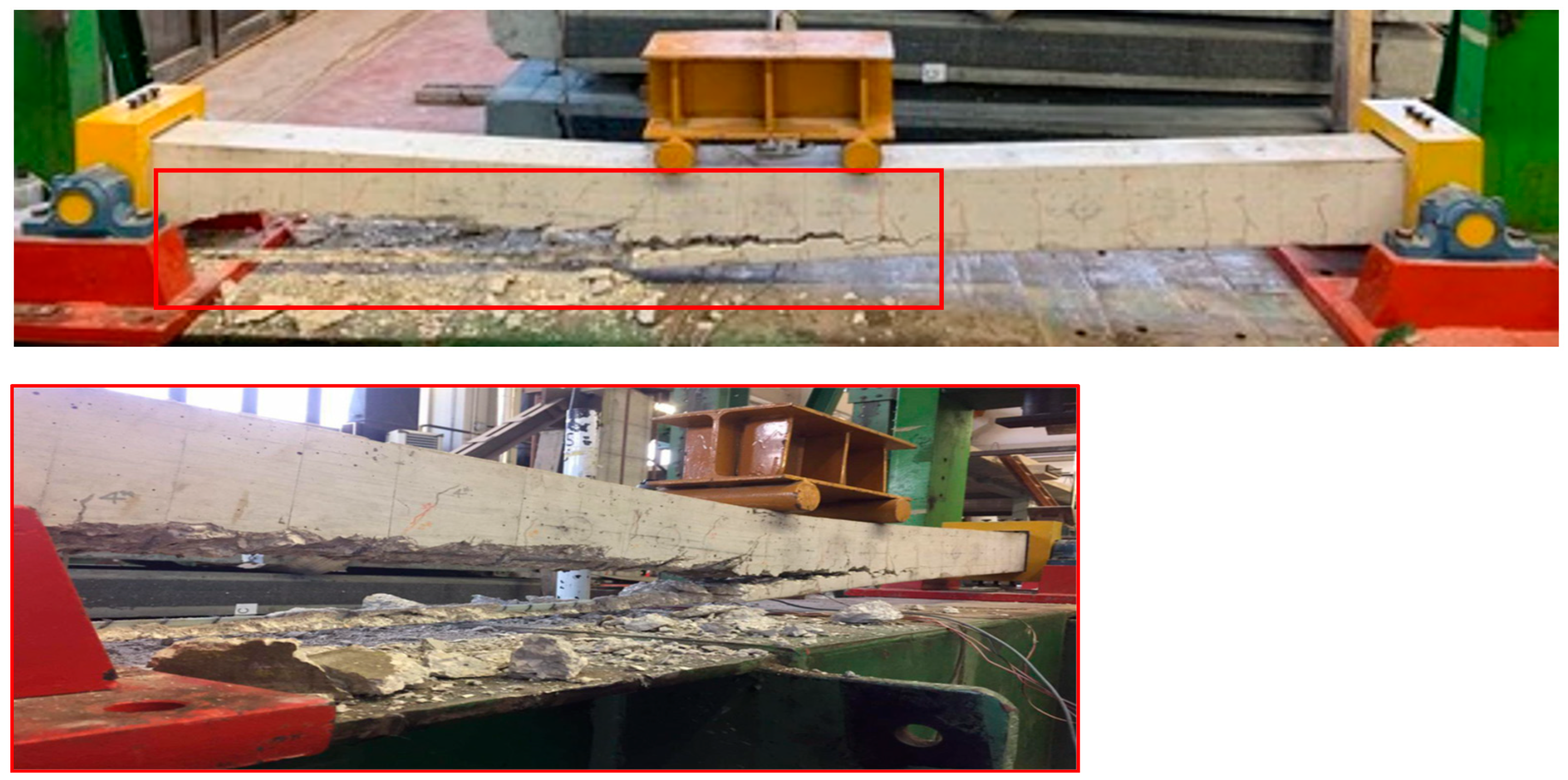
Figure 4 shows the failure mode of specimen B1
GFRP for a load value
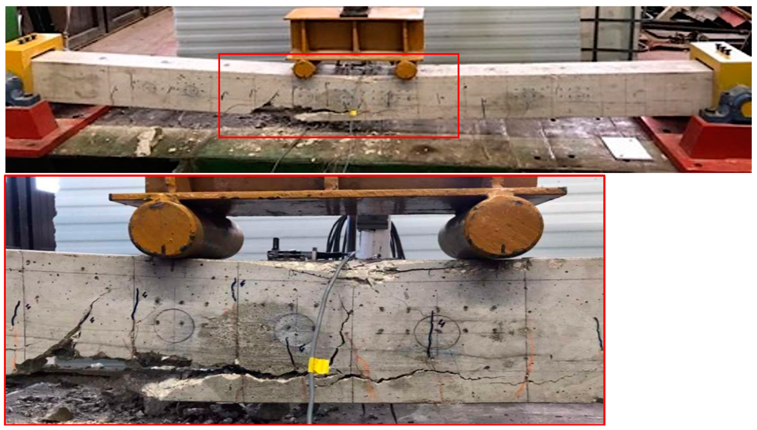
Pf higher than 38.40 kN, which affected the portion of the beam from the midspan section to the end section. It was observed that the failure was caused by the crushing of the compressed concrete and the complete debonding of the GFRP rod, causing the complete detachment of the concrete cover. The B2
CFRP specimen also showed a failure due to the crushing of compressed concrete and debonding of the CFRP rod, which started from the section with the maximum moment. In particular, the debonding between the adhesive and the surrounding concrete was recorded at the midspan; moving away from the midspan section, also part of the concrete cover, was affected (
Figure 5). In this case, debonding was limited close to the maximum moment region. The maximum load
Pf was equal to 49.06 kN.
As it emerges from
Figure 4 and
Figure 5, although failure loads for strengthening with CFRP and GFRP rods are different, the failure modes of the two strengthened beams are identical with the crashing of the compressed concrete and then the detachment of the concrete cover at the tensile side due to a high deformation level.
Dynamic tests were performed on RC beam models in parallel with the static tests, at the end of each
Di loading step, as a non-destructive testing method. In this way, the dynamic response of the experimental beam specimens, in terms of dynamic parameters (natural frequencies), is evaluated experimentally by checking the influence of strengthening and the effects of damage corresponding to the various loading steps. In the next paragraph, the general aspects of modal analysis will be discussed in detail. Vibration tests were performed on all RC specimens with free end conditions (
Figure 6). Dynamic response of those RC specimens, in terms of vibration frequencies, was recorded by installing an accelerometer in 9 different positions, Mark
i, with
i = 1, …9, along all experimental beams and generated the impulse using an instrumented hammer in a fixed position. The recorded frequency values are the average of 10 blows for each accelerometer position.
The free boundary condition was achieved by adopting suspension cables that acted as elastic springs with negligible rotational stiffness. To ensure a negligible interface of the suspension system on the constraint conditions of the beams, it was decided to position the springs as close as possible to the nodal points, i.e., at a distance of 100 mm from the ends of the RC beam specimens and 2.0 m between them.
The instrumentation adopted consists of an impact instrumented hammer, produced as Type 8202 Brüel & Kjær, whose impact point was fixed at 350 mm from one end of the beam models, and an accelerometer of the piezoelectric CCLD type produced by Brüel & Kjær brand n. 4508, which was instead moved during the dynamic tests to 9 different points, Marki with i = 1, …9. A random waveform exciter was used to cover the low-frequency range and linearize any nonlinear behavior. The marks positions have been chosen to avoid these coincided with the “modal nodes”, where the dynamic characteristics of the system are zero; therefore, the observability of the analysis is not guaranteed. Recorded frequency values are the average of 10 beats for every Marki.
The signals acquired by the accelerometer were processed and transformed in the frequency domain. To this end, the instrumentation also includes a Fast Fourier Transformation analyzer, a data acquisition system LAN XI TYPE 3050 Brüel & Kjær produced, managed by “BK CONNECT 2018–PULSE” software, developed by Brüel & Kjær company.
The RC beam models were tested after each load cycle,
Di, and related damage configuration, by means of 10 impacts with an instrumented hammer (
Figure 6), for each of the 9 measurement points where the accelerometer was placed, previously defined (Mark
i).
3. Experimental Main Results
Figure 7 provides information on the experimental trend of the total applied load,
P, compared to the average value of deflection,
δ, at beams midspan, where the vertical displacement transducer was placed. In each diagram, obtained experimentally on the RC beam un-strengthened model, B1 (
Figure 7a), and the models of RC beam strengthened, respectively, with GFRP NSM bar, B1
GFRP (
Figure 7b) and CFRP NSM bar, B2
CFRP (
Figure 7c), the experimental curves corresponding to each loading–unloading steps are reported.
The presence of FRP strengthening with the NSM technique leads to a significant increase in resistance compared to the initial configuration of the beam without strengthening, as the comparison between load–deflection curves of different RC beam models suggest; moreover, the presence of the NSM C/GFRP strengthening ensures the achievement of large deflection and, consequently, ductility that characterize the response of strengthened elements until failure condition. About the ultimate load capacity of the beam strengthened with CFRP bar, B2CFRP, it recorded an increase of about 22% compared to the B1GFRP. This is a direct result of the difference between the mechanical properties of the CFRP rod with respect to the GFRP one. If we compare the deflection values recorded for the first 3 load cycles, we can observe that specimen B2CFRP strengthened with CFRP rod shows a reduction of deflection of about 60% compared to specimen B1GFRP. Concerning the elastic phase, it can be noted that the stiffness of beam B2CFRP is higher than that of beam B1GFRP; this is once again due to the difference between the mechanical properties of the CFRP rod with respect to GFRP ones being Young’s modulus of GFRP is much lower than that of the CFRP, while the area of section is almost equal between CFRP and GFRP rods.
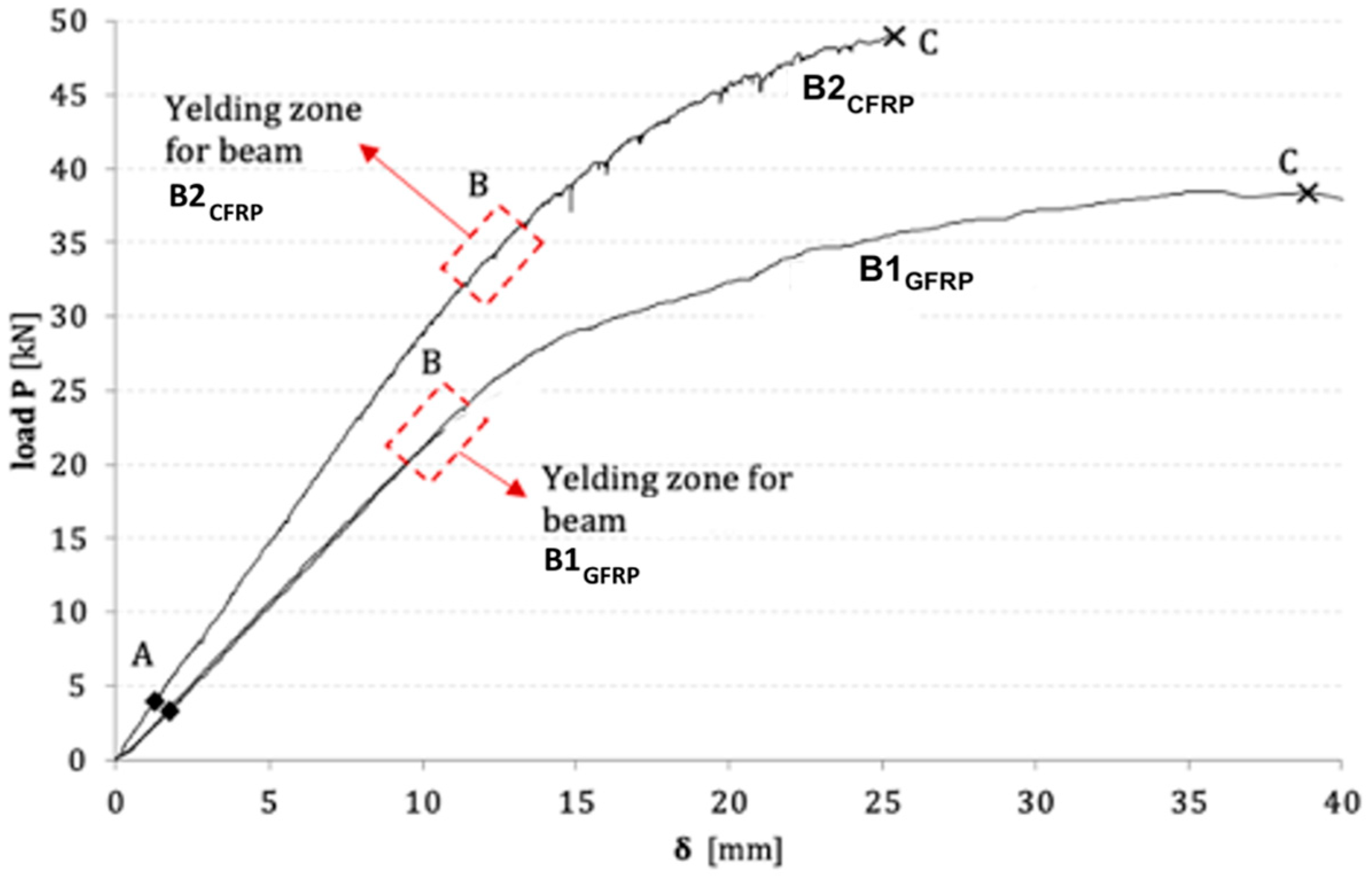
Experimental envelope of load,
P, versus midspan deflection,
δ, for strengthened RC beams B1
GFRP and B2
CFRP have been compared in
Figure 8. The changes in the slope of the load-deflection curves, resulting from the loading process, of the two strengthened RC beam models, highlight three distinct points, named A, B, and C, corresponding to the first cracking of the concrete, the yield steel strength, and the failure load, respectively. It is observed that the two curves are, therefore, characterized by three distinct parts: an elastic phase from point O to point A (O–A), a cracking phase of concrete (A–B), and the ultimate strength phase (B–C). It can be noted that the strengthening adopted in both cases improves the response of the beam with a higher load value for B2
CFRP, although B1
GFRP presents a higher ductility.
The results obtained from the experimental dynamic tests, using Frequency Response Functions (FRFs), are reported in 9 diagrams, corresponding to each position of the accelerometer. These diagrams contain the parameters that characterize the dynamic behavior of RC beam models.
Results of dynamic tests are analyzed and commented on below, considering the condition of the beam with free-free ends.
During vibration tests, a function referred to as coherence has been considered in order to obtain control over the results. So, for each of the measurements, it was checked that the value of the coherence was near one, which confirmed the quality of the results. The natural frequencies of four modes of vibration for each phase of increasing damage were then recorded, referring to condition D0 and the immediately preceding Di−1. In addition, the undamaged RC beam was also studied according to the Euler–Bernoulli theoretical model, which provides for a uniform, slender beam with negligible gravity forces, rotating inertia effect, shear deformation and damping. Theoretical results, in terms of frequencies, were, therefore, compared with the experimental ones.
Table 3 summarizes the main experimental results of the frequency values obtained at the various experimental load steps by free vibration analysis for all beam models, B1, B1
GFRP, and B2
CFRP, together with the frequency variations in percent
.
It can be observed that as the load and, therefore, the damage increased, a progressive reduction in the natural frequency value of the RC beam models was recorded. In particular, the un-strengthened beam model B1 is more sensitive to the decrease in frequency than the NSM-strengthened beams, in which it is less evident or absent.
4. Discussion
Using Euler–Bernoulli’s theory, the theoretical vibration frequency values of the un-damaged un-strengthened RC beam were calculated. Assuming a uniform and slender beam and neglecting gravity forces, the effect of rotary inertia, shear deformation, and damping for a beam in flexure, only the component of displacement
v is of interest, and
v is a function of position
x of the considered section and of time
t. The following equation is obtained for the free vibration of the beam [
48]:
where
is density of the material of the beam, and
A is the cross-sectional area.
The following formula allows us to calculate the theoretical flexural vibrations of Euler-Bernoulli’s beam for any constraint condition.
with
r = 1, 2, 3, 4. Multiplying the eigenvalue for the simply supported beam,
, by a coefficient
, which depends on the r-mode of vibration and the boundary conditions, the eigenvalue
relative to r-mode is determined for the beam with free–free ends;
The experimental results were also checked by a comparison of the data obtained by experimentation with the preliminary theoretical one given by FE modeling to limit possible errors of the dynamic response due to the imperfections of the experimental apparatus. The ANSYS code was adopted for FE modeling of the RC beam. The 3D model was created to reproduce the behavior of the undamaged beam considering the presence of all materials, including concrete, longitudinal steel reinforcements, and elastic suspension system or hinge conditions. The typical FE mesh of the undamaged beam B1 is shown in
Figure 9a. Concrete was modeled adopting a solid brick element labeled as Solid65 (
Figure 9b). Generally, concerning the modeling of steel reinforcement, it is possible to adopt three different strategies, namely the discrete model, the embedded model, and the smeared model. The presence of reinforcements is taken into consideration in the discrete model by using beam elements that are coupled to concrete mesh nodes. By increasing node numbers and degrees of freedom, the embedded model overcomes the concrete mesh constraints. Finally, the smeared model implies that reinforcement is evenly distributed over all concrete elements in a specified region. This approach is particularly useful for large-scale models where the overall response of the structure is not significantly influenced by the presence of reinforcement.
In this study, it was chosen to adopt the discrete model for the modeling of steel reinforcement with the use of the linear beam element with six degrees of freedom at each node, called Beam188 (
Figure 9b). As already described, the dynamic tests were performed based on free and hinge end conditions in vibration. The beams’ suspension springs were inserted in the numerical modelling in addition to the aforementioned elements with the aim to reproduce the beams’ suspension springs (
Figure 9b). The linear spring, labeled as element Combin14, defined by two nodes, a spring constant
k and damping coefficients, was adopted. The mass of the accelerometer was also taken into account in the model. The accelerometer was simplified as a point mass of 15 g. The first four natural frequencies of the beams that correspond to experimental modes measured from the tests were derived by modal analysis for each FE beam model hung by elastic springs (
Figure 10).
Table 4 contains theoretical frequency values using Euler–Bernoulli’s formula and the experimental average frequency values obtained for the B1 model beam in the un-damaged and un-strengthened condition
D0, as well as by finite element (FE) analysis for the first four vibration modes.
From the comparison between theoretical and experimental frequency values of beam B1, it is observed that the differences are not so significant, reaching similar values in particular for the first two modes of vibration, with an average deviation of less than 1%. The comparison between experimental, theoretical, and numerical data confirms the suitability of experimental apparatus for dynamic tests.
4.1. Comparison of Different Degrees of Damage
This section contains a comparison of the frequency values recorded for each RC beam specimen at the initial condition D0 with those in the subsequent load steps and damage phases. Frequency variations were defined to monitor the frequency trend as the damage increases.
Figure 11 shows the percentage change in frequency,
, based on the variation of the damage degree, of the first four vibration modes of each RC beam specimen.
The diagrams confirm that against the increase in crack damage, the frequency values responded to a decreasing trend; despite this, in some cases at the final load, higher vibration frequencies were recorded than those at the previous load steps, as in the case of the B2CFRP beam.
The B1
GFRP beam model, however, follows the opposite trend, with a frequency that increases slightly with the load level, as shown in
Figure 11b, where the trend of frequency values with the increase in damage state is almost imperceptible, especially for the first two modes. The first three vibration modes are characterized by negative percentage frequency variations compared to the initial state
D0
*; this trend is due to strengthening with NSM bars in the GFRP rod, limiting cracking damage by bending.
Figure 12 provides information on the percentage change in frequency as damage increases, compared to the previous one, calculated as
, for the first four modes of vibration. The diagrams (
Figure 12) show that the first two steps of bending load, corresponding to the beginning of concrete cracking, result in a significant decrease in frequency values. In the last load steps, however, the decrease in frequency values becomes modest until it records an opposite trend, i.e., an increase in values, as mentioned above. In addition, the most significant variation in frequency values is recorded for un-strengthened beam B1, which confirms how NSM strengthening can mitigate damage from bending cracking.
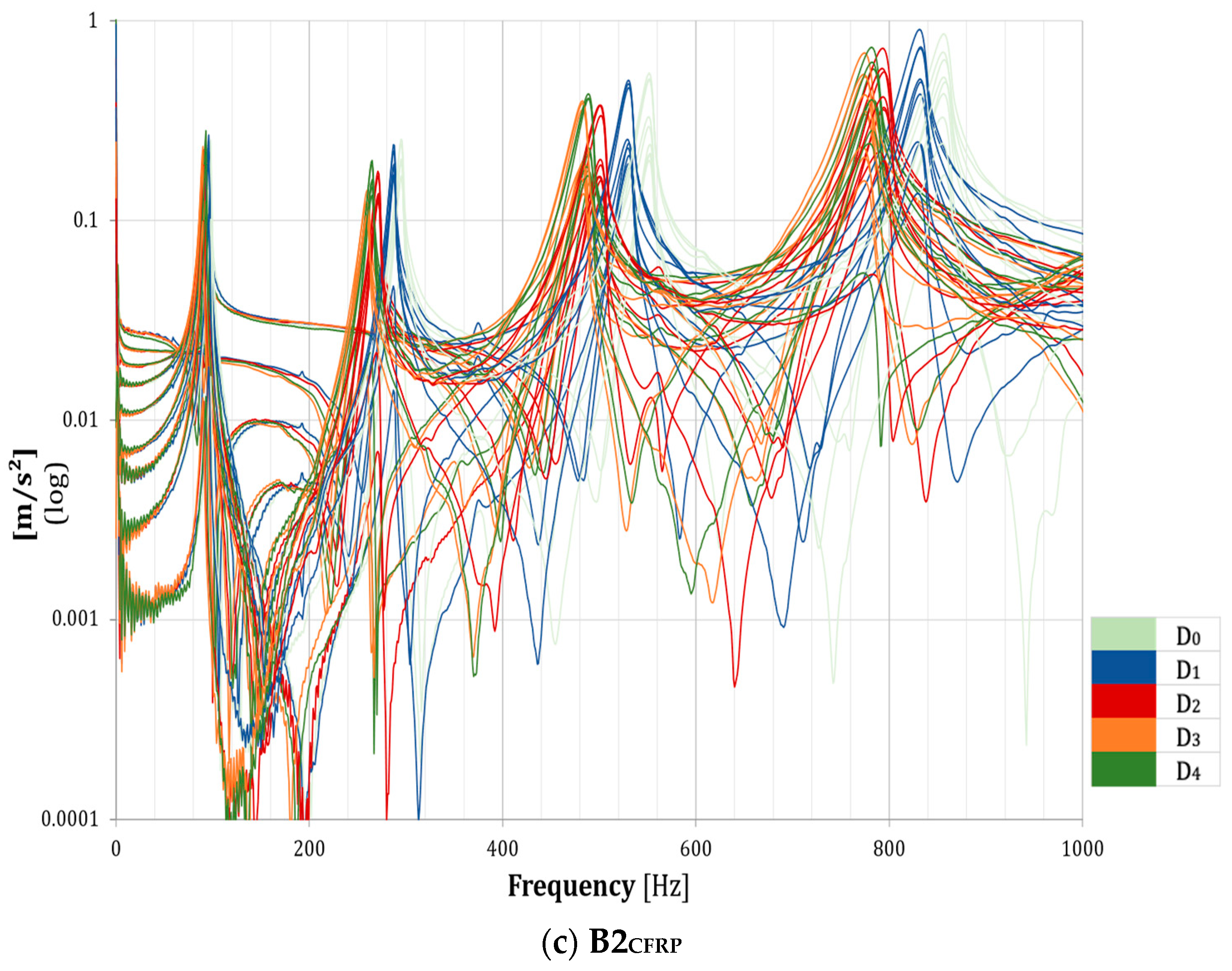
Finally, the FRF envelope diagrams for each RC beam specimen and each degree of damage are shown in
Figure 13. FRF envelopes show a clear shift of frequency peak values from right to left, with an increasing degree of damage, except for the B1
GFRP beam model, where the frequency peaks are almost completely overlapped.
4.2. Comparison of Types of Strengthening Materials
Once the percentage changes in frequency for each damage state have been compared, the comparison of the percentage changes in absolute frequency for the damage state
Di in relation to the initial condition
D0 (
Figure 14) and relative frequency to the damage state
Di+1 in relation to the previous damage condition
Di (
Figure 15) are shown. The aim is to evaluate the incidence of strengthening type in experimental RC beam specimens.
Examining the processed data, un-strengthened beam B1 underwent major absolute frequency variations; for the strengthened models, considering the first mode of vibration, the frequency variations are comparable between the model with GFRP and the one with CFRP; for the other vibration modes, specimen B1GFRP is the one that records the lower frequency variations. Regarding relative frequency variations, beam B1 is more influenced by the first cracking during the D2 load cycle; in this loading phase, the un-strengthened beam B1 registers the maximum frequency variations compared to the previous cycle. In B1GFRP and B2CFRP specimens, however, cracking appears to be delayed by one load cycle since there are higher variations during damage degree D2.
Results of modal testing confirm the effectiveness of the NSM technique for flexural strengthening of damaged RC beams, both with Glass-FRP and Carbon-FRP rods. By analyzing the modal parameters obtained experimentally in terms of frequencies, as shown in
Figure 16, it is possible to note a different effect of the two fibers on the dynamic response of damaged beams. For RC beams strengthened with NSM Glass-FRP, frequencies remain stable around the value that occurs for the level of damage prior to strengthening’s application (damage state
D3). As the level of damage increases, frequencies remain almost constant with low absolute frequency variations (less than 12%). In the case of the RC beam strengthened with NSM Carbon-FRP, a different behavior can be observed. Frequency values recorded after the application of the CFRP rod (damage state
D0*) are higher than the ones obtained before the strengthening application (damage state
D3). These values, although undergoing a decrease as the applied load increases, are always kept lower than the values recorded in the pre-strengthening condition.
This different behavior can be derived from the different mechanical properties between CFRP and GFRP strengthening rods: Young’s modulus of GFRP is much lower than that of CFRP, while the area of the section is almost equal.


