1. Introduction
As China’s urbanization accelerates, cement, the main building material, is currently consuming resources at an estimated rate of 2.1 billion tons per year. Along with this massive consumption of resources, China’s construction waste is growing by hundreds of millions of tons per year. It already accounts for 30~40% of total municipal waste, of which 50~60% is waste concrete. Compared to developed countries such as the US and the UK, the recycling rate of construction waste in China is less than 5% [
1]. Therefore, it is necessary to produce recycled concrete from construction waste that can be used in buildings, roads and other facilities in the cold regions of western China in order to conserve resources, improve the urban construction environment and develop a low-carbon and sustainable approach. However, as western China is a seasonally cold region, concrete structures are susceptible to the combined effects of freeze–thaw, salt erosion, carbonation and wind erosion. It is necessary to research the deterioration mechanism of recycled concrete under the coupled effects of freeze–thaw and salt erosion, and to improve the durability.
At present, a number of studies have been carried out on recycled concrete from different perspectives. Silva et al. point out [
2] that there is a partial decrease in the compressive strength of RAC in comparison with that of normal concrete. It was also found that as the rate of RAC replacement increased, compressive strength and modulus of elasticity were decreased [
3,
4]. Zhenxian [
5] concluded that the water–cement ratio was an important factor affecting the elastic modulus of RAC, which increased by 33.7% when the ratio was decreased from 0.8 to 0.4. Amnon and Katz [
6] were able to successfully formulate a high strength recycled concrete classified as C60. Alina and Andrze [
7] have found that the higher the strength class of the RAC, the faster the corresponding compressive strength is reduced in comparison to that of natural aggregate concrete. Some researchers have discovered that higher strength recycled concrete can be obtained by appropriate selection of constituents and admixtures and by pre-treatment of aggregates [
8,
9,
10,
11,
12]. Further, the addition of steel fibers can improve the strength and mechanical properties of the recycled concrete and retard the propagation of cracks [
13,
14,
15]. Some researchers have also reported that basalt fibers can increase the compressive strength and increase the crack resistance of concrete [
16,
17]. Mahmoud et al. [
18,
19,
20] demonstrated that both polypropylene fibers and basalt fibers can significantly improve the frost resistance of concrete.
Researchers [
8,
9,
10,
11,
12] have observed that the shrinkage rate of RAC is 30% to 50% higher than that of ordinary natural aggregate concrete, and Deakins [
21] pointed out that the durability factor of RAC is more than 95% at a substitution rate of 100%. As far as impermeability studies are concerned, Hansen and Jin [
22,
23] showed that the impermeability of RAC is lower than that of natural aggregate concrete and that it decreases as the substitution rate increases. When natural aggregates are replaced by recycled aggregates, the porosity within the concrete will increase, but the percentage increase in porosity will depend on the strength class of the concrete. There have also been various claims that RCA has a rougher surface, which is more adhesive than natural aggregates. Studies have shown that the treatment of recycled aggregate increases the bond strength of the mortar to the aggregate, with the most common treatments being chemical and polymer treatments [
12]. When it comes to resistance to salt attack, RCA concrete is almost as resistant to sulphate attack as concrete made from natural aggregates [
24,
25]. In addition, resistance to sulphate attack can be improved by appropriate use of silica fumes, fly ash, blast-furnace slags and fibrous materials. According to [
26,
27], the resistance of RCA concrete to alkali-silica reactions is dependent on the source of the recycled concrete aggregates. Researchers have reported that the expansion caused by alkali-silica reaction in recycled concrete can be significantly reduced by the use of low lime fly ash or silica fume [
28]. With regard to the resistance to freeze–thaw cycles, many researchers have noted that RCA concrete is sufficiently resistant to freeze–thaw cycles [
29,
30,
31]. Another study demonstrated this observation [
32]. In addition, freeze–thaw resistance is greater in concrete with a higher w/b ratio and higher RCA content. By altering the percentage change in weight, the w/b ratio can be altered to improve freeze–thaw resistance. However, a strong relationship between freeze–thaw loss and concrete can be observed [
30,
33].
While the above research results are informative for promotion and application of RCA, multi-scale research tools are lacking to study the deterioration mechanism of RCA under the coupled effect of freeze–thaw and salt erosion. In this paper, the recycled aggregates are obtained from the fragments of crushed concrete, and the defects of the recycled concrete are improved by the addition of steel and basalt fibers. The deterioration mechanism of the recycled concrete is revealed through salt freeze–thaw (5% sulphate solution) cycle tests by analyzing macroscopic indicators (mass loss rate, relative dynamic modulus loss and compressive strength change) and microscopic indicators (fiber distribution) in relation to basalt fiber content, steel fiber content and number of freeze–thaw cycles. Theoretical references for the promotion and application of fiber recycled concrete in cold regions can be derived from the research results.
3. Results and Discussion
The relative dynamic elastic modulus, mass loss rate and compressive strength loss rate of concrete are the main indicators for judging the concrete damage, and the variation rules of the three indicators are shown in
Figure 2,
Figure 3,
Figure 4,
Figure 5,
Figure 6 and
Figure 7.
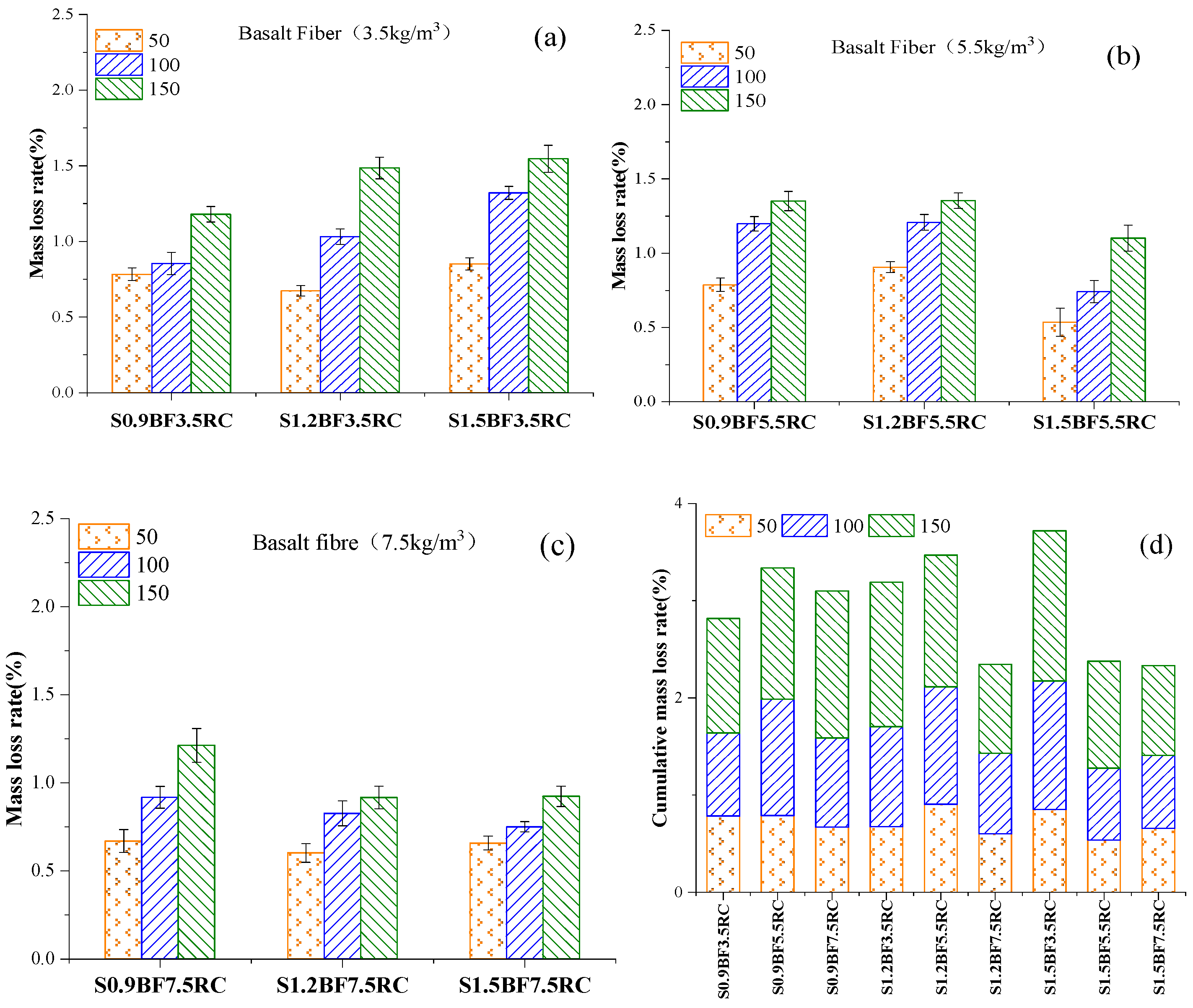
3.1. Mass Loss Rate
After 50, 100, and 150 freeze–thaw cycles,
Figure 2 and
Figure 3 show the mass loss rate of the specimens, which are NC, RC, steel fiber recycled concrete and basalt fiber recycled concrete, respectively.
Figure 2 displays the difference in mass loss among ordinary concrete, recycled concrete, single steel fiber recycled concrete and single basalt fiber recycled concrete.
Figure 2a demonstrates that the mass loss of ordinary concrete is less than that of recycled concrete during the whole freeze–thaw cycle. During the whole freeze–thaw cycles (50, 100 and 150 freeze–thaw cycles), it can be presented from
Figure 2b that the mass loss rate of S
0.9RC is the lowest among all single steel fiber recycled concretes, which is 2.11%. Compared with recycled concrete, the accumulated mass loss of S
0.9RC during the whole freeze–thaw cycles (50, 100 and 150) decreased by 2.39%. It can be concluded from
Figure 2 that the single basalt–steel fiber can decrease the mass loss of recycled concrete to some extent. As can be seen from the figure, the loss of mass of BF
5.5RC and BF3.5RC is less than that of BF7.5RC for the recycled concrete with a single basalt fiber. The reason for this may be due to the higher content of basalt fibers in BF
7.5RC, where there are more exposed parts and more defects on the surface of the specimen than in BF
3.5RC and BF
5.5RC. After 150 freeze–thaw cycles, the mass loss of the specimens is higher because the surface defects are first destroyed by the freeze–thaw action.
Figure 3a–c shows that the mass loss rate increases with the number of freeze–thaw cycles and decreases with increasing fiber amount.
Figure 3a shows that the mass loss rate of S
0.9BF
3.5 is lower than that of S
1.2BF
3.5RC, with a cumulative mass loss rate of S
0.9BF
3.5RC of 2.82%. The cumulative mass loss value of S
1.5BF
7.5RC is the lowest in all specimens of basalt fiber–steel fiber recycled concrete with 2.33%, as shown in
Figure 3d. The main reason may be that steel fiber and basalt fiber make recycled concrete less prone to spalling because fiber can increase internal stress and prevent the expansion of cracks [
34].
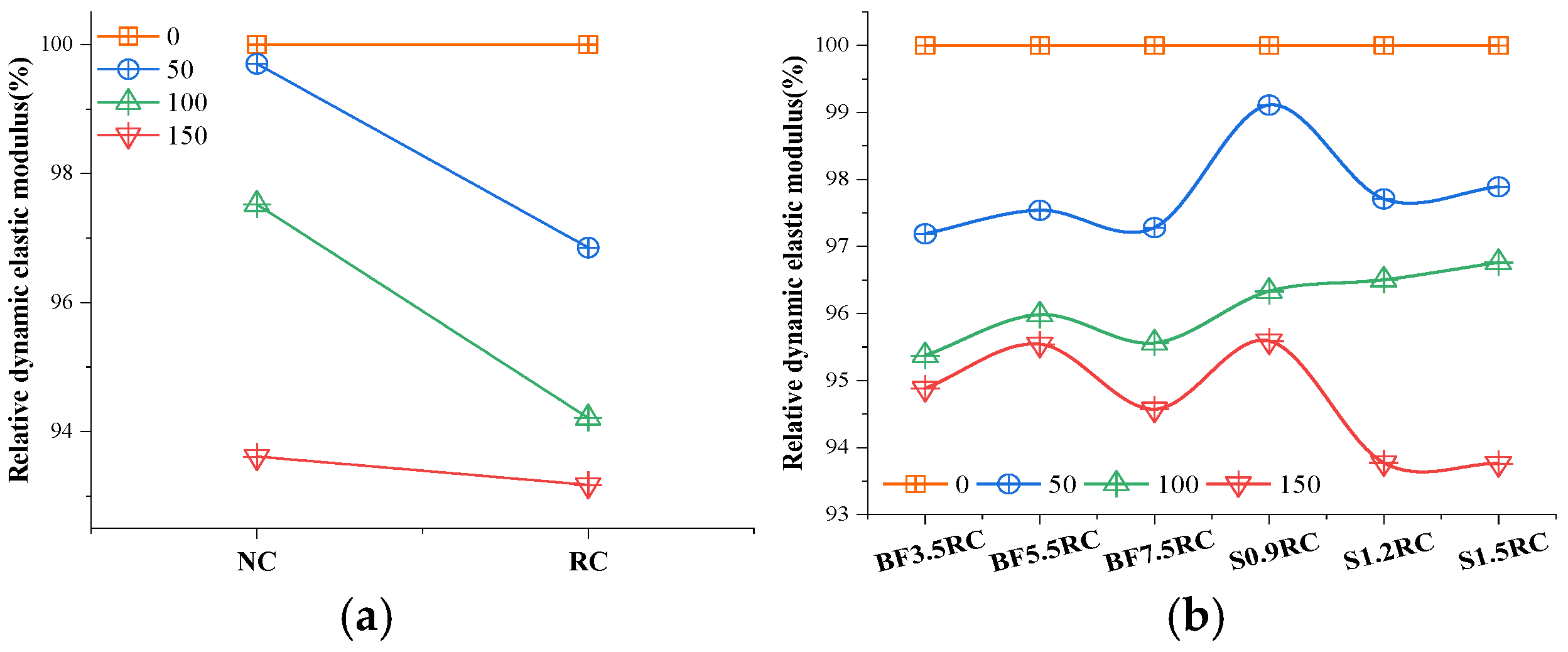
3.2. Relative Dynamic Modulus of Elasticity
During the whole freeze–thaw cycle, a comparison of the relative dynamic elastic modulus from NC to S
1.5RC is shown in
Figure 4.
It can be seen from
Figure 4a that the relative dynamic elastic modulus of recycled concrete decreases significantly during the freeze–thaw cycle. As the number of freeze–thaw cycles increases, the relative dynamic elastic moduli of all the specimens mentioned above decrease significantly, as shown in
Figure 4. The smallest relative dynamic elastic modulus loss is S
0.9RC at 150 freeze–thaw cycles in the series of fiber-only recycled concrete. Compared with RC, the relative dynamic modulus of S
0.9RC increases by 2.42%. This result indicates that adding fiber to recycled concrete improves the dynamic elastic modulus to some extent.
The relative dynamic modulus of S
1.5BF
3.5RC is higher than other specimens at 150 freeze–thaw cycles, as shown in
Figure 5a. Compared with S
1.5BF
3.5RC, the relative dynamic elastic modulus of S
1.5BF
5.5RC increased by 0.01% seen in
Figure 5b, while the S
1.5BF
7.5RC increased by 0.14% displayed in
Figure 5c. It is concluded that the specimen of S
1.5BF
7.5RC has good compactness. The relative dynamic elastic modulus of all the specimens decreases during the whole freeze–thaw cycle due to the sulfate attack phenomenon and expansion stress inside the test block. On the one hand, appropriate amounts of steel fibers and basalt fibers can effectively inhibit the generation and development of concrete microcracks; on the other hand, it can refine the coarse pore structure, reduce the total porosity and harmful porosity, and improve the bonding ability of the aggregate and the cement matrix [
35,
36].
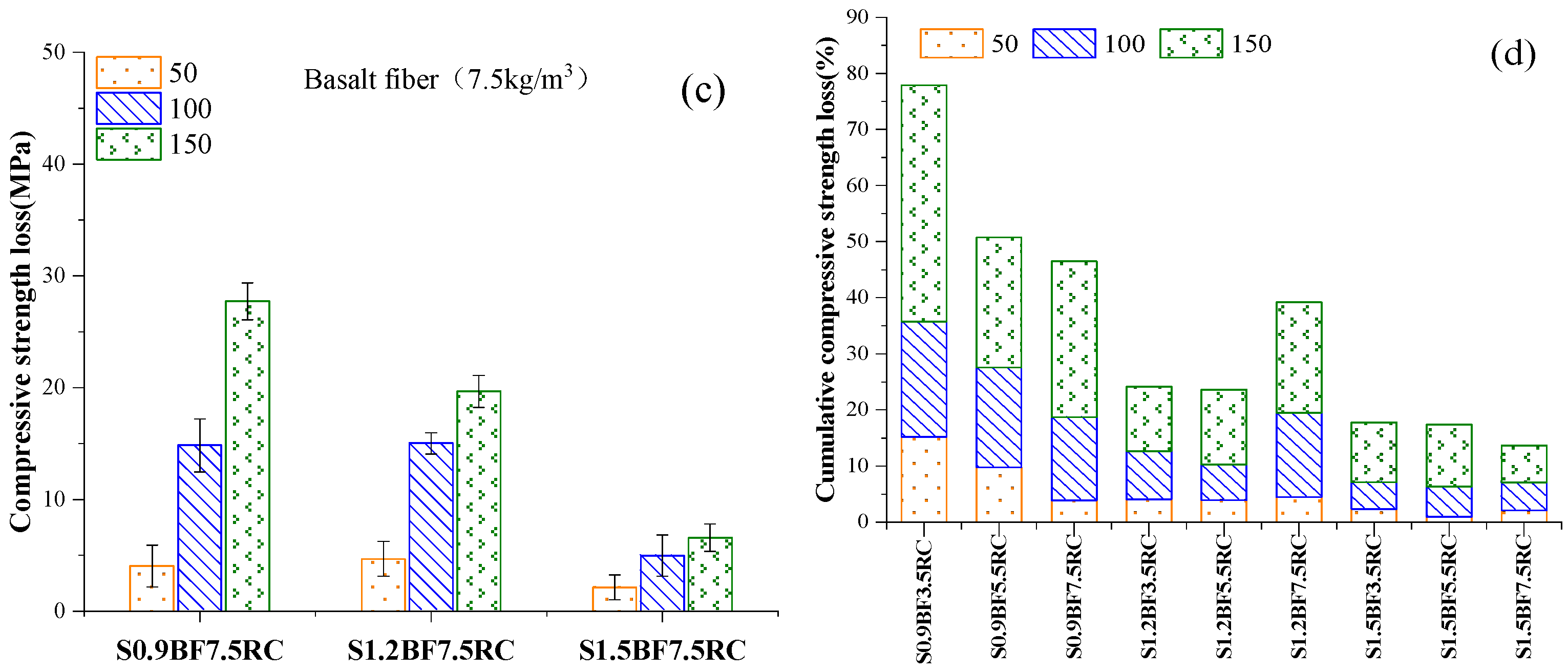
3.3. Compressive Strength of Concrete Mixed with Steel Fiber and Basalt Fiber
Figure 6 shows that the compressive strength of the specimens decreases with the increase in freeze–thaw cycles. It can be seen from
Figure 6a that the compressive strength of RC is lower than that of NC during the whole freeze–thaw cycle. The compressive strength of S
0.9RC is higher than that of other specimens at the same freeze–thaw cycle, which is 65.9 MPa, 64.2 MPa, 61.1 MPa, and 50.9 MPa, respectively, as shown in
Figure 6b. The reason may be that the steel fiber mainly played an essential role in enhancing compressive strength [
37]. Nevertheless, appropriate steel fiber proportion contributes to the compressive strength of recycled concrete, while excess steel fiber weakens it. It can be seen from
Figure 6b that the compressive strength of S
1.5RC decreases with more steel than S
0.9RC and S
1.2RC. The excessive content of steel fibers, which tend to cause agglomeration, may be the reason for this phenomenon.
S
1.5BF
3.5RC has a higher compressive strength than S
0.9BF
3.5RC and S
1.2BF
3.5RC at 150 freeze–thaw cycles, as shown in
Figure 7a. Compared with S
1.5BF
3.5RC, the compressive strength of S
1.5BF
5.5RC increases by 0.65%, 2.04%, 0.05%, and 0.18%, respectively, while the S
1.5BF
7.5RC improves by 1.96%, 2.21%, 1.77% and 6.59%, respectively, as demonstrated in
Figure 7c. It can be seen from
Figure 7d that the highest cumulative compressive strength is S
1.5BF
7.5RC up to 240.7MPa. The main reasons may be the internal pore structure improved by the incorporation of steel fiber and basalt fiber and the bonding force between the fiber and the matrix. Compared with the compressive strength of S
0.9RC, it can be found that the overall compressive strength of S
1.5BF
7.5RC is better. The main reason may be that the toughness under compression increases with fiber content [
38,
39,
40].
Figure 8 demonstrates the change in compressive strength rate during the freeze–thaw cycle. The compressive strength loss rate creases at 150 freeze–thaw cycles, displayed in
Figure 8a, which shows that the anti-freezing ability drops sharply at this time. It can be seen from
Figure 8b that the compressive strength loss rate of the specimens added with fibers decreased to varying degrees at 150 freeze–thaw cycles. Compared with the RC compressive strength loss rate of 20.52%, BF
7.5RC is 20.00%, which is the smallest compressive strength loss rate among all specimens.
It can be seen from
Figure 9 that the compressive strength loss rate decreases as the dosage of basalt fiber and steel fiber increases. When the BF content is 3.5 kg/m
3 (
Figure 9a), the compressive strength loss rate of S
1.5BF
3.5RC decreased by 6.82%, 9.51%, and 29.88% compared to RC during whole freeze–thaw cycles (50, 100 and 150 freeze–thaw cycles). As the BF content increases to 5.5 kg/m
3 (
Figure 9b), the strength loss rate value of S
1.5BF
5.5RC is reduced. When the BF content is 7.5 kg/m
3 (
Figure 9c), the S
1.5BF
7.5RC is the same as S
1.5BF
5.5RC. The reason may be that the addition of basalt fiber can improve the bonding force between the steel fiber and the recycled aggregate, which makes the aggregate unseparated from the cement base. Moreover, the hybrid fiber can lower the expansion stress generated inside the concrete, improve the integrity of the concrete, and reduce the loss of strength [
13,
41,
42].
3.4. Detailed Analysis
Figure 10 illustrates how the internal structure of NC and RC concrete behaves. It can be visualized from the figures that there are more NC visible aggregates than RC. This may be due to the fact that the recycled aggregate was obtained from laboratory high-strength concrete that had been mechanically crushed. The mechanical crushing process transforms the concrete from large pieces into smaller pieces with a large number of hairline fractures at the edges of the smaller pieces. Their addition to the concrete, based on the coupling of freeze–thaw cycles and sulphate, makes the concrete matrix in the RC less monolithic and eventually causes a dramatic decrease in the compressive strength of the concrete.
Figure 11 demonstrates the internal structure of the single admixture concrete. From
Figure 11a, it can be seen that the single admixture BF does not visualize its corresponding classified structural situation so it was specifically analyzed in the subsequent SEM experiments. As can be seen in
Figure 11b, at this point, the S content is lower and therefore more loosely distributed and less prone to agglomeration. The macroscopic data reveal that the overall frost resistance of the concrete decreases as the S content of the single admixture increases, probably because the single admixture of steel fibers is not suitable for uniform dispersion during the mixing process of production, and increasing its admixture equates to increasing its weakness. This phenomenon indicates that steel fibers have some synergistic effect with basalt fibers.
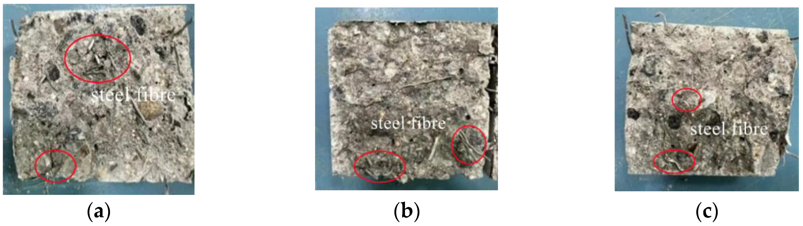
Figure 12 revealed the manifestation pattern of the internal structure of S–BF–RC concrete. It can be visually seen from the figure that the S distribution is more loosely distributed and agglomeration improves significantly with increasing BF admixture under constant S admixture conditions. The reason for this is probably due to the nature of the steel fibers themselves, which makes it possible to effectively increase the compressive strength of the recycled concrete and the fact that the steel fibers are therefore not so easily dispersed evenly during the concrete mixing process. The addition of basalt fibers makes it easier to disperse the fibers evenly during the mixing process due to the different nature of the two fibers, decreasing the formation of agglomerates. This counteracts the expansion of the ice crystals during the freeze–thaw cycle, as well as the increased support of the concrete by the steel fibers during the compressive process; the basalt fibers improve its toughness and the two fibers themselves are independent of the freeze–thaw environment, thus together boosting the compressive strength of the recycled concrete.
3.5. Microanalysis
(1) From the above, it can be concluded that the compressive strength of recycled concrete is lower than that of ordinary concrete under different numbers of freeze–thaw cycles. In order to better analyze the reasons for strength loss, the micro-level factors were further explored by scanning electron microscopy.
Figure 13 presents SEM images of ordinary concrete and recycled concrete at the end of a 28 d curing. As can be seen from
Figure 13, ordinary concrete, under the condition of not experiencing freeze–thaw cycles, has a strong bond between the cement paste and the aggregate, with structural integrity and good state of hydration products, as shown in
Figure 13a,b. However, the recycled concrete, under the same conditions, has relatively loose bonds between the cement paste and the recycled aggregate and the structure is not sufficiently complete, as illustrated in
Figure 13c,d. By comparing
Figure 13a with
Figure 13c, it is evident that without freeze–thaw cycles, the recycled aggregate has developed fine cracks, which are not penetrated and have a lesser effect on the compressive strength. Under the action of freeze–thaw cycles, the original cracks within the concrete become continuously larger as a result of the expansion force of the ice crystals, thus causing the internal structure of the concrete to be destroyed. For this reason, the compressive strength gradually decreases as the number of freeze–thaw cycles increases.
(2) The macroscopic data analysis indicated that the basalt fibers optimized the compressive strength of the recycled concrete under different numbers of freeze–thaw cycles, among which BF7.5 had the most significant effect. To better explain the reasons for this, the micro-level factors were further explored by SEM methods.
Figure 14 presents SEM images of concrete with a BF dosage of 5.5 kg/m
3 under 0 freeze–thaw cycles. It can be seen from
Figure 14a that the basalt fibers are fracture damaged in compression, rather than pull-out damage. This means that basalt fibers act as a barrier to the expansion of microcracks within the matrix and a deterrent to the occurrence and development of macro-cracks through molecular adsorption between the surface of the cement paste and the cementitious forces between the matrix. Therefore, increasing the dosage of BF can increase compressive strength.
Figure 14a demonstrates that the fibers are mostly concentrated in one direction within the concrete matrix with low fiber spacing and low dispersion. When the BF admixture is increased to 7.5 kg/m
3, the excessive fibers incorporated into the concrete increase the chance of fiber overlap, agglomeration and overlap, increasing the number of weak links within the concrete. This may consequently lead to a significant decrease in the mechanical properties of the concrete, as shown in
Figure 14b.
3.6. Salt-Freeze Coupling Mechanism
Freeze–thaw deterioration of S–BF composite fiber recycled concrete based on a sulphate environment is shown in
Figure 15. In this paper, the deterioration is divided into pre-freeze, continuous freezing phase and thawing phase.
Pre-freeze. The concrete is in a sulphate environment. The sulphate solution under the dual action of osmotic pressure and freezing force slowly started to penetrate from the microcracks and linked capillary pores of the concrete to the interior concrete, as shown in
Figure 15a. At the same time, the sulphate solution also started to move from the connected capillary pores to the interior of the concrete. This causes the sulphate solution within the microcracks to move more rapidly as the air in the pores inside the concrete contracts at the onset of freezing until the microcracks and capillary pore channels in the concrete are filled with the salt solution. The rate of penetration for the sulphate solution was related to the complexity of the distribution pores and microcracks within the concrete. The sulphate lowers the ice point of water, which also increased the time for the sulphate to move into the concrete interior. During the movement of sulphate toward the interior of the concrete, sulphate ions interact with cement hydration products in the microcracks or capillary pores to produce expansive substances, such as gypsum and calcium alumina. The more sulphate solution there was, the more saturated the solution was in the microcracks and capillary pores, and the more expansive substance content was generated.
Continuous frozen stage. At this stage, the sulphate solution had reached its frozen point. Since the test equipment simulated the freeze–thaw environment in the western cold region, the frozen phenomenon was carried out from the outside to the inside, so the capillary pores and microcracks on the concrete surface would freeze first, and then the ice crystals gradually grew the capillary pores and microcracks inside, and also blocked the passage for the sulphate solution to proceed inside the concrete. At this point, the concrete interior was coexisting with the sulphate solution, air and ice crystals, as shown in
Figure 15b. As a result of the freeze concentration principle, part of the water in the sulphate solution was frozen, which caused the sulphate solution concentration to reach saturation after the sulphate was precipitated and attached to the crack or pore wall. The existence of freezing stresses between the ice crystals and the solution would force the sulphate solution to move continuously towards the interior of the concrete until the sulphate solution was completely frozen under the effect of the temperature field. The frozen phenomenon leads to an increase in the volume of the ice crystals, which generates freezing stresses on the microcracks or pore walls, further extending the microcracks. The pores generate high internal stresses due to the continued generation of swellings and salt resulting in cracks within the concrete and accelerated expansion over time, illustrated in
Figure 15c. However, some of the freezing and swelling stresses were transferred to the fibers because of the presence of steel and basalt fibers in the recycled concrete.
The melt stage. During this stage, the temperature in the pores or cracks was lower than the surface of the concrete and melting proceeded from the surface ice crystals to the interior. As ice crystals in the pores or microcracks on the surface of the concrete melt, the internal pores keep the solution moving outwards as there is freezing stress; the melting temperature rises until the ice crystals completely dissolve and the solution would continue to move outwards, migrating swelling materials such as gypsum and calcium alumina in the process.
In summary, the mechanism of freeze–thaw deterioration of the specimens when the recycled concrete is exposed to sulphate was as follows. Firstly, the sulphate reduced the icing point of the water and increased the time for the sulphate solution to enter the interior of the recycled concrete. It also increased the content of sulphate solution inside the recycled concrete. Secondly, the expansion stresses generated by the expansive material generated in the sulphate solution entering the recycled concrete are weakened by the presence of steel and basalt fibers. The freeze stresses generated due to the decreased ice point were also weakened by the presence of the fibers. Finally, the stresses on the pore walls or cracks resulting from the continuous precipitation of sulphate during the migration of the sulphate solution adhering to the pore wall or crack interface were also weakened by the fibers.
4. Conclusions
In a sulphate attack environment, the incorporation of basalt and steel fibers into recycled concrete has a significant improvement on the expansion of internal pores and cracks. Additionally, the following results displayed in this paper may be limited to the specimens used in this research.
(1) Throughout the freeze–thaw cycle, cumulative spalling of BF5.5 was 3.25% and compared to natural aggregate concrete, compressive strength was increased by 27.36% for BF5.5RC and 32.90% for S0.9RC. The relative dynamic modulus of elasticity of S0.9RC was increased by 1.98%. The test results indicate that the poor freeze resistance of the recycled concrete exposed to the sulphate environment can be compensated for by the basalt and steel fibers. After 150 freeze–thaw cycles, the compressive strength of the S1.5BF7.5RC composite fibers was increased by 42.80% and the cumulative loss of mass was reduced by 43.39% in comparison with the ordinary concrete. Incorporating basalt fibers and steel fibers together in recycled concrete can increase basalt fiber incorporation and decrease fiber agglomeration.
(2) In a freeze–thaw cycle, the sulfate solution attacks the recycled concrete by freezing from the outside to the inside, the ice crystals extend along the cracks to the inside of the matrix, and the pore wall pressure contributes to the expansion and development of the cracks. Air and brine in the pores contract during freezing, creating a negative pressure that attracts external brine inwards. As the concrete continues to cool, ice crystals and unfrozen solution coexist. When the salt solution heats up and melts, the residual freezing pressure and the temperature difference between the inside and outside forces it to move outwards. The sulphate lowers the freezing point of the concrete and the diffusion behavior of the sulphate ions, resulting in increased liquid uptake by the concrete and an excess of aqueous solution that exacerbates the freeze–thaw damage. Concrete freezes in layers due to the high external and low internal concentration of the salt solution.
(3) In composite fiber recycled concrete, the expansion stresses generated by the sulphate solution during migration are also weakened due to the presence of steel and basalt fibers; the freezing stresses generated by the reduced freezing point of the salt solution are also weakened by the presence of the fibers; and the stresses on the pore wall or fracture are also weakened by the presence of the fibers. Such stresses are generated by the continuous precipitation of sulphate from the sulphate solution as it migrates and thus adheres to the pore wall or fracture interface.


