Article

Investigation of Corrosion Effects on Collapse of Truss Structures

by
Zeynep Fırat Alemdar
*,† and
Fatih Alemdar
Department of Civil Engineering, Yıldız Technical University, Istanbul 34220, Turkey
*
Author to whom correspondence should be addressed.
These authors contributed equally to this paper.
Buildings 2023, 13(3), 826; https://doi.org/10.3390/buildings13030826
Submission received: 15 February 2023 / Revised: 12 March 2023 / Accepted: 20 March 2023 / Published: 22 March 2023
(This article belongs to the Special Issue Performance Evaluation and Improvement of Corroded Steel Structures)

Abstract

:
Corrosion damage is a serious problem in steel structures. The cross-sectional loss in the structural members due to corrosion reduces the load-carrying capacity of the members and the stability of their structures. In this study, the main reasons for the collapse of three steel sports infrastructure facilities after moderate snowfall were investigated by conducting field observations and detailed numerical analyses. Finite element models of the structures were developed by considering the effects of different rafter systems and corrosion damage at their columns’ support regions. The load-carrying capacity ratios and stress distributions of the structural members were determined under the effect of the snow load at the time of the collapse. The analysis results were consistent with the damage modes observed during site inspections. The snowfall was not the primary cause of the collapse; however, the section and joint losses due to excessive corrosion, improper erections, and discrepancies between the design project and the as-built project were the main reasons for the collapse.

1. Introduction

An inadequacy of professional design and construction experience, poor communication between the engineers and their supervisors, the complication caused by codes and specifications, and unexpected extreme loads can lead to structural failures. These types of failures or even devastating collapses are observed globally in structures with steel roof systems, such as exhibition centers, airport terminals, industrial halls, and sports centers [1,2,3,4,5,6]. These sudden collapses mostly occur due to deficiencies in the planning of maintenance interventions. Research studies indicate the importance of the appropriate maintenance of these steel constructions. Corrosion in steel members can be detected during adequate interventions, and the collapse of their structures may be prevented under both service conditions and extreme loads.
Corrosion performance levels of structural steel materials were investigated using different precorrosion methods [7,8,9,10,11]. Existing experimental studies on the tensile strength and ductility of steel materials showed that corrosion greatly reduces the mechanical properties of steel. Czarnecki and Nowak [12] realized that corrosion at connections can be more important than in beam and column members. This could be because the connection plates and bolts often have different material characteristics with distinct corrosion resistance levels [13]. Connection failures can happen unexpectedly, even if the applied load is smaller than the tensile strength of the steel material [14]. Li et al. [15] showed that the capacity of joints should be evaluated under the effect of both fatigue and corrosion to prevent sudden collapses. A model was developed to define the influence of corrosion on the stress–life (S–N) curve of corroded steel. It was determined that neglecting corrosion’s effect reduces the possibility of fatigue collapse of corroded joints over more than 150 years by 15.45%. In addition, the corrosion rate had a significant effect on the probability of fatigue failure due to corroded joints in the long-term [15].
Corrosion creates geometric changes in steel connections and has an influence on their stress range under load cycles [16]. Adasooriya and Siriwardane [17] further investigated the fatigue strength state of connections under corrosion. The S–N curves of steel connections with different corrosion levels were determined in recent research studies [17]. Zampieri et al. [18] and Rodriguez et al. [19] determined that the stress range in corroded connections was less than the stress range for uncorroded connections in the number of load cycles up to collapse. Corrosion contributes to the decreases in the fatigue life of connections and to crack initiation [20]. Experimental studies on fatigue crack growth for corroded joints show that corrosion can influence the growth rate of cracks [21].
The aim of this study was to determine the root causes of the collapses of three steel structures after moderate snowfall. The structures were investigated by conducting visual inspections and detailed numerical simulations. The modifications in the support conditions caused by the excessive corrosion, especially in the truss column support regions, were taken into account in the numerical analyses. The effect of different rafter systems on the force distribution of the structures was investigated. The main reasons for the collapses are identified as different roof rafter systems in the structures, section and contact losses due to excessive corrosion, improper manufacturing, and inconsistency between the designed project and the as-built project due to a lack of building inspection control during erection.

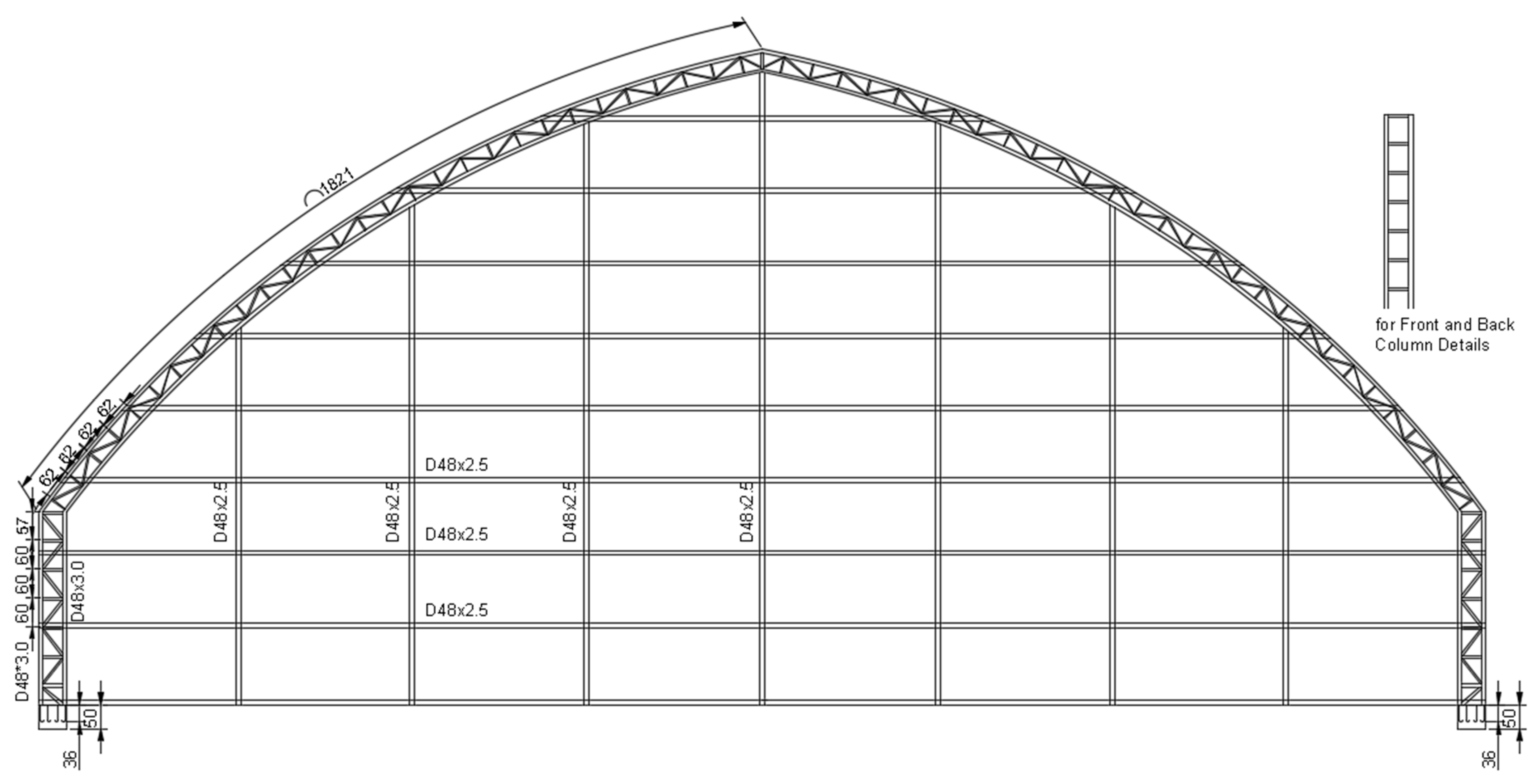
2. General Information about the Structures

The steel structures under investigation were operated as indoor sports fields and are located in Istanbul, Turkey. The structures had an altitude of approximately 80 m above sea level. The static projects of the structures were missing; only a shop drawing was obtained, and the sectional view of the structure was redrawn, as given in Figure 1. The three steel structures had the same steel members and dimensions. In the shop drawing, only the general dimensions of the systems were given, and there were no details on the connections. The shop drawing was compared to the as-built project during site investigations. Because the on-site measurements were taken from collapsed and structures that were dangerous to walk in, only the dimensions and locations of the structural members were considered to identify the differences. The measurements were in accordance with the dimensions in the drawing; however, there were some structural discrepancies between the drawing and the built structure.
The plan dimensions of the structure in the shop drawing were 30 m × 50 m for the collapsed structures. The load-carrying system of the structures consisted of open-web curved rafters with truss columns and steel purlins. The system was constructed at 3 m intervals. The roof had a span of 30 m, and the height difference between the eave line and top of the roof was 9.56 m. The angle of the roof with respect to the horizontal axis varied from 52 to 13 degrees linearly. The height of the truss column was 4.00 m. The cross-sectional dimensions of the structural members were obtained from the original drawing in Figure 1. Regarding the roof system, the open-web curved rafter system was made of circular sections of D76.1 × 2.5 mm at the top and bottom chords and sections of D46.3 × 2.5 mm for diagonal and vertical elements. The steel truss columns had cross-sections of D88.9 × 3.0 mm for the vertical elements and D46.3 × 2.5 for the diagonal and horizontal members. The steel purlins were circular sections of D46.3 × 2.5 mm that repeated at an interval of 0.6 m.
On the roof plane and along the façades, brace elements were observed in on-site investigations of wind stability; however, they were not found in the shop drawing. These structural elements were generally formed with D42.4 × 2.5 mm circular sections and connected to the truss column members and roof rafters with site welding.
In the on-site examinations, it was observed that the purlins were joined to the rafter systems as well as to each other via fillet welding. The weld sizes were determined as the minimum for each profile based on the thicknesses of the profiles. There were some differences in the configurations of the diagonal and vertical elements used in the rafter systems in one structure, as shown in Figure 2. Numerical simulations were defined individually to consider the differences in the rafters.
The column support plates were supposed to be connected to the ground with six anchor rods as given in the shop drawing, whereas two reinforcing steel bars were only welded by bending to the support plates in the as-built project.
The mechanical properties of the steel material were obtained by performing tensile coupon tests in accordance with ASTM E8 [22] because there was no information on material strength in the project drawings. The measured average yield strength, ultimate tensile strength, and Young’s modulus were calculated as 269 MPa, 467 MPa, and 201,000 MPa, respectively.

3. Evaluation of Roof Snow Load

The structures were exposed to 23–25 kg/m2 snowfall in the period of 25–26 January 2022, according to the report received from the Meteorology Directorate during the dates of the collapses. The design snow load was calculated based on European Standard 1991-1-3 (as national standard, TS EN 1991-1-3) [23]. The snow load on ground, Sk, was taken as a similar value, which was obtained according to TS 498 [24]. The design ground snow load was defined as 75 kg/m2, as defined in TS EN 1991-1-3. The topographic conditions of the region were assumed to be normal; thus, the recommended values given in TS EN 1991-1-3 for exposure coefficient, Ce, and thermal coefficient, Ct, were set to 1.0. The roof pitch angle was variable and less than 60° for the collapsed structures; thus, the snow load shape coefficient, μ3, was defined as 0.8. The design roof snow load value was then calculated to be 60 kg/m2 based on the given parameters. The roof snow load value was computed to be 20 kg/m2, according to the meteorological report. This snow load value was less than the design’s snow load value taken in the project. Therefore, it was expected that the smaller snow load acting on the roof will not cause the collapse of the structure. Furthermore, it was revealed that possible errors in the design or construction phases of the structures and damage related to corrosion may have led to their collapses.

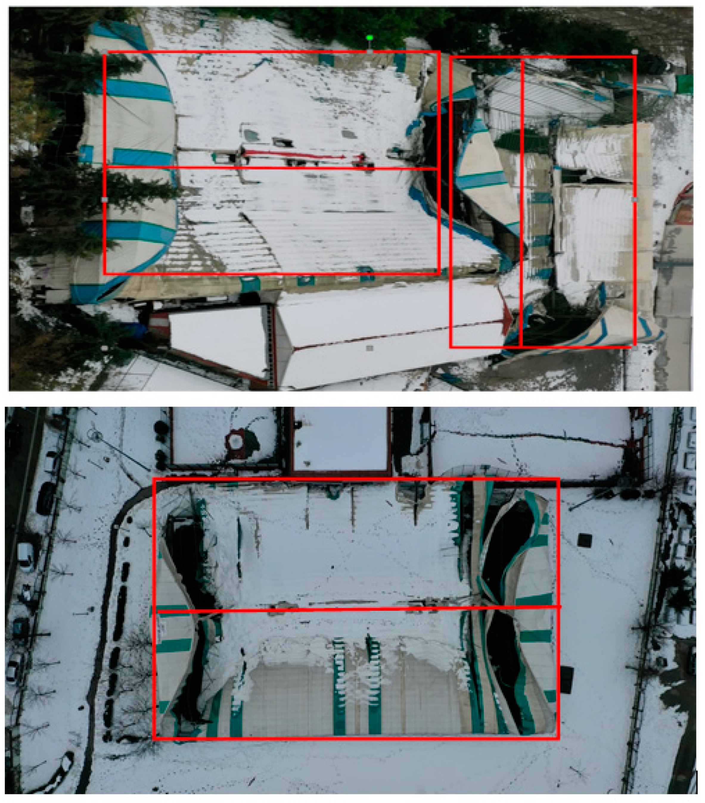
4. Investigations of the Collapse Mechanism of the Structures

Damage to the primary load-bearing components may result in a partial or total collapse of the structure. The top views of the collapsed structures are given in Figure 3 on the day of the collapse. The observed damage modes were identified during visual inspections, and the reasons for the damage are discussed below.
The regions exposed to corrosion are approximately illustrated according to the field observations in the section and plan views of the structures in Figure 4. The welding method and workmanship of the purlin connections were not very good, and some of the profiles were broken from the welds after the collapse, as shown in Figure 5. Moreover, corrosion problems were noticed at the purlin connections to the roof system in Figure 5. These conditions made the roof system more prone to collapse. The connections should be resistant to bending and displacement under service loads because the capacity of the connections should be more than or at least as much as the load-carrying capacity of the purlin profiles, according to the relevant standards.
Roof and façade wind stability braces were examined in situ and are presented in Figure 6. It was observed that the braces failed due to inadequate welding and excessive vertical deflections. This indicates that the capacities of the brace members and their connections to the truss columns and the roof rafters were not enough to carry their service loads.
The deficiencies in the connections of the column support plates to the reinforced concrete foundation were observed and are shown in Figure 7. In the on-site investigations, it was observed that reinforcing steel bars were used instead of anchor rods to connect the support plates to the foundation, and the number of bars was even less than the value required for the design of the connections. The cross-sectional loss occurred on the steel bars as well as on the truss column members due to corrosion (Figure 7). In addition, the excessive upward displacement of the support plates resulted in the failure of the truss columns.
Looking at the photographs in Figure 5 and Figure 7, high levels of corrosion were detected in the member cross-sections and the connections. These corrosion levels led to the loss of almost entire cross-section areas in some regions of the structures, as shown in Figure 8. The truss column members failed due to excessive corrosion in the support connections. The steel structures should have been built according to the NACE International Standards [25] to prevent or control corrosion problems, and holes should have been drilled to drain the water in the sections, thereby reducing the exposure time of these structural elements to water and the corrosion levels of the sections.
The thicknesses of the profiles in the collapsed structures were designed as equal to or thicker than 2.5 mm; thus, it is supposed that the profiles should not have any stability problems. However, the stability of the structural members and their connections were affected by the high levels of corrosion and improper erections.
In light of all of these observations, the excessive deformations of the open-web curved rafter system triggered by welding problems, the section losses due to corrosion in the support regions, the weak purlin connections, and the overturning problems of the truss columns due to the deficiencies in the anchor rods can all be categorized as the basic mechanisms leading to the collapses of these structures with a loss of global stability.

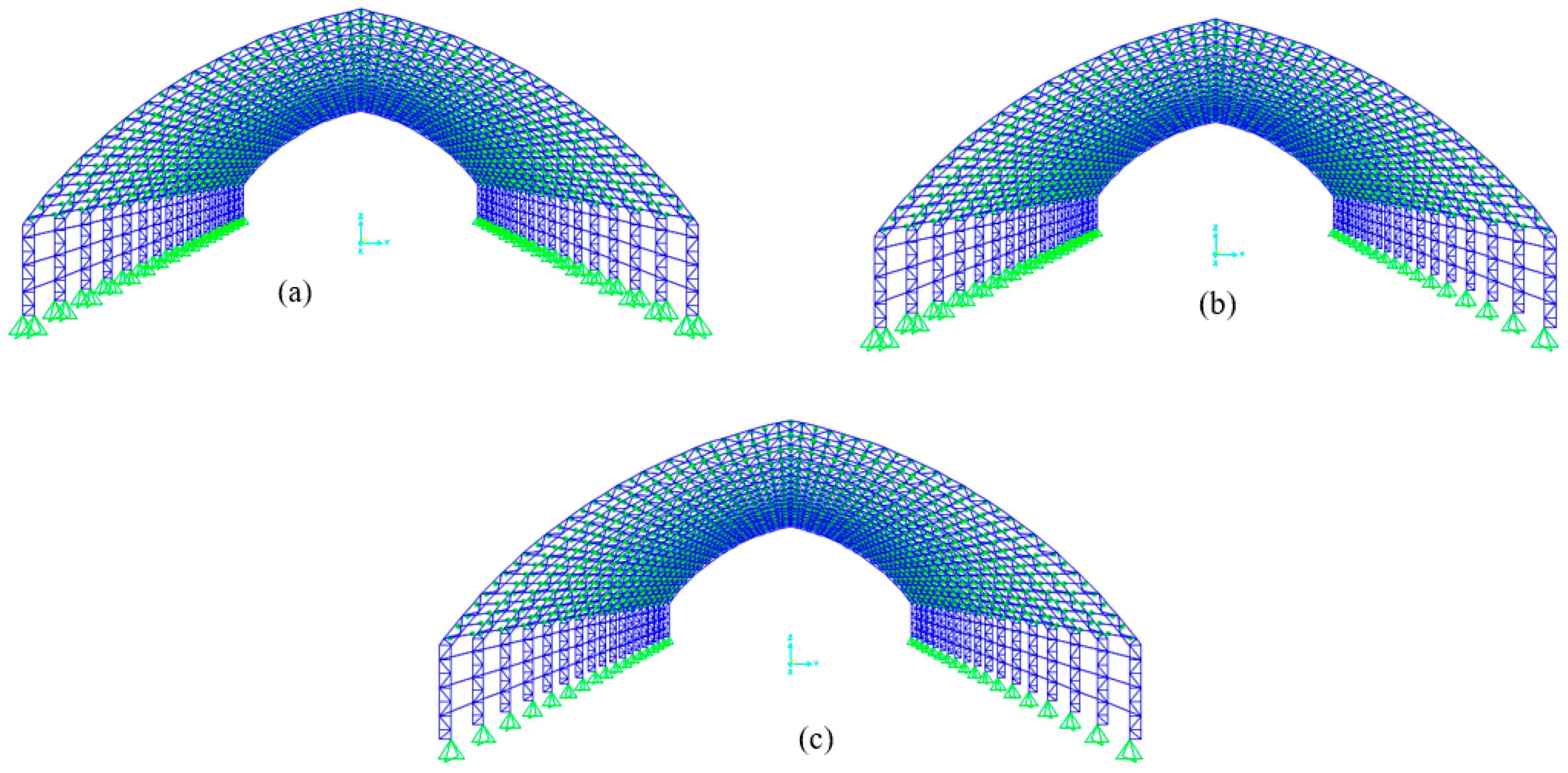
5. Finite Element Analyses of the Structures

5.1. FE Models with Linear Material

The three-dimensional finite element (FE) models of the structures were defined by using SAP2000 v.21.0.0 [26] to verify the collapse mechanisms defined in visual observations and evaluations. The rafter systems of the steel structures were built with different member configurations in some axes of the structures, as shown in Figure 2. Four different rafter systems were considered in four separate models, and the force distribution to each structural element was examined. The finite element models are henceforth referred to as “Model 1”, “Model 2”, “Model 3”, and “Model 4”. The 3-D FE model representation of Model 1 is shown in Figure 9 as an example.
The mechanical properties of the steel material were defined as linear using the measured test results mentioned previously. The cross-sectional dimensions of the profiles were given according to the values specified in the shop drawing and on-site measurements. The snow load on the roof level was considered to be the snow load calculated based on the meteorological data, and it was applied to the purlins as a uniformly distributed load in accordance with TS EN 1991-1-3. In the FE models, wind load effects were not taken into account because no information was obtained in the meteorological report. Along the transverse and longitudinal directions of the structures, simply supported boundary conditions were considered at the bottom of the truss column members where the two vertical, steel, and hollow circular sections connected to the support plates, as shown in Figure 9.
First of all, a total of four simple supports were defined for each plane frame system in each of the FE models (Figure 9a). The number of supports was reduced to three and two for each model because the partial or full contact loss between the column members and the support plates occurred due to the corrosion and upward displacements observed during site investigations (Figure 7 and Figure 8). Each FE model was subjected to a full snow load as computed based on the meteorological data, and they were analyzed under three different boundary conditions. The most critical results of the load-carrying capacity ratios were obtained for different support conditions in each model, as given in Table 1. Model 2 had the rafter system configuration in the shop drawing; thus, the maximum capacity ratios on the structural members for Model 2 with different support conditions are shown in Figure 10 as an example. In all FE models, it was determined that the truss column members close to the support regions yielded the maximum capacity ratios for the models with four supports, whereas the rafter system members close to the truss columns got the maximum values for the models with three and two supports, which was similar to the results given in Figure 10. The capacity ratios increased to 1.500 and 1.325 for the models with three and two support conditions, respectively, as it was anticipated. The results were similar between Model 1 and Model 2, as given in Table 1. However, the capacity ratios increased for Model 3 and Model 4 with four simple supports because the moment effect occurred due to the purlins not coinciding with the nodal points of the rafters, as shown in Figure 11. Moreover, the capacity ratios of each model with three supports were higher than those of the models with two supports, as presented in Table 1. This shows that the structural system as well as the load distribution became asymmetric when three supports were defined. In addition, the damage observed in the field on the left and right sides of the rafter system’s connections with truss columns in Model 4 are given in Figure 12. The damage modes show consistency with the maximum capacity ratios for Model 4 with three and two supports, as shown in Table 1, exceeding the capacity of the rafter members more than 11 and 9 times, respectively.

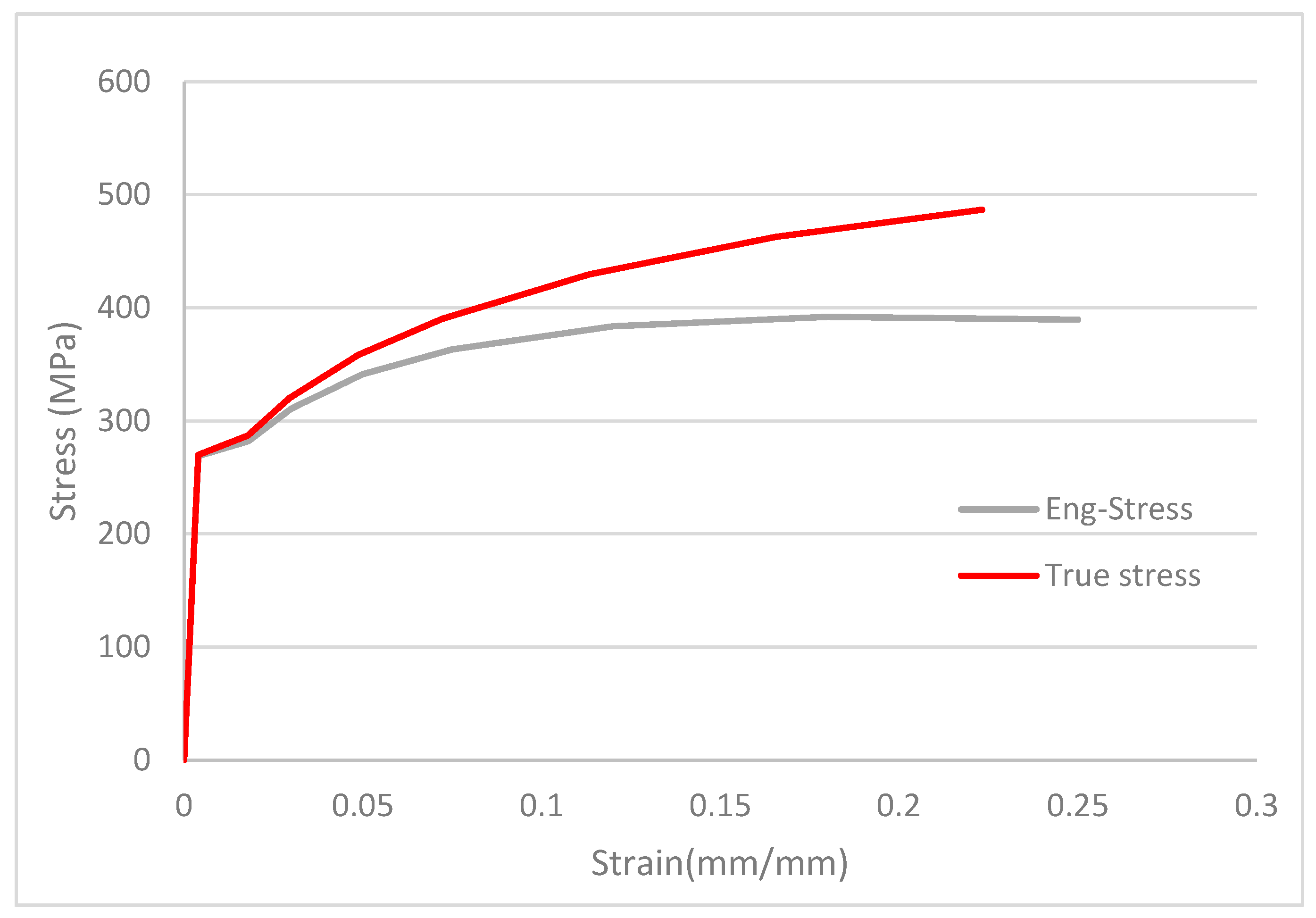
5.2. FE Models with Nonlinear Material

Detailed models of the four different rafter systems were created with ABAQUS FEA v. 6.14 [27] because the models defined with linear material properties in SAP2000 yielded high stresses, and the capacities of the members exceeded the strength limits. In the ABAQUS FEA model, the structural elements were defined using two-node linear (straight) beam elements. In order to decrease solution time, only the first five axes of the structures were modeled due to the symmetry of the structures. The material characteristics of the structural steel were taken into account based on the test results shown in Figure 13. Nonlinear material behavior was defined in ABAQUS FEA. The snow load on the roof was considered to be the same as in the SAP2000 models. The mesh size of the elements was chosen as 40 mm after the mesh optimization of finite element analysis. Boundary conditions were defined the same way as in the previous models. Three different support cases were examined due to the corrosion that occurred at the support plates, as mentioned previously.
Von–Mises stress distributions were obtained for the different rafter models. The comparisons of the analysis results were made for the rafter system on the second axis because it was subjected to full snow loading. Although the Von–Mises stress values formed in different rafter systems with four simple supports did not reach the yield strength of the steel material, the stresses exceeded the yield capacity in some members of the rafter system in all FE models with three and two supports, as shown in Figure 14. It was observed that the stress values were similar for different rafter systems with the same number of supports (Table 2). High stress concentrations were found along the bottom chord members of the rafter at the connection region to the column profiles (Figure 14). This situation was also observed in the collapsed structures, as shown in Figure 12.
The vertical displacement values were determined at the center of the middle rafter for each FE model and compared with the allowable displacement limit of L/300 prescribed by TS 648 under the self-weights of the members and the snow loads. The vertical ridge displacements gave similar results for the rafter models having the same number of supports, as given in Table 3. It was observed that the vertical displacements in the models with three and two simple supports reached almost four times the values obtained in the models with four supports and exceeded the allowable limit specified in the code (L/300 = 30 m/300 = 0.1 m = 100 mm). This shows that the structures did not meet the allowable limit of vertical displacement due to corrosion damage in the support regions and to deficiencies in the anchor rods.

6. Discussion

Detailed measurements of the structural elements could not be taken for safety reasons while the on-site investigations of the collapsed structures were carried out. However, some structural system differences were observed based on these site investigations. Different FE models were created with field observations and measurements because the complete static project and detailed drawings of the structures did not exist. The main reasons for the collapses of the structures were investigated by comparing the FE models.
The Von–Mises stress distributions were evaluated in each model in ABAQUS. The stress results were not very high in the models, though the structures collapsed under these loads. In spite of the steel material properties being defined as nonlinear, the stress values obtained in the structural elements were slightly above the yield strength of the steel material. It is thought that the main reason for each collapse was the excessive amount of corrosion in each system. During the in situ examinations of the structures, local corrosion in many structural members and connection regions as well as section and joint losses due to this corrosion were observed (Figure 5, Figure 7, and Figure 8). Although the section losses in the purlin profiles and their connections only affected local load distribution, the section losses that occurred in the support connections affected the load distribution of the entire frame system. Therefore, the section loss in the supports is estimated to be the main reason for the collapses.
The most critical results of the load-carrying capacity ratios were obtained for each model in SAP2000. The capacity ratios yielded very high values in models with three and two simple supports, although the stresses in the structural members were close to the yield strength of the steel in the ABAQUS FE models. However, the highest results of the structural members in the models created in both FE programs were in the vicinity of the connections of the rafter system with truss columns, as shown in Figure 10c and Figure 14. In addition, it was observed that there was a similar relationship between the members with high stress and the buckled members in the collapsed structures, as given in Table 2.
In light of these investigations, damage to the supports of these structures are thought to be the main factor that increased the stress states of these systems. In the first models with four simple supports, the stress values did not reach the yield strength of the material in any of the members in the system. Specifically, the stress values at the bottom chord profiles of the open-web curved rafter system connected to the truss columns increased approximately four times and exceeded the material yield strength in the models with three and two supports. This represents that one of the major factors causing the collapse of these systems was the damage to the support regions.
Looking at the photographs of the systems after collapse in Figure 3, it is seen that the roof ridge lines were approximately in the middle of the system. Thus, it is thought that was no disruption to the symmetry in the system at the time of collapse.

7. Conclusions

In this study, the collapse mechanism of the studied steel structures was defined according to on-site examinations and observations. The capacities of the structural members in these systems were obtained based on the results of finite element analyses to show elements’ contributions to the mechanisms of collapse. The following conclusions can be drawn:
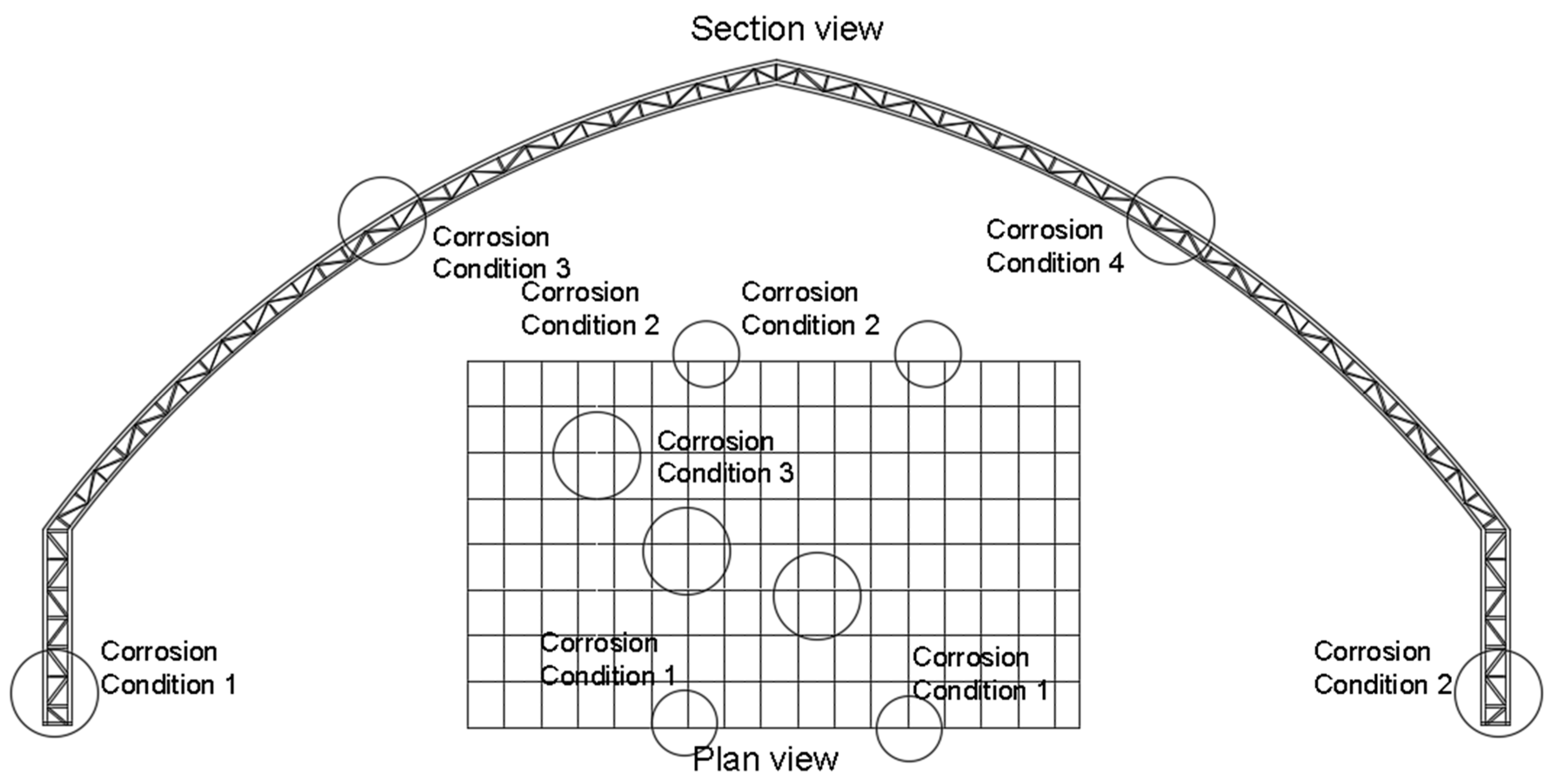
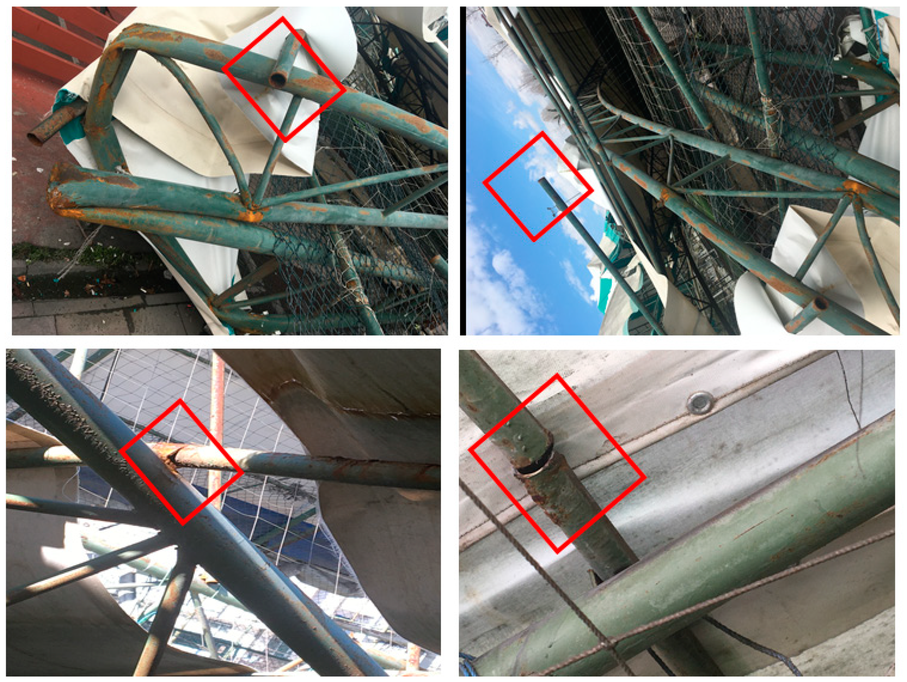
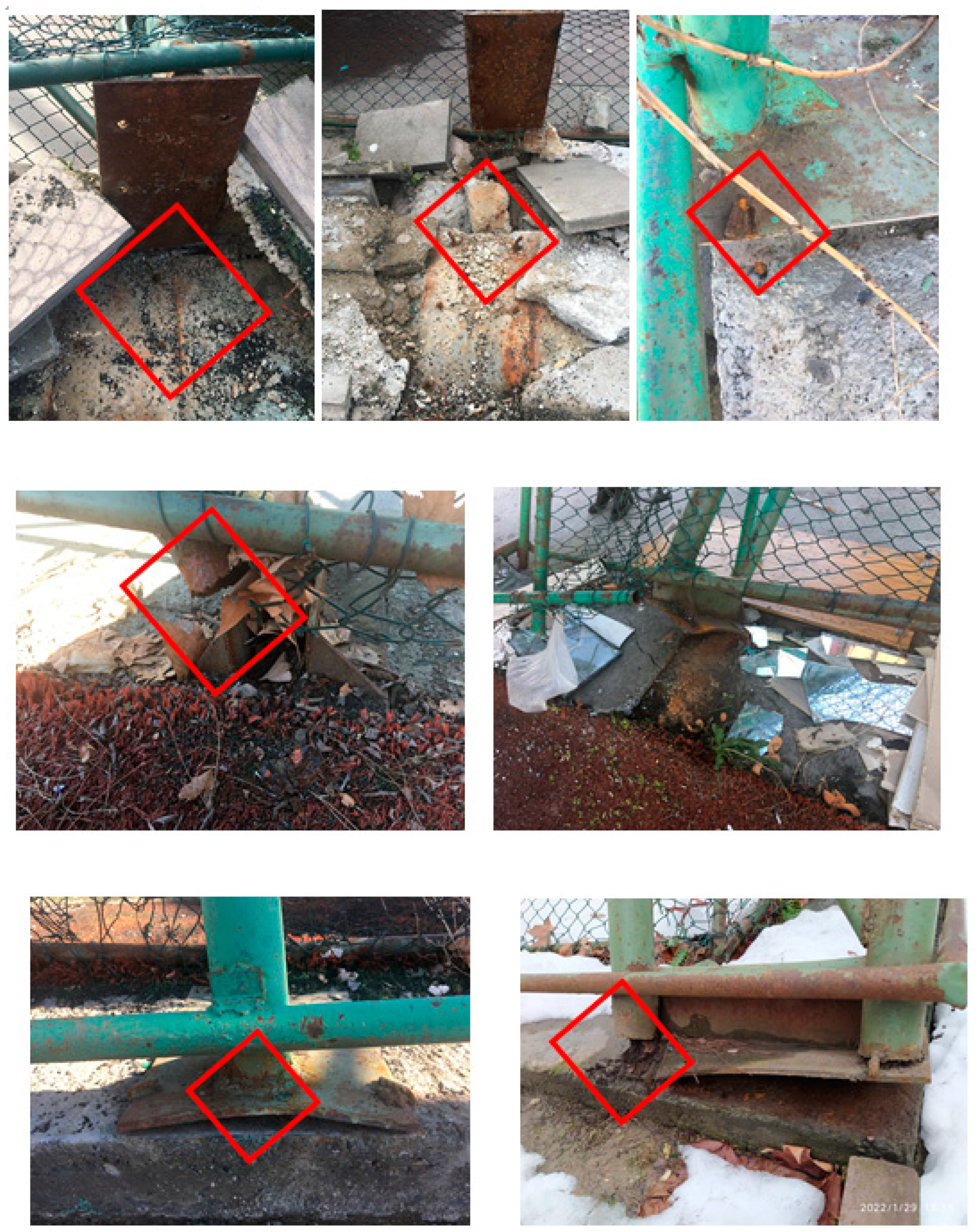
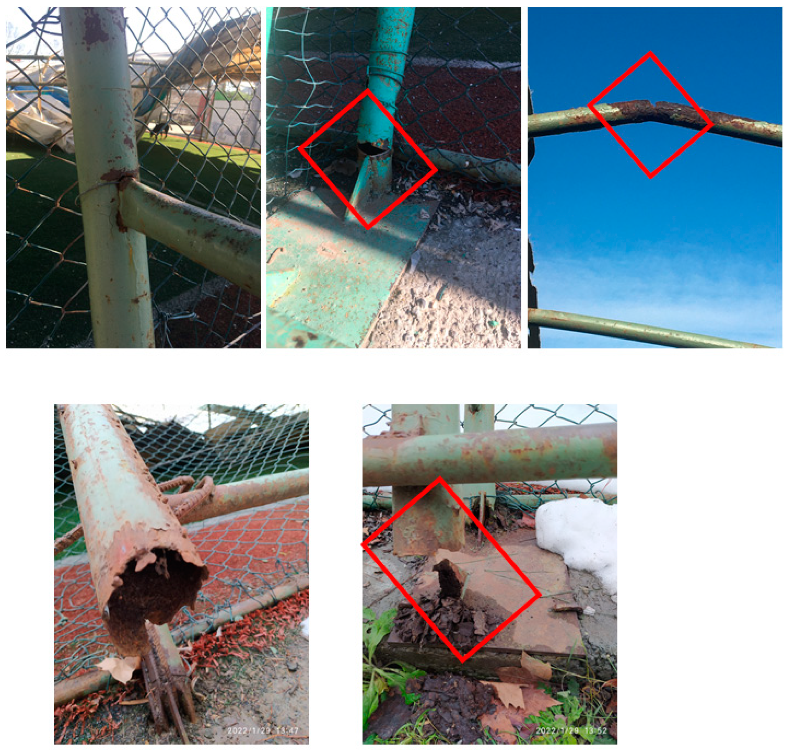
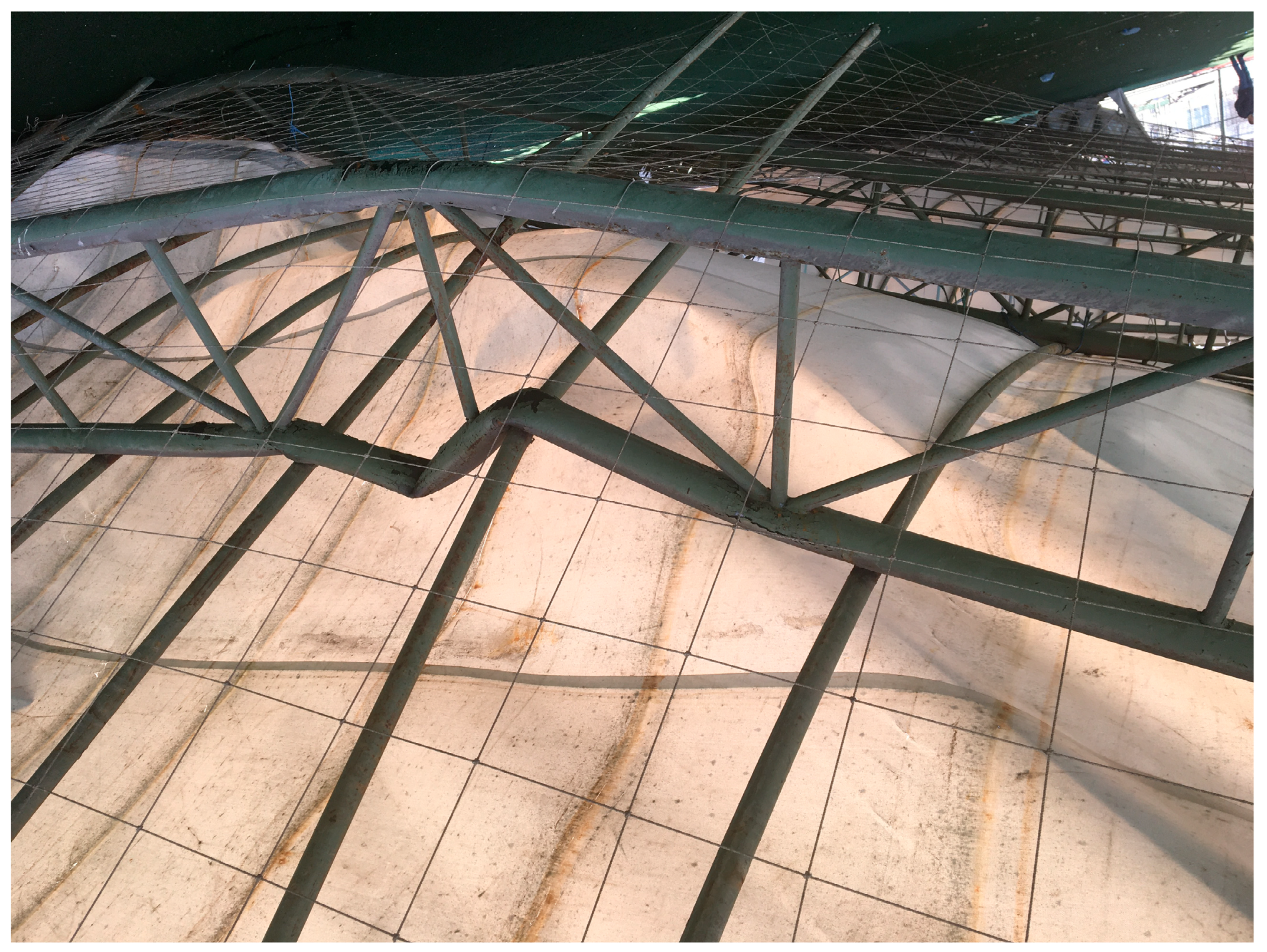
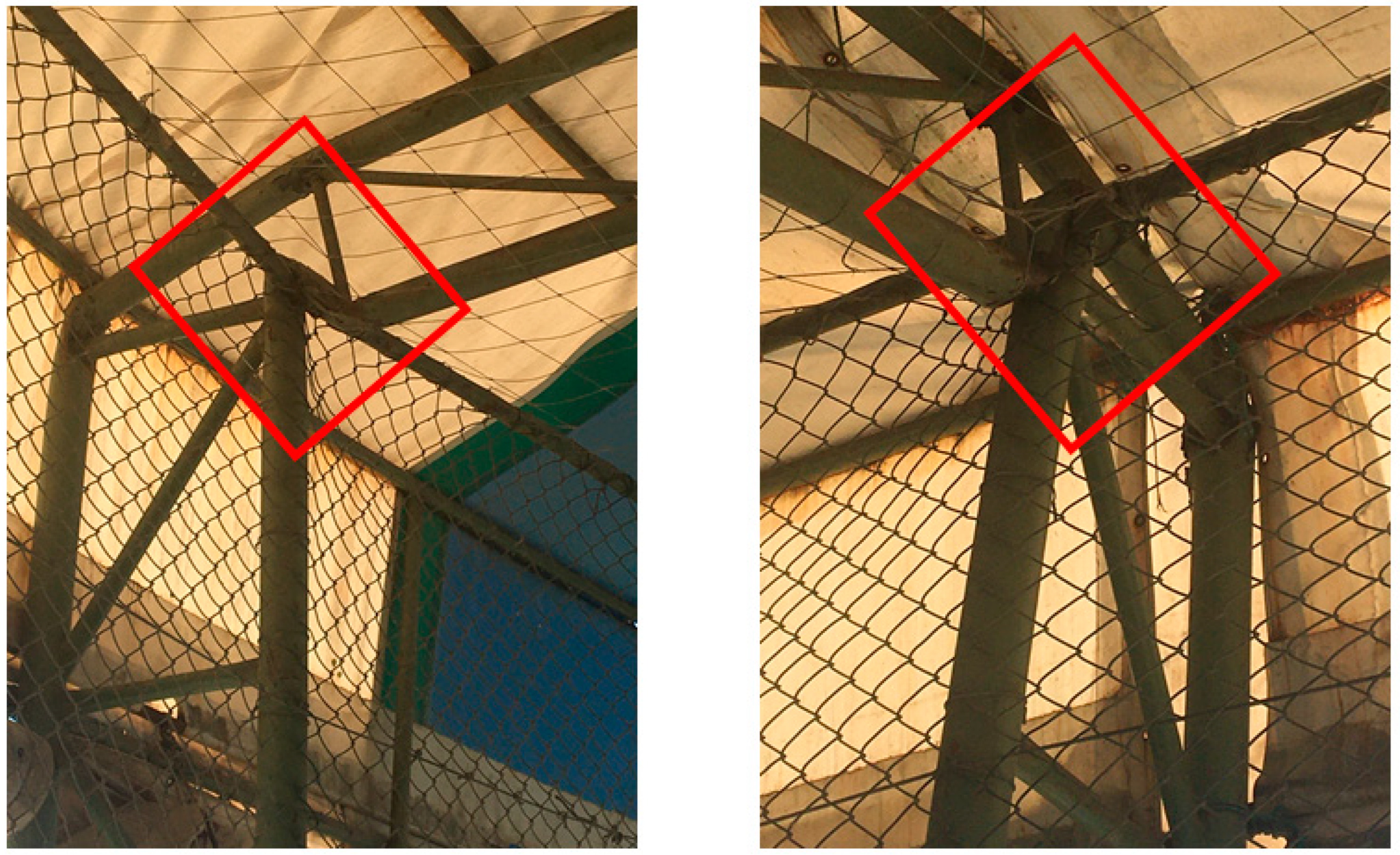
  • The structures were exposed to excessive corrosion in general, especially in the support connections of structural members. Thus, the connections failed to provide load transfer and contributed significantly to the collapses.
  • Improper erections and deficiencies in the structural systems built on-site because of inadequate building inspection control during the construction of the buildings could be the primary reasons behind the failure. Specifically, the welding in the connections of the structural members were not adequate to carry their loads, and the anchor rods in the support regions of the columns were not in accordance with the project drawing.
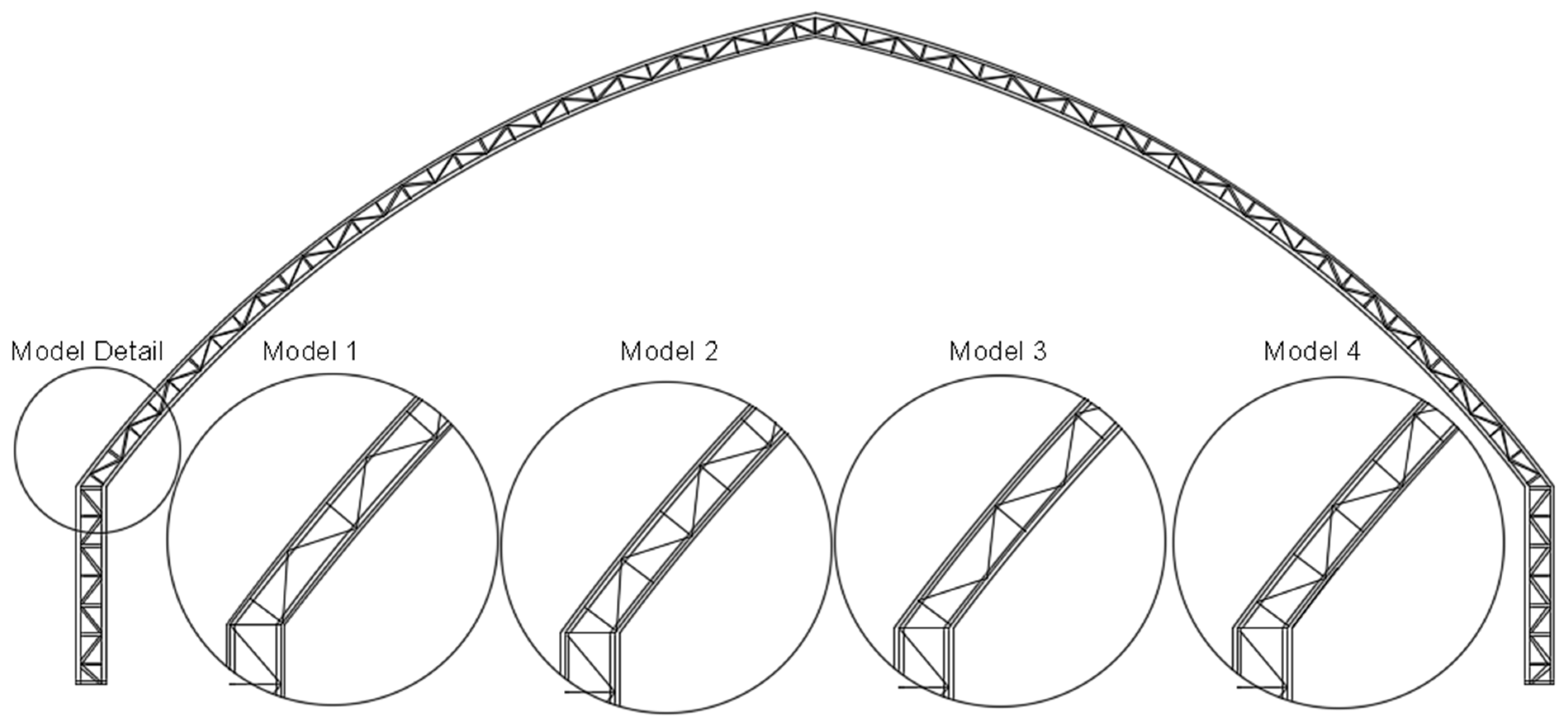
  • The differences in the open-web curved rafter systems affected the load distributions in the structures, as determined in the simulations.
  • Corrosion problems in the support regions led to section and joint losses, as observed. According to the numerical simulations, the load-carrying capacity ratios and the stress states of the structural members increased, and the structures became unable to withstand loads. It is thought that the joint losses in the support regions contributed highly to the collapse of the structures.
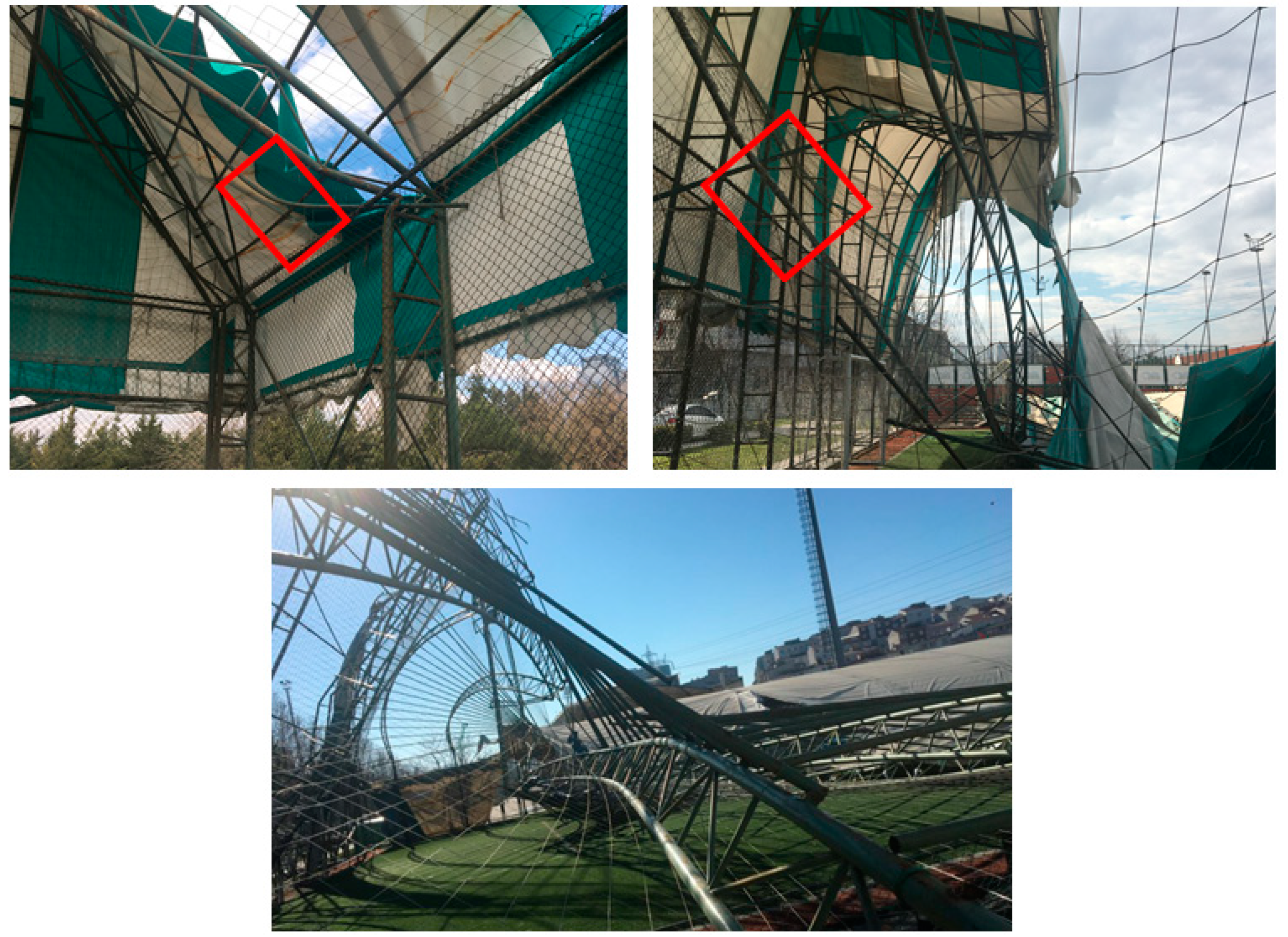
  • The structures remained stable under their existing corrosion effects before the snowfall; however, they collapsed suddenly under a snow load less than their design value. This situation revealed the necessity to detect corrosion within steel hollow circular sections exposed to atmospheric conditions.
  • The design snow load value, calculated according to the standard, was greater than the snow load at the time of collapse, although the static projects of the structures were missing and the exact design load values were impossible to find. It can be deduced that if there was no excessive corrosion and no improper erections, then the snow load would not have caused the collapses.

Author Contributions

Conceptualization, Z.F.A. and F.A.; Methodology, Z.F.A. and F.A.; software, F.A.; investigation, Z.F.A. and F.A.; writing—original draft preparation, F.A.; writing—review and editing, Z.F.A.; visualization, Z.F.A. and F.A. All authors have read and agreed to the published version of the manuscript.

Funding

This research did not receive any specific grant from funding agencies in the public, commercial, or not-for-profit sectors.

Institutional Review Board Statement

Not applicable.

Data Availability Statement

Data sharing not applicable. No new data were created.

Conflicts of Interest

The authors declare no conflict of interest.

References

  1. Biegus, A.; Rykaluk, K. Collapse of katowice fair building. Eng. Fail. Anal. 2009, 16, 1643–1654. [Google Scholar] [CrossRef]
  2. Brencich, A. Collapse of an industrial steel shed: A case study for basic errors in computational structural engineering and control procedures. Eng. Fail. Anal. 2010, 17, 213–225. [Google Scholar] [CrossRef]
  3. Caglayan, O.; Yuksel, E. Experimental and finite element investigations on the collapse of a mero space truss roof structure—A case study. Eng. Fail. Anal. 2008, 15, 458–470. [Google Scholar] [CrossRef]
  4. del Coz Díaz, J.; Nieto, P.G.; Vilán, J.V.; Sierra, J.S. Non-linear buckling analysis of a self-weighted metallic roof by fem. Math. Comput. Model. 2010, 51, 216–228. [Google Scholar] [CrossRef]
  5. Korkmaz, H.H.; Dere, Y.; Özkılıç, Y.O.; Bozkurt, M.B.; Ecemiş, A.S.; Özdoner, N. Excessive snow induced steel roof failures in Turkey. Eng. Fail. Anal. 2022, 141, 106661. [Google Scholar] [CrossRef]
  6. Piskoty, G.; Wullschleger, L.; Loser, R.; Herwig, A.; Tuchschmid, M.; Terrasi, G. Failure analysis of a collapsed flat gymnasium roof. Eng. Fail. Anal. 2013, 35, 104–113. [Google Scholar] [CrossRef]
  7. Zhao, Z.; Zhang, H.; Xian, L.; Liu, H. Tensile strength of Q345 steel with random pitting corrosion based on numerical analysis. Thin-Walled Struct. 2019, 148, 106579. [Google Scholar] [CrossRef]
  8. Sheng, J.; Xia, J. Effect of simulated pitting corrosion on the tensile properties of steel. Constr. Build. Mater. 2017, 131, 90–100. [Google Scholar] [CrossRef]
  9. Zhang, Z.; Xu, S.; Li, R. Comparative investigation of the effect of corrosion on the mechanical properties of different parts of thin-walled steel. Thin-Walled Struct. 2020, 146, 106450. [Google Scholar] [CrossRef]
  10. Garbatov, Y.; Parunov, J.; Kodvanj, J.; Saad-Eldeen, S.; Soares, C.G. Experimental assessment of tensile strength of corroded steel specimens subjected to sandblast and sandpaper cleaning. Mar. Struct. 2016, 49, 18–30. [Google Scholar] [CrossRef]
  11. Zhao, N.; Zhang, C. Experimental Investigation of the Mechanical Behavior of Corroded Q345 and Q420 Structural Steels. Buildings 2023, 13, 475. [Google Scholar] [CrossRef]
  12. Czarnecki, A.A.; Nowak, A.S. Time-variant reliability profiles for steel girder bridges. Struct. Saf. 2008, 30, 49–64. [Google Scholar] [CrossRef]
  13. Gholizad, A.; Golafshani, A.; Akrami, V. Structural reliability of offshore platforms considering fatigue damage and different failure scenarios. Ocean Eng. 2012, 46, 1–8. [Google Scholar] [CrossRef]
  14. Ni, Y.; Ye, X.; Ko, J. Monitoring-based fatigue reliability assessment of steel bridges: Analytical model and application. J. Struct. Eng. 2010, 136, 1563–1573. [Google Scholar] [CrossRef]
  15. Li, L.; Mahmoodian, M.; Li, C.-Q. Prediction of fatigue failure of corrosion affected riveted connections in steel structures. Struct. Infrastruct. Eng. 2020, 16, 1524–1538. [Google Scholar] [CrossRef]
  16. Revie, R.W. Corrosion and Corrosion Control: An İntroduction to Corrosion Science and Engineering; John Wiley & Sons: Hoboken, NJ, USA, 2008. [Google Scholar]
  17. Adasooriya, N.; Siriwardane, S. Remaining fatigue life estimation of corroded bridge members. Fatigue Fract. Eng. Mater. Struct. 2014, 37, 603–622. [Google Scholar] [CrossRef]
  18. Zampieri, P.; Curtarello, A.; Pellegrino, C.; Maiorana, E. Fatigue strength of corroded bolted connection. Frattura ed Integrità Strutturale 2018, 12, 90. [Google Scholar] [CrossRef] [Green Version]
  19. Rodriguez, R.; Jordon, J.; Allison, P.; Rushing, T.; Garcia, L. Corrosion effects on fatigue behavior of dissimilar friction stir welding of high-strength aluminum alloys. Mater. Sci. Eng. A 2019, 742, 255–268. [Google Scholar] [CrossRef]
  20. Zampieri, P.; Curtarello, A.; Maiorana, E.; Pellegrino, C. A review of the fatigue strength of shear bolted connections. Int. J. Steel Struct. 2019, 19, 1084–1098. [Google Scholar] [CrossRef]
  21. Giorgetti, V.; Santos, E.A.; Marcomini, J.B.; Sordi, V.L. Stress corrosion cracking and fatigue crack growth of an api 5l x70 welded joint in an ethanol environment. International J. Press. Vessel. Pip. 2019, 169, 223–229. [Google Scholar] [CrossRef]
  22. ASTM. Standard test methods for tension testing of metallic materials. In Annual Book of ASTM Standards; ASTM: West Conshohocken, PA, USA, 2001. [Google Scholar]
  23. TS EN 1991-1-3; Eurocode 1-Actions on Structures-Part 1–3: General Actions-Snow Loads. Institute of Turkish Standard (TSE): Ankara, Turkey, 2007.
  24. TS 498; Design loads for buildings. Institute of Turkish Standard (TSE): Ankara, Turkey, 1997.
  25. Roberge, P.R. Handbook of Corrosion Engineering; McGraw-Hill Education: New York, NY, USA, 2019. [Google Scholar]
  26. SAP2000; Advanced 21.0.0. Sap2000 Computers and Structures Inc.: Berkeley, CA, USA, 2019.
  27. Dassault Systemes Simulia Corporation. Abaqus V; 6.14 Documentation; Dassault Systemes Simulia Corporation: Johnston, RI, USA, 2014. [Google Scholar]
Figure 1. The sectional view of the structures.
Buildings 13 00826 g001
Figure 2. Different configurations of the rafter systems.
Buildings 13 00826 g002
Figure 3. Top views of the collapsed structures.
Buildings 13 00826 g003
Figure 4. Corrosion conditions of the structures.
Buildings 13 00826 g004
Figure 5. Observed damage on purlin connections.
Buildings 13 00826 g005
Figure 6. Roof and façade wind stability braces.
Buildings 13 00826 g006
Figure 7. Failure of the column support plates.
Buildings 13 00826 g007
Figure 8. Corrosion damage to structural members.
Buildings 13 00826 g008
Figure 9. Boundary conditions of Model 1: (a) four supports; (b) three supports; (c) two supports.
Buildings 13 00826 g009
Figure 10. The maximum capacity ratios for Model 2 with (a) four supports; (b) three supports; (c) two supports.
Buildings 13 00826 g010
Figure 11. Bending moment effect observed in purlin connections to the rafters.
Buildings 13 00826 g011
Figure 12. Observed damage at the end of rafter system in Model 4.
Buildings 13 00826 g012
Figure 13. Stress–strain curves.
Buildings 13 00826 g013
Figure 14. The Von–Mises stress distributions in Model 2 with two supports.
Buildings 13 00826 g014
Table 1. The maximum capacity ratios for different FE models.
Four SupportsThree SupportsTwo Supports
Model 10.6081.3451.221
Model 20.6171.5001.325
Model 30.9976.7865.410
Model 40.95311.7559.049
Table 2. The maximum Von–Mises stresses for different FE models (units in MPa).
Four SupportsThree SupportsTwo Supports
Model 1165.70275.70271.20
Model 2166.30274.70273.70
Model 3165.70269.50273.10
Model 4166.40269.60273.50
Table 3. The maximum vertical displacements for different FE models (units in mm).
Four SupportsThree SupportsTwo Supports
Model 131.72117.80116.90
Model 231.83116.40116.70
Model 331.71116.10116.50
Model 431.83116.50116.80
Disclaimer/Publisher’s Note: The statements, opinions and data contained in all publications are solely those of the individual author(s) and contributor(s) and not of MDPI and/or the editor(s). MDPI and/or the editor(s) disclaim responsibility for any injury to people or property resulting from any ideas, methods, instructions or products referred to in the content.

