Article

Mechanism and Design Method of Load Transfer into Concrete-Filled Steel Tubular Arch Ribs through Perfobond-Rib-Shear Connectors

1
School of Highway, Chang’an University, Xi’an 710064, China
2
School of Civil Engineering, Chongqing University, Chongqing 400044, China
3
Engineering Design and Research Institute of CCCG Second Highway Engineering, Xi’an 710199, China
*
Author to whom correspondence should be addressed.
Buildings 2023, 13(3), 807; https://doi.org/10.3390/buildings13030807
Submission received: 31 December 2022 / Revised: 22 February 2023 / Accepted: 24 February 2023 / Published: 18 March 2023
(This article belongs to the Section Building Structures)

Abstract

:
In terms of load transfer, the design of the joints in concrete-filled steel tubular (CFST) arch bridges is more critical than that in buildings due to the higher likelihood of steel–concrete-interface debonding. To improve the contact at the steel–concrete interface, a novel arch rib was manufactured by longitudinally welding perfobond-rib-shear connectors to the inner surface of a steel tube and then filling the tube with concrete. In this study, extensive numerical and analytical investigations on the mechanism of introducing loads into CFST arch ribs through perfobond-rib-shear connectors were carried out. A deck CFST arch bridge, namely, the Shuangbao Bridge in China, was selected as a typical application location. The design parameters, including the geometric dimensions of the perfobond-rib-shear connector and the arrangement of the perfobond rib along the cross-section and longitudinal section of the arch rib, were evaluated. The design flow for the joint with perfobond-rib-shear connectors between the vertical columns and the CFST arch ribs was proposed. To improve the load-transfer efficiency, the design scheme of the joint in the Shuangbao Bridge was optimized by replacing the weld studs with perfobond ribs. Significant increases of 1.84–4.02 in the shear resistance were found for the perfobond ribs compared to the welded studs. Additionally, the fabrication of the perfobond ribs was more convenient compared to that of the welded studs.

1. Introduction

In the past 20 years, due to their excellent structural performance and attractive appearance, more than 400 concrete-filled steel tubular (CFST) arch bridges have been constructed in China [1,2], and specific design guidelines for CFST arch bridges have been issued. However, there are still some difficulties in the design of CFST arch bridges. In the practical engineering process, the vertical column and hanger anchor system are directly connected to the outer surface of the CFST arch rib. In this case, the load is applied to the steel tube first and then transferred to the concrete core by a steel–concrete bond through an “introduction length” to fulfill the composite action. Additionally, in consideration of the confinement effect, the hoop stress of the steel tube increases while the allowable longitudinal stress decreases, in compliance with the von Mises yield criterion, leading to the premature failure of the steel tube [3,4,5,6]. Therefore, it is critical to create a reasonable design of the joint between the vertical column (or hanger anchor system) and CFST arch rib to guarantee the load transfer.
Wang et al. [7], Dong et al. [8], and Naghipour et al. [9] investigated the bond strengths of CFST columns using push-out tests. It was demonstrated that the bond strength between the steel tube and the concrete core must be very small to result in a longer load-transfer time. Furthermore, for interface debonding, the load cannot be effectively introduced into the concrete core. For the design of beam–column joints in buildings, it is much easier to guarantee the load transfer. Shear connectors, such as gusset plates, bearing rings, and stiffeners, are normally placed within the inner surface to transfer the beam reaction, while the quality of the concrete in CFST structures in buildings is less affected by the ambient temperature, meaning a reliable steel–concrete bond can be easily obtained [10,11,12,13,14,15,16,17,18]. However, for the design of joints between vertical columns and CFST arch ribs, it is difficult to guarantee the load transfer. On one hand, the shear force applied to the arch rib is larger than that in the building. On the other hand, it was proven that steel–concrete-interface debonding is more likely in CFST arch bridges than in CFST buildings because of the concrete shrinkage and creep that occur due to the complications of ambient temperatures [19,20].
To address this problem, a novel arch rib was manufactured by Liu et al. by longitudinally welding perfobond ribs to the inner surface of a steel tube and then filling the tube with concrete, namely a CFST arch rib stiffened with perfobond ribs [21,22]. Additionally, Jiang et al. [23,24,25,26,27] and Cheng et al. [28] conducted extensive studies on these novel structures in terms of the steel–concrete-interface behavior, the buckling behavior of the steel tube, the confinement effect of the member, and the static and fatigue behavior of the joint. It was found that the perfobond ribs worked as both stiffeners and shear connectors, as follows: (1) as the stiffener, the perfobond rib improved the buckling resistance of the steel tube, reduced the stress concentration of the joint, and enhanced the confinement effect of the arch rib; (2) as the shear connector, the perfobond rib significantly enhanced the steel–concrete bond and prevented the steel–concrete interface from debonding under temperature changes.
Based on the studies mentioned above, in this paper, we further study the mechanism for introducing loads into CFST arch ribs through perfobond-rib-shear connectors. A typical application scenario of Shuangbao Bridge in China was selected as the research object and the design parameters are evaluated, namely the geometric dimensions of the perfobond rib and the arrangement of the perfobond rib along the cross-section and longitudinal section of the arch rib. The design flow for the novel joint with perfobond rib-shear-connectors is provided.

2. Literature Review on the Bond Behaviors of CFST Columns

To date, scholars have conducted numerous studies on the steel–concrete bonding of CFST columns. Meanwhile, some design guidelines have provided bond-behavior models for the beam–column joints in buildings. A thorough understanding of the bond behaviors of CFST columns is helpful to reveal the load-transfer mechanism of CFST arch ribs. Therefore, in the following sections, we will review the experimental research on steel–concrete bonds and the bond-behavior models recommended by the design guidelines.

2.1. Experimental Study on Steel–Concrete Bonds

Figure 1 illustrates the typical bond stress–slip curves at the steel–concrete interface. It has been demonstrated that the bond strength is composed of three parts: chemical adhesion, physical interlocking (also called micro-interlocking), and frictional resistance (also called macro-interlocking) [29]. As shown in Figure 1a, the typical bond stress–slip curve has a significant peak point at the end of stage I. This is because the initial frictional resistance is lower than the sum of the chemical adhesion and physical interlocking, meaning a drop in the bond stress can be observed after the chemical bond is broken. Additionally, three kinds of curve, such as a, b, and c, are present, depending on the magnitude of the frictional resistance. Conversely, Figure 1b illustrates the typical bond stress–slip curve without a peak point at the end of stage I. This indicates that the initial frictional resistance is larger than the sum of the chemical adhesion and physical interlocking, which can normally be found in the push-out test with a smooth steel–concrete interface.
In general, the maximum bond stress at the end of stage I (the point of bond loss) is defined as the bond strength τu. At stage I, an approximately linear relationship between bond stress and relative slip can be found; therefore, the tangent slope in this stage can be defined as the shear modulus. Table 1 [30,31,32,33,34,35,36,37,38] lists a summary of the push-out test results of CFST columns. High scatter values were found for the measured bond strength in the range of 0.01–3.65 MPa due to the influence of factors such as the specimen dimensions, smoothness of the steel–concrete interface, concrete strength, concrete age, etc. For the shear modulus, only Liu et al. [37,38] provided the value of 0.165 MPa.

2.2. Bond-Behavior Model in Design Guidelines

Table 2 summarizes the bond-behavior models for beam–column joints in buildings recommended by the design guidelines, where L is the length of the CFST column, and D is the diameter of the steel tube. In consideration of the effect of the high scatter on the measured bond strength, lower values are usually taken as the design value of the bond strength τd in current design guidelines. Among those, the most conservative value of τd is 0.23 MPa, as specified in DBJ/T13-51-2010. Furthermore, the steel–concrete contact area for load transfer should be known; it is determined by the bond-transfer length lx, the bond-transfer circumference, luz, and the region of the introduction, for which only Eurocode 4 and ANSI-AISC 360-05 provide the relevant provisions.

3. Mechanism of Load Introduction into CFST Arch Ribs through Steel–Concrete Bond

3.1. Force–Equilibrium Relationship in the Load Transfer

The connection between the vertical column and the CFST arch rib in the deck arch bridge is taken as a typical joint. 
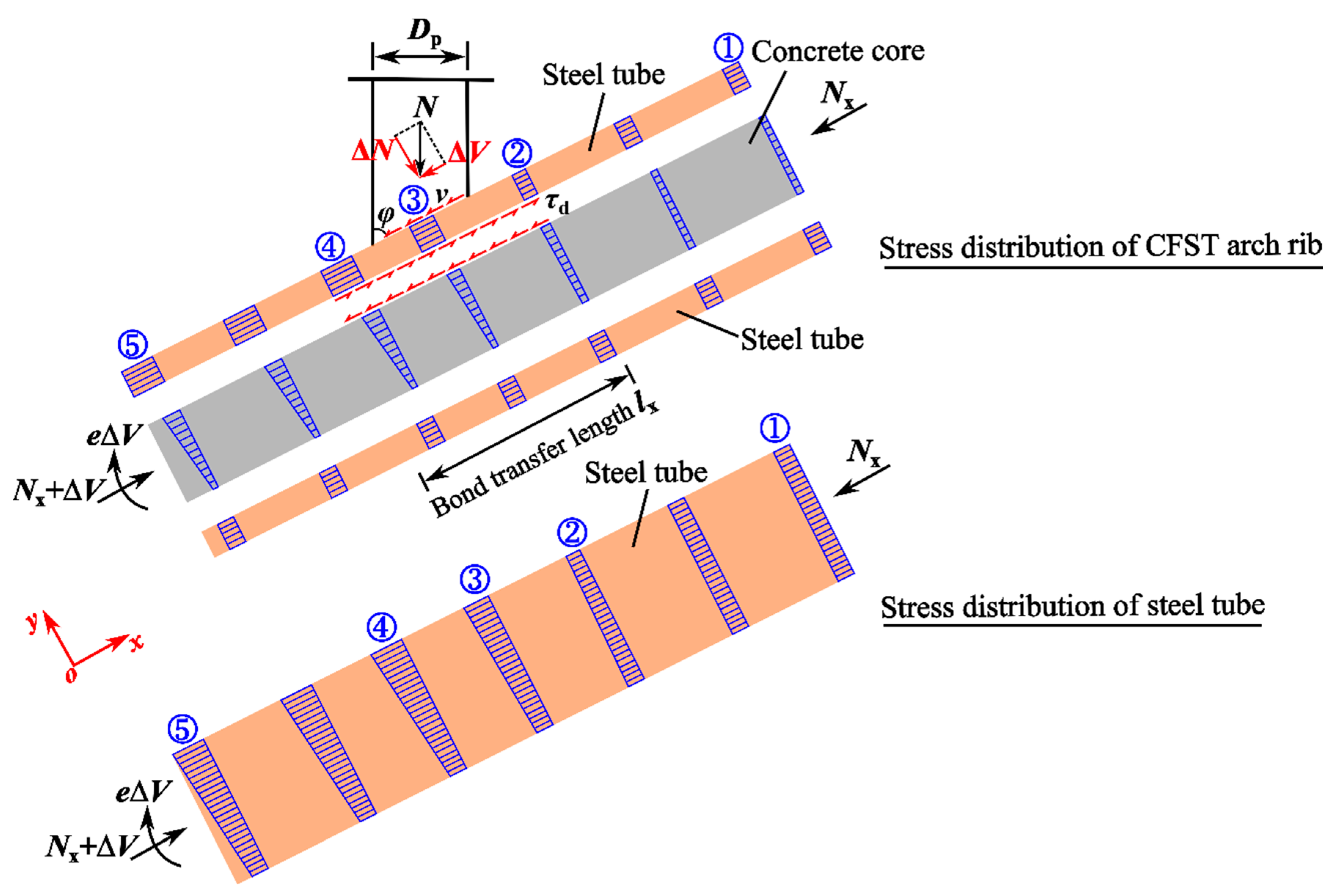
Figure 2 illustrates the force–equilibrium relationship for the load transfer in this typical joint. The curved-arch axis in the region of the introduction length can be assumed as a straight line. Furthermore, the x, y, and z directions are assumed to run along the arch axis, perpendicular to the arch axis, and perpendicular to the plane, respectively.
As shown in Figure 2, the CFST arch rib in the cross-section ① bears the axial force, Nx, which is transferred from the vertical column above this cross-section. Meanwhile, the steel tube and concrete core work together to resist the axial force based on the deformation-compatibility principle. Uniformly distributed compressive stresses can be found on the steel tube (σs1) and concrete core (σc1), respectively, in compliance with the axial-stiffness ratio, as follows:
σ s 1 = E s N x E s A s + E c A c
σ c 1 = E c N x E s A s + E c A c
where Es and Ec are the elastic moduli of the steel and concrete, respectively, and As and Ac are the cross-sectional areas of the steel tube and concrete core, respectively.
The vertical load N transferred from the deck system is directly applied to the outer surface of the steel tube, which can be divided into vertical and horizontal force components (ΔN and ΔV), as presented in Figure 2. It is assumed that the horizontal force component ΔV is uniformly distributed on the top face of the steel tube within the length of the intersection line between the vertical column and the CFST arch rib. Thus, the shear stress v can be determined as follows:
v = Δ V A p
where Ap = Dplw/sinφ is the top face area of the steel tube along the length of the intersection line between the vertical column and the CFST arch rib, which is an arc-sectional area; Dp is the height of the cross-section of the vertical column, as shown in Figure 2; lw is the arc width of the cross-section of the vertical column; φ is the angle between the vertical column and the CFST arch rib.
The shear stress v applied to the steel tube is transferred to the concrete core through the steel–concrete interface with an arc area AT, leading to different strains on the steel tube and concrete core in the x-direction. The shear stress at the steel–concrete interface can be taken as the design value of the bond strength τd, and the area of the contact surface AT can be expressed as follows:
A T = l x l z
At the location below the load-transfer region, the steel tube and concrete core can work together again with the same strain. At this point, the horizontal force applied to the concrete ΔVc can be calculated as follows:
Δ V c = E c A c E s A s + E c A c Δ V
The ΔVc is equal to the sum of the shear stresses on the contact surface, as follows:
Δ V c = A T τ d
According to Eurocode 4 and ANSI-AISC 360-05 (see Table 2), only the steel–concrete interface on the top face of the steel tube can transfer the shear stress, and the bond-transfer length lx is greater than the intersection-line length of Dp/sinφ. Therefore, the same compressive stress σs1 can be found for cross-sections ①–⑤ on the bottom face of the steel tube. It is assumed that the positive axial force places the member in a tensile state and vice versa. The compressive stress for cross-section ② on the top face of the steel tube (σs2) decreases because the shear stress is transferred through a distance of Δlx:
σ s 2 = σ s 1 τ d Δ l x T
where T is the thickness of the steel tube.
For the cross-section ② of the concrete core, the shear stress τd is only transferred to the top face, which is equivalent to an eccentric force applied to the concrete core. The compressive stresses on the top and bottom faces (σc2t and σc2b) can be determined by taking a segment Δlx (see Figure 3) of the concrete core as follows:
σ c 2 t = σ c 1 + 4 τ d Δ l x H c
σ c 2 b = σ c 1 2 τ d Δ l x H c
where Hc is the height of the concrete core.
The cross-section ③ is located within the region of the intersection-line length Dp/sinφ, while the shear stress τd is only applied to the top face of the steel tube, resulting in an eccentric force. In this case, the compressive stress on the top face of the steel tube can be calculated as follows:
σ s 3 = σ s 1 τ d Δ l x T + v Δ d T
where Δd is the distance to the right end of the intersection line in the x-direction.
The stresses on the top and bottom faces of the concrete core in the cross-section ③ can also be expressed by Equations (8) and (9), respectively. For the cross-section ④, the same stress in the concrete core can be found as that in the cross-section ③, while the stress on the top face of the steel tube is expressed by Equation (10). According to Figure 2, the maximum compressive stress on the steel tube is observed on the top face at a certain point, which is located in the region of the cross-sections ② and ④. The maximum compressive stress in the concrete core is also found at a certain point on the top face, where the shear-stress transfer is completed.
For the cross-section ⑤, the shear-stress transfer is completed, while the compressive stress on the top face of the steel tube is determined as follows:
σ s 5 = σ s 1 + Δ V Δ V c l p T
The compressive stresses on the top and bottom faces (σc5t and σc5b) of the concrete core for the cross-section ⑤ can be expressed by Equations (12) and (13), respectively.
σ c 5 t = σ c 1 + 4 Δ V c l z H c
σ c 5 b = σ c 1 2 Δ V c l z H c
Equations (1)–(13) can completely illustrate the stress distributions in the steel tube and concrete core in the region of the load transfer. To solve them, three unknown values, including the design value of the bond strength τd, the bond-transfer length lx, and the bond-transfer circumference lz, should be obtained. To address this, in the following section, the finite element model (FEM) is developed to determine the values of the three unknown values.

3.2. The FEM for the Joint between the Vertical Column and the CFST Arch Rib

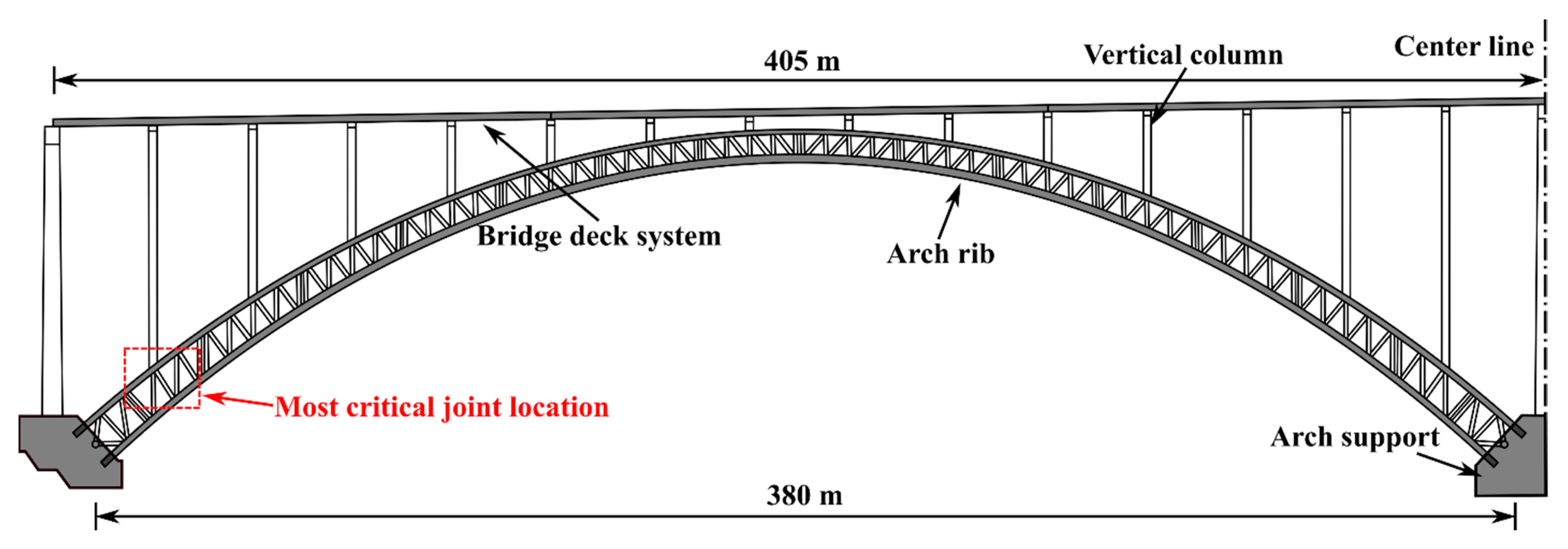
A typical application of a deck CFST arch bridge in China, namely Shuangbao Bridge, was selected as the research object, and an overview of this bridge is introduced in Section 5. The FEM for the most critical joint between the vertical column and the CFST arch rib was developed using the commercial software ABAQUS, as presented in Figure 4. For the CFST arch rib, the circular hollow section had a diameter of 1400 mm and a thickness of 35 mm. For the vertical column, the steel-box section had dimensions of 2200 mm × 1000 mm, while the thicknesses were 16 mm and 22 mm in the x and z directions, respectively. To eliminate the stress concentration due to the Saint-Venant principle, the length of the arch rib was assumed to be 15 times the arch rib’s diameter. Additionally, since the deformation of the vertical column was too small to be considered, it was employed as a rigid body with a height of 100 mm. As the load transfer was evaluated for the serviceability limit state, linear elastic material properties were assigned for both the steel and the concrete. The steel for the arch rib and vertical column had an elastic modulus Es of 2.06 × 10⁵ MPa and a Poisson’s ratio of 0.31. The grade-C70 concrete specified in GB50010-2010 [44] was filled in the arch rib. The elastic modulus Ec and Poisson’s ratio vc were 3.7 × 10⁴ MPa and 0.2, respectively. The vertical column, steel tube, and concrete core were simulated using C3D8 solid elements measuring 50 mm.
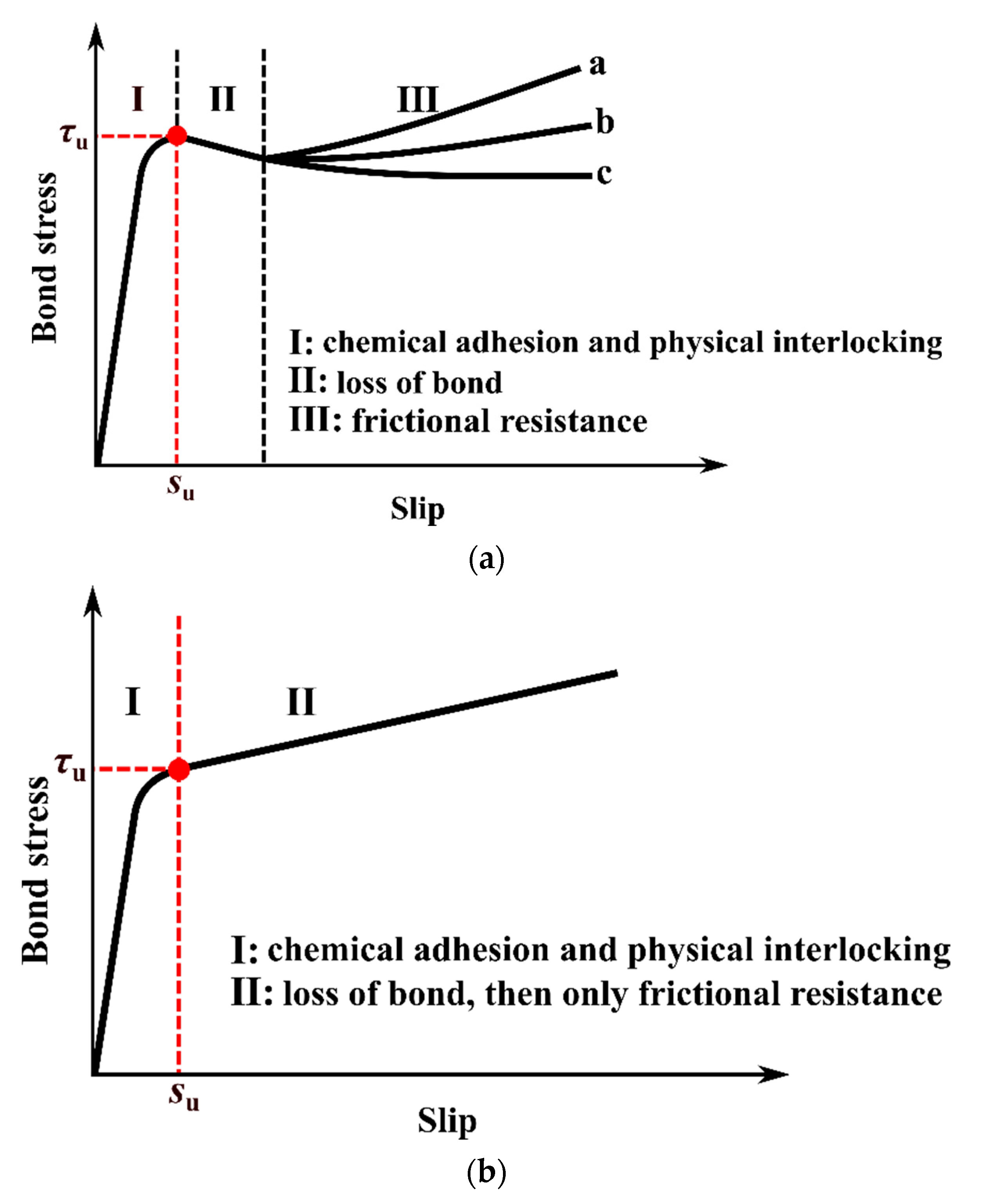
The bond at the steel–concrete interface is the key point in the accurate evaluation of the load-transfer mechanism. As shown in Figure 1, a relatively large difference was found between the bond stress–slip curves. To ensure the safety of the design, the most conservative curve of c (see 
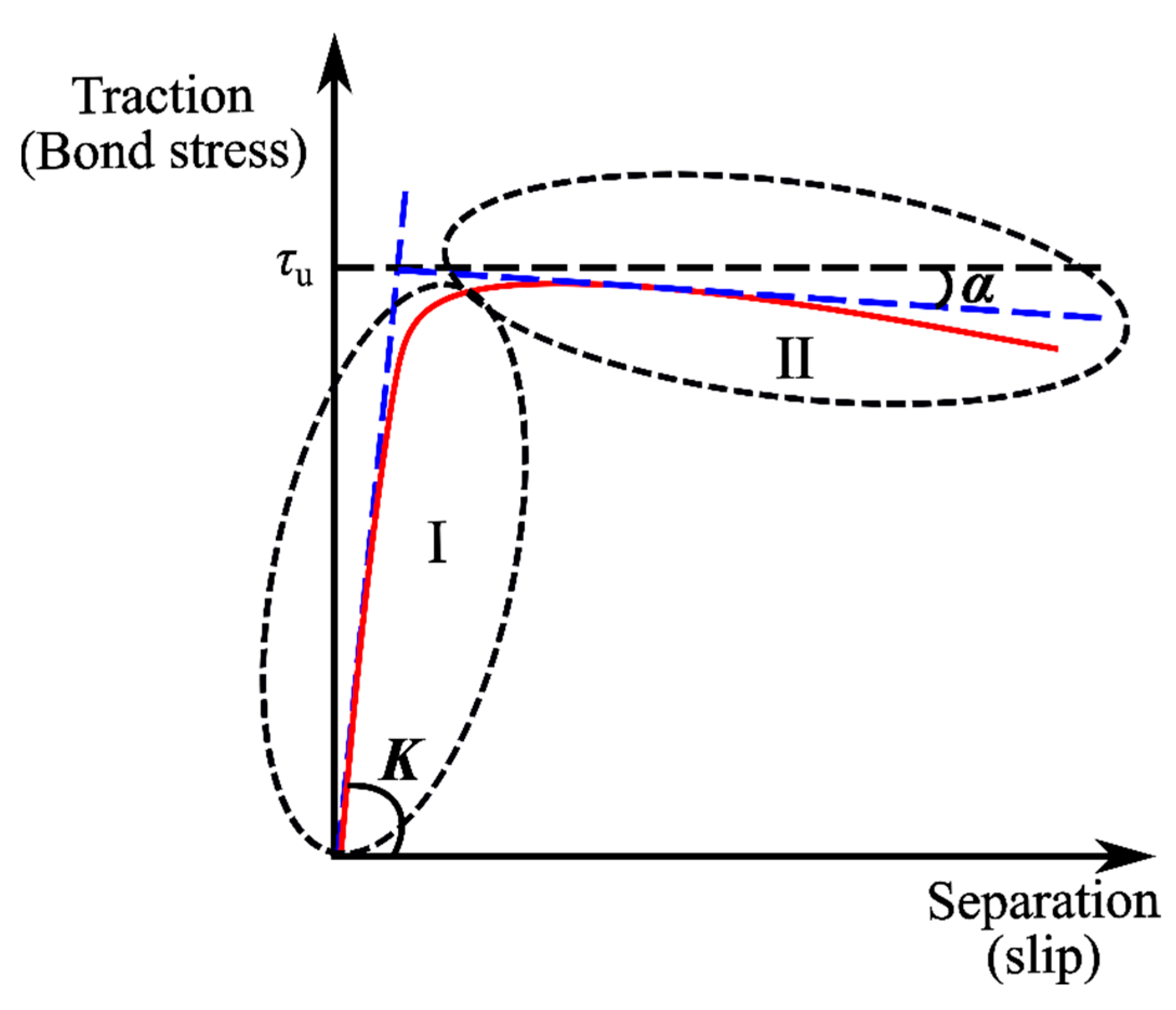
Figure 1a) was assigned in the FEM. The surface-based cohesive contact with the traction-separation model available in the ABAQUS library was assigned, as illustrated in Figure 5. This model assumed a linear bond behavior with a constant shear modulus K prior to the bond strength τu, which was defined as stage I. Once the maximum bond stress was reached, this was regarded as the loss of the bond, while the damage criterion was met based on a user-defined damage-evolution law [13]. After the peak point, the curve decreased with a slope of α.
For stage I, an elastic constitutive matrix, expressed in Equation (14), was adopted to illustrate the relationship between the normal (τn) and tangential (τs, τt) stresses (tractions) and the normal (δn) and tangential (δs, 
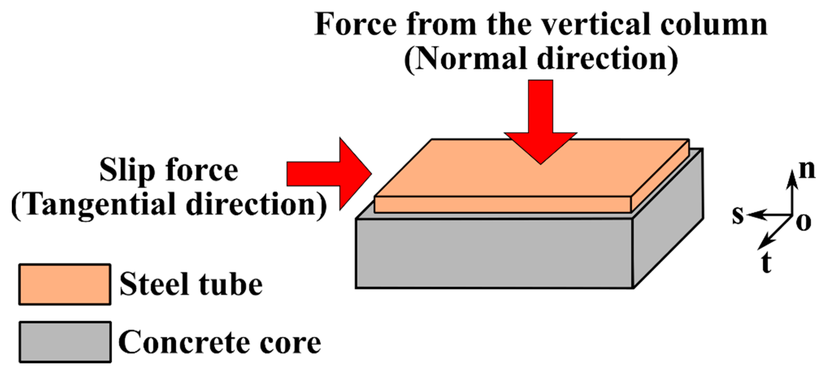
δt) slips at the steel–concrete interface. It was assumed that the bond stresses in three principal directions (see Figure 6) at the steel–concrete interface were uncoupled.
τ n τ s τ t = k nn 0 0 0 k ss 0 0 0 k tt δ n δ s δ t
where knn, kss, and ktt are the initial stiffnesses in the n, s, and t directions, respectively, taken as knn = kss = ktt = 500 N/mm3, in accordance with [7].
The loss of the bond was considered when the following maximum-stress criterion was reached:
max τ n τ n o , τ s τ s o , τ t τ t o = 1
where τ n o is the bond strength in the normal direction, taken as 0.6 MPa, in accordance with [13]; τ s o and τ t o are the bond strengths in the two tangential directions, which can be conservatively taken as the minimum design value of the bond strength of 0.23 MPa specified in DBJ/T13-51-2010, as listed in Table 2.
The hard-contact behavior in ABAQUS was employed to the steel–concrete interface in the normal direction, which means that only separation from each other was allowed. For stage II, the value of α was taken as -0.014, as recommended by [13]. For the boundary conditions, fixed support (Ux = Uy = Uz = URx = URy = URz = 0) and pin support (Uy = Uz = 0) were employed to ends A and B, respectively. According to the numerical analysis of the whole bridge based on the software Midas Civil, the shear force at the joint (ΔV) of 2249 kN and the axial force on the CFST arch rib (Nx) of 24,888 kN under the most unfavorable loading conditions were derived and applied to the FEM in Figure 4. The FEM in this section was developed and validated according to [13].

3.3. Discussion on the FEM Results

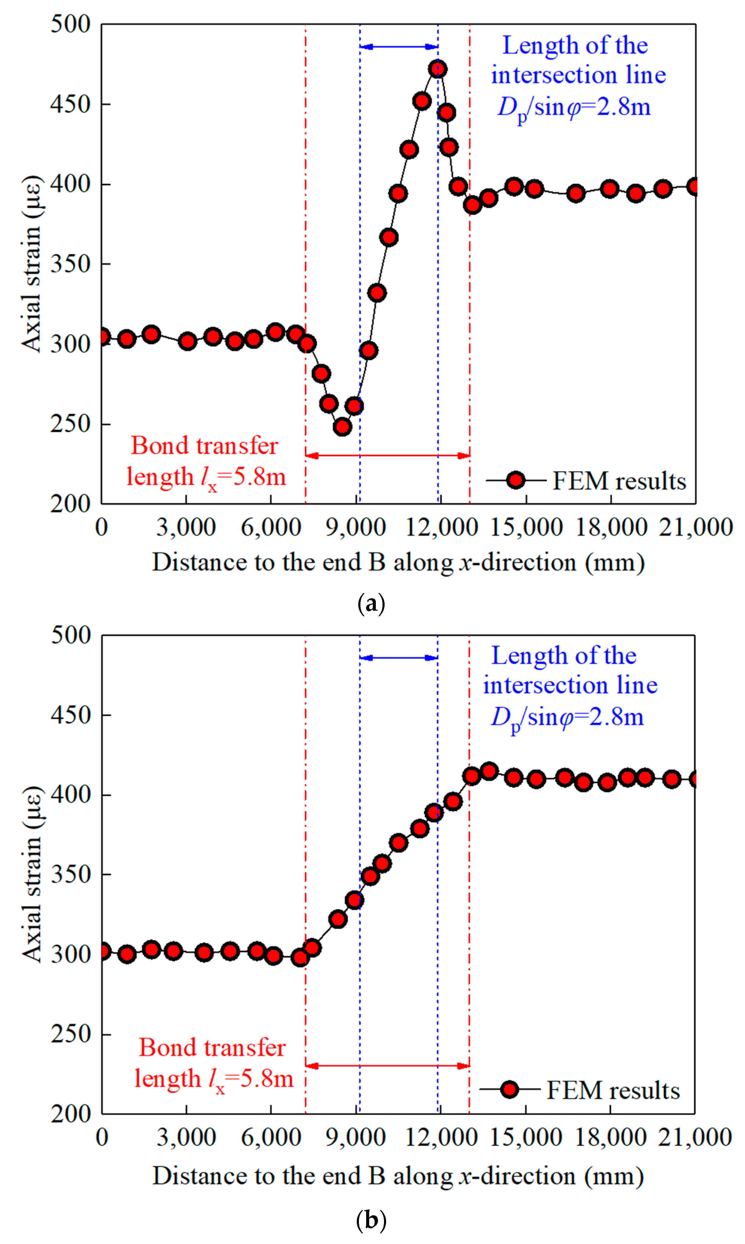
Figure 7 shows the FEM results for the axial strain in the x-direction. It can be observed that the FEM results generally coincided with the analytical results, as shown in Figure 2. For the right side of the vertical column, the same calculated compressive strains of 300 με were found for both the steel tube and the concrete core, which indicated that they worked together to resist the axial force, Nx. Furthermore, it was found that the bond-transfer length of 5.8 m was greater than the length of the intersection line, of 2.8 m, which demonstrated that the load transfer initiated at the location above the joint. Taking account of the bond stress, the compressive strain of the steel tube initially decreased and then increased, because the superposed compressive force was directly applied to the outer surface of the steel tube. For the location away from the joint, the compressive strain of the steel tube decreased and then tended to be a specific value. For the concrete core, the compressive strain increased due to the bond stress and then tended to be a specific value. It also should be noted that the region of the load introduction had symmetric distances above and below the joint. This conclusion can also be found in Figure 8.
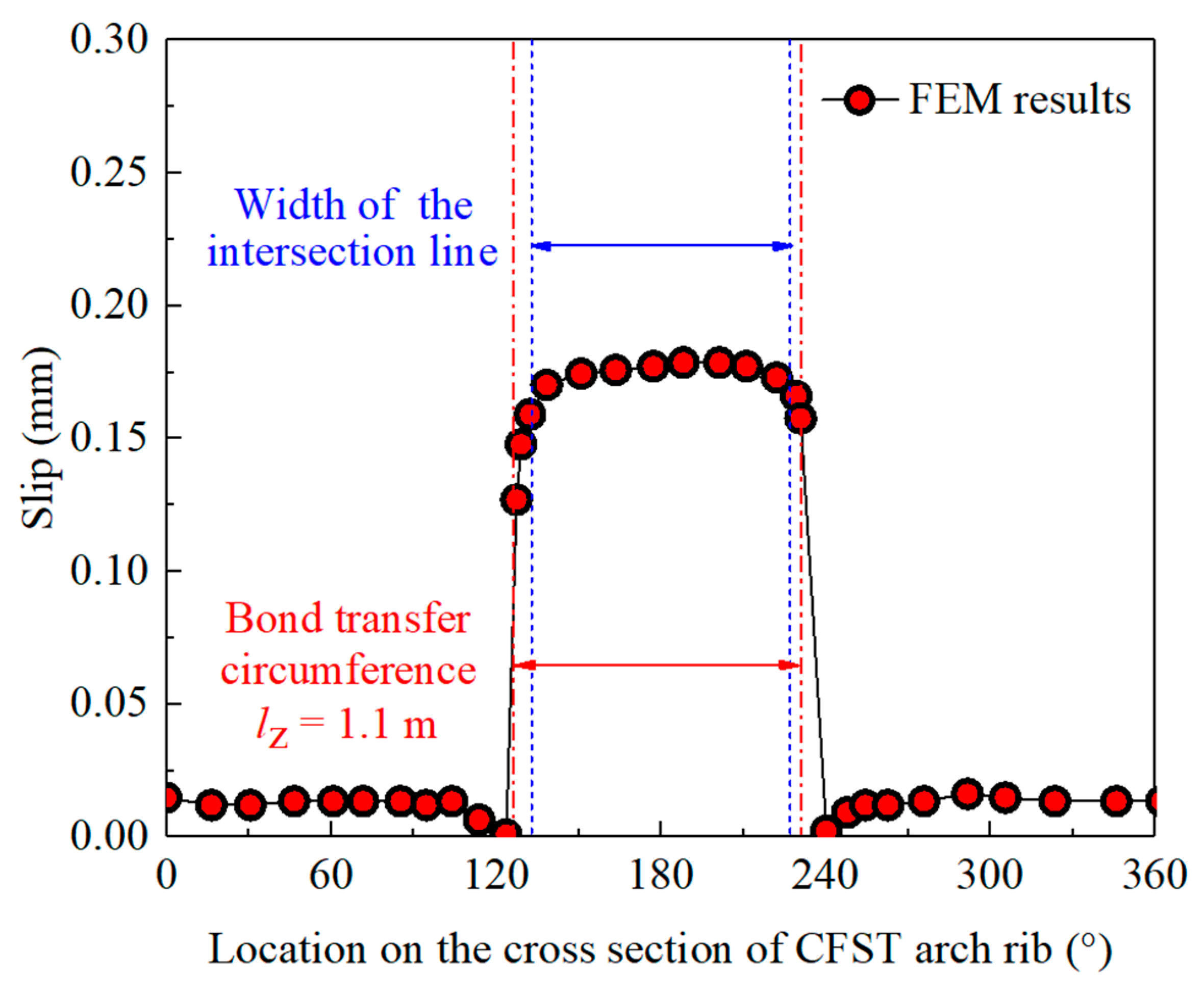
Figure 9 shows the FEM results for the steel–concrete interface slip along the middle section of the CFST arch rib, where the abscissa indicates the location on the cross-section of the CFST arch rib, as shown in Figure 4. It can be observed that the calculated bond-transfer circumference was 1.1 m, which was approximately equal to the width of the intersection area. Therefore, the bond-transfer circumference lz was assumed as the width of the intersection area.
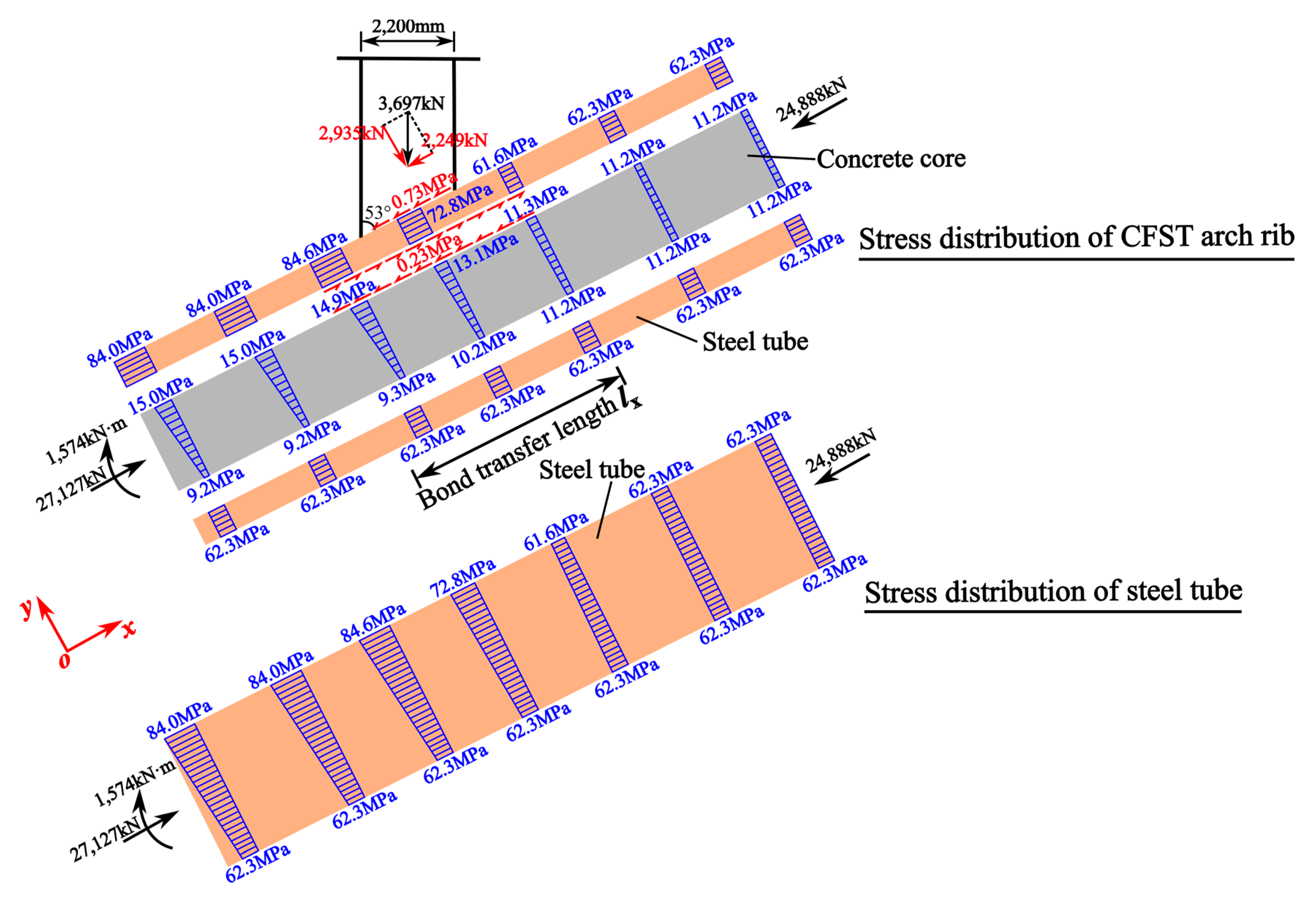
Through Equations (1)–(13), the force–equilibrium relationship for the load transfer in the typical joint in Shuangbao Bridge was obtained, as depicted in Figure 10. Based on the known parameters τd = 0.23 MPa and lz = 1.1 m, the bond-transfer length can be calculated according to Equations (4)–(6).
l x = Δ V c τ d l z = 1405 × 10 3 0.23 × 1.1 × 10 3 = 5 . 6   m
According to Equation (16), the theoretical bond-transfer length was 5.6 m, which essentially coincided with the FEM result of 5.8 m. This indicated that the load-transfer model in Figure 2 can effectively predict the practical situations.

4. Research on the Structural Details of Perfobond-Rib-Shear-Connectors in CFST Arch-Rib Joints

4.1. Geometrical Parameters of the Perfobond-Rib-Shear Connectors

Through properly attaching perfobond-rib-shear connectors to the inner surfaces of CFST arch ribs, the bond-transfer length can be reduced, and the bond behavior can be easily guaranteed. Figure 11 illustrates the geometrical parameters of the perfobond-rib-shear connectors, including the connector length lp, the connector height hp, the connector thickness tp, the connector-hole diameter dp, and the distance between the connector holes yp. Figure 12 presents the arrangement of the perfobond-rib-shear connectors along the cross-section of the CFST arch ribs. Three types of arrangement along the cross-section should be addressed, according to the width of the intersection area, as follows: (a) the uniform arrangement along the whole cross-section, (b) the uniform arrangement along the upper half of the cross-section, and (c) the uniform arrangement along the width of the intersection area. Figure 13 depicts the arrangement of the perfobond-rib-shear connectors along the longitudinal section of the CFST arch ribs. Furthermore, two types of arrangement along the longitudinal section should be addressed, according to the region of the load introduction, as follows: (a) the symmetric arrangement above and below the joint and (b) the asymmetric arrangement above and below the joint.

4.2. Design Principles for the Parameters of Perfobond-Rib-Shear Connectors

Table 3 summarizes the design principles of the parameters of the perfobond-rib-shear connectors. Some of the parameter-design principles were influenced by a single factor; for example, the determination of the connector length was only influenced by the efficiency of the load transfer. However, the principles behind the other parameters were influenced by several factors, such as the connector height, which was itself comprehensively influenced by the efficiency of the load transfer, stiffening action, and constructability.
Similar to the steel–concrete interface, perfobond-rib-shear connectors can perform load transfer through the bond stress. It has been found that the typical bond stress–slip curve for a perfobond-rib-shear connector can be divided into three stages, which are the elastic, plastic, and hardening stages, while a continuous shear resistance can be provided after the bond strength is reached, leading to better ductility compared to the steel–concrete interface [45]. Liao [46] conducted push-out tests on perfobond-rib-shear connectors arranged in CFST columns and pointed out that the elastic stage of the bond stress–slip curve was too short, with a slip of less than 1 mm; furthermore, the shear modulus was in the range of 0.5–1.0 MPa, which was much larger than the shear modulus of the scenario without a perfobond rib shear connector of 0.165 MPa. Liao concluded that the perfobond-rib-shear connector reached the bond strength before the steel–concrete interface. Hence, it can be assumed that the shear force applied to the steel tube is transferred to the concrete core thoroughly by the perfobond-rib-shear connector. To date, many researchers have carried out push-out tests on perfobond-rib-shear connectors and proposed different equations to predict the shear capacity, as summarized in Table 4 [47,48,49,50,51,52,53,54,55,56,57]. In particular, some studies focused on the application of perfobond-rib-shear connectors in steel–concrete-composite bridges; thus, the contribution of transverse rebars in rib holes was taken into account. For perfobond-rib-shear connectors used in CFST arch ribs, only equations that do not consider the contribution of transverse rebars in rib holes can be used to predict the shear capacity, such as those proposed by Leonhardt et al. [47], Hosaka et al. [48], and Zhao et al. [49]. The conversion relationship between the cylinder’s compressive concrete strength fc’ and the prism’s compressive concrete strength fc should be noted. The most conservative of the three equations described above, proposed by Leonhardt et al. [47], was adopted to predict the shear capacity of the perfobond-rib-shear connectors in this paper to address design-safety concerns. Additionally, the connector-hole diameter dp, which is related to the connector height hp, is an unknown value in the equation. As recommended by Cheng [58], an appropriate dp should be taken as 0.5 hp ~ 0.6 hp to make full use of the material.
Regarding the shear strength per hole, Vhole, the connector length, lp, can be determined based on the distance between the connector holes, yp. The minimum connector length lpmin should be determined to completely transfer the shear force applied to the concrete core ΔVc, as follows:
l pmin c e i l Δ V c n p V hole × y p
where the ceil() function computes the nearest integer to a greater extent than the argument passed, and np is the number of perfobond-rib-shear connectors.
As pointed out by Tomii [59], the lateral deformation of the concrete core caught up with that of the steel tube when a certain longitudinal strain was reached, and this was considered the initiation of the confinement effect. At this stage, the concrete core was under triaxial compression, and the steel tube was under longitudinal compression and hoop tension. This stage was usually observed after the yield of the steel tube was in compliance with the von Mises yield criterion. As the force increased, the allowable hoop tension increased, and the allowable longitudinal compression continuously decreased, as shown in Figure 14. Under ideal conditions, point A was reached as the hoop stress reached the yield strength fy and the longitudinal stress reached 0, as shown in Figure 15. At this point, the steel tube could not bear the longitudinal force; thus, the shear force ΔV in the longitudinal direction was transferred completely through the perfobond-rib-shear connector. The design value of the connector length lpd is expressed as follows:
l pd c e i l Δ V n p V hole × y p
According to the above analysis, the efficiency of the load transfer for the perfobond-rib-shear connector was related to the parameters lp, hp, dp, and yp. Among these, the determination of yp was influenced by the reduction due to the rib-hole group, which meant that too small a distance between the connector holes would significantly reduce the shear strength. As recommended in [51,58], an appropriate yp should be taken as 2–3 times the connector-hole diameter dp.
In order to prevent the local buckling of the steel tube, the diameter-to-thickness ratio of CFST arch ribs should be in the range of 35–100, as recommended by GB 50923-2013. In addition, according to JTG/T D65-06-2015, the diameter-to-thickness ratio should be in the range of 24–90. Therefore, the stiffening action of the perfobond rib should be considered for a diameter-to-thickness ratio of greater than 90. According to the numerical analysis in Section 3.3, the bond-transfer circumference is equal to the width of the intersection line; thus, the arrangement of perfobond-rib-shear connectors along the cross-section of CFST arch ribs shown in Figure 12c should be selected. Additionally, the region of the load introduction had symmetric distances above and below the joint; thus, the arrangement of perfobond-rib-shear connectors along the longitudinal section of the CFST arch ribs in Figure 13a should be selected. Meanwhile, the circular steel tube is made by rolling, and therefore, a certain space is needed to weld the perfobond ribs to the inner surface of the steel tube. In practical applications, it is suggested to arrange the perfobond ribs in a circular steel tube with a diameter greater than 800 mm. For the use of more than one perfobond rib along the cross-section, a constructability analysis of the connector height and gap should be conducted.

4.3. Design Flow for the CFST Arch-Rib Joint with PerfobondRib Shear Connectors

Figure 16 presents the design flow for the CFST arch joint with perfobond-rib-shear connectors, including the selection of the geometrical parameters, the arrangement along the cross-section, and the longitudinal section of the CFST arch ribs. The details of the design flow are as follows:
  • For the purpose of the design, the most critical joint is selected, and the corresponding shear force ΔV under the most unfavorable loading is determined.
  • The diameter-to-thickness ratio is checked. If it is greater than 90, the stiffness of the perfobond ribs should be verified to prevent the local buckling of the steel tube; otherwise, no additional stiffeners should be set. According to the above principle, the connector height hp and the connector thickness tp are determined.
  • The connector-hole diameter dp should be taken as 0.5 hp–0.6 hp. Subsequently, the distance between the connector holes yp should be taken as 2 dp–3 dp.
  • The perfobond ribs should be uniformly arranged in the range of the bond-transfer circumference lz along the cross-section. Hence, the number of perfobond ribs np and the gap between them sp can be preliminarily determined. A constructability analysis should be conducted to adjust the parameters hp, np, and sp.
  • The design value of the connector length lpd is determined according to Equation (18), and the perfobond ribs should be arranged in the range of lpd, with the symmetric distance above and below the joint along the longitudinal section.

5. Optimization of the Joints in Shuangbao Bridge

5.1. Overview of Shuangbao Bridge

Shuangbao Bridge is a double-jointed deck CFST arch bridge with an overall span of 2 × 405 m. Figure 17 shows the elevation of one span of Shuangbao Bridge. This bridge has a calculated span of 380 m and a rise of 80 m, leading to a rise–span ratio of 1/4.75. The catenary curve was designed for the main trussed arch with an arch-axis coefficient of 1.55. The space truss was used for the arch rib with heights ranging from 11.0 m in the arch support to 6.5 m at the top of the arch.
The FEM of the whole bridge was developed using the commercial software Midas Civil, and the most critical joint was determined, as shown in Figure 17. Figure 18 illustrates the original design scheme of the joint between the vertical column and the CFST arch rib. The arch rib was designed as the truss structure, consisting of four CFST members. The chord has a diameter of 1400 mm and a thickness of 35 mm, while the vertical and diagonal braces have diameters of 700 mm and thicknesses of 16 mm. A box section of 2200 mm × 1000 mm was adopted for the vertical column. Furthermore, Q390D- and Q355D-grade steels are used for the arch rib and vertical columns, respectively. The arch rib is filled with concrete of grade C70. A steel inclined leg is arranged on the base of the vertical columns, with a projected length lb of 4823.8 mm. The intersection line between the two braces and bottom chord (lc) is 1593.8 mm. In order to enhance the bond strength, a series of welded studs is arranged with a gap of 150 mm along the arch-rib axis for a total length of lb (lc) + 600 mm. In addition, a total of 25 welded studs are arranged with an angular spacing of 14.4° along the cross-section. For the most critical joint, 37 rows (ns) of welded studs, which number 925 in total, are arranged in the top chord over the layout length of 5400 mm. In total, 16 rows (ns) of welded studs, which number 400 in total, are arranged in the bottom chord over the layout length of 2250 mm. The dimensions of the welded studs are ML15 Φ16 × 150.

5.2. Optimization of the Design of the Joint

Using the original design scheme of the joint, fabrication is a complicated process because of the use of such a large number of welded studs. On the other hand, the welded stud only works as a shear connector instead of a stiffener. For these reasons, it is suggested to optimize the design scheme of the joint in both the top and bottom chords of the CFST arch rib by replacing the welded studs with perfobond ribs.
According to the design flow chart (see Figure 16), it can be calculated that the diameter-to-thickness ratio at the most critical joint in Shuangbao Bridge is 40, which is smaller than 90. This indicates that there is no need to check the stiffness of the perfobond rib, and, thus, the height hp and the thickness tp are 200 mm and 16 mm, respectively. Hence, the connector-hole diameter dp and the distance between the connector holes yp are taken as 100 mm and 250 mm, which are 0.5 hp and 2.5 dp, respectively. For the joint in the top chord of the CFST arch rib, a total of five perfobond ribs were designed to be uniformly arranged on the top face of the steel tube over the length of the intersection line (l1 = 1114 mm) at an angular spacing of 23.5°, while a total of three perfobond ribs were designed to be uniformly arranged on the bottom face of the steel tube along the length of the intersection line (l2 = 733 mm) at an angular spacing of 23.5°. Furthermore, the perfobond rib was arranged on the top and bottom faces of the bottom chord in the same way. A constructability analysis was conducted based on the optimized design scheme, which showed the minimum gap between the perfobond ribs in the cross-section is 191 mm. This is greater than the original design scheme of 129 mm, indicating sufficient constructability.
According to Equation (18), the design value of the connector length lpd for the top face of the top chord is:
l pd c e i l Δ V n p V hole × y p = c e i l 2249 × 1000 5 × 1.4 × 30.5 × 100 2 × 250 = 500   mm
The design values of the connector length lpd for the bottom face of the top chord and the top and bottom faces of the bottom chord are:
l pd c e i l Δ V n p V hole × y p = c e i l 2249 × 1000 3 × 1.4 × 30.5 × 100 2 × 250 = 500   mm
where the concrete strength is taken as the design value of the axial compressive strength of 30.5 MPa.
In Section 3.3, it was demonstrated that the bond-transfer length was 5600 mm for the top face of the top chord. According to the result of Equation (18), the bond-transfer length was only 500 mm after arranging the perfobond rib, as shown in Figure 19. For the top face of the top chord, the layout length of the perfobond rib was taken as 5250 mm in consideration of the inclined steel leg. For the other faces, the layout length of the perfobond rib was taken as 2000 mm.

5.3. Comparison between the Original and Optimized Design Schemes of the Joint

Table 5 lists the comparison between the original and optimized design schemes of the joint. According to the FEM results in Section 3.3, the bond-transfer circumference was equal to the width of the intersection line; thus, it was deemed that only welded studs arranged in this region can work. The numbers of welded studs along l1 and l2 (see Figure 18) are listed in Table 5. As recommended by JTG/T D64-01-2015 [60], the shear capacity of the single welded stud can be determined by Equation (21). Additionally, some studies have indicated that a reduction of 0.67–0.98 should be considered for the shear capacity due to the welded studs’ group arrangement. In this paper, a conservative reduction value of 0.67 is taken.
V stud = min 0.43 A stud E c f cd , 0.7 A stud f su
where Vstud is the shear capacity of the single welded stud; Astud is the area of the welded stud rod; fcd is the design value of the axial compressive strength for concrete; fsu is the tensile strength of the welded stud.
As shown in Table 5, the numbers of welded studs arranged at locations ①–④ were 296, 148, 96, and 96, respectively. Correspondingly, the numbers of perfobond ribs arranged at locations ①–④ were 5, 3, 3, and 3, respectively. The layout lengths for these locations in the original design scheme are 5400 mm, 5400 mm, 2250 mm, and 2250 mm, respectively. The layout lengths for these locations in the optimized design scheme are 5250 mm, 2000 mm, 2000 mm, and 2000 mm. It was found that the layout lengths of the perfobond ribs were similar with those of the welded studs, except at location ②. On this basis, a comparison between the steel consumption and shear resistance was made. The shear-resistance ratios of the perfobond ribs (VP) to the welded studs (VS) were 4.02, 1.84, 2.83, and 2.83 for locations ①–④, respectively, while the steel consumptions of the perfobond ribs (QP) and welded studs (QS) were 1.10 tons and 0.17 tons, respectively. Although an increase in the steel consumption of the perfobond ribs compared to that of the welded studs was found, a significant increase of 1.84~4.02 was also observed for the shear resistance of the perfobond ribs compared to the welded studs. It can be concluded that the optimized design scheme had the most efficient load-transfer efficiency. Furthermore, the perfobond ribs were more convenient for the fabrication than the welded studs.

6. Conclusions

This paper studied the mechanism of the load transfer for the novel joints between vertical columns and CFST arch ribs with perfobond-rib-shear connectors. The typical parameters, including the geometric dimensions of the perfobond rib and the arrangements of the perfobond rib along the cross-section and longitudinal section of the arch rib, were evaluated. A design flow for the CFST arch-rib joint with perfobond-rib-shear connectors was proposed. The optimization of the joints in Shuangbao Bridge by replacing welded studs with perfobond ribs was conducted. Based on these investigations, the following conclusions may be drawn:
  • The force–equilibrium relationship for the load transfer at the joint between the vertical columns and the CFST arch ribs was determined. In particular, the design value of the bond strength was taken as 0.23 MPa, as specified in DBJ/T13-51-2010. The shear stress applied to the top face of the steel tube was transferred to the top face of the concrete core through the steel–concrete interface with an arc area. The arc area of the contact surface had symmetric distances above and below the joint in the x-direction. Additionally, the bond-transfer circumference was equal to the width of the intersection area.
  • For the geometric dimensions of the perfobond ribs, the following key factors should be considered: the efficiency of the load transfer, reduction due to the rib holes group, stiffening action, bond-transfer circumference, region of the load transfer, and constructability. The perfobond ribs should be uniformly arranged over the width of the intersection area along the cross-section and symmetrically arranged above and below the joint along the longitudinal section.
  • Significant increases in shear resistance, by factors of 1.84–4.02, were found for the perfobond ribs compared to the welded studs. It can be concluded that the optimized design scheme had the most efficient load transfer. Furthermore, the perfobond rib was more convenient for the fabrication than the welded stud.

Author Contributions

Conceptualization, Y.L.; methodology, Y.L.; software, Y.Z. and Y.G.; validation, J.L.; formal analysis, J.L.; investigation, L.J.; resources, J.X. and H.L.; data curation, L.J.; writing—original draft preparation, L.J.; writing—review and editing, J.L.; visualization, Y.Z. and Y.G.; supervision, Y.L.; project administration, J.X. and H.L.; funding acquisition, L.J. All authors have read and agreed to the published version of the manuscript.

Funding

This research was funded by the National Natural Science Foundation of China (grant no. 52008026), Overseas Students Science and Technology Activities Project Merit Funding in Shaanxi Province (grant no. 2021-11), China Postdoctoral Science Foundation (grant no. 2021M692746), and Natural Science Basic Research Program of Shaanxi (grant no. 2021JQ-272).

Data Availability Statement

Not applicable.

Acknowledgments

Special thanks to the School of Highway, Chang’an University, for critiquing the manuscript and providing constructive feedback.

Conflicts of Interest

The authors declare no conflicts interest.

Notations

Accross-sectional area of the concrete core;
Acclongitudinal concrete shear area per connector;
ApTop-face area of the steel tube within the length of the intersection line, between vertical column and CFST arch rib;
ATarea of the contact surface;
Atrarea of the transverse rebars in rib holes;
Ascross-sectional area of the steel tube;
Astudarea of the welded stud rod;
bcthickness of the concrete slab;
bfwidth of the steel-beam flange;
Ddiameter of the steel tube;
Dpheight of the cross-section of the vertical column;
dpconnector-hole diameter;
dtrdiameter of the transverse rebar;
Δddistance to the right end of the intersection line in the x-direction;
Ecelastic modulus of the concrete;
Eselastic modulus of the steel;
fcprism compressive concrete strength;
fc’cylinder compressive concrete strength;
fcddesign value of the axial compressive strength for concrete;
fttensile concrete strength;
fsutensile strength of the welded stud;
fyyield of the transverse rebar;
Hheight of the concrete core;
hfdistance between the end of the perfobond rib and the end of the concrete slab;
hpconnector height;
Kshear modulus;
knn, kss, kttinitial stiffnesses in the n, s, and t directions, respectively;
Llength of the CFST column;
Lccontact length between the concrete slab and the steel-beam flange;
lbprojected length of the steel inclined leg arranged at the base of the vertical column;
lcthe length of the intersection line between two braces and bottom chord;
lpconnector length;
lpminminimum connector length;
lpddesign value of the connector length;
lPlayout lengths of perfobond ribs;
lSlayout lengths of welded studs;
lwarc width of the cross-section of the vertical column;
lxBond-transfer length;
Δlxdistance of an assumed segment;
lzbond-transfer circumference;
Nvertical load applied to vertical column;
Nxaxial force applied to the CFST arch rib transferred from the vertical column;
ΔNvertical force component of N;
nconnector-hole number;
npperfobond-rib-shear-connector number;
nsthe number of the row of welded studs;
QPsteel consumption of perfobond ribs;
QSsteel consumption of welded studs;
spgap between perfobond-rib-shear connectors;
Tthickness of the steel tube;
tpconnector thickness;
Vholeshear capacity per hole;
VPshear resistance of perfobond ribs;
VPBLshear capacity per connector;
VSshear resistance of welded studs;
Vstudshear capacity of the single welded stud;
ΔVHorizontal-force component of N;
ΔVchorizontal force applied to the concrete;
vshear stress on the top face of the steel tube;
vcPoisson’s ratio of the concrete;
vsPoisson’s ratio of the steel;
ypdistance between connector holes;
σc1compressive stress on the concrete core in cross-section ①;
σc2tcompressive stress on the top face of the concrete core in cross-section ②;
σc2bcompressive stress on the bottom face of the concrete core in cross-section ②;
σc5tcompressive stress on the top face of the concrete core in cross-section ⑤;
σc5bcompressive stress on the bottom face of the concrete core in cross-section ⑤;
σs1compressive stress on the steel tube in cross-section ①;
σs3compressive stress on the steel tube in cross-section ③;
σs5compressive stress on the steel tube in cross-section ⑤;
αslope for the traction-separation model after the peak point;
δnnormal slip;
δs, δttangential slip;
τddesign value of the bond strength;
τubond strength;
τnnormal traction;
τs, τttangential traction;
τnobond strength in the normal direction;
τso, τtobond strength in two tangential directions;
φangle between the vertical column and CFST arch rib.

References

  1. Zheng, J.; Wang, J. Concrete-filled steel tube arch bridges in China. Engineering 2018, 4, 143–155. [Google Scholar] [CrossRef]
  2. Chen, B.; Wang, T.L. Overview of concrete filled steel tube arch bridges in China. Pract. Period. Struct. Des. Constr. 2009, 14, 70–80. [Google Scholar] [CrossRef]
  3. Zhang, W.; Wang, R.; Zhao, H.; Lam, D.; Chen, P. Axial-load response of CFST stub columns with external stainless steel and recycled aggregate concrete: Testing, mechanism analysis and design. Eng. Struct. 2022, 256, 113968. [Google Scholar] [CrossRef]
  4. Lai, M.H.; Song, W.; Ou, X.L.; Chen, M.T.; Wang, Q.; Ho, J. A path dependent stress-strain model for concrete-filled-steel-tube column. Eng. Struct. 2020, 211, 110312. [Google Scholar] [CrossRef]
  5. Gao, W.; Zhao, J.; Fan, J.; You, H.; Wang, Z. A theoretical model for predicting mechanical properties of circular concrete-filled steel tube short columns. Structures 2022, 45, 572–585. [Google Scholar] [CrossRef]
  6. Lai, Z.; Jiang, H.; Cai, Y. A new design equation to estimate the axial compressive strength of circular concrete-filled steel tubular stub columns. Structures 2022, 46, 1043–1054. [Google Scholar] [CrossRef]
  7. Wang, F.; Xie, W.; Li, B.; Han, L. Experimental study and design of bond behavior in concrete-filled steel tubes (CFST). Eng. Struct. 2022, 268, 114750. [Google Scholar] [CrossRef]
  8. Dong, H.; Chen, X.; Cao, W.; Zhao, Y. Bond-slip behavior of large high-strength concrete-filled circular steel tubes with different constructions. J. Constr. Steel Res. 2020, 167, 105951. [Google Scholar] [CrossRef]
  9. Naghipour, M.; Khalili, A.; Hasani, S.M.R.; Nematzadeh, M. Experimental investigation of natural bond behavior in circular CFTs. Steel Compos. Struct. 2022, 42, 191–207. [Google Scholar] [CrossRef]
  10. Lin, Y.; Zhao, Z.; Gao, X.; Wang, Z.; Qu, S. Behavior of concrete-filled U-shaped steel beam to CFSST column connections. Buildings 2023, 13, 517. [Google Scholar] [CrossRef]
  11. Luo, J.; Gao, S.; Zhang, Y.; Guo, X.; Chen, S.; Ding, F. Load-transfer mechanism of distribution beams in giant rectangular concrete-filled steel tubular columns. J. Constr. Steel Res. 2022, 197, 107487. [Google Scholar] [CrossRef]
  12. Ami, M.; Zahrai, S.M. Compressive behavior and design of octagonal rubberized concrete-filled double steel tubular stub columns stiffened by headed studs. Structures 2022, 42, 104–124. [Google Scholar] [CrossRef]
  13. Mollazadeh, M.H.; Wang, Y.C. New insights into the mechanism of load introduction into concrete-filled steel tubular column through shear connection. Eng. Struct. 2014, 75, 139–151. [Google Scholar] [CrossRef]
  14. Mollazadeh, M.H.; Wang, Y.C. New mechanism of load introduction into concrete-filled steel tubular columns. J. Struct. Eng. 2016, 142, 4016016. [Google Scholar] [CrossRef] [Green Version]
  15. Yan, X.; Shi, S.; Liu, X.; Mao, H. Numerical analysis of mechanical behavior of self-centering joint between CFDST column and RC beam. Buildings 2023, 13, 135. [Google Scholar] [CrossRef]
  16. Ramírez Ortiz, C.; Gutierrez Amador, A.D.; Ramírez Duque, J.L. Numerical analysis of the seismic behavior of a steel beam-to-concrete-filled steel tubular column connection using external diaphragms. Buildings 2022, 12, 1217. [Google Scholar] [CrossRef]
  17. Debnath, P.P.; Xu, F.; Chan, T. Load transfer mechanism in concrete-filled steel tubular columns: Developments, challenges and opportunities. J. Constr. Steel Res. 2023, 203, 107781. [Google Scholar] [CrossRef]
  18. Song, S.; Xu, F.; Chen, J.; Wang, Y. Mechanism of load introduction and transfer within steel-encased concrete-filled steel tube connections. J. Constr. Steel Res. 2023, 203, 107818. [Google Scholar] [CrossRef]
  19. Chen, H.; Nie, X.; Gan, S.; Zhao, Y.; Qiu, H. Interfacial imperfection detection for steel-concrete composite structures using NDT techniques: A state-of-the-art review. Eng. Struct. 2021, 245, 112778. [Google Scholar] [CrossRef]
  20. Gong, S.; Feng, X.; Zhang, G.; Ansari, F. Distributed detection of internal cavities in concrete-filled steel tube arch bridge elements. Struct. Health Monit. 2023, 22, 657–671. [Google Scholar] [CrossRef]
  21. Zhou, X.; Liu, Y.; Jiang, L.; Zhang, N. Review on mechanical behavior research of concrete filled rectangular hollow section tube stiffened with PBL. China J. Highw. Transp. 2017, 30, 45–62. (In Chinese) [Google Scholar]
  22. Liu, Y.; Xiong, Z.; Feng, Y.; Jiang, L. Concrete-filled rectangular hollow section X joint with Perfobond Leister rib structural performance study: Ultimate and fatigue experimental Investigation. Steel Compos. Struct. 2017, 24, 455–465. [Google Scholar] [CrossRef]
  23. Jiang, L.; Liu, Y.; Fam, A.; Liu, J.; Liu, B. Stress concentration factor parametric formulae for concrete-filled rectangular hollow section K-joints with perfobond ribs. J. Constr. Steel Res. 2019, 160, 579–597. [Google Scholar] [CrossRef]
  24. Jiang, L.; Liu, Y.; Fam, A. Stress concentration factors in concrete-filled square hollow section joints with perfobond ribs. Eng. Struct. 2019, 181, 165–180. [Google Scholar] [CrossRef]
  25. Jiang, L.; Liu, Y.; Fam, A.; Wang, K. Fatigue behaviour of non-integral Y-joint of concrete-filled rectangular hollow section continuous chord stiffened with perfobond ribs. Eng. Struct. 2019, 191, 611–624. [Google Scholar] [CrossRef]
  26. Jiang, L.; Liu, Y.; Fam, A.; Liu, B.; Long, X. Fatigue behavior of integral built-up box Y-joints between concrete-filled chords with perfobond ribs and hollow braces. J. Struct. Eng. 2020, 146, 4019218. [Google Scholar] [CrossRef]
  27. Jiang, L.; Liu, Y.; Fam, A.; Liu, B.; Pu, B.; Zhao, R. Experimental and numerical analyses on stress concentration factors of concrete-filled welded integral K-joints in steel truss bridges. Thin Wall. Struct. 2023, 183, 110347. [Google Scholar] [CrossRef]
  28. Cheng, G.; Liu, Y.; Li, H.; Zhang, N.; Su, J. Testing and analysis of concrete-filled square hollow section stub columns with perfobond leister rib. Teh. Vjesn. 2019, 26, 1081–1090. [Google Scholar] [CrossRef]
  29. Mollazadeh, M.H. Load Introduction into Concrete-Filled Steel Tubular Columns; The University of Manchester: Manchester, UK, 2015. [Google Scholar]
  30. Virdi, K.S.; Dowling, P.J. Bond strength in concrete filled steel tubes. IABSE Proc. 1980, 4, 125–139. [Google Scholar]
  31. Roeder, C.W.; Cameron, B.; Brown, C.B. Composite action in concrete filled tubes. J. Struct. Eng. 1999, 125, 477–484. [Google Scholar] [CrossRef]
  32. Aly, T.; Elchalakani, M.; Thayalan, P.; Patnaikuni, I. Incremental collapse threshold for pushout resistance of circular concrete filled steel tubular columns. J. Constr. Steel Res. 2010, 66, 11–18. [Google Scholar] [CrossRef]
  33. Tao, Z.; Song, T.; Uy, B.; Han, L. Bond behavior in concrete-filled steel tubes. J. Constr. Steel Res. 2016, 120, 81–93. [Google Scholar] [CrossRef]
  34. Xu, C.; Chengkui, H.; Decheng, J.; Yuancheng, S. Push-out test of pre-stressing concrete filled circular steel tube columns by means of expansive cement. Constr. Build. Mater. 2009, 23, 491–497. [Google Scholar] [CrossRef]
  35. Xue, L.; Cai, S. Bond strength at the interface of concrete-filled steel tube columns, Part I. Build. Sci. 1996, 12, 22–28. (In Chinese) [Google Scholar]
  36. Xue, L.; Cai, S. Bond strength at the interface of concrete-filled steel tube columns, Part II. Build. Sci. 1996, 12, 19–23. (In Chinese) [Google Scholar]
  37. Liu, Y.; Chi, J. Push-out test on shear bond strength of CFST. Ind. Constr. 2006, 36, 78–80. (In Chinese) [Google Scholar]
  38. Liu, Y.; Liu, J.; Chi, J. Shear bond behaviors at interface of concrete-filled steel tube. J. Guangxi Univ. 2010, 35, 17–23. (In Chinese) [Google Scholar]
  39. DBJ/T13-51-2010; Technical Specification for Concrete-Filled Steel Tubular Structures. Department of Housing and Urban-Rural in Fujian Province: Fuzhou, China, 2010.
  40. BS EN 1994-1-1; Eurocode 4: Design of Composite Steel and Concrete Structures—Part 1-1: General Rules and Rules for Buildings. British Standards Institution: London, UK, 2004.
  41. BS 5400-5: 2005; Steel, Concrete and Composite Bridges—Part 5: Code of Practice for the Design of Composite Bridges. British Standards Institution: London, UK, 2005.
  42. AS 5100.6-2004; Bridge Design—Part 6: Steel and Composite Construction. Standards Australia International Ltd.: Sydney, Australia, 2004.
  43. ANSI-AISC 360-05; Specification for Structural Steel Building. American Institute of Steel Construction: Chicago, IL, USA, 2010.
  44. GB50010-2010; Code for Design of Concrete Structures. China Architecture & Building Press: Beijing, China, 2010.
  45. Vianna, J.d.C.; de Andrade, S.; Vellasco, P.C.G.D.; Costa-Neves, L.F. Experimental study of perfobond shear connectors in composite construction. J. Constr. Steel Res. 2013, 81, 62–75. [Google Scholar] [CrossRef]
  46. Liao, C. Experimental Study on the Ultimate Shear Capacity of Grouped Stud Connectors in Continuous Composite Steel-Concrete Girder Bridge; Tongji University: Shanghai, China, 2007. (In Chinese) [Google Scholar]
  47. Leonhardt, F.; Andrae, W.; Andrae, H.; Harre, W. New, improved bonding means for composite load bearing structures with high fatigue strength. Beton-Und Stahlbetonbau 1987, 82, 325–331. [Google Scholar] [CrossRef]
  48. Hosaka, T.; MItsugi, K.; Hiragi, H.; Ushijima, H. Study on shear strength and design method of perfobond strip. Jpn. J. Struct. Eng. 2002, 48, 1265–1272. [Google Scholar]
  49. Xue, W.; Dai, Y.; Zhou, L.; Lu, Y. Experimental studies on shear behavior of perfobond connectors. J. Build. Struct. 2009, 30, 103–111. (In Chinese) [Google Scholar]
  50. Zhao, C.; Liu, Y. Experimental study of shear capacity of perfobond connector. Eng. Mech. 2012, 29, 349–354. (In Chinese) [Google Scholar]
  51. Oguejiofor, E.C.; Hosain, M.U. A parametric study of perfobond rib shear connectors. Can. J. Civ. Eng. 1994, 21, 614–625. [Google Scholar] [CrossRef]
  52. Oguejiofor, E.C.; Hosain, M.U. Numerical analysis of push-out specimens with perfobond rib connectors. Comput. Struct. 1997, 62, 617–624. [Google Scholar] [CrossRef]
  53. Veríssimo, G.S.; Paes, J.R.; Valente, I.; Cruz, P.J.; Fakury, R.H. Design and experimental analysis of a new shear connector for steel and concrete composite structures. In Proceedings of the 3rd International Conference on Bridge Maintenance, Safety, Management, Life-cycle Performance and Cost, Porto, Portugal, 16–19 July 2006; Taylor & Francis: London, UK, 2006. [Google Scholar]
  54. Medberry, S.B.; Shahrooz, B.M. Perfobond shear connector for composite construction. Eng. J. 2002, 39, 2–12. [Google Scholar]
  55. Al-Darzi, S.Y.K.; Chen, A.R.; Liu, Y.Q. Finite element simulation and parametric studies of perfobond rib connector. Am. J. Appl. Sci. 2007, 4, 122–127. [Google Scholar] [CrossRef] [Green Version]
  56. Ahn, J.H.; Lee, C.G.; Won, J.H.; Kim, S.H. Shear resistance of the perfobond-rib shear connector depending on concrete strength and rib arrangement. J. Constr. Steel Res. 2010, 66, 1295–1307. [Google Scholar] [CrossRef]
  57. Zong, Z.; Che, H. Experimental study of shear connector under static and fatigue loading. J. Fuzhou Univ. 1999, 27, 61–66. (In Chinese) [Google Scholar]
  58. Cheng, G. Research on the Mechanism of Rectangular Concrete-Filled Steel Tube Structure Stiffened with PBL; Chang’an University: Xi’an, China, 2015. (In Chinese) [Google Scholar]
  59. Tomii, M. Experimental studies on concrete filled steel tubular stub columns under concentric loading. In Proceedings of the International Colloquium on Stability of Structures under Static and Dynamic Loads, Washington, DC, USA, 17–19 May 1977; SSRC/ASCE: Washington, DC, USA, 1977. [Google Scholar]
  60. JTG/T D64-01-2015; Specifications for Design and Construction of Highway Steel-Concrete Composite Bridge. China Communication Press: Beijing, China, 2015. (In Chinese)
Figure 1. Typical bond stress–slip curves at the steel–concrete interface: (a) the curve with peak point; (b) the curve without peak point.
Buildings 13 00807 g001
Figure 2. Force–equilibrium relationship for the load transfer at the typical joint of the deck CFST arch bridge.
Buildings 13 00807 g002
Figure 3. Segment Δlx of the concrete core.
Buildings 13 00807 g003
Figure 4. The FEM for the joint between the vertical column and CFST arch rib.
Buildings 13 00807 g004
Figure 5. Traction-separation model.
Buildings 13 00807 g005
Figure 6. Definition of the directions at steel–concrete interface.
Buildings 13 00807 g006
Figure 7. The FEM results for the axial strains in the x-direction: (a) steel tube; (b) concrete core.
Buildings 13 00807 g007
Figure 8. The FEM results for the longitudinal slip in the x-direction.
Buildings 13 00807 g008
Figure 9. FEM results for the steel–concrete interface slip along the middle section of the CFST arch rib.
Buildings 13 00807 g009
Figure 10. Force–equilibrium relationship for the load transfer in a typical joint in Shuangbao Bridge.
Buildings 13 00807 g010
Figure 11. Geometrical parameters of the perfobond-rib-shear connectors.
Buildings 13 00807 g011
Figure 12. Arrangement of perfobond-rib-shear connectors along the cross-section of CFST arch ribs: (a) uniform arrangement along the whole cross-section; (b) uniform arrangement along the upper half of the cross-section; (c) uniform arrangement along the width of the intersection area.
Buildings 13 00807 g012
Figure 13. Arrangement of perfobond-rib-shear connectors along the longitudinal section of CFST arch ribs: (a) symmetric arrangement above and below the joint; (b) asymmetric arrangement above and below the joint.
Buildings 13 00807 g013
Figure 14. Yield envelope and stress path of the steel tube.
Buildings 13 00807 g014
Figure 15. Analytical model of the design value of the connector length.
Buildings 13 00807 g015
Figure 16. Design flow chart for the CFST arch rib joint with perfobond rib=shear connectors.
Buildings 13 00807 g016
Figure 17. Elevation of the single span of Shuangbao Bridge.
Buildings 13 00807 g017
Figure 18. Original design scheme of the joint between the vertical column and CFST arch rib: (a) the joint in the top chord of the CFST arch rib; (b) the joint in the bottom chord of the CFST arch rib; (c) the cross-section of the top chord of the CFST arch rib; (d) the cross-section of the bottom chord of the CFST arch rib.
Buildings 13 00807 g018aBuildings 13 00807 g018b
Figure 19. Optimized design scheme of the joint between the vertical column and CFST arch rib: (a) the joint in the top chord of the CFST arch rib; (b) the joint in the bottom chord of the CFST arch rib; (c) the cross-section of the top chord of the CFST arch rib; (d) the cross-section of the bottom chord of the CFST arch rib; (e) dimensions of the perfobond rib.
Buildings 13 00807 g019aBuildings 13 00807 g019b
Table 1. Summary of the push-out-test results for CFST columns.
Ref.Number of SpecimensDimensions (mm)Concrete Strength (Mpa)Bond Strength τu (Mpa)Shear Modulus (Mpa)
DiameterThicknessHeight
Virdi et al. [30]91148.4~3065.6~10.1149.4~463.622.0~46.30.27~3.65/
Roeder et al. [31]20247.6~598.45.6~13.5758.0~1927.027.9~47.30.01~0.79/
Aly et al. [32]7114.33.2450.040.0~80.00.61~1.23/
Tao et al. [33]5120.0~400.03.6~8.0600.0~1200.042.0~55.80.60~1.85/
Xu et al. [34]3150.02.8~4.5500.047.00.60~0.67/
Xue et al. [35,36]32165.05.0300.0~900.041.9~83.70.37~1.03/
Liu et al. [37,38]15115.04.0345.0~632.032.30.93~1.410.165
Table 2. Summary of the bond-behavior models for beam–column joints in buildings, as recommended by design guidelines.
Design GuidelinesDesign Value of the Bond Strength τd (MPa)Bond Transfer Length lx (m)Region of the Load IntroductionBond Transfer Circumference lz (m)
DBJ/T13-51-2010 [39]0.23///
Eurocode 4 [40]0.55min (1/3L, 2D)/πD
BS5400-5 [41]0.40///
AS5100.6-2004 [42]0.40///
ANSI-AISC 360-05 [43]0.404Dsymmetric distances above and below the jointπD/4
Table 3. Design principles for the parameters of perfobond-rib-shear connectors.
FactorsDimensions of Perfobond-Rib-Shear ConnectorsArrangement Along the Cross-SectionArrangement Along the Longitudinal Section
Connector Length lpConnector Height hpConnector Thickness tpConnector-Hole Diameter dpDistance between Connector Holes yp
Efficiency of the load transfer
Reduction due to the rib-hole group
Stiffening action
Bond-transfer circumference
Region of the load introduction
Constructability
Table 4. Equations to predict the shear capacity of perfobond-rib-shear connectors.
TypeReferenceEquationsApplicable Conditions
Shear capacity per holeLeonhardt et al. [47] V hole = 1.4 d p 2 f c without transverse rebars in rib holes
Hosaka et al. [48] V P = 3.38 t p / d p d p 2 f c 39000 without transverse rebars in rib holes
V P = 1.45 d p 2 d tr 2 f c + d s 2 f y 26100 with transverse rebars in rib holes
Xue et al. [49] V P = 2.936 π d p 2 d tr 2 f t + 0.289 π d tr 2 f y with transverse rebars in rib holes
Zhao et al. [50] V P = 1.38 d p 2 f c without transverse rebars in rib holes
V P = 1.38 d p 2 d tr 2 f c + 1.24 d tr 2 f y with transverse rebars in rib holes
Shear capacity per ribOguejiofor et al. [51,52] V P = 0.590 A c c f c + 2.871 n d p 2 f c             + 1.233 A tr f y with transverse rebars in rib holes
V P = 4.50 h P t P f c + 3.31 n d p 2 f c             + 0.91 A tr f y with transverse rebars in rib holes and replacement of splitting resistance of concrete with end-bearing resistance
Veríssimo et al. [53] V P = 4.04 h p / b c h p t p f c + 2.37 n d p 2 f c             + 0.16 A cc f c + 31.85 × 10 6 A tr / A cc with transverse rebars in rib holes
Medberry et al. [54] V P = 0.747 b c h f f c + 0.413 b f L c             + 1.304 n d p 2 f c + 0.9 A tr f y with transverse rebars in rib holes
AI-Darzi et al. [55] V P = 3.97 n d p 2 f c + 0.762 h p t p f c             7.59 × 10 4 A tr f y + 255310 with transverse rebars in rib holes
Ahn et al. [56] V P = 3.14 h p t p f c + 2.98 n d p 2 f c + 1.21 A tr f y single perfobond rib arranged with transverse rebars in rib holes
V P = 2.76 h p t p f c + 2.61 n d p 2 f c + 1.06 A tr f y twin perfobond ribs arranged with transverse rebars in rib holes
Zong et al. [57] V P = 0.0029 A h E c f c + 0.75 A tr f y with transverse rebars in rib holes
Note: Vhole is the shear capacity per hole; VPBL is the shear capacity per connector; fc’ is the cylinder’s compressive concrete strength; dtr is the diameter of the transverse rebar; ft is the tensile concrete strength; fy is the yield strength of the transverse rebar; fc is the prism’s compressive concrete strength; Acc is the longitudinal concrete shear area per connector; n is the connector-hole number; Atr is the area of the transverse rebars in rib holes; bc is the thickness of the concrete slab; hf is the distance between the end of the perfobond rib and the end of the concrete slab; bf is the width of the steel-beam flange; Lc is the contact length between the concrete slab and the steel-beam flange.
Table 5. Comparison between the original and optimized design schemes of the joints.
LocationWelded StudsPerfobond RibsComparisons
NumberLayout Length lS (mm)Shear Resistance vs. (kN)Steel Consumption QS (ton)NumberLayout Length lP (mm)Shear Resistance VP (kN)Steel Consumption QP (ton)lP/lSVP/VSQP/QS
① Top face of the top chord296540011,1660.175525044,8351.100.974.026.47
② Bottom face of the top chord148540055823200010,2480.371.84
③ Top face of the bottom chord96225036213200010,2480.892.83
④ Bottom face of the bottom chord96225036213200010,2480.892.83
Disclaimer/Publisher’s Note: The statements, opinions and data contained in all publications are solely those of the individual author(s) and contributor(s) and not of MDPI and/or the editor(s). MDPI and/or the editor(s) disclaim responsibility for any injury to people or property resulting from any ideas, methods, instructions or products referred to in the content.

