

Numerical Simulation of the Dynamic Responses and Impact-Bearing Capacity of CFDST Columns under Lateral Impact
Abstract
:1. Introduction
2. Numerical Model
2.1. Material Model
2.1.1. Concrete
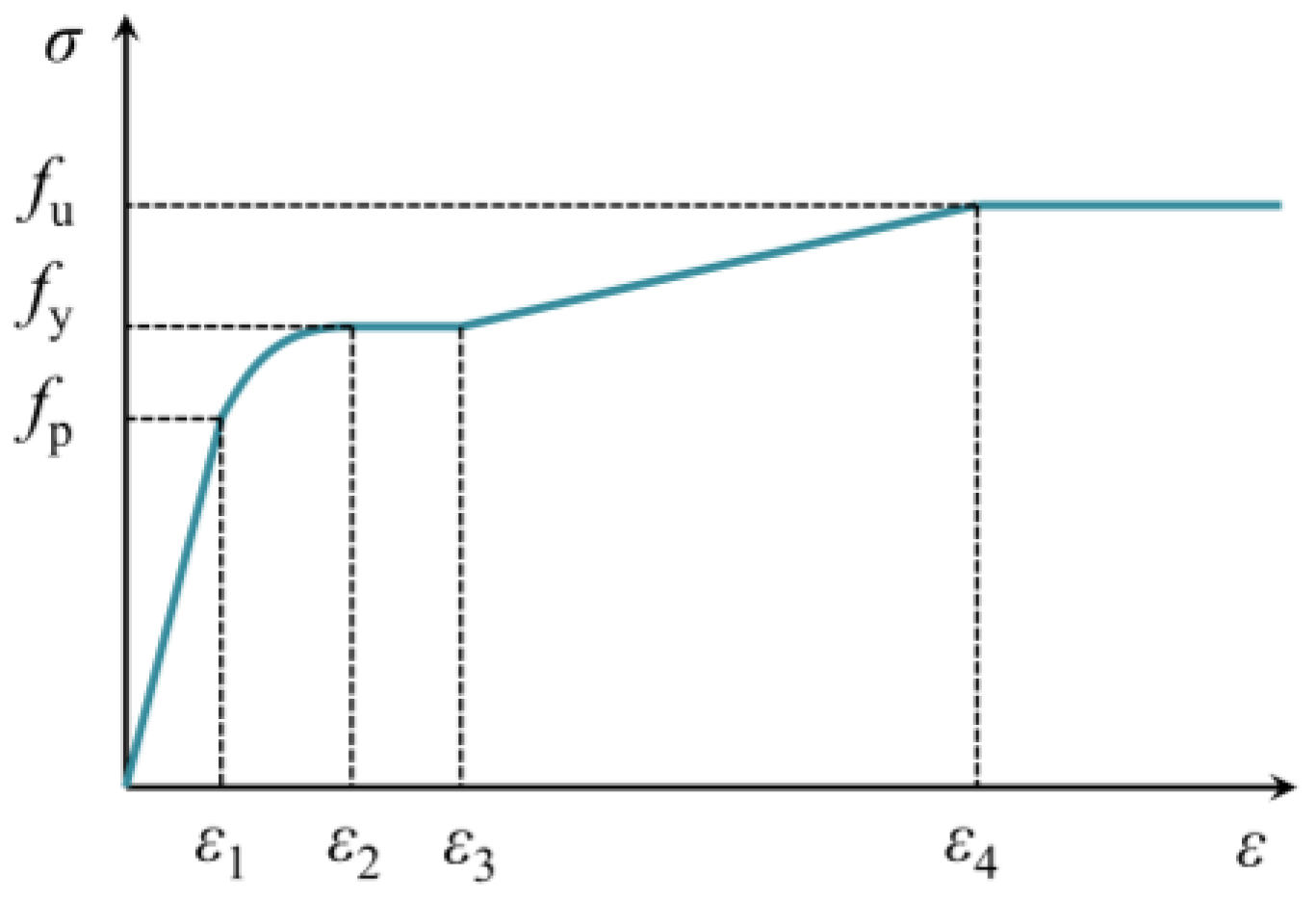
2.1.2. Steel
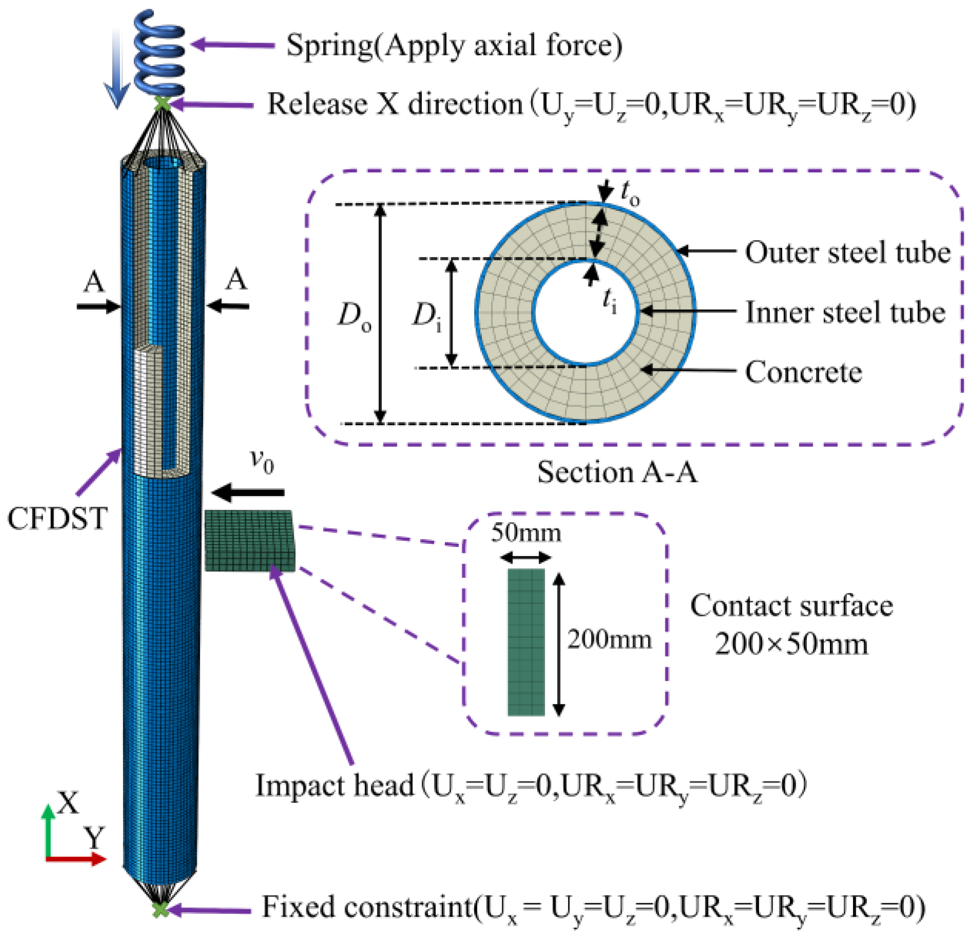
2.2. Element and Constraint
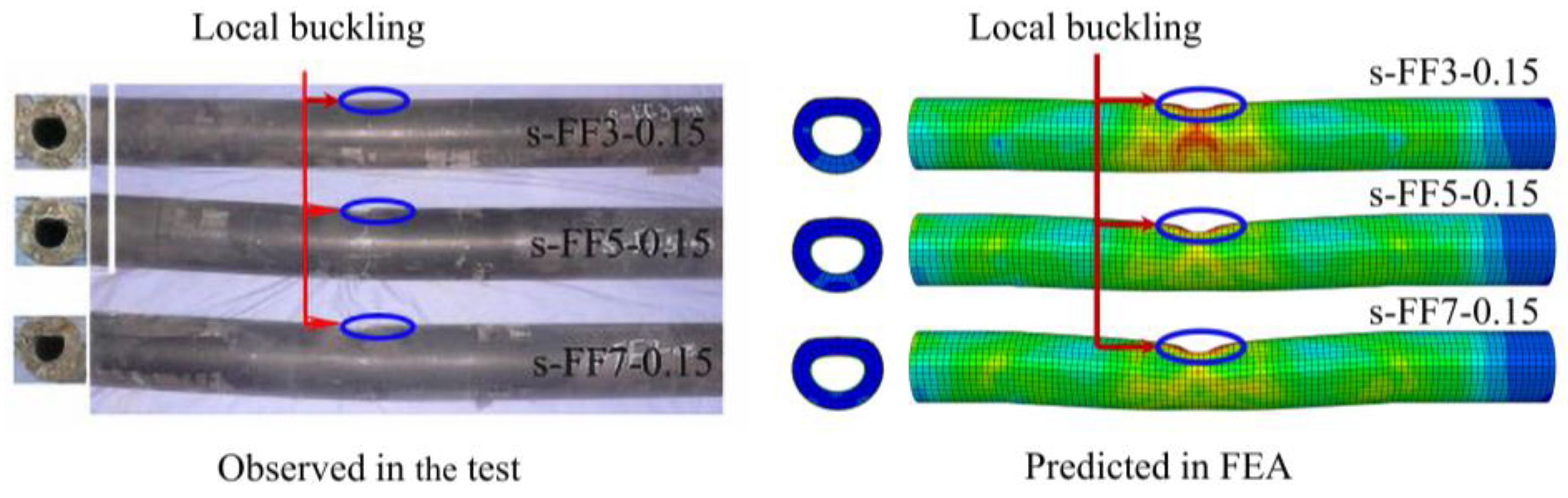
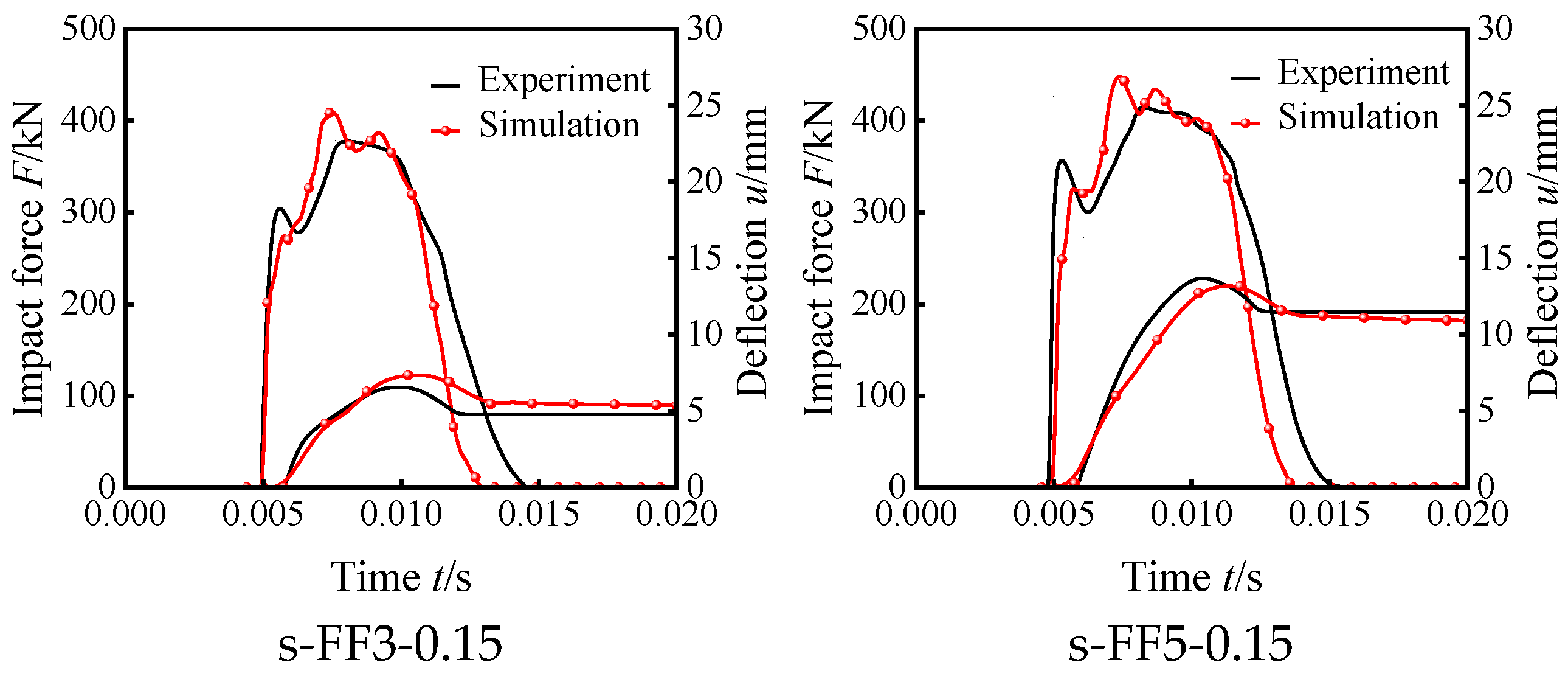
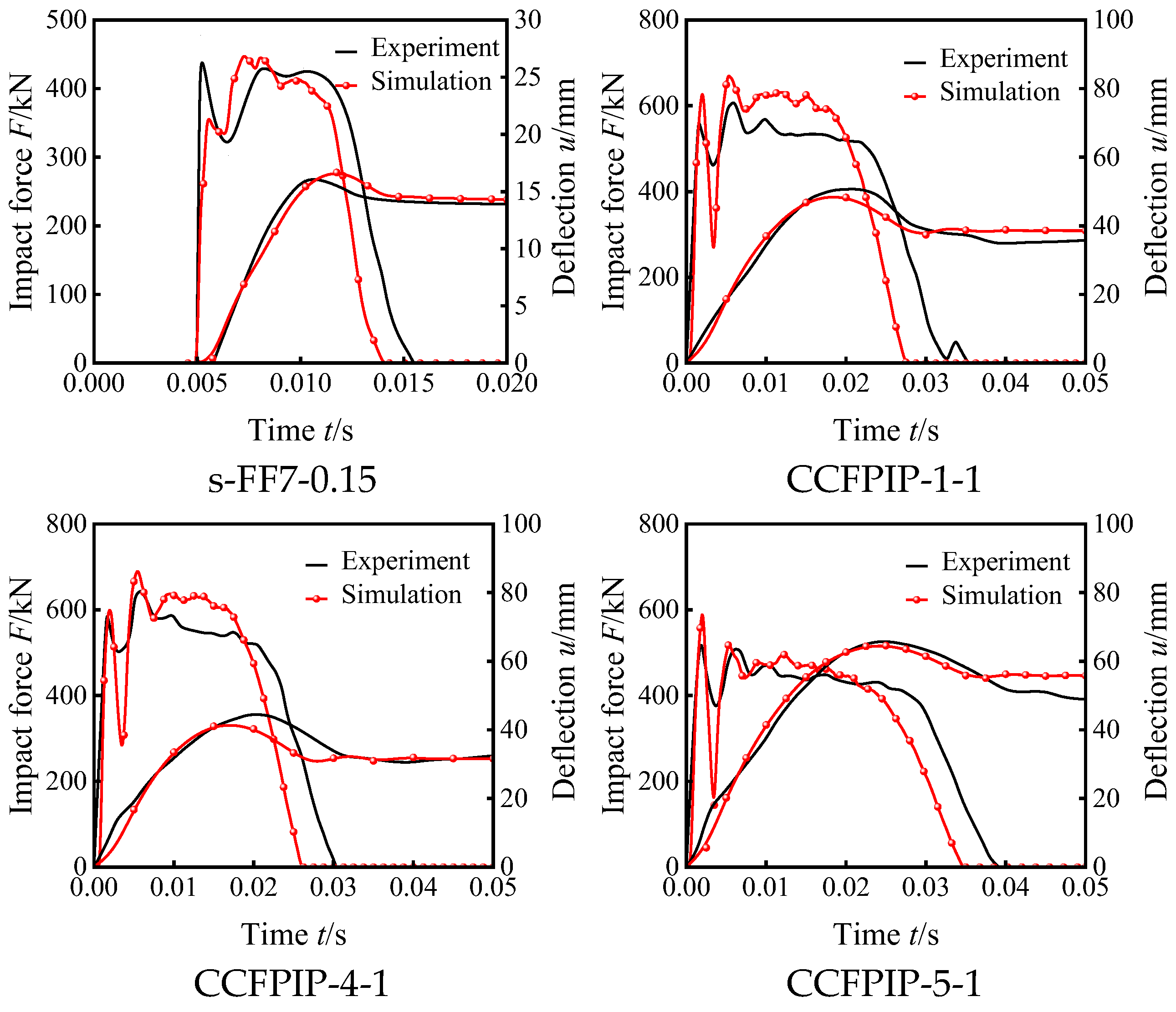
2.3. Verification
3. Parameter Analysis
3.1. Specimen Design
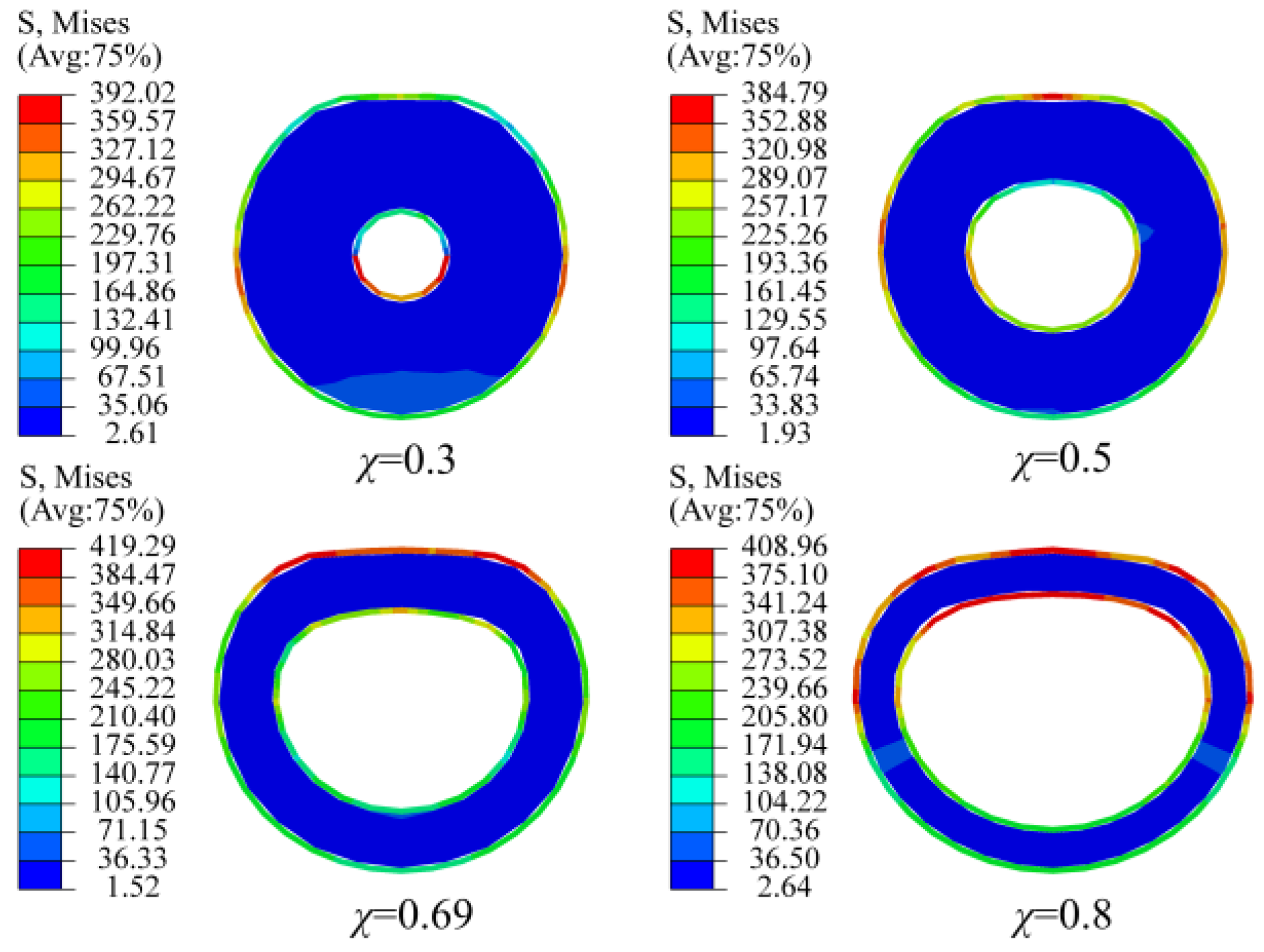
3.2. Influence of Hollow Ratio
3.3. Influence of Axial Compression Ratio
3.4. Influence of Impact Energy
3.5. Influence of Slenderness Ratio
3.6. Influence of Concrete Strength
3.7. Influence of Steel Strength
4. Practical Formulas
5. Conclusions
- (1)
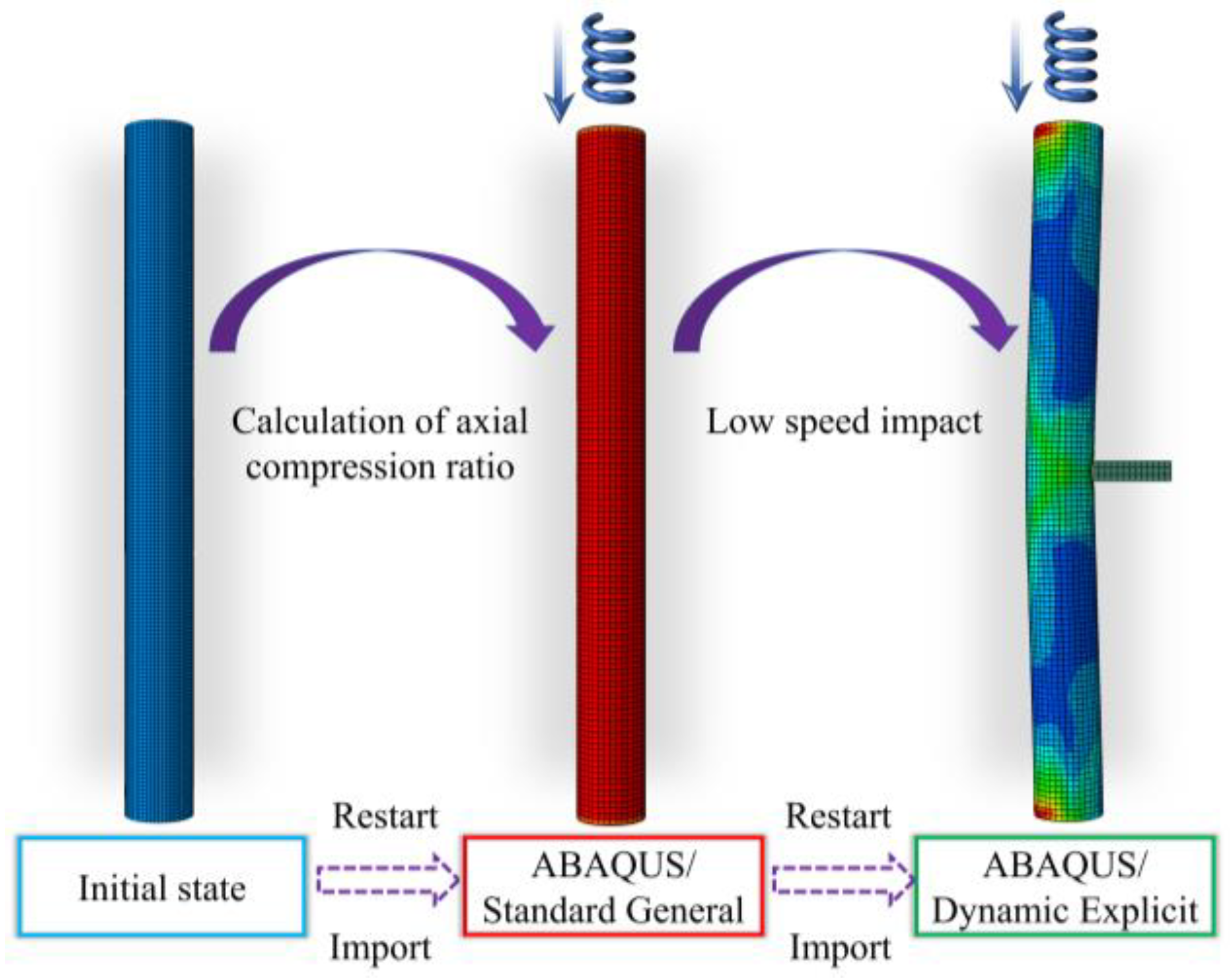
- The numerical model established in this paper can be used to accurately analyze the dynamic responses of the CFDST column under the coupling action of axial force and lateral impact. The axial compression state of the column can be simulated by importing the result of static analysis into this explicit model as an initial stress field.
- (2)
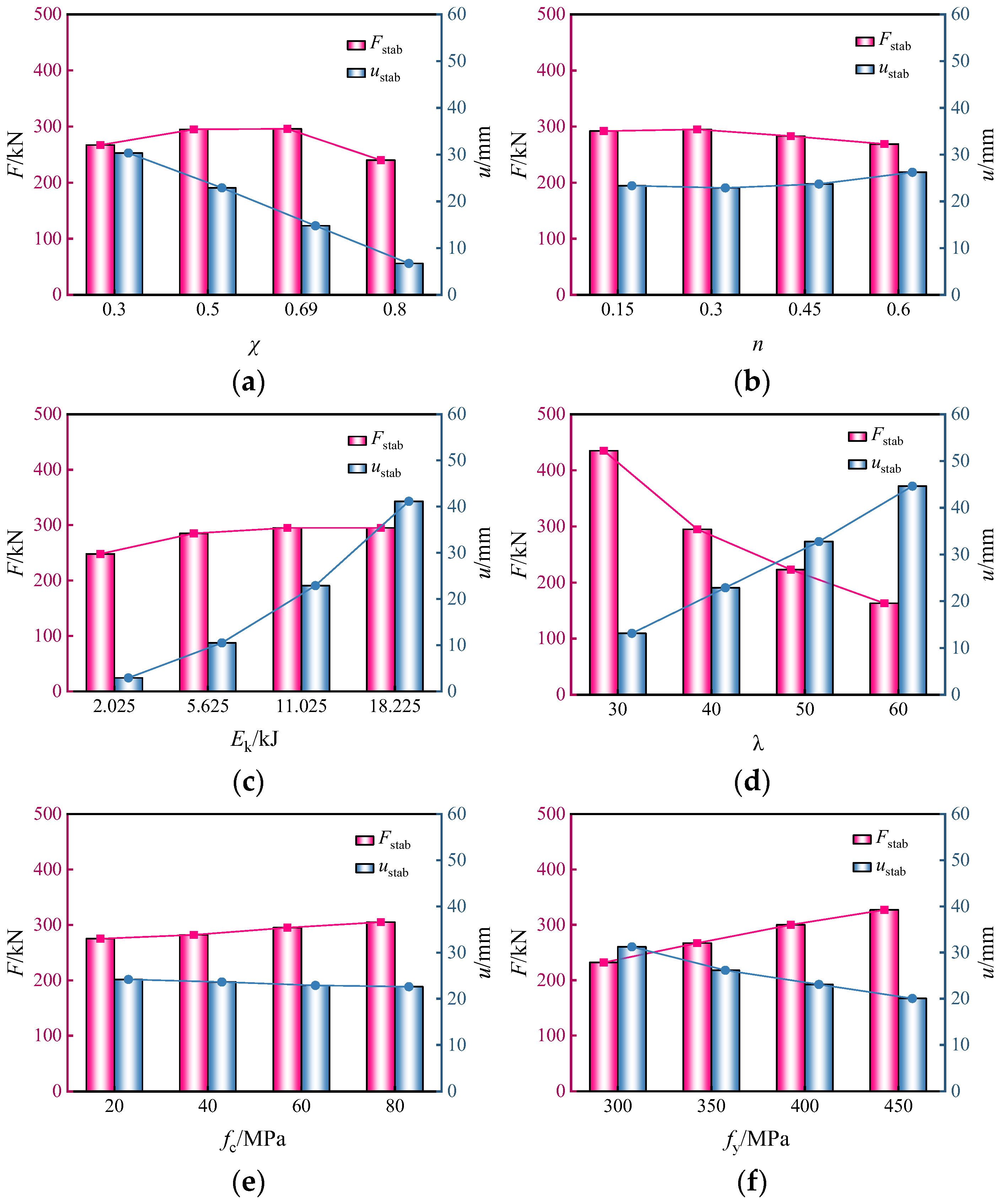
- With the increase in the hollow ratio from 0.3 to 0.8, the residual mid-span deflection of the CFDST column decreases by 77.9%. The main deformation model of the column changes from overall bending to local depression at the impact site. The mid-span deflection shows an increasing trend following a decreasing one with the axial compression ratio increasing. The axial compression accelerates the overall bending deformation of the column under lateral impact when the axial compression state is relatively high. With the increase in the slenderness ratio from 30 to 60, the plateau impact force decreases by 62.5%, and the residual mid-span deflection increases by 240.5%. The increase in the material strength and impact energy can also increase the impact force to varying degrees.
- (3)
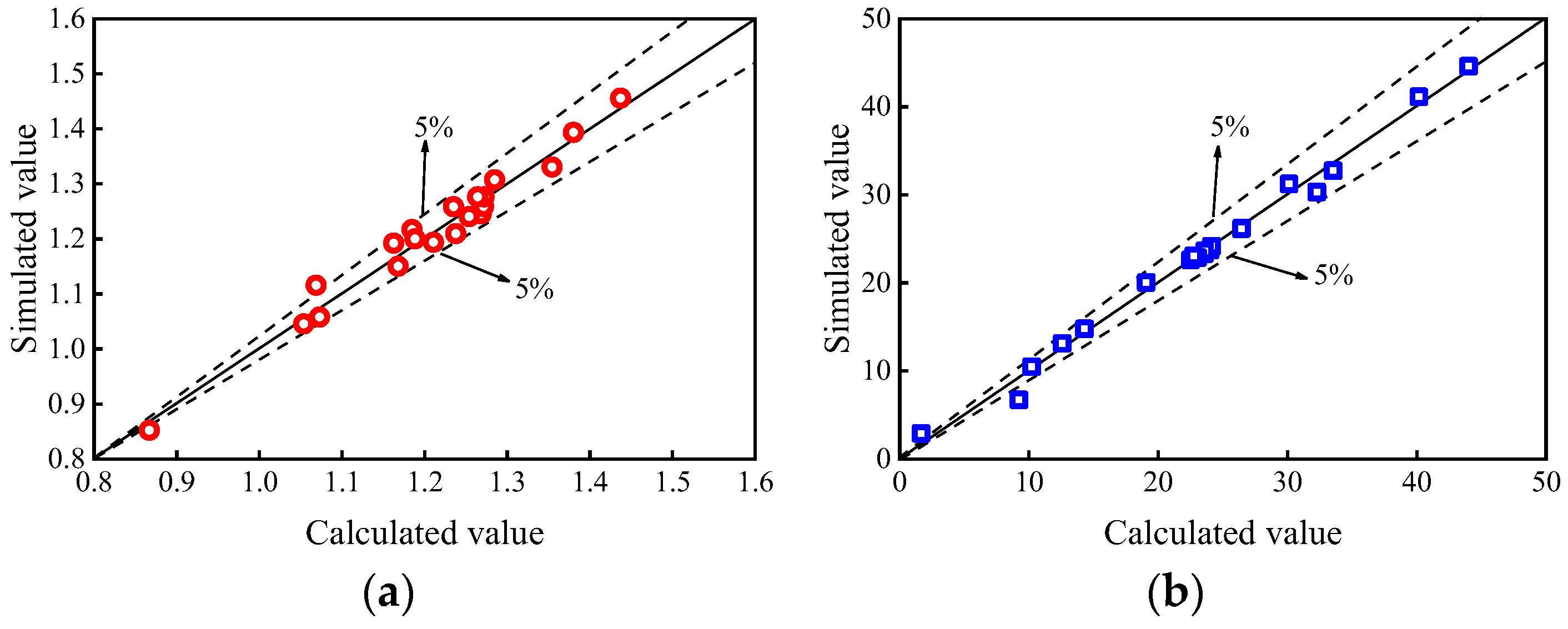
- The practical formulas for impact-bearing capacity and residual mid-span deflection of the CFDST column under lateral impact are accurate enough in the validity limits. The formula for impact-bearing capacity could be used to guide the design of CFDST columns under lateral impact, and the formula for residual mid-span deflection could also be significant for the failure criterion of CFDST columns under lateral impact.
Author Contributions
Funding
Data Availability Statement
Acknowledgments
Conflicts of Interest
References
- Huang, H.; Qi, B.H.; Wang, H.Z. Axial compressive behavior of ultra-high performance concrete short columns with large hollow ratio circular hollow sandwich steel tube. Prog. Steel Build. Struct. 2022, 24, 24–31, 46. [Google Scholar]
- Yu, X.; Tao, Z. Experimental study on residual bearing capacity of hollow sandwich concrete-filled steel tubular short axial compression column after fire. Ind. Archit. 2009, 39, 9–13. [Google Scholar]
- Sulthana, U.M.; Jayachandran, S.A. Axial compression behaviour of long concrete filled double skinned steel tubular columns. Structures 2017, 9, 157–164. [Google Scholar]
- Hou, C.C. Study on Performance of Circular Concrete-Filled Steel Tubular (CFST) Members under Low Velocity Transverse Impact. Master’s Thesis, Tsinghua University, Beijing, China, 2012. [Google Scholar]
- Feng, Z.J.; Wang, X.L.; Zhang, S.F. Experimental investigation on cantilever square CFST columns under lateral continuous impact loads. J. Constr. Steel Res. 2022, 196, 107416. [Google Scholar] [CrossRef]
- Wang, W.D.; Zheng, L.; Xian, W. Performance of the CFST column to composite beam connection under static and impact loads. J. Constr. Steel Res. 2022, 198, 107567. [Google Scholar] [CrossRef]
- Wang, R.; Han, L.H.; Zhao, X.L. Experimental behavior of concrete filled double steel tubular (CFDST) members under low velocity drop weight impact. Thin-Walled Struct. 2015, 97, 279–295. [Google Scholar] [CrossRef]
- Shi, Y.; Li, X.Y.; Zhang, J.B. Experimental study on lateral impact of hollow sandwich metal tube concrete members. J. Vib. Meas. Diagn. 2020, 40, 982–988. [Google Scholar]
- Wang, B.B.; Wang, R. Effect of hollow ratio on crash worthiness of stainless steel concrete steel double-skin tubular columns. Explos. Shock. Waves 2018, 38, 204–211. [Google Scholar]
- An, G.Q.; Zhao, H.; Wang, R. Calculation method for impact resistance of circular concrete-filled double-skin tubular columns with external stainless steel tube. Eng. Mech. 2021, 38, 227–236. [Google Scholar]
- Aghdamy, S.; Thambiratnam, D.P.; Dhanasekar, M. Effects of structure-related parameters on the response of concrete-filled double-skin steel tube columns to lateral impact. Thin-Walled Struct. 2016, 108, 351–368. [Google Scholar] [CrossRef]
- Kang, L.J.; Fan, W.; Liu, B. Numerically efficient analysis of concrete-filled steel tubular columns under lateral impact loading. J. Constr. Steel Res. 2021, 179, 106564. [Google Scholar] [CrossRef]
- Jahami, A.; Temsah, Y.; Khatib, J. The behavior of CFRP strengthened RC beams subjected to blast loading. Mag. Civ. Eng. 2021, 103, 10309. [Google Scholar]
- Wu, H.; Peng, Y.L.; Fang, Q. Experimental and numerical study of ultra-high performance cementitious composites filled steel tube (UHPCC-FST) subjected to close-range explosion. Int. J. Impact Eng. 2020, 141, 103569. [Google Scholar] [CrossRef]
- Han, L.H.; Yao, G.H.; Tao, Z. Performance of concrete filled thin-walled steel tubes under pure torsion. Thin-Walled Struct. 2007, 45, 24–36. [Google Scholar] [CrossRef]
- American Concrete Institute. Building Code Requirement for Structural Concrete and Commentary: ACI Committee 318(ACI 318); American Concrete Institute: Detroit, MI, USA, 2005. [Google Scholar]
- Cai, J.; Yu, Y.; Chen, Q.J. Parameter study on dynamic response of concrete filled square tube under lateral impact. J. Cent. S. Univ. 2019, 50, 409–419. [Google Scholar]
- Zeinoddini, M.; Parke, G. A. R.; Harding, J. E. Axially pre-loaded steel tubes subjected to lateral impacts: An experimental study. Int. J. Impact Eng. 2002, 27, 669–690. [Google Scholar] [CrossRef]
- Wang, R.; Han, L.H.; Zhao, X.L. Analytical behavior of concrete filled double steel tubular (CFDST) members under lateral impact. Thin-Walled Struct. 2016, 101, 129–140. [Google Scholar] [CrossRef]
- Kang, C.M.; Wang, R.; Zhu, X. The influence of axial compression ratio on the lateral impact performance of concrete filled steel tube columns. Eng. Mech. 2020, 37, 254–260. [Google Scholar]
- Wang, Y.; Qian, X.D.; Liew, J.Y.R. Experimental behavior of cement filled pipe-in-pipe composite structures under transverse impact. Int. J. Impact Eng. 2014, 72, 1–16. [Google Scholar] [CrossRef]
- Han, L.H.; Li, Y.J.; Liao, F.Y. Concrete-filled double skin tubular (CFDST) columns subjected to long-term sustained loading. Thin-Walled Struct. 2011, 49, 1534–1543. [Google Scholar] [CrossRef]
- Han, L.H.; Huang, H.; Tao, Z. Concrete-filled double skin steel tubular (CFDST) beam-columns subjected to cyclic bending. Eng. Struct. 2006, 28, 1698–1714. [Google Scholar] [CrossRef]
- Guo, J.L.; Cai, J.; Zuo, Z.L. Simplified Dynamic Analysis of Reinforced Concrete Beams under Impact Actions. Proceedings of the Institution of Civil Engineers. Struct. Build. 2017, 170, 211–224. [Google Scholar] [CrossRef]


| ν | ρ/(kg·m−3) | e | ɑf | Kc | μ/10−3 | φ/(°C) |
|---|---|---|---|---|---|---|
| 0.2 | 2500 | 0.1 | 1.16 | 2/3 | 1 | 30 |
| t/mm | ρ/(kg·m−3) | fy/MPa | fu/MPa | Es/GPa | ν |
|---|---|---|---|---|---|
| 3 | 7850 | 396 | 633.6 | 206 | 0.3 |
| Specimen | L/mm | Do × to | Di × ti | fcu/MPa | fyo/MPa | fyi/MPa | m0/kg | v0/(m/s) | n |
|---|---|---|---|---|---|---|---|---|---|
| s-FF3-0.15 | 1500 | 170 × 2 | 100 × 3 | 60.2 | 396 | 389 | 229.8 | 7.6 | 0.15 |
| s-FF5-0.15 | 1500 | 170 × 2 | 100 × 3 | 60.2 | 396 | 389 | 229.8 | 9.8 | 0.15 |
| s-FF7-0.15 | 1500 | 170 × 2 | 100 × 3 | 60.2 | 396 | 389 | 229.8 | 10.8 | 0.15 |
| CCFPIP-1-1 | 2000 | 219.1 × 10 | 139.7 × 5 | 63.8 | 400 | 420 | 1350 | 7.56 | 0 |
| CCFPIP-5-1 | 2000 | 219.1 × 6.3 | 139.7 × 6.3 | 60.6 | 395 | 395 | 1350 | 7.65 | 0 |
| CCFPIP-7-1 | 2000 | 219.1 × 6.3 | 168.3 × 6.3 | 60.6 | 395 | 395 | 1350 | 7.72 | 0 |
| Specimen | Fmax/kN | Fstab/kN | umax/mm | ustab/mm | ||||||||
|---|---|---|---|---|---|---|---|---|---|---|---|---|
| Numerical | Test | Error/% | Numerical | Test | Error/% | Numerical | Test | Error/% | Numerical | Test | Error/% | |
| s-FF3-0.15 | 409 | 374 | 9 | 376 | 380 | −1 | 6.6 | 7.4 | −10 | 5.4 | 5.4 | 0 |
| s-FF5-0.15 | 449 | 432 | 4 | 419 | 390 | 7 | 13.8 | 13.2 | 5 | 11.5 | 11 | 5 |
| s-FF7-0.15 | 449 | 442 | 2 | 420 | 385 | 9 | 16.1 | 16.7 | −4 | 13.8 | 14.4 | −4 |
| CCFPIP-1-1 | 639 | 606 | 5 | 602 | 545 | 10 | 50.8 | 48.6 | −5 | —— | —— | —— |
| CCFPIP-4-1 | 693 | 644 | 8 | 605 | 572 | 6 | 44.6 | 41.6 | −7 | —— | —— | —— |
| CCFPIP-5-1 | 604 | 546 | 10 | 458 | 451 | 2 | 65.9 | 64.6 | −2 | —— | —— | —— |
| Specimen | Di × ti (mm) | L (mm) | χ | n | v0 (m·s−1) | λ | fc (MPa) | fyo (MPa) | fyi (MPa) | Nu (kN) | Fmax (kN) | Fstab (kN) | umax (mm) | ustab (mm) |
|---|---|---|---|---|---|---|---|---|---|---|---|---|---|---|
| S-3374 | 52 × 3 | 1800 | 0.3 | 0.3 | 7 | 40 | 60 | 396 | 396 | 1964 | 569 | 267 | 34.1 | 30.3 |
| S-5374 | 88 × 3 | 1800 | 0.5 | 0.3 | 7 | 40 | 60 | 396 | 396 | 1894 | 439 | 295 | 26.7 | 22.9 |
| S-7374 | 120 × 3 | 1800 | 0.69 | 0.3 | 7 | 40 | 60 | 396 | 396 | 1743 | 370 | 296 | 18.9 | 14.8 |
| S-8374 | 140 × 3 | 1800 | 0.8 | 0.3 | 7 | 40 | 60 | 396 | 396 | 1604 | 277 | 240 | 8.6 | 6.7 |
| S-5174 | 88 × 3 | 1800 | 0.5 | 0.15 | 7 | 40 | 60 | 396 | 396 | 1894 | 440 | 292 | 27.2 | 23.3 |
| S-5474 | 88 × 3 | 1800 | 0.5 | 0.45 | 7 | 40 | 60 | 396 | 396 | 1894 | 432 | 283 | 28.1 | 23.7 |
| S-5674 | 88 × 3 | 1800 | 0.5 | 0.6 | 7 | 40 | 60 | 396 | 396 | 1894 | 421 | 269 | 29.6 | 26.2 |
| S-5334 | 88 × 3 | 1800 | 0.5 | 0.3 | 3 | 40 | 60 | 396 | 396 | 1894 | 323 | 248 | 6.4 | 2.9 |
| S-5354 | 88 × 3 | 1800 | 0.5 | 0.3 | 5 | 40 | 60 | 396 | 396 | 1894 | 341 | 285 | 14.5 | 10.5 |
| S-5394 | 88 × 3 | 1800 | 0.5 | 0.3 | 9 | 40 | 60 | 396 | 396 | 1894 | 522 | 295 | 44.9 | 41.1 |
| S-5373 | 88 × 3 | 1350 | 0.5 | 0.3 | 7 | 30 | 60 | 396 | 396 | 1894 | 475 | 435 | 15.2 | 13.1 |
| S-5375 | 88 × 3 | 2250 | 0.5 | 0.3 | 7 | 50 | 60 | 396 | 396 | 1894 | 440 | 223 | 38.5 | 32.8 |
| S-5376 | 88 × 3 | 2700 | 0.5 | 0.3 | 7 | 60 | 60 | 396 | 396 | 1894 | 442 | 163 | 52.4 | 44.6 |
| S-5374-C20 | 88 × 3 | 1800 | 0.5 | 0.3 | 7 | 40 | 20 | 396 | 396 | 1312 | 406 | 275 | 28.8 | 24.2 |
| S-5374-C40 | 88 × 3 | 1800 | 0.5 | 0.3 | 7 | 40 | 40 | 396 | 396 | 1601 | 423 | 282 | 27.7 | 23.6 |
| S-5374-C80 | 88 × 3 | 1800 | 0.5 | 0.3 | 7 | 40 | 80 | 396 | 396 | 2180 | 457 | 305 | 26.2 | 22.6 |
| S-5374-300 | 88 × 3 | 1800 | 0.5 | 0.3 | 7 | 40 | 60 | 300 | 300 | 1646 | 402 | 232 | 34.4 | 31.2 |
| S-5374-350 | 88 × 3 | 1800 | 0.5 | 0.3 | 7 | 40 | 60 | 350 | 350 | 1775 | 420 | 267 | 29.7 | 26.2 |
| S-5374-400 | 88 × 3 | 1800 | 0.5 | 0.3 | 7 | 40 | 60 | 400 | 400 | 1901 | 454 | 300 | 26.6 | 23.1 |
| S-5374-450 | 88 × 3 | 1800 | 0.5 | 0.3 | 7 | 40 | 60 | 450 | 450 | 2033 | 452 | 327 | 24.1 | 20.0 |
| Impact Position | χ | n | λ | Ek/kJ | fc/MPa | fy/MPa |
|---|---|---|---|---|---|---|
| Mid-span | 0.3~0.8 | 0.15~0.6 | 30~60 | 2.025~18.225 | 20~80 | 300~450 |
Disclaimer/Publisher’s Note: The statements, opinions and data contained in all publications are solely those of the individual author(s) and contributor(s) and not of MDPI and/or the editor(s). MDPI and/or the editor(s) disclaim responsibility for any injury to people or property resulting from any ideas, methods, instructions or products referred to in the content. |
© 2023 by the authors. Licensee MDPI, Basel, Switzerland. This article is an open access article distributed under the terms and conditions of the Creative Commons Attribution (CC BY) license (https://creativecommons.org/licenses/by/4.0/).
Share and Cite
Guo, J.-L.; Pan, S.; Guo, X.; Wu, Z.-Y. Numerical Simulation of the Dynamic Responses and Impact-Bearing Capacity of CFDST Columns under Lateral Impact. Buildings 2023, 13, 805. https://doi.org/10.3390/buildings13030805
Guo J-L, Pan S, Guo X, Wu Z-Y. Numerical Simulation of the Dynamic Responses and Impact-Bearing Capacity of CFDST Columns under Lateral Impact. Buildings. 2023; 13(3):805. https://doi.org/10.3390/buildings13030805
Chicago/Turabian StyleGuo, Jin-Long, Shuang Pan, Xiao Guo, and Zheng-Yu Wu. 2023. "Numerical Simulation of the Dynamic Responses and Impact-Bearing Capacity of CFDST Columns under Lateral Impact" Buildings 13, no. 3: 805. https://doi.org/10.3390/buildings13030805