1. Introduction
The design of old structures such as old masonry churches and heritage structures are usually not made to resist lateral loads, making them vulnerable to seismic actions [
1]. For the rising occurrence of earthquake events, protecting heritage structures has been a part of continuous research that aims to substantially reduce the damage that these structures can suffer from seismic activities. Parisi and Augenti [
2] made account of the types of damages to cultural heritage buildings caused by earthquake. The majority of the failure modes include the collapse of a portion of the structure, loss of masonry integrity, and in-plane damage to the main façade. A typical failure that was observed for URM walls is in in-plane shear. Retrofitting and strengthening interventions are required to make the masonry wall act as a part of the system to dissipate the lateral forces brought by seismic activities. This will enhance the building resistance and achieve the required seismic safety level in most structural codes [
3].
1.1. In-Plane Shear
The collapse mechanism of heritage structures follows out-of-plane and in-plane mechanisms. Failure mechanisms of walls are influenced mainly by the quality and strength of the connection between the walls and the other structural elements. If better connections are implemented, out-of-plane mechanisms are usually prevented, and the critical element becomes the in-plane mechanism [
3]. Design provisions for out-of-plane shear response are established, while strengthening for in-plane shear is more complex [
4]. In the current study, the strengthening of walls for in-plane diagonal shear is being explored.
1.2. Strengthening Methodologies
There are different methodologies for strengthening reinforced and unreinforced walls. Strengthening URM buildings includes traditional methods such as surface treatments, shotcrete [
5], reinforced high performance mortar [
6], prestressing with steel bars/ties, and grout injections. An alternative technique is by Steel Fiber-Reinforced Mortar (SFRM) coating that is reinforced with short fibers that are shorter than the coating thickness and randomly distributed in the mortar matrix [
1]. Other common methods are the use of externally bonded fiber-reinforced polymers (FRP) and surface coatings reinforced with grid reinforcement. The strengthening includes the used of mesh carbon fabric [
7], glass fiber-reinforced plastic (GFRP) [
8], and polyparaphenylene benzobisoxazole (PBO) fiber grid [
9] covered by epoxy-based adhesive or normal strength mortar. Protecting heritage structures must also include the protection of the environment. This can be achieved through the usage of different innovative approaches of repair and strengthening for old structures. The call for more environmentally friendly construction materials is stimulated by the need for energy-efficient construction with minimal carbon footprint. Nowadays, the use of natural fibers on mortar and concrete is being explored along with the use of geopolymers to lessen the use of conventional cement binder—which contributes largely to the carbon emission. The application of bamboo fibers as reinforcement for developing mill scale (MS)- and fly ash (FA)-based geopolymer composites and as textile reinforcement is being explored as its fibers exhibit attractive mechanical properties and shows competitive results. In the current study, a proposed textile system made of MS and FA geopolymer reinforced with bamboo fiber is used as an innovative repair system for URM walls. The textile system will give the structure strength against lateral loading and improve the walls’ performance in the dissipation of lateral loads.
One of the major challenges in implementing interventions for heritage structures is the idea of protecting their cultural and aesthetic value. Studies of Lourenço et al. [
10] highlighted the importance of following the recommendations made by organizations that protect the cultural heritage of old architectural buildings. Such structures require in-depth analysis and planning to provide structurally sound engineering techniques that can withstand seismic activities without hampering the historic and aesthetic value of the structure. In the recommendation of the International Council on Monuments and Sites (ICOMOS, 2001) [
11], a detailed inspection of the crack pattern may provide the load paths within a structure, thus providing specific areas of target for strengthening intervention. Petrozzi et al. [
12] made use of a strengthening technique that is aesthetically acceptable. In their study, the application of strengthening mesh by Blondet et al. [
13] is adapted, placing the mesh externally against the walls in the form of straps along the corners of the wall to control the formation of cracks. The recommendations also follow the standard framework for seismic evaluation of existing buildings governed by the Federal Emergency Management Agency (FEMA) and the American Society of Civil Engineers (ASCE). The process includes the selection process of performance objectives to be used, the level of seismicity through spectral response acceleration and Peak Ground Acceleration (PGA), as-built information, structural design, and retrofitting. The strengthening method using externally bonded mesh is adapted for the current study using the proposed bamboo fiber-reinforced textile geopolymer system.
1.3. Determination of In-Plane Shear through Experimental Tests
There are several studies that cited ASTM E519 or the standard test method for diagonal tension (shear) in masonry assemblages for investigating in-plane shear performance of walls [
14]. Sagar et al. [
15] investigated the shear performance of 350 mm × 350 mm × 78 mm-thick small wallette specimens strengthened with a fabric-reinforced cementitious matrix. It is observed that strengthening one side of the wall yields an eccentric distribution of force and strengthening both sides is ideal. In a study by Oskouei et al. [
16], in-plane behavior of various retrofitted URM walls was also investigated. A control specimen that was unreinforced and wallette specimens reinforced with mortar coating, mesh reinforcement, and polypropylene (PP) bands were subjected to shear tests. The dominant failure mode was found to be in the form of diagonal shear cracks, while the wallettes retrofitted with mortar-coated GFRP mesh were found to be performing better than other specimens.
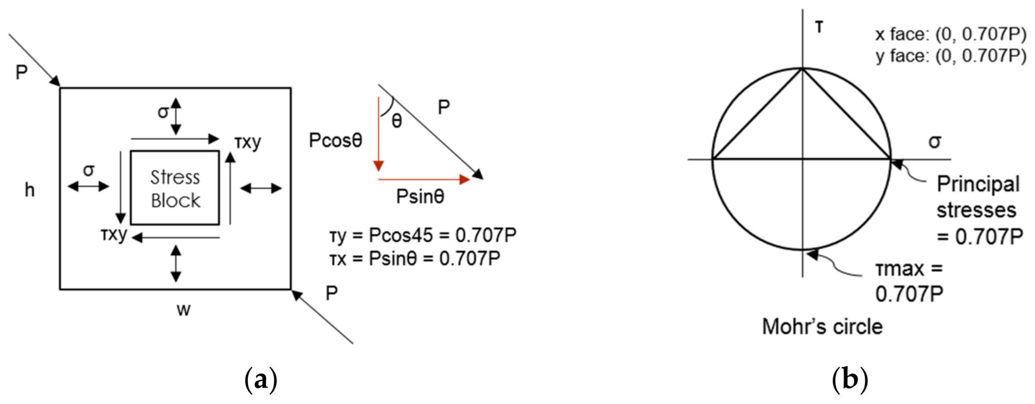
The response of walls is defined with its stress and strain under a certain load [
17]. Generally, shear stress can be obtained by the general formula (Equation (1)) below, and deriving the forces as shown in
Figure 1 will lead to the specific formula of computing in-plane shear stress (Equation (2)).
where,
Ss = shear stress, MPa
F = Applied force, KN
An = Net area net cross-horizontal section of the panel.
where,
t = thickness of wall
L and H = dimensions of the wall
P = diagonal force measured experimentally
while the shear strain can be obtained by
where,
∆V = diagonal shortening along the axis of applied force
∆H = diagonal elongation measured perpendicular to the axis of applied force
g = gauge length.
In the current study, URM wallette specimens reinforced with bamboo fiber textile coated with short bamboo fiber-reinforced geopolymer mortar were subjected to diagonal shear testing to evaluate the increase in shear capacity after strengthening. The comparisons between strengthening one side only and strengthening both sides, with and without bamboo fiber textile, are presented. The resulting shear modulus of each type is used in existing analytical models to verify the experimental results. The experimental/analytical ratios are also presented.
2. Materials and Methods
In the current study, in-plane shear tests for small wall specimens were conducted. The shear performance of small wall specimens, 350 × 350 mm, made of clay bricks, were investigated through the procedures described by ASTM E519 [
14]. The clay bricks manufactured from Rizal, Philippines were tested under compression, as described with the standards for testing brick and structural clay tile or ASTM C67 [
18]. The in-fill mortars were tested under compression, as described by the procedures of construction evaluation of mortars for plain and reinforced unit masonry or ASTM C780 [
19], with a 1:6 cement–sand ratio and a 0.4 mass water–cement ratio, and the strength is in comparison with type O mortar (2.4 MPa), as described by the standard specification for mortars or ASTM C270 [
20].
2.1. Materials
This study used the mill scale (MS) powder and the low calcium Class F fly ash (FA) precursors discussed by Libre et al. [
21]. The MS-FA proportions on the geopolymer paste activated using sodium hydroxide (NaOH) flakes with 98% purity obtained from Taiwan and sodium silicate in the form of waterglass (WG) were used to develop fiber-reinforced geopolymer mortar as a mortar coating for unreinforced walls. Bamboo fibers extracted from Kawayan Tinik using 5% NaOH solution and treated with 10% aluminum sulfate solution are used as the short fibers and fiber textile reinforcement.
2.2. Parameters
Following the study of Libre et al. [
21], the parameters used include the NaOH-to-WG ratio (1:2.5 by weight), whereas the water–solid ratio was kept constant at 0.3 by weight and the activator-to-precursor ratio at 0.38 by weight. The MS-to-FA replacement ratio used in this study is 1:5 or 20%. Sand is used as fine aggregates (1:1 precursor-aggregate ratio) and 20 mm length short bamboo fibers (1.4% fiber loading by weight) are used as reinforcement for the mortar coating in the fiber textile strengthening method.
The specimen variations and method of strengthening for each wallette sample are discussed in detail on the following sections.
2.3. Experimental Procedure
2.3.1. Preparation of Substrate
The substrate is the unreinforced masonry (URM) assembly made of clay bricks and cement-based in-fill mortars. The material specifications of the clay bricks and the in-fill mortars used are shown in
Table 1. The clay bricks, 50 mm × 170 mm × 25 mm thick, are laid staggered inside 350 mm × 350 mm × 50 mm formworks made from phenolic boards to form the running bond layer of the masonry wallette. Sand with 3.5% moisture content is mixed with ordinary Portland cement (OPC), 1:6 cement-sand ratio by weight. For this mix, 0.4 water-cement ratio is used to obtain the workability of the in-fill mortar used in construction. The in-fill mortar is poured into the formworks with the laid bricks to form the URM substrate. Following these instructions, a total of 25 URM wallette substrates were prepared.
2.3.2. Preparation of Bamboo Fiber Textile
The bamboo fibers were prepared using the procedures discussed by Libre et al. [
22]. Bamboo poles of
Bambusa blumeana, or Kawayan Tinik, were cleaned with running water to remove excess dirt and starch. The poles were chopped into smaller slats to maximize the surface area that would be in contact with the sodium hydroxide (NaOH) solution that would be used to delignify the bamboo. Removing lignin that holds the fibers together makes it easier to disturb the bamboo and extract the fibers. The bamboo slats were submerged in 5% NaOH solution. After 24 h, a mechanical softening using rollers was used to extract the bamboo fibers. The extracted bamboo fibers were rinsed with water and treated with additional surface enhancing treatment, 10% aluminum sulfate (Al
2(SO
4)
3) solution for 36 h, to enhance the bonding between the fibers and the geopolymer matrix. Treated bamboo fibers were rinsed with water and air dried for at least 24 h. Portion of the treated bamboo fibers were cut into 20 mm lengths to produce the short bamboo fibers that will be the reinforcement for the geopolymer mortar coating. The remaining portion were prepared for textile-making. A total of 15 pieces of bamboo fiber textile grid were produced with 350 mm × 350 mm and 20 mm spacing of 2-ply 2–3 mm nominal diameter bamboo fiber cordages on both directions. The tensile capacity and tenacity, which is the measure of strength for natural fibers and is equal to the peak load that the fibers can resist in centiNewton (cN) over the fibers’ fineness in Tex or in denier, were reported, as shown in
Table 2.
2.3.3. Preparation of Geopolymer Mortar for Coating
The geopolymer mortar that will be used as coating follows the mix proportion of the geopolymer paste discussed by Libre et al. [
21] with the addition of sand and the short bamboo fibers as reinforcement. The average compressive strength of this geopolymer mortar mix is 3.08 MPa (CoV = 5%) with a split tensile strength of 0.74 MPa (CoV = 5.4%). To start, the mass precursors of 1:5 MS-to-FA ratio was prepared and estimated in order to fill 5 of the prepared wallette substrates for each run. This was to provide five samples of each with a uniform in-fill mix. This as repeated 5 times to fill all of the 25 prepared URM wallette substrates. In this study, 3200 g of FA, 800 g of MS, and 4000 g of sand was combined with a 1.4% bamboo fiber loading of 20 mm fiber length. Intervals of mixing for the addition of short fibers was carried out to minimize the clumping of fibers. The mass of NaOH and waterglass (1:2.5 NaOH-to-WG ratio) for the activator solution was determined using a 0.38 activator-to-precursor ratio. The water-solid ratio of 0.3 by mass was used to determine the amount of water to be used. Dissolved and cooled down NaOH flakes were mixed with waterglass and stirred for 5 min before setting aside. The solution was poured and mixed with the dry mix for 8 min using an automatic mortar mixer. The resulting bamboo fiber-reinforced geopolymer mortar mix was used as the coating for the strengthening method of the URM wallettes.
2.3.4. Strengthening Procedures and Specimen Nomenclature
The 25 URM wallete substrates were divided to 5 groups depending on the strengthening method to be used. Five wallettes remained unreinforced and used as control (C) samples. Five wallettes were plastered on one side with 20-mm-thick geopolymer mortar without bamboo fiber textile (S1). Five wallettes were plastered on both sides with 20-mm-thick geopolymer mortar without bamboo fiber textile (S2). Five wallettes were plastered on one side only with 10-mm-thick mortar before applying the bamboo fiber textile and coating it again with 10-mm-thick geopolymer mortar (BF1). The last five wallettes were plastered on both sides with 10-mm-thick mortar before applying the bamboo fiber textile and coating it again with 10-mm-thick geopolymer mortar to finish (BF2). Cling wrap was used as the curing technique following the curing technique used by Libre et al. [
3]. The wrapped wallettes were left in an undisturbed area for ambient curing with temperature ranges from 34–38 °C, and relative humidity of 40 ± 5%, for 28 days before testing.
2.4. Diagonal Shear Test
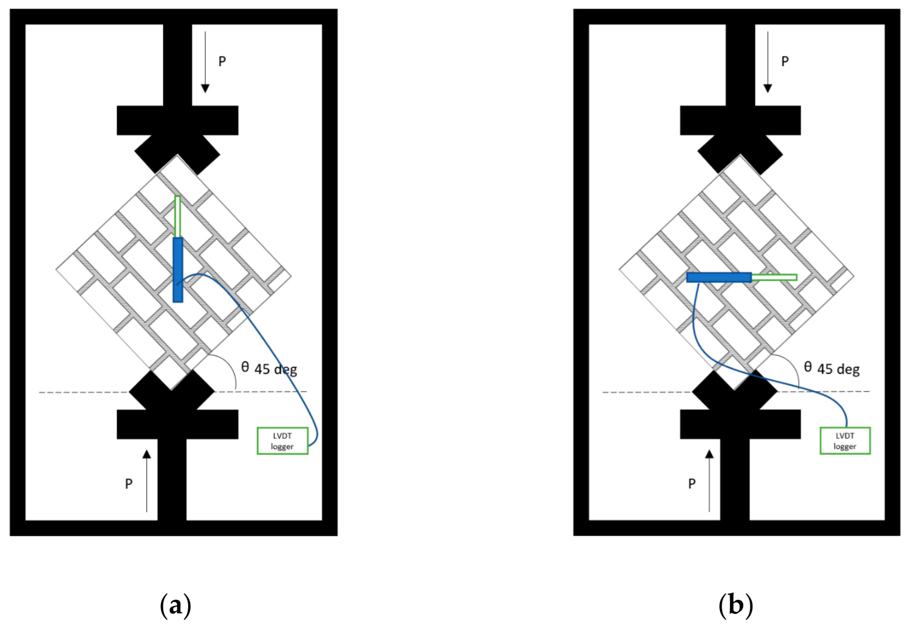
After 28 days of curing, the wallettes were subjected to diagonal shear tests with orientation as shown in
Figure 2. The test was administered using Shimadzu Universal Testing Machine (UTM) model AG-100kNXplus, displacement controlled at 5 mm/min rate. The load force and displacement parallel and perpendicular to the load were recorded using load cell (5 tons capacity) and Linear Variable Differential Transformer (LVDT) transducers, respectively. Both were connected to Almemo 710 Data Logger by Ahlborn.
4. Comparison between Analytical and Experimental Results
In terms of applying the data from the discussed experiments for retrofitting masonry walls, there are some additional tests to consider. The American Concrete Institute (ACI) introduced ACI 549.4R, a guide to the design and construction of externally bonded fabric-reinforced cementitious matrix for masonry structures [
25]. As it is more established, some authors [
7,
15,
24] made use of the existing analytical models from ACI 549.4R to estimate the in-plane shear strength of strengthened masonry walls. The general idea is governed by the equation,
where
Vn is the nominal shear capacity,
Vm is the contribution of the masonry wall, and
Vft and
Vfm are the shear capacities of the strengthening method with and without textile, respectively.
The shear contribution of the masonry,
Vm, is calculated using the equation,
where
fvd is the average shear stress based on control samples C,
d is length of one side of the wallette, and
t is the thickness of the wallette.
The shear contribution of the strengthening method with short bamboo fiber-reinforced geopolymer mortar but without the geotextile,
Vfm, is calculated by the equation,
where
s is the number of sides strengthened,
fvs is the average shear stresses of wallettes (S1 and S2),
d is the length of one side, and
t is the thickness of the wallette.
The shear contribution of the strengthening method with geotextile coated with the short bamboo fiber-reinforced geopolymer mortar,
Vft, is defined and calculated using ACI 549.4R approach and is governed by the equation,
where s is the number of sides strengthened,
n is the number of strengthening mortar layer,
Af is the area of the externally bonded strengthening mortar,
L is the length of the wall,
Ef is the modulus of elasticity of cracked strengthened mortar, and
εfv is the value of ultimate tensile strain of the strengthened mortar—but not more than 0.004.
εfv is the strain considered from a separate tensile test on coupons for the reinforced mortars with textiles [
15]. However, if we are to consider the ultimate tensile strain that can be resisted by the textile used in the current study as shown in
Table 2, which is 0.127 mm/mm, we can consider
εfv as 0.004.
The nominal shear
Vn is analytically computed and compared with the shear in experimental results,
Vexp, discussed in previous sections. The summary of the contributions and the experimental/analytical ratio (
Vexp/
Vn) is shown in
Table 5.
The accuracy of the model in predicting the added shear capacity using the strengthening method is denoted by the nearness of
Vexp/
Vn to 1. Comparing with the
Vexp/
Vn ratio of 1.48 by Sagar et al. [
15], who used the same ACI 549.4R approach, the results of the models in the current study are more accurate in calculating the nominal shear capacity and contributions of each strengthened URM. As there are no standards to follow when using bamboo fiber geotextile and short bamboo fiber-reinforced geopolymer mortar, the equations presented deemed usable for design purposes.
5. Conclusions and Recommendations
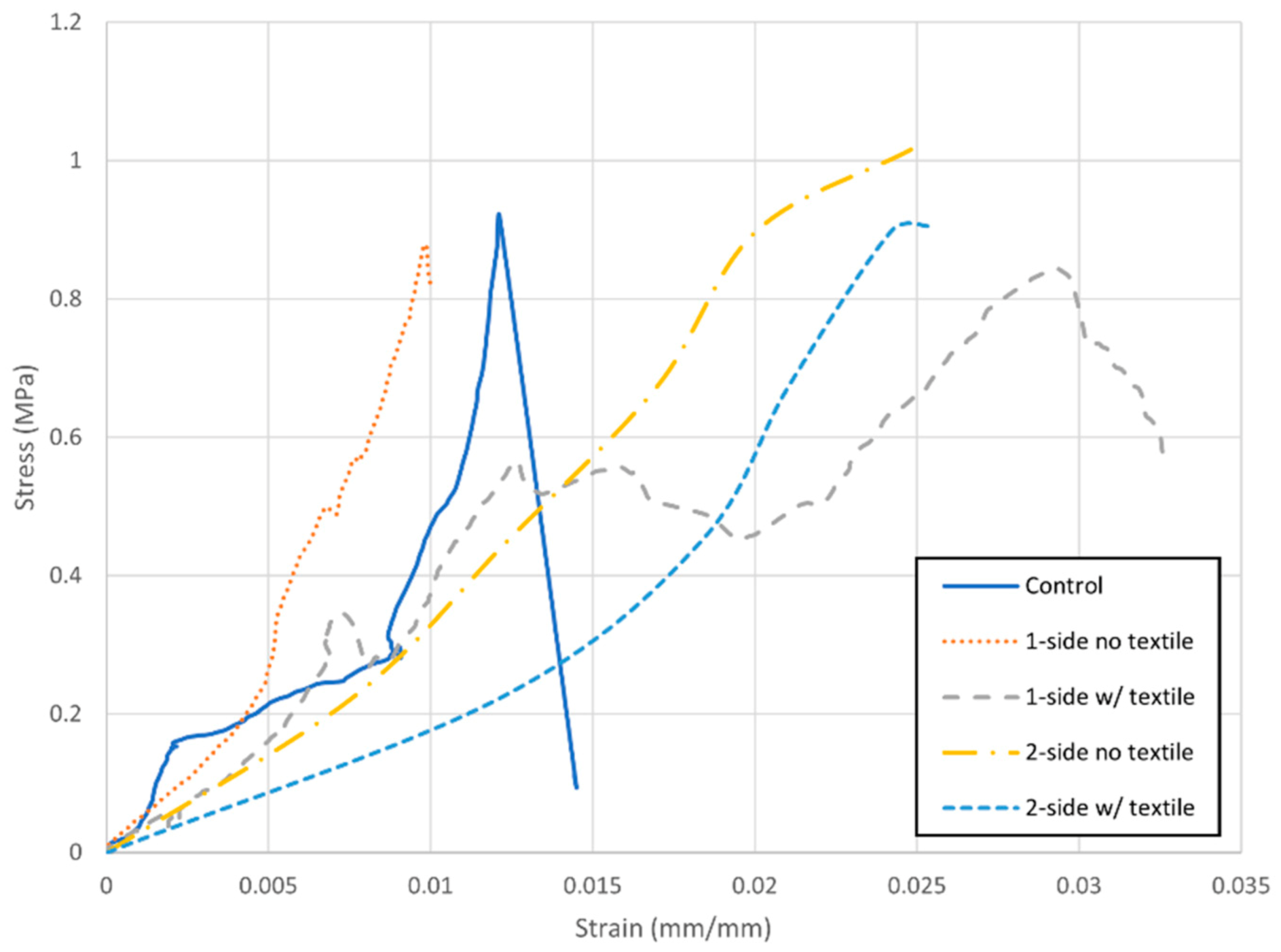
In this study, the performance of a bamboo fiber textile-reinforced geopolymer mortar system in strengthening the in-plane shear strength of URM wall assemblages is investigated through diagonal shear tests. Fibers extracted from Kawayan Tinik and treated with 10% aluminum sulfate were used to produce cordages and textiles to reinforce URM wallette specimens, 350 mm × 350 mm, made of clay bricks and in-fill mortar. Mill scale and fly ash based geopolymer reinforced with short bamboo fibers were used as mortar coating for the textile reinforcement.
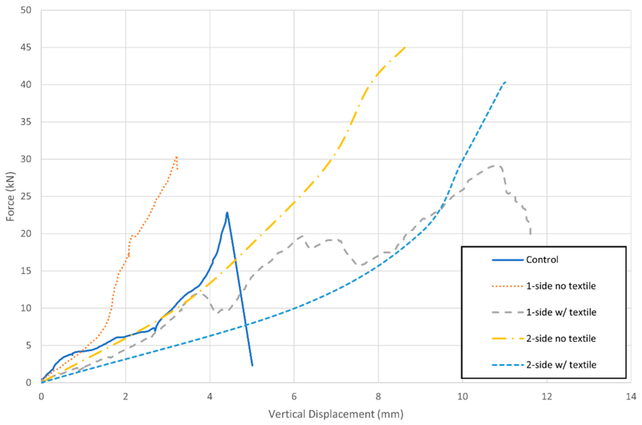
It was observed that strengthening both sides with bamboo textile coated with bamboo fiber-reinforced MS-FA geopolymer mortar increased the average shear force that the walls could resist by 35.80% or 9.58 kN more than the 17.16 kN of URM control samples. An improvement of vertical displacement of 74.78% was also observed for BF2 compared to the control samples C.
There was an increase in deformability of the walls that was expressed by the pseudo-ductility value for S2 and BF2 specimens. From 1.04 of control samples, the pseudo-ductility of BF2 increased up to 1.55, which suggests that the samples still experienced further deformation even after the initial cracking. This signifies that the strengthening method used enhanced the ductility and is important when considering strengthening or retrofitting masonry assemblages.
To maximize the impact of the proposed strengthening method, it is recommended for future studies to conduct cost-benefit analysis, comparing different existing strengthening methods. It is also recommended that the bond between the proposed geopolymer mortar and the substrate be included as part of the optimization in material development.
The results presented on this paper can be used as basis of modulus of rigidity, Gs, and maximum tensile strength of bamboo fiber textiles for strengthening masonry walls, given that the bamboo fibers and the geopolymer mortar to be used are the same.


 ,
, 


