Article

Modelling of CFRP-Strengthened RC Shear Walls with a Focus on End-Anchor Effects

1
Department of Civil and Environmental Engineering, Carleton University, Ottawa, ON K1S 5B6, Canada
2
Structural Engineer in Training, Gray & Fick Ltd., London, ON N6E 2S8, Canada
*
Author to whom correspondence should be addressed.
Buildings 2023, 13(3), 747; https://doi.org/10.3390/buildings13030747
Submission received: 7 February 2023 / Revised: 5 March 2023 / Accepted: 11 March 2023 / Published: 13 March 2023
(This article belongs to the Special Issue Seismic and Durability Evaluation of Concrete Structures)

Abstract

:
This study first provides an overview of the development of a novel tube anchor system for the seismic strengthening or repair of reinforced concrete (RC) shear walls with carbon fibre-reinforced polymer (CFRP) sheets. The new anchor system can significantly improve the load transfer mechanism between the CFRP and supporting RC structural elements, resulting in ductile behaviour of the strengthened shear walls with increases of lateral load capacity and ductility by up to 2.6 and 8.3 times, respectively. The study then presents a new finite element modelling technique capable of capturing the complete cyclic response, i.e., from the elastic behaviour to the ultimate collapse of CFRP-strengthened RC shear walls with the newly developed tube anchor system. Two different modelling approaches are proposed to consider the effects of the tube anchor system. Additionally, other important CFRP- and RC-related mechanisms, including CFRP debonding effects, confinement enhancement, tension stiffening, compression softening, and strength and stiffness degradation under cyclic loads, are also considered in the model. By comparing the analytical and experimental results, it is demonstrated that the proposed modelling approach can accurately replicate the complex behaviour of CFRP-strengthened shear walls with a wide range of aspect ratios, from the ductile flexural behaviour of slender walls to the brittle shear failure of squat walls, without requiring detailed modelling of the anchor system.

1. Introduction

Reinforced concrete (RC) shear walls are commonly used as a lateral load resisting system in structures. Despite significant improvements in the design and construction practice of shear walls in recent decades, many older buildings with shear walls are still found to be vulnerable and prone to severe damage during earthquakes due to insufficient in-plane stiffness, flexural and shear strengths, and/or ductility. The use of fibre reinforced polymer (FRP) sheets is an attractive method for the repair or strengthening of RC structural components. The advantages of FRP composites compared to other repair techniques, such as steel jacketing and concrete caging, include high strength-to-weight ratio, good corrosion resistance, and versatile design. There are different types of fibre materials that can be used for FRP sheets, including glass FRP (GFRP), carbon FRP (CFRP), and basalt FRP (BFRP). Among these, CFRP has gained considerable attention for the repair and strengthening of RC structures. Despite its high cost, CFRP offers higher tensile strength and elastic modulus compared to other fibre materials. It is also lightweight, has excellent corrosion and fatigue resistance, and can be conveniently installed [1,2,3,4].
In recent years, many experimental and analytical studies have been conducted to examine the effectiveness of CFRP strengthening techniques for various RC structural elements, including beams [5,6,7,8], slabs [9,10], columns [11,12], joints [13,14], and shear walls [15,16,17,18,19,20,21,22]. These studies investigated the performance of CFRP-strengthened RC members under different loading conditions, such as monotonic loads [8,10], quasi-static cyclic loads [12,13,14,15], fire [11], and blast and impact [5,8]. While existing studies have provided insights into the behaviour of CFRP-strengthened RC members, there are still important knowledge gaps in this area that need further investigation. In particular, most of the experimental work conducted on CFRP-strengthened shear walls has focused on shear strengthening techniques [11,12,13,14], while the number of experimental studies on flexural-critical shear walls strengthened with CFRP is comparatively less [15,16]. To alleviate this relative lack of test data and to gain a better understanding of the observed behaviour, the development of reliable numerical models that can accurately predict the non-linear response of shear walls reinforced or repaired with CFRP sheets is critical. Although several researchers have developed numerical models for other types of RC structural elements strengthened with FRP [7,12,13], little information exists on the analytical modelling of CFRP-strengthened RC shear walls. Recently, Woods et al. [21] tested CFRP reinforced shear walls using a hybrid simulation method, which involves combining computer models with physical test specimens. Cruz-Noguez et al. [22] and Hassan et al. [23] developed numerical models to compute the nonlinear response of deficient shear walls reinforced with CFRP sheets according to the Intermediate Crack Debonding model proposed by Lu et al. [24]. Vecchio and Bucci [25] presented a finite element (FE) model for the analysis of repaired concrete structures that requires activating and deactivating elements during the analysis to account for the effect of strengthening in the model. Cortes-Puentes and Palermo [26] proposed modelling procedures to reproduce the response of RC shear walls strengthened with steel plates and FRP sheets. The modelling strategy included the development of constitutive bond–slip models for link elements to simulate the anchorage of FRP sheets to concrete foundations.
The anchorage system plays an important role in the behaviour of FRP-strengthened RC structures. The lack of a reliable anchorage system can result in premature debonding failures, preventing FRP sheets from achieving their full tensile capacity. Several types of anchor systems have been developed in the research literature, with the most common ones being the u-jacked anchor system [27], steel clamps [28], mechanically fastened anchors [20], and FRP anchors [29]. Each anchor system has its own advantages and drawbacks. For example, steel clamps and mechanically fastened anchors can be quite effective but are labour intensive and costly. The u-jacked anchor system is less expensive and more convenient for installation, but it may not be as effective as the other anchor systems. The FRP anchor system, which consists of a bundle of fibres in a shape of splayed fan and an anchor dowel, has been shown to be effective in terms of allowing FRP sheets to reach their ultimate strength. However, special care must be taken in the design of these anchors, since they are prone to pull-out failure [29].
In the modelling of CFRP strengthened walls, generally, the effects of the anchor system are neglected because of its high rigidity and stiffness relative to the rest of the wall. While this simplification may be acceptable for walls with conventional anchor systems that are more costly and heavier than required, for walls with new, more efficient anchor systems (e.g., the tube anchor system, described later), the deformation and flexibility resulting from anchoring CFRP at the base need to be considered. Compared to conventional L-shaped steel angle anchors, new anchor systems allow CFRP sheets to achieve their full tensile capacity without any premature failure at the base, significantly improving the strength and ductility of the strengthened wall. At such high stress levels, even small deformations in the anchor system can release a considerable amount of energy from the system and therefore affect the structural response of the wall. One approach to consider these effects is to include every detail of the anchor system in detailed micro FE models. However, the micro-modelling approach is computationally expensive and not practical for design applications. Thus, there is a need for an alternative modelling approach that is not only capable of accurately accounting for the behaviour of the anchor system but is also computationally efficient and practical to use, requiring only a reasonable number of elements and mesh sizes for the analysis.
This paper presents new FE modelling methods for CFRP-strengthened RC shear walls which are capable of considering the effects of the anchor system on the response of shear walls without requiring detailed micro-modelling of the anchor system. The proposed modelling methods will help engineers to better understand the response of CFRP-strengthened shear walls and develop more effective designs for anchor systems. The paper first provides a summary of a series of experimental tests conducted on CFRP repaired/strengthened RC shear walls which led to the development of a novel tube anchor system. Based on the results of these experimental tests, the new FE modelling methods are developed and verified. By comparing the analytical and experimental results, the study demonstrates that accounting for the influence of the anchor system is critical for accurate simulations of the seismic performance of CFRP-strengthened shear walls.

2. Development of Tube Anchor System

Over the last two decades, a comprehensive three-phase experimental program was conducted at Carleton University to investigate the influence of CFRP end-anchorage on the load resistance capacity and seismic behaviour of strengthened/repaired shear walls. In addition to the anchor type, the influence of other key parameters, including the aspect ratio, repair and strengthening scheme, the presence of initial damage, and failure mode, were also explored in the experimental program. The shear walls were subjected to quasi-static reversed cyclic loads in the lateral direction to represent earthquake loading effects. Different from other studies, the wall specimens were reinforced with CFRP sheets rather than CFRP wraps as a more convenient and representative repair or strengthening technique employed in the field, where easy access for the wrapping of FRP sheets around shear walls is difficult or impossible. The results of the experimental program were used to validate the analytical models developed in this paper. Below, a brief overview of the experimental program which led to the development of the new tube anchor system is presented.

2.1. Phases 1 and 2: Angle Anchor System vs. Tube Anchor System

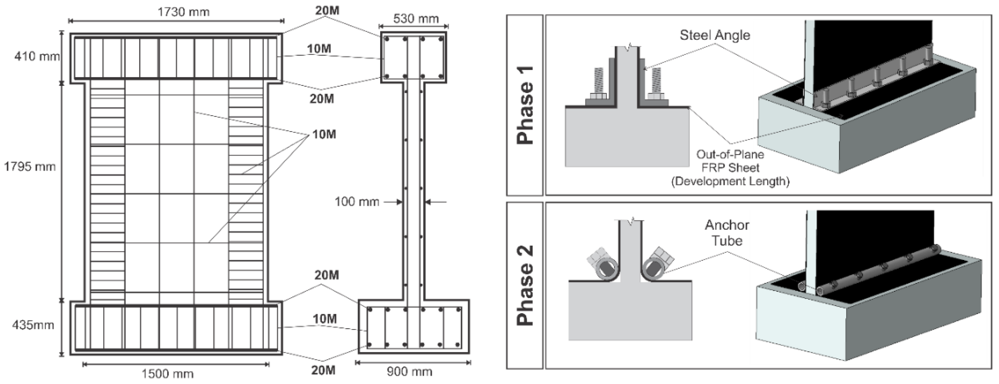
The first two phases of the test program examined the behaviour of flexural-critical RC shear walls retrofitted with CFRP sheets. The specimens had a height-to-width aspect ratio of 1.2 and were designed according to CSA A23.3 [30]. The key difference between the two phases of the experimental program was the type of anchor used to transfer the force from the CFRP sheets to the supporting foundation block. In the first phase, carried out by Lombard et al. [19], steel angles were used as the anchor for the CFRP sheets. The second phase examined the efficiency of a new type of anchor system developed by the research team, called the tube anchor system [20,31]. Figure 1 shows the specimen dimensions, reinforcement details, and the two anchor systems used in Phase 1 and 2. The strengthening and repair schemes implemented in these tests are listed in Table 1.
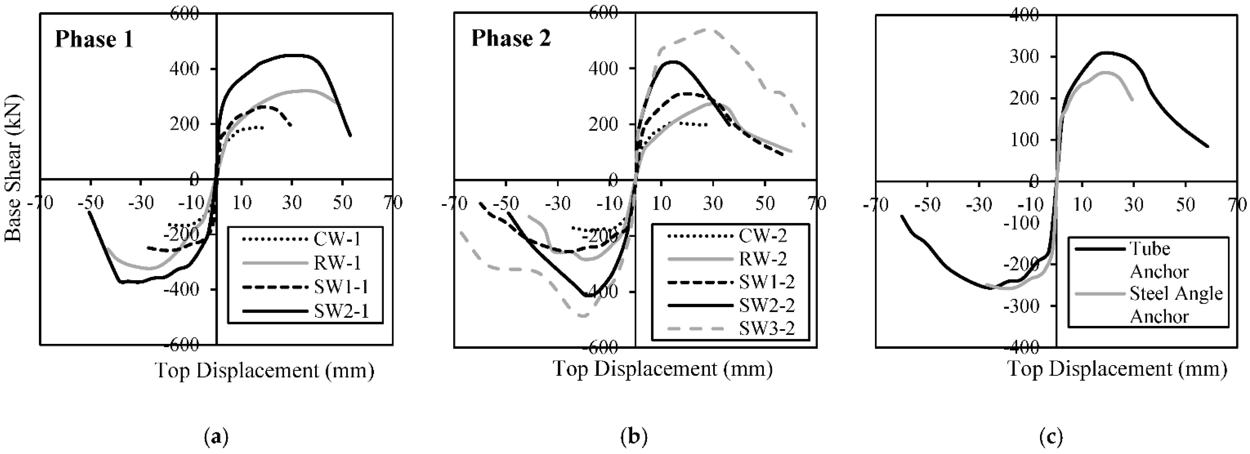
Figure 2 shows the envelopes of the hysteretic responses obtained from the two phases of the experimental study. It can be seen that the proposed CFRP repair strategies were able to regain most of the initial elastic stiffness and enhance the flexural capacity of the damaged walls. In strengthening applications (i.e., walls in as-built conditions), there was a significant increase in the stiffness and flexural capacity of the walls. Furthermore, it was found that using the new tube anchor system greatly improved the structural performance of shear walls. For walls with the conventional L-shaped steel angle anchor system, the CFRP sheets debonded from the concrete substrate prior to the CFRP material reaching its ultimate capacity. Premature debonding occurred despite providing the adequate development length for the CFRP sheets according to the ACI 440.2R guideline [32], which provides recommendations for the design and application of externally bonded CFRP systems.
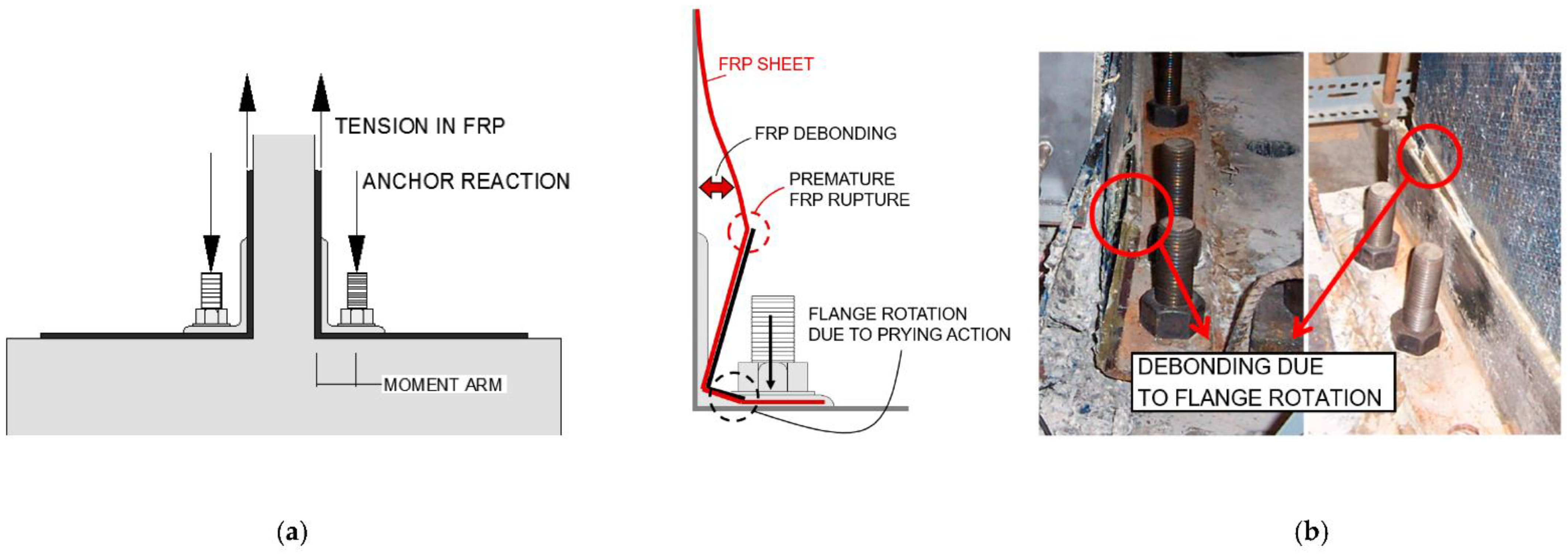
The main deficiency of the angle anchor system is the rotation and failure of the steel anchor, also known as “prying” action, caused by a moment due to the eccentricity between the tensile force in the CFRP sheet and the reactions of the anchoring bolts, as shown in Figure 3a. The prying action during the cyclic response of the shear wall results in debonding when the flange moves away from the surface of the wall, as illustrated in Figure 3b. When the direction of the load changes, the debonded CFRP sheet folds, which results in a fracture of the hardened epoxy matrix. The sharp edges made by the fractured CFRP sheet cut the CFRP fibres before it can reach its ultimate tensile capacity. This behaviour reduces the load resisting capacity of the shear wall.
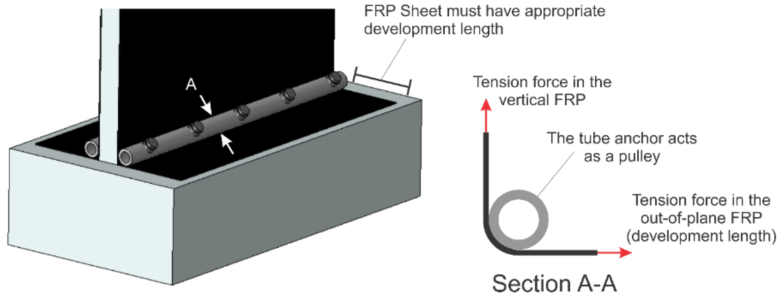
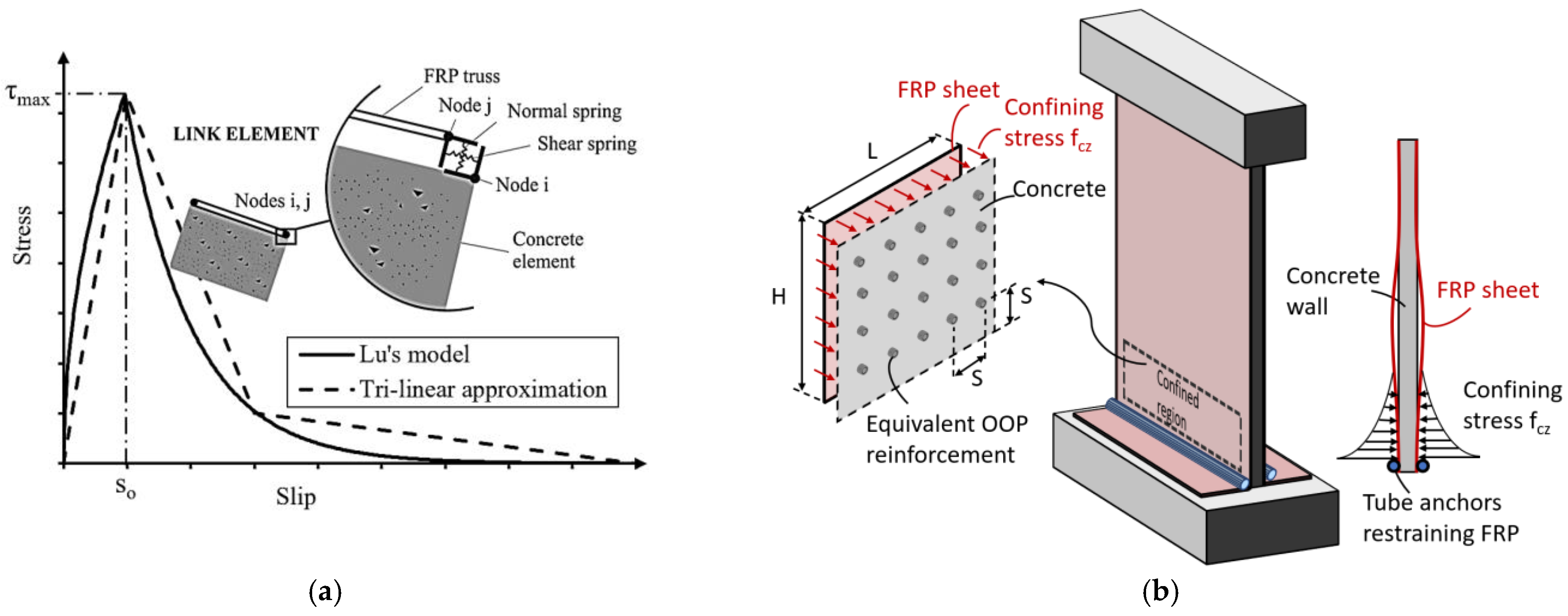
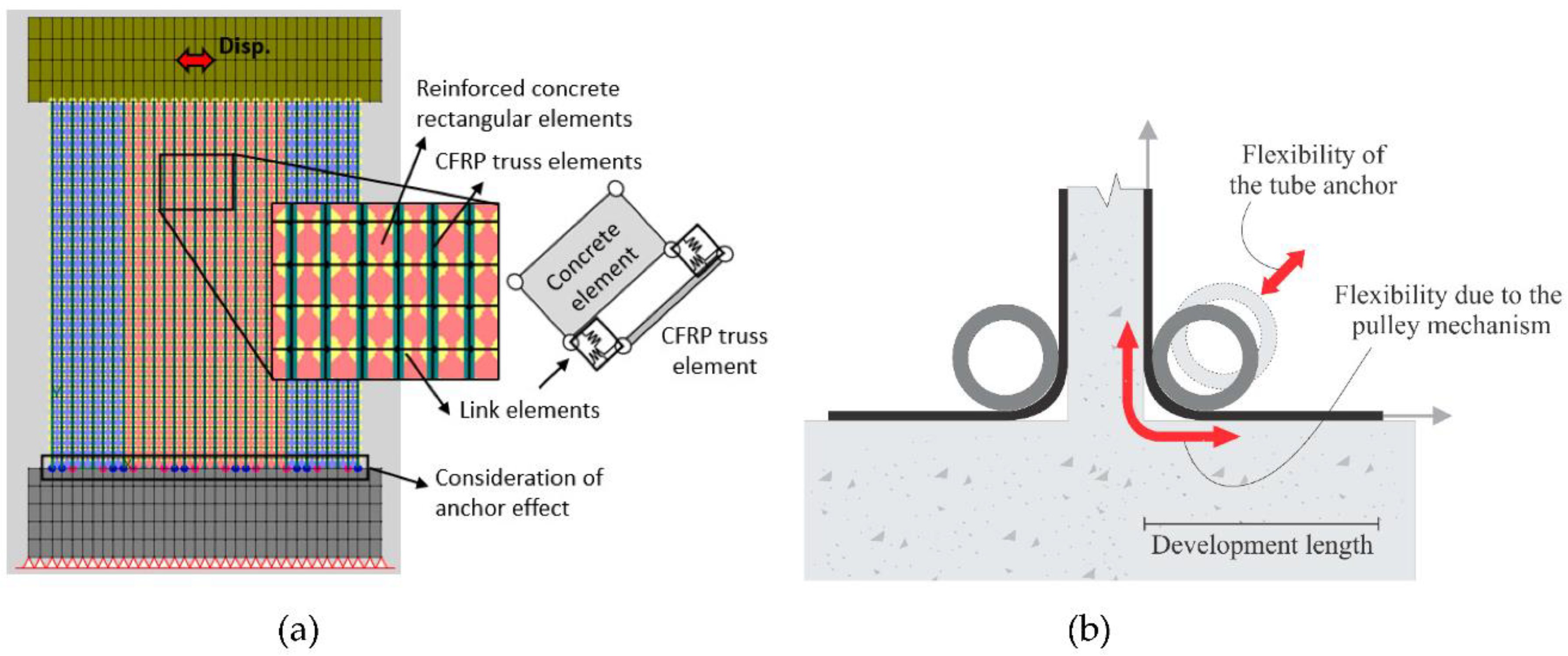
To prevent the prying action of the conventional steel angle anchor that results in premature debonding of the CFRP sheet, a novel tube anchor system was designed utilizing a cylindrical hollow section. For a tube anchor, the CFRP sheet is wrapped around the tube and attached to the adjacent members. The tube is anchored to the wall foundation using several threaded steel anchor rods at a 45-degree angle. Thus, the tube anchor has a loading mechanism similar to a pulley. The pulley principle is utilized in the design of the tube anchor. When the CFRP sheet is subjected to a tension load, the force in the vertical CFRP sheet is equal to the force in the out-of-plane CFRP sheet, which must have sufficient development length to transfer an equal force to the horizontal surface of the foundation block, as shown in Figure 4. The eccentricity between the forces carried by the CFRP sheets and the anchor bolts is eliminated by placing the anchor bolts in the direction of the resultant load. Figure 2c compares the response of two wall specimens which had identical design parameters, except one had the steel angle anchor system (SW1-1) while the other one had the tube anchor system (SW1-2). It can be seen that the wall with the tube anchor system demonstrated a higher capacity in terms of positive cycles and experienced a ductile failure with a gradual strength degradation in the post-peak response. The wall with the angle anchor system, on the other hand, experienced a brittle failure due to the premature rupture of CFRP sheets shortly after reaching its peak strength.

2.2. Phase 3: Application of Tube Anchor System to Shear-Critical Walls

Phase 3 of the experimental program investigated the effectiveness of the tube anchor system when applied to strengthen or repair walls with shear-critical behaviour. For this phase, Woods [33] tested seven RC shear wall specimens with aspect ratios of 1.2, 0.85, and 0.65 under in-plane reversed cyclic loads. Table 2 lists the characteristics of the specimens. The specimens were designed according to an older edition of CSA A23.3 [34] to represent typical nonductile shear walls which are susceptible to brittle shear failure in buildings constructed in 1960s and 1970s. Common structural deficiencies in these walls include insufficient shear reinforcement, poor confinement of the boundary elements, and low concrete compressive strength. An optimized version of the tube anchor was used in Series 1 and 2 of the test programme for the strengthening and repair of shear walls. Since there were no vertical CFRP layers in the Series 3 wall specimens of the Phase 3 tests, the new tube anchor system for the anchorage of vertical CFRP sheets was not required for these wall specimens.
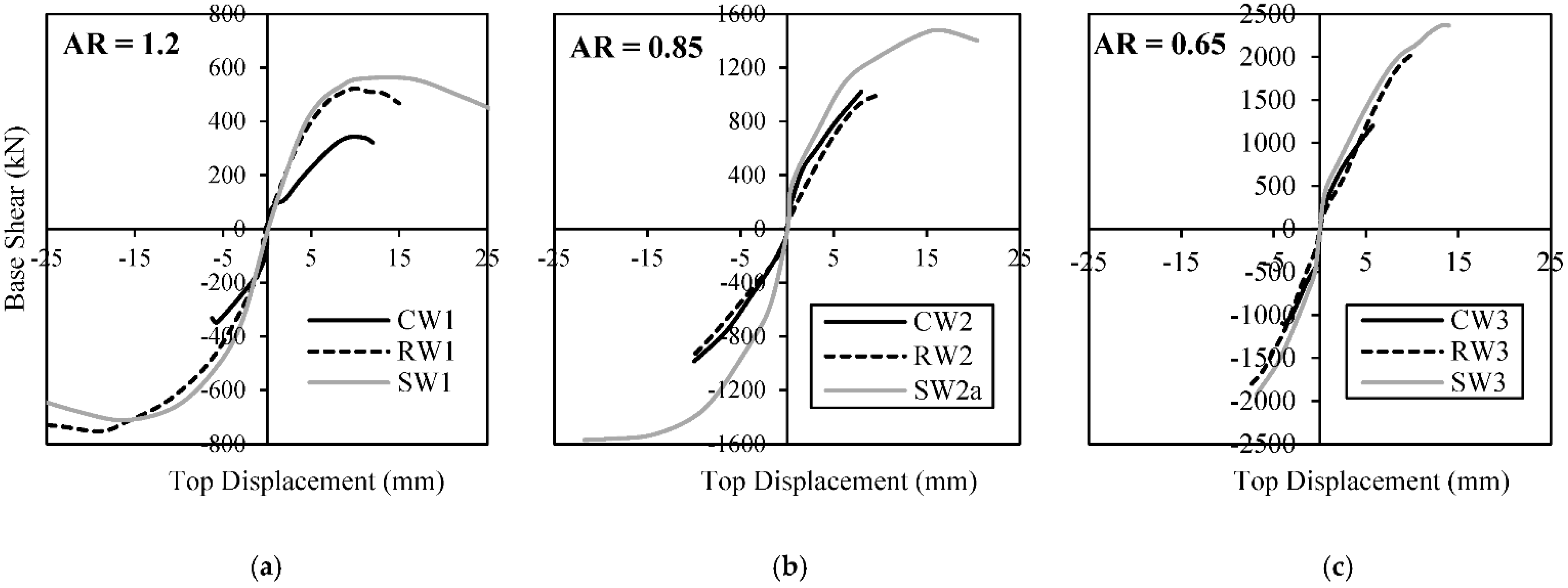
Figure 5 shows the envelopes of the hysteretic responses obtained from the tests. It can be seen that strengthening the walls enhanced their lateral load carrying capacity, ductility, and energy dissipation capacity. For repair applications, the retrofitted system was able to regain the original state of the wall specimen, demonstrating the effectiveness of the proposed repair strategy and the new tube anchor system when applied to non-ductile walls with shear-critical behaviour.

3. Proposed Modelling Method

In this study, a finite element (FE) modelling technique was developed for CFRP-strengthened RC shear walls that takes into account the effect of the anchor system on the structural response without requiring detailed micro-modelling of the anchor system. The FE models were developed using VecTor2, a 2D nonlinear analysis program specially developed for RC structures. VecTor2 is based on the Modified Compression Field Theory (MCFT) [35] and the Disturbed Stress Field Model (DSFM) [36]. The DSFM and MCFT are smeared rotating crack models that represent cracked concrete as an orthotropic material using a secant stiffness-based formulation. While the formulation is presented in terms of average stresses and strains within a macro-modelling framework, special considerations are given to the condition of the concrete at the crack locations to improve the accuracy of the models.

3.1. Modelling of an RC Shear Wall

Concrete was modelled using four-noded rectangular elements, and the reinforcing bars were added as a smeared component to the underlying concrete elements. Smeared modelling of reinforcement improved the efficiency of the model without affecting its accuracy, since both horizontal and vertical reinforcements were distributed uniformly along the height and length of the wall. Based on a mesh sensitivity analysis, it was found that a mesh size of 50 mm × 75 mm was suitable to capture damage in the shear wall while maintaining computational efficiency. Larger mesh sizes were used in the cap beam and the foundation block regions, since the behaviour was nearly rigid in those regions. The boundary condition at the bottom of the foundation block was assumed to be fully fixed. The lateral load was modelled by controlling the displacement of a node located at the centre of the cap beam, according to the loading pattern reported from the test. The self-weight of the wall was considered using gravity loads calculated based on the density of the concrete elements. The uniaxial behaviour of concrete was defined based on the measured uniaxial compressive strength values reported from the tests. The input parameters required to define the uniaxial behaviour of the reinforcement in the model were the yield and ultimate strength, initial elastic modulus, strain hardening strain, and ultimate strain. All these material properties were measured and reported in the experimental program.
Several material constitutive models were adapted from the literature to account for important mechanisms influencing the response of concrete and reinforcement. The pre- and post-peak compressive responses of concrete were modelled according to the Popovics and Mander models [37,38], respectively. The compression softening behaviour of concrete was considered using Vecchio’s model [39]. The tension stiffening and tension softening effects were computed with models developed by Fields and Bischoff [40] and Hordjik [41], respectively. The hysteretic behaviour of concrete was evaluated using a model proposed by Palermo and Vecchio [42], which follows a nonlinear unloading response for both tension and compression and is capable of computing plastic strains due to internal damage. The hysteretic response of reinforcement was calculated using the Seckin [43] model, which accounts for the Bauschinger effect. The Akkaya et al. [44] model was employed to capture any potential buckling effects in the reinforcement under compression. Figure 6 shows the material models used to calculate the response of concrete and reinforcement.

3.2. Modeling of CFRP Sheets

3.2.1. Bond–Slip Behaviour

In strengthened and repaired walls subjected to lateral loads, vertical CFRP sheets typically experience higher tensile stresses than horizontal CFRP sheets and are therefore more prone to debonding from the concrete substrate. To capture the debonding of the vertical CFRP sheets and accurately represent their tension stiffening effect, they were explicitly considered in the FE model using tension-only truss elements. To improve the computational performance of the model and make it more practical for engineering applications, the horizontal CFRP layers, which are less critical, were added to the model as a smeared component of the underlying concrete elements. The area of the vertical CFRP trusses was calculated based on the thickness, number of layers, and tributary width of the CFRP sheets. The stress–strain relation in the CFRP material was assumed to be linear elastic until rupture of CFRP. The uniaxial behaviour of CFRP was defined based on its ultimate strength and elastic modulus, as reported from the tests. The tension stiffening and crack control effects of CFPR were considered using the Sato and Vecchio model [45]. This model computes the crack spacing and the contribution of CFRP to the tensile strength by formulating the equilibrium at the crack location.
Link elements were used at the interface of the RC rectangular elements and CFRP truss elements to represent the bond–slip relationship between the CFRP and concrete. The link element is a two-noded, zero-length element with four translational degrees-of-freedom. The interaction between the two nodes of a link element is represented by two springs: the “shear” spring, which acts along the longitudinal axis of the CFRP truss, and the “normal” spring, which acts in the direction of the orthogonal axis, as illustrated in Figure 7a and Figure 8a. The shear spring was used to represent the bond–slip behaviour, while a very large stiffness value was assigned to the normal spring to prevent any movement in the orthogonal direction. The tri-linear approximation of the bond–slip model proposed by Lu et al. [24] was employed in which the relation between shear stress and slippage was derived from CFRP-concrete pull tests. This bond–slip relationship is defined by the following equation:
τ = { τ m a x s s 0                                         i f   s s 0 τ m a x . e α ( s s 0 1 )                     i f   s > s 0
where τmax is the maximum shear stress and s 0 is the interfacial slip corresponding to τmax. These two parameters can be determined from Equations (2) and (3).
τ m a x = 1.5   β w f t
s 0 = 0.0195   β w f t
where ft is the tensile strength of concrete and βw is a factor representing the FRP-to-concrete width ratio as expressed in Equation (4).
β w = 2.25 b f b c 1.25 + b f b c
where bf and bc are the width of the FRP strip and the concrete member, respectively. The last parameter in Equation (1) is the α factor, which is a function of the interfacial fracture energy (Gf) and can be determined using Equations (5) and (6).
α = 1 G f τ m a x s 0 2 3
G f = 0.308   β w 2 f t
Based on the above equations, the maximum bond shear stress (τmax) was calculated to be 3.69 MPa and 1.73 MPa for the strengthened shear walls tested in Phase 2 and Phase 3, respectively. The corresponding slip ( s 0 ) at the maximum bond shear stress was found to be 0.050 mm and 0.022 mm for these two phases.

3.2.2. Confinement Effect

The numerical models in this study are two-dimensional, and there is a need to consider the out-of-plane (OOP) effect of the externally bonded CFRP sheets; hence, an independent analytical parametric study was conducted using the Abaqus program to investigate the OOP confining effect of CFRP layers on the concrete. Three-dimensional numerical shear wall models having different aspect ratios, numbers of CFRP layers, and thicknesses in the horizontal and vertical directions were subjected to axial compression loading. By calculating the difference between the average OOP stresses in the concrete elements of models with and without the CFRP layers, it was found that there is a considerable concrete confinement effect in the CFRP-strengthened shear walls that can affect the structural response. From the parametric study, it was concluded that as the thickness or the aspect ratio of the wall increases, the OOP compressive stresses in concrete—and as a result, the confinement effects due to CFRP—decreases. The analysis results also showed that the confinement effects vary along the height of the wall, being greatest near the anchor. In this region, the concrete cannot expand in the OOP direction, since it is fully confined by the tube anchors on both sides. As the section moves away from the anchors, the degree of concrete confinement reduces considerably. Figure 7b shows a schematic distribution of confining stresses in concrete along the height of the wall resulting from the CFRP sheets anchored at the bottom of the wall.
To consider the confinement effect of the CFRP sheets in the two-dimensional model, an equivalent amount of OOP steel reinforcement was computed and added to the concrete elements. VecTor2 increases both the uniaxial compressive strength and the corresponding strain of concrete by a confinement enhancement factor (βl) proposed by Kupfer et al. [46] and expressed in Equation (7). The βl factor is a function of the triaxial stress state in concrete, which depends on the ratio and properties of the OOP reinforcement.
β l = [ 1 + 0.92 ( f c n f c ) 0.76 ( f c n f c ) 2 ] + 4.1 ( f c l f c )
In Equation (7), fcl is the lateral confining stress and fcn is the difference in normal lateral stresses acting on the concrete, both determined from the in-plane and OOP stresses in concrete. The in-plane stresses are calculated from the two-dimensional analysis, while the OOP stress (fcz) can be estimated from the OOP strain (εcz) based on the following equation.
ε c z = E c E c + ρ z E s z ( υ 12 f c 2 E ¯ c 2 υ 21 f c 1 E ¯ c 1 )
where ρ z and E s z are the ratio and elastic modulus of the OOP reinforcement, E c is the elastic modulus of concrete, f c 1 and f c 2 are the principal stresses in concrete, υ 12 and υ 21 are the Poisson’s ratios of concrete in the principal directions, and E ¯ c 1 and E ¯ c 2 are the secant stiffness moduli in the principal directions as determined from the MCFT model.
The application of Equations (7) and (8) requires estimating the equivalent OOP reinforcement ratio that represents the confinement effect of the CFRP sheets. The ratio of the OOP reinforcement can be calculated by equating the force resulting from the confining stresses in concrete with the yielding force of the OOP reinforcement over an arbitrary area of h × L, as shown in Figure 7b and expressed in Equation (9).
f c z · h · L = ( A s z · F y z ) (   L s   ) (   h s   )
where A s z , F y z , and s are the cross-sectional area, yield strength, and spacing of the OOP reinforcement, respectively. The reinforcement ratio can be written in terms of the area of concrete and reinforcement, as expressed in Equation (10).
ρ z = A s z A c = A s z · ( L s   ) · ( h s   ) L · h = A s z s 2
By substituting Equation (10) into Equation (9), it can be shown that the ratio of the OOP concrete stress ( f c z ) to the reinforcement yield strength ( F y z ) equals to the ratio of the OOP reinforcement ( ρ z ) that represents the confinement effect of the CFRP sheets.
ρ z = f c z F y z
Based on the parametric study conducted using the three-dimensional shear wall model, it was found that, on average, the OOP compressive stress that developed in concrete due to CFRP is 3.5 MPa. Assuming a yield strength of 400 MPa for the reinforcement, the equivalent OOP reinforcement ratio is calculated from Equation (11) to be 0.9%. This OOP reinforcement ratio was added to the concrete elements located at the bottom third of the wall, where the confinement effect is significant. For these elements, VecTor2 calculates the βl enhancement factor using Equations (7) and (8) and increases their strength and ductility to account for the confinement effect. The 0.9% ratio is only appropriate for walls with design parameters within the range investigated in this study. Future work is needed to develop relationships to predict OOP compressive stress in concrete for other wall geometries and CFRP strengthening schemes.

3.3. Modeling of Tube Anchor Effects

As explained earlier, the anchor system is a critical component in the design of a CFRP strengthening system; therefore, special attention should be paid to including the influence of this component in the numerical model. When using the tube anchor system, there are two sources of flexibility at the junction of the wall and foundation that need to be considered: (1) flexibility due to the pulley mechanism, which is a function of the development length of the CFRP in the OOP direction; and (2) the flexibility of the anchor, which depends on the stiffness of the tube, as shown in Figure 8b.
Two different approaches were followed to model the flexibility of the vertical CFRP sheets due to the pulley mechanism of the tube anchor. In the first approach, a perfect bond was assumed between the CFRP trusses and concrete elements at the anchor bolt locations of the tube anchor (i.e., a common node was used to connect the two elements); whereas over the interval between adjacent anchor bolts, link elements having different bond–slip relationships representing the flexibility of the anchor system were used to connect the CFRP trusses to concrete elements. In the second approach, all nodes of the CFRP trusses and concrete elements at the junction of the wall and foundation block were directly connected to each other using common nodes (i.e., prefect bond assumption); however, truss elements were used to model groups of uniaxial elastic springs with different stiffnesses over the interval regions between the anchor bolts to simulate the influence of the OOP CFRP on the foundation block. The elastic modulus of the springs was selected such that they had higher stiffness values near the bolts and lower values further away from the bolts. For simplicity, from now on, the first approach will be referred to as “Model A” and the second approach will be referred to as “Model B”. Figure 9 shows the configuration of link and truss elements used to consider the flexibility of vertical CFRP sheets due to the pulley mechanism of the tube anchor.
In both modelling approaches, the parts of the anchor tube between the bolts were assumed to act as a pulley that transfers the load from the in-plane vertical CFRP connected to the wall to the OOP CFRP attached to the top of the foundation block. Based on the concept of a pulley, the force developed in the OOP CFRP sheets should be equal to the force in the vertical CFRP sheets at the junction of the wall and foundation block. To determine the bond–slip relationship of link elements used in Model A and the stress–strain relationship of truss (spring) elements used for Model B, a small section of the OOP CFRP was separately modelled in VecTor2, as shown in Figure 9. The length of the OOP CFRP model was equal to 350 mm, i.e., the development length of CFRP sheets reported in the experimental program. The width of the OOP CFRP model was taken as the tributary width of the CFRP truss elements used for the shear wall model. In order to obtain a more accurate response, a finer mesh was used in the OOP CFRP model compared to the shear wall model. All nodes located at one end of the model were restrained against translational movements in the x and y directions, while nodes at the other end were subjected to horizontal displacements representing the deformations of the CFRP sheets. For the first modelling approach (Model A), the force-displacement relationship resulting from the OOP CFRP model was transformed to an equivalent bond–slip relationship and assigned to link elements defined at the junction of the wall and foundation block. The bond stress was calculated by dividing the force by the tributary area of link elements, and the slippage was taken equal to the displacement applied to the model. For the second modelling approach (Model B), the force-displacement relationship of the OOP CFRP model was converted to an equivalent stress–strain relationship and assigned to truss elements simulating the flexibility of the anchor system. The stress was determined by dividing the force by the cross-sectional area of truss elements, while the strain was computed by dividing the displacement by the element’s original length.
As mentioned earlier, in addition to the pulley mechanism, the flexibility of the tube anchor can also influence the force distribution in the CFRP sheets at the base of the wall and consequently affect the response of strengthened/repaired wall. To account for this effect, a triangular force distribution was assumed along the tube anchor which represented an idealized loading condition that CFRP sheets experience under lateral loads due to earthquake. In this distribution, the maximum force value was assumed to be the rupture strength of CFRP which occurred at the tensile side of the wall, while the force value at the compression end of the wall was taken as zero. As shown in Figure 9, one span of the tube anchor between the bolts was analysed as a simply supported beam under the idealized force distribution. The resultant deflection (d) was then added to the force-displacement relationship of the tube anchor as an additional source of flexibility and considered in the calculation of the equivalent bond–slip and stress–strain relationships used in Model A and Model B, respectively.

4. Verification Study

To evaluate the accuracy of the proposed modelling approach, all the control and CFRP-strengthened shear walls (with the tube anchor system) discussed in 
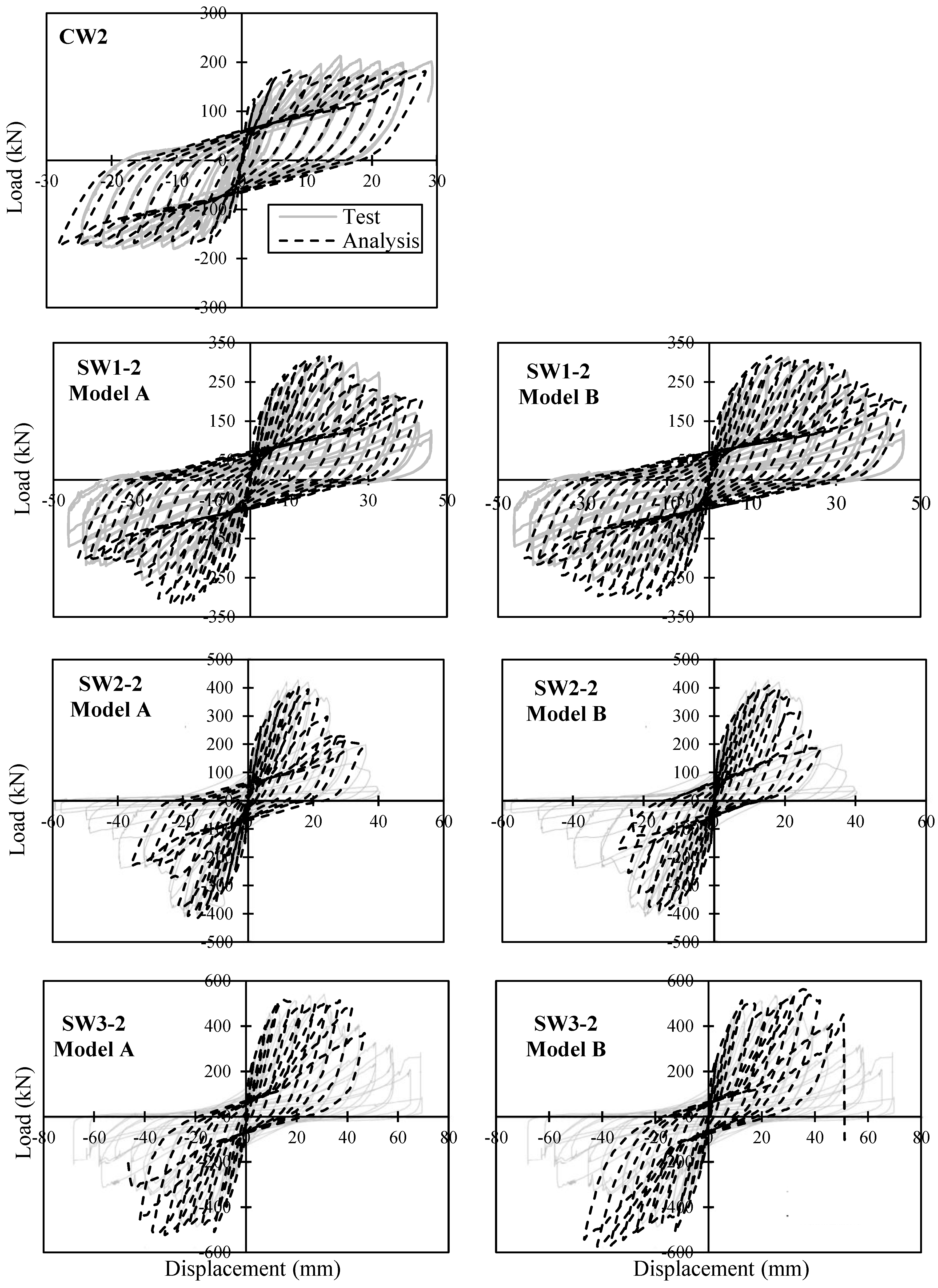
Section 2 were analysed and their load-deflection responses and failure modes were compared against those reported from the experiment. The analytical and experimental hysteretic responses of shear walls tested in Phase 2 are plotted in 
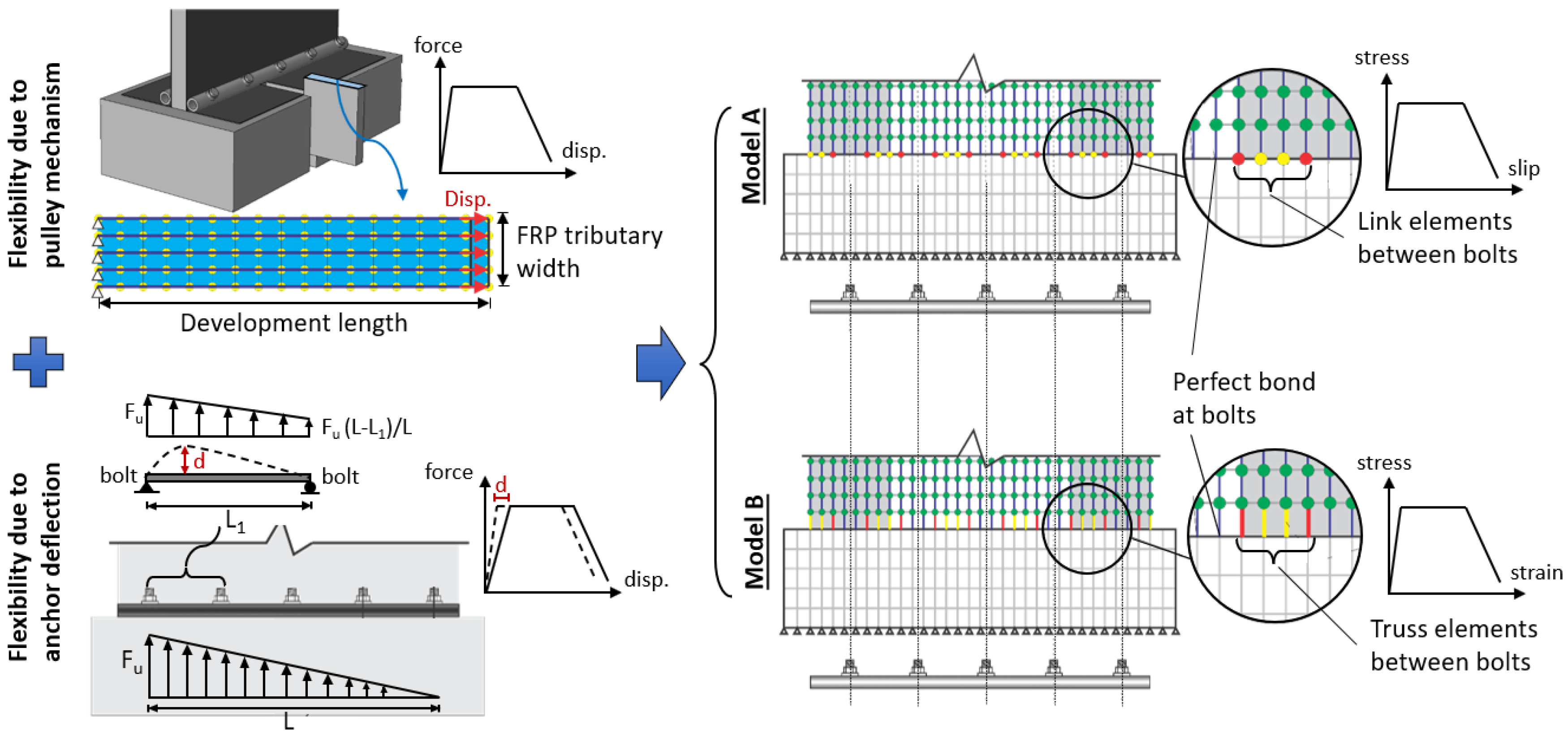
Figure 10. In general, the computed results of both Model A and Model B agreed quite well with the measured responses considering the complexity of the problem. The numerical models were able to accurately capture the strength degradation and the pinching effect. The initial stiffness and the pre-peak behaviour were well predicted. The ductility and energy dissipation capacity of the strengthened walls were slightly underestimated due to rupture of the vertical steel reinforcement in the numerical models, leading to termination of the analyses prior to the experimental tests.
Table 3 compares the sequence of damage for the Phase 2 shear walls obtained from the analytical models and experimental tests. It can be seen that both Model A and Model B were able to capture the damage sequence with good accuracy. All CFRP-strengthened specimens more or less experienced the same damage sequence. First, the extreme flexural steel reinforcement was yielded which resulted in higher stress on the CFRP sheets and consequently debonding of it from concrete near the bottom edges of the wall. The concrete then started to crush at the toes of the wall which led to reduction in the lateral load carrying capacity of the shear wall. Finally, the CFRP sheets reached their rupture strength capacity in tension which in combination with the extensive crushing of the concrete in compression resulted in complete failure of the shear wall. As shown in Table 3, the proposed modelling approach predicted the displacement and force associated with the yielding of reinforcement, debonding of CFRP and crushing of concrete reasonably well. The displacement associated with the CFRP rupture was overestimated, while the corresponding force was slightly underestimated.
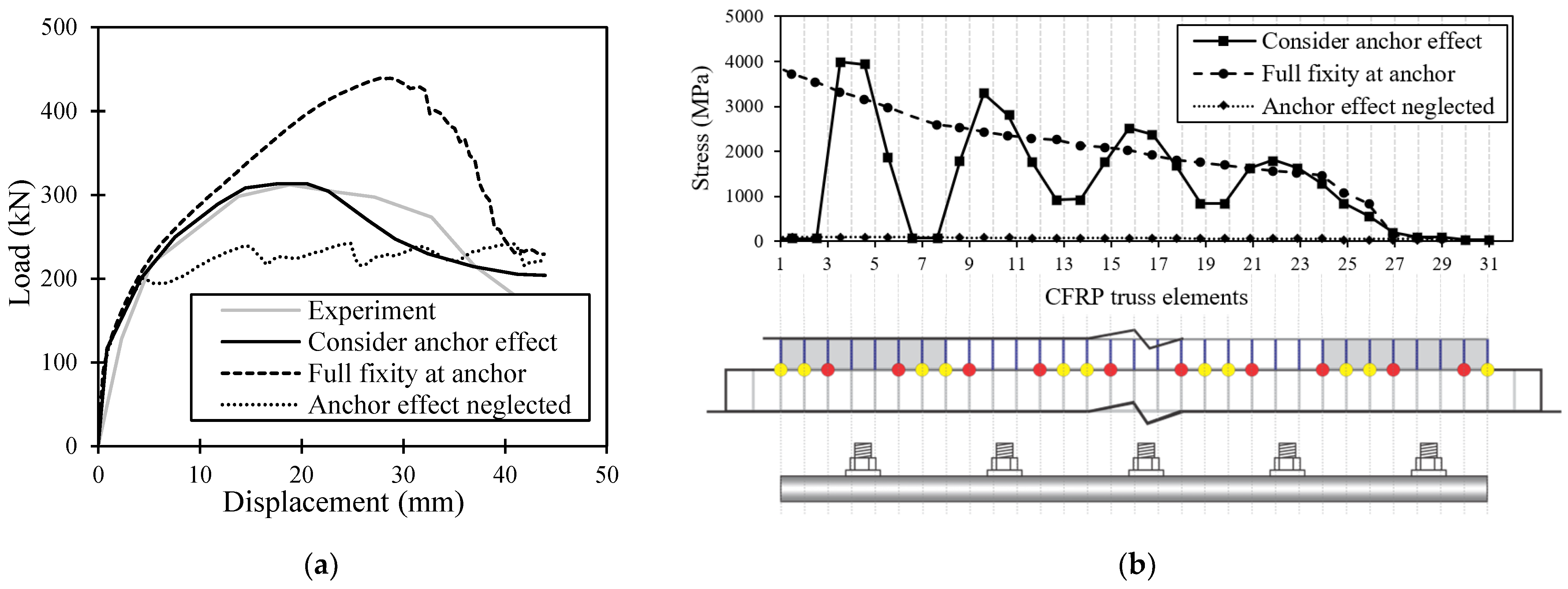
To demonstrate the importance of considering the effect of tube anchor in the FE model, two additional analysis cases were performed on the SW1-2 wall. For the first analysis case, prefect bond was assumed for all nodes at the junction of the wall and foundation block (i.e., CFRP trusses and concrete elements were connected using the same nodes). This analysis case represents the typical assumption that engineers and researchers make when modelling the effect of anchor system on CFRP strengthened/repaired RC structural elements. They often assume that the anchor system provides full fixity for the CFRP sheets and ignore any flexibility at the base. For the second analysis case, the contribution of the anchor system was neglected and only the bond interaction between the CFRP sheets and concrete substrate was considered using link elements.
Figure 11a compares the experimental response of SW1-2 against the analytical responses obtained from the Analysis Case 1 (assume full fixity at the base), Analysis Case 2 (neglect the anchor effect), and Model A (consider the anchor effect using the proposed modelling approach). Figure 11b also demonstrates the stress distribution in the CFRP truss elements at the base of the SW1-2 wall calculated by the three modelling approaches. It can be seen from Figure 11a that the peak loads calculated by both Analysis Case 1 and 2 were significantly different from the measured result. Assuming the anchor system was rigid and fully restrained CFRP sheets at the base greatly overestimated the capacity of the wall and served as an upper bound load capacity. On the other hand, neglecting the contribution of anchor system and only relying on the bond strength between the CFRP sheets and concrete as the force transfer mechanism at the base resulted in significant underestimation of the capacity. In comparison, the use of Model A, which properly considered the influence of the anchor system, including the deformations of the tube anchor and the OOP CFRP sheet, resulted in much better predictions of the load-deflection response. As shown in Figure 11b, Model A was able to capture the stress concentration in vertical CFRP sheets at bolt locations, as well as the reduction of stress between the bolts due to the flexibility of the anchor system. The more realistic prediction of the CFRP stress distribution at the base enabled Model A to calculate the load capacity of the strengthened wall with better accuracy compared to the Analysis Case 1 and 2 which are based on commonly used modelling assumptions in practice.
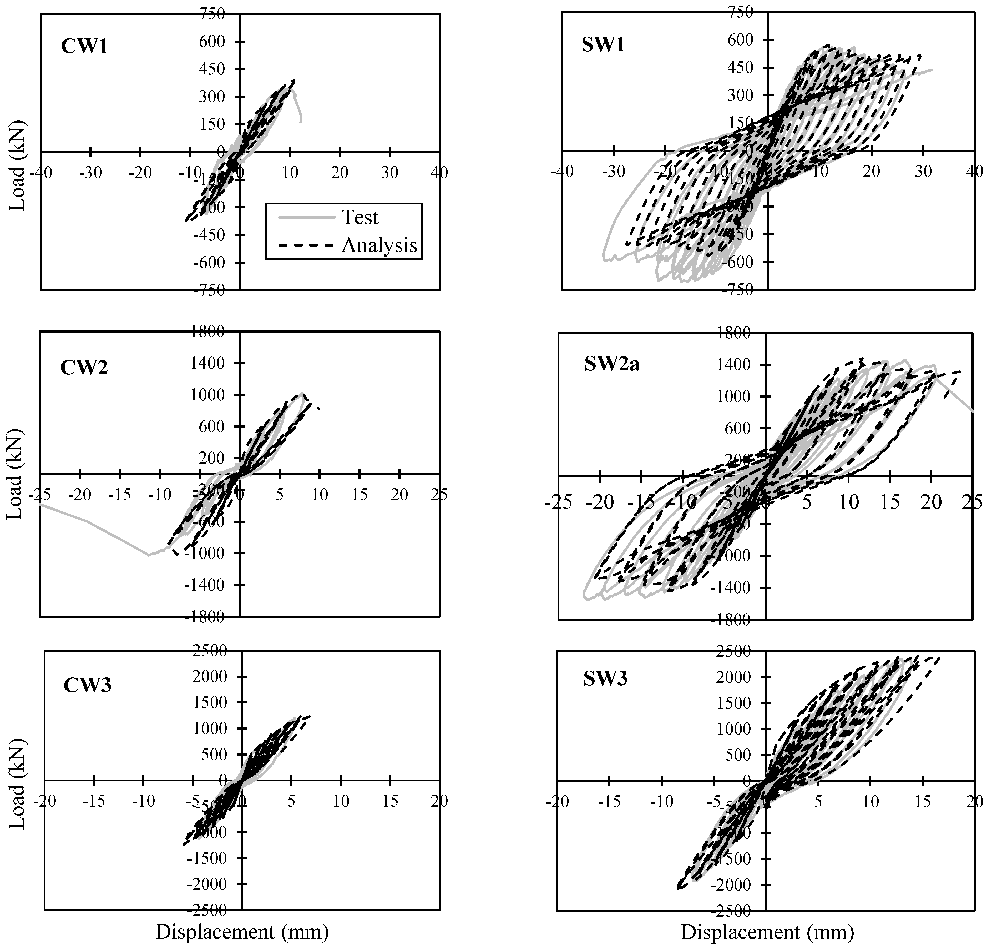
Figure 12 shows the computed hysteretic responses versus the experimental results of shear walls from Phase 3 of the test program. Based on the analytical responses obtained from Phase 2, both modelling approaches (Model A and Model B) result in similar responses. Therefore, Phase 3 shear walls were analysed using only the Model A approach. As shown in 
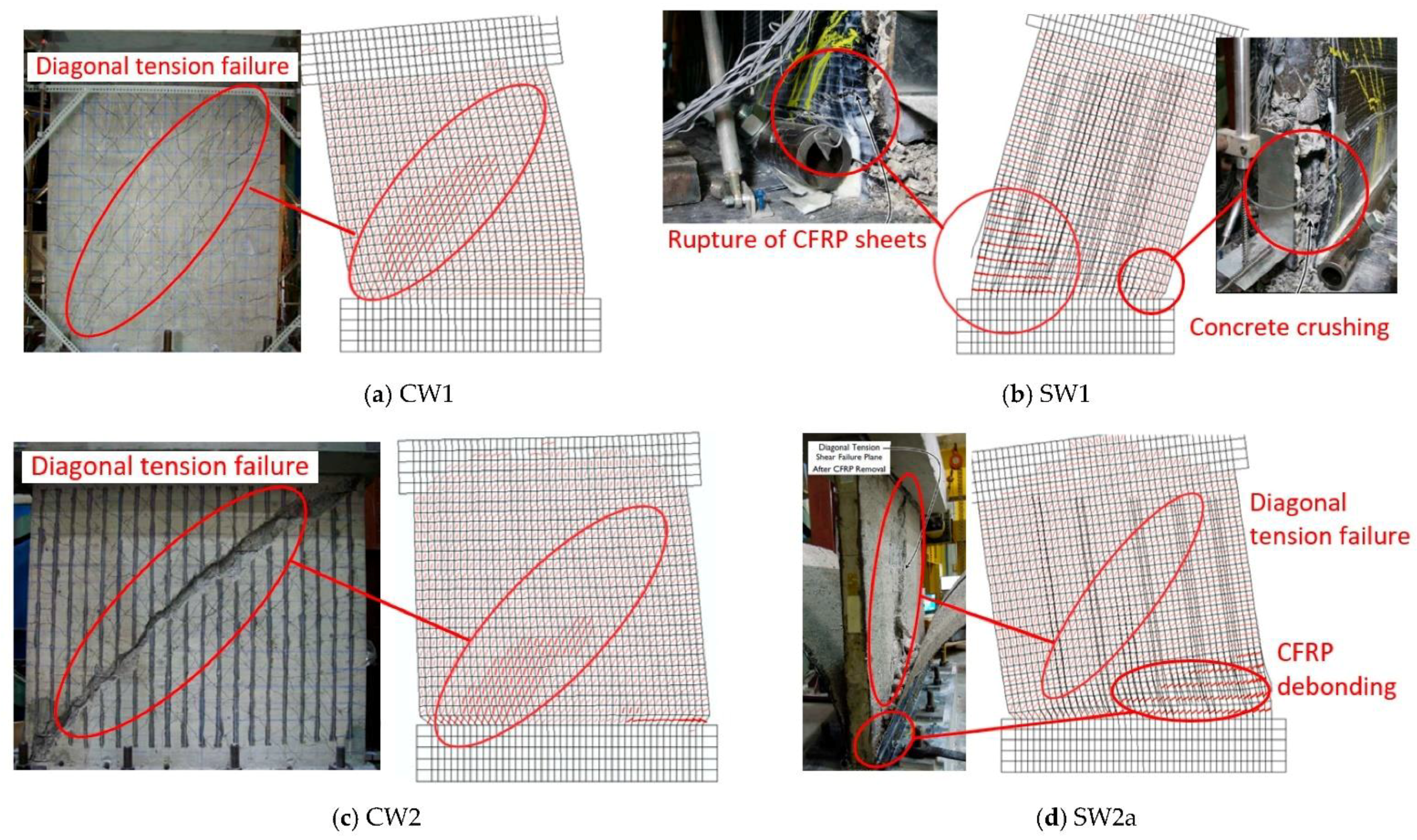
Figure 12, generally there was a good correlation between the analytical and experimental results in terms of the initial stiffness, peak load, and ductility. However, the pinching effect in control walls (CW1, CW2, and CW3) was overestimated. Also, the peak load of SW1 and SW2a strengthened walls was better predicted in the positive cycles compared to the negative cycles. The experimental response of these walls was asymmetrical which could be due to slight shifting of the reinforcing steel rebar assemblies during the construction process of the wall specimens. Considering that the FE model was symmetrical similar responses were computed under the positive and negative cycles. The small difference between the positive and negative responses of the FE model was because of the strength degradation and damage computed in the prior cycles. Unlike the SW1 and SW2a strengthened walls which were subjected to symmetrical loading protocols, the SW3 strengthened wall had an unsymmetrical loading condition. For this wall, first a reversed-cyclic load was applied in both the positive and negative directions, which was then followed by a cyclic load only in the positive direction until the wall failed. Using the same loading protocol for the numerical model resulted in a load-deflection response that correlated very well with the experimental results. It is also worth mentioning that the proposed modelling approach was able to accurately predict the increase in peak load and ductility capacity of all three control walls which had different aspect ratios when strengthened with CFRP sheets.
Figure 13 compares the observed and calculated failure modes of the control and strengthened shear walls of Phase 3. It can be seen that both the CW1 and CW2 control walls experienced a brittle diagonal tension failure which occurred after rupture of the horizontal steel reinforcement due to high shear stresses. The FE model was able to capture the extensive diagonal cracks in the concrete and the formation of a wide crack close to the centre which led to the diagonal tension failure of the wall. Based on the test results, the vertical reinforcement of CW1 and CW2 reached the yielding strain at the lateral load of 242 kN and 762 kN, respectively. The FE model calculated the yielding loads of CW1 and CW2 to be 325 kN and 810 kN, respectively. Similar to the test results, the FE model predicted rupture of the horizontal reinforcement prior to the failure of both walls.
The average ratio of the analytical-to-experimental peak strength for the control and strengthened specimens analysed in this study were 1.02 and 0.99, respectively. The coefficient of variation of this ratio for the control and strengthened specimens were 9.1% and 6.1%, respectively. The ratio of the analytical-to-experimental load corresponding to the debonding of CFRP sheets had a mean and coefficient of variation of 1.08 and 15%, respectively.
The SW1 wall experienced a very ductile response which was mainly because of the significant yielding occurred throughout the vertical reinforcing steel bars prior to the failure. Both the test and analysis results showed that addition of the vertical and horizontal CFRP sheets prevented the diagonal tension failure in this wall enabling it to achieve significantly higher lateral load and ductility compared to the CW1 wall. After the yielding of vertical reinforcing bars, there was a considerable increase in stresses of the vertical CFRP sheets which led to deboning and eventually rupture of CFRP. Due to the lack of confinement in the boundary elements, SW1 also experienced concrete crushing at the toe region which contributed to its failure. As shown in Figure 13, the FE model was able to capture the debonding and rupture of the vertical CFRP sheets as well as the crushing of concrete at the toe. Similar to the SW1 wall, the SW2 wall also showed a ductile response with considerable yielding in the vertical steel reinforcement. However, because of its lower aspect ratio this wall was subjected to higher shear stresses and experienced a diagonal tension failure after debonding of the CFRP sheets. The addition of the CFRP sheets enabled the SW2 wall to reach its flexural capacity prior to failure and show significant improvement in terms of ultimate displacement and lateral strength compared to the CW2 wall. The FE model accurately predicted the damage sequence of this wall including the yielding of vertical steel reinforcement, deboning of CFRP sheets, and extensive diagonal cracking in concrete which eventually resulted in the failure of the wall. The CW3 and SW3 walls were not included in Figure 13 since they did not experience any major damage and failed prematurely in the foundation block.

5. Summary and Conclusions

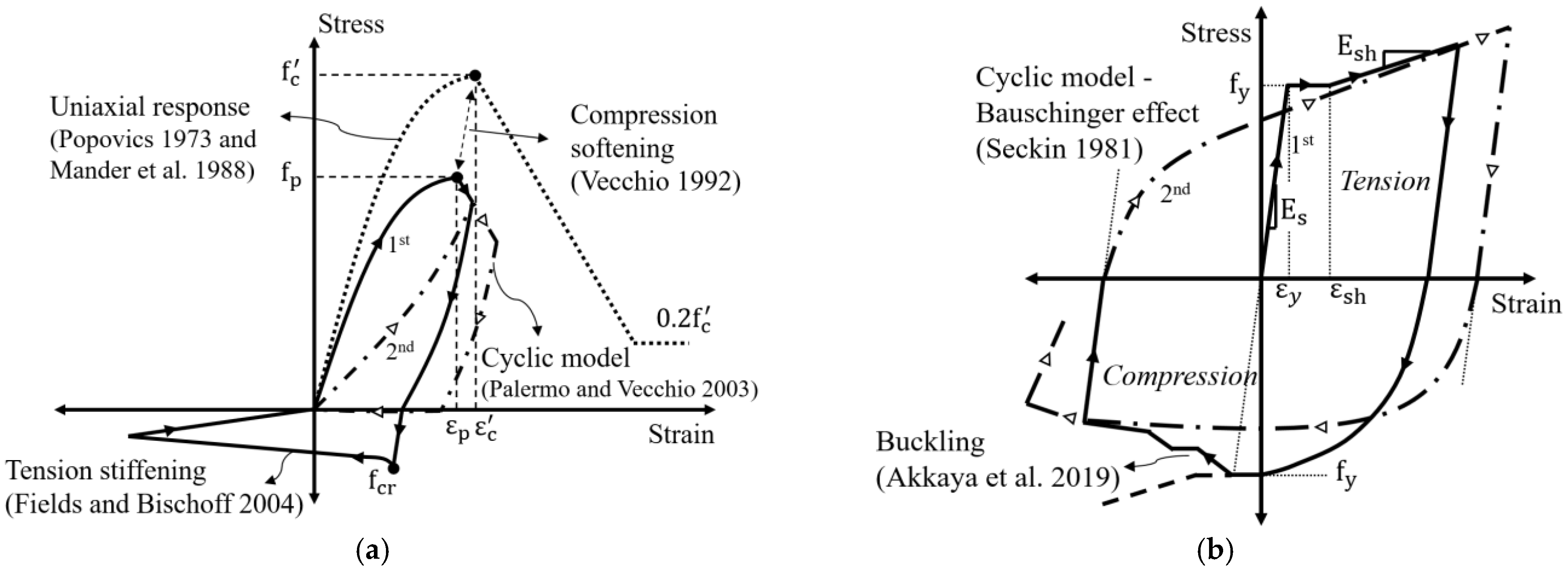
This paper first presented an overview of a comprehensive experimental program conducted over the last twenty years at Carleton University which has led to the development of a novel tube anchor system for CFRP-strengthened or repaired RC shear walls. The test results demonstrated the efficiency of the tube anchor system to prevent premature debonding of CFRP allowing it to achieve its full tensile capacity. This study developed the first numerical model that carefully accounts for the influence of the tube anchor system on the response of the CFRP-strengthened shear walls. Two approaches were proposed to consider the complex behaviour of the tube anchor without requiring detailed modelling of it. The flexibility of the tube anchor due to the pulley mechanism as well as deformation of the tube itself was quantified and considered in the FE model. Moreover, the confinement effect of CFRP layers on concrete near the anchor region was taken into account based on an independent parametric study. Also, second-order material effects such as compression softening, tension stiffening and bond–slip effects between CFRP and concrete were considered in the analysis by adapting appropriate models from the literature. To assess the accuracy of the proposed modelling methods, four control RC shear walls and six CFRP-strengthened shear walls were analysed. Based on the comparison of the analytical and experimental results, the following conclusions can be drawn:
  • The proposed FE modelling methods were able to accurately compute the key structural response parameters of CFRP-strengthened shear walls including the initial stiffness, peak strength, and ductility under cyclic loads. The FE models were also able to predict the damage sequence and crack patterns of the walls reasonably well.
  • It was shown that oversimplifying the effect of development length and anchor system, using assumptions such as uniform perfect or imperfect bond between CFRP and concrete at the base of the wall, can lead to significant overestimation or underestimation of the peak strength. Consideration of the effects of the anchor system in the analytical model was found to be critical for a reliable prediction of the nonlinear performance of shear walls reinforced with CFRP sheets.
  • The analysis results showed that the confining effect of CFRP sheets near the anchor region was more significant for walls with smaller aspect ratios. Modelling the confining effect played an important role in capturing the ductility capacity of the walls.
  • It was also found that accounting for the effect of anchor system was essential for capturing the nonlinear stress distribution in CFRP sheets near the base specially the stress concentration at bolt locations. This stress concentration ultimately led to debonding and rupture of CFRP sheets after the CFRP has developed its full tensile capacity.
Rational two-dimensional modelling procedures such as the ones presented in this study enable engineers and researchers to take into account the effects of the anchor system with reasonable accuracy without requiring three-dimensional modelling of shear walls or using highly detailed models with extremely fine finite element meshes. These relatively simple macro-modelling methods are expected to be highly beneficial for engineering offices to tackle the complex problem of assessing safety and performance of CFRP-strengthened structures. Future research is needed to examine the applicability of the proposed modelling methods to analysis of damaged or deteriorated shear walls repaired with CFRP sheets. The application range of the proposed modelling methods also needs to be extended to other commonly used anchor systems available in the literature. Another area that needs further research is to improve the efficiency of anchor system designs for RC shear walls with different aspect ratios and CFRP strengthening schemes. This can be achieved by conducting a comprehensive parametric study using the proposed modelling methods to understand and quantify the effect of different design parameters of the anchor system on the performance of strengthened shear walls.

Author Contributions

Model development: S.A.S., V.S. and D.L.; Model validation: S.A.S. and V.S.; Investigation of results: V.S., D.L. and S.A.S.; Writing: V.S.; Review and editing: D.L. and S.A.S.; Funding acquisition: D.L. All authors have read and agreed to the published version of the manuscript.

Funding

This research was funded by the Natural Science and Engineering Research Council Canada (NSERC).

Data Availability Statement

Not applicable.

Conflicts of Interest

The authors declare no conflict of interest.

References

  1. Xian, G.; Guo, R.; Li, C.; Wang, Y. Mechanical performance evolution and life prediction of prestressed CFRP plate exposed to hygrothermal and freeze-thaw environments. Compos. Struct. 2022, 293, 115719. [Google Scholar] [CrossRef]
  2. Wei, Q.; Zhu, L.; Zhu, J.; Zhuo, L.; Hao, W.; Xie, W. Characterization of impact fatigue damage in CFRP composites using nonlinear acoustic resonance method. Compos. Struct. 2020, 253, 112804. [Google Scholar] [CrossRef]
  3. Guo, R.; Li, C.; Xian, G. Water absorption and long-term thermal and mechanical properties of carbon/glass hybrid rod for bridge cable. Eng. Struct. 2023, 274, 115176. [Google Scholar] [CrossRef]
  4. Rajak, D.K.; Wagh, P.H.; Linul, E. Manufacturing technologies of carbon/glass fiber-reinforced polymer composites and their properties: A review. Polymers 2021, 13, 3721. [Google Scholar] [CrossRef]
  5. Jahami, A.; Temsah, Y.; Khatib, J.; Baalbaki, O.; Kenai, S. The behavior of CFRP strengthened RC beams subjected to blast loading. Mag. Civ. Eng. 2021, 103, 10309. [Google Scholar]
  6. Teng, J.G.; Chen, J.F.; Smith, S.T.; Lam, L. FRP-Strengthened RC Structures; Wiley: New York, NY, USA, 2001. [Google Scholar]
  7. Wong, S.Y.; Vecchio, F.J. Towards modelling of reinforced concrete members with externally bonded fiber-reinforced polymer composites. ACI Struct. J. 2003, 100, 47–55. [Google Scholar]
  8. Pham, T.M.; Hao, H. Behavior of fiber-reinforced polymer-strengthened reinforced concrete beams under static and impact loads. Int. J. Prot. Struct. 2016, 8, 3–24. [Google Scholar] [CrossRef] [Green Version]
  9. Oehler, D.J.; Park, S.M.; Mohamed Ali, M.S. A structural engineering approach to adhesive bonding longitudinal plates to RC beams and slabs. Compos.-Part A 2003, 34, 887–897. [Google Scholar] [CrossRef]
  10. Chen, C.-C.; Chen, S.-L. Strengthening of reinforced concrete slab-column connections with carbon fiber reinforced polymer laminates. Appl. Sci. 2020, 10, 265. [Google Scholar] [CrossRef] [Green Version]
  11. Benichou, N.; Mostafaei, H.; Green, M.; Hollingshead, K. The impact of fire on seismic resistance of fibre reinforced polymer strengthened concrete structural systems. Can. J. Civ. Eng. 2013, 40, 1044–1049. [Google Scholar] [CrossRef]
  12. Sadeghian, V.; Vecchio, F.J.; Kwon, O.S. Integrated analysis of reinforced concrete columns retrofitted with fibre-reinforced polymer. In Proceedings of the 16th World Conference on Earthquake Engineering, Santiago, Chile, 9–13 January 2016. [Google Scholar]
  13. Sadeghian, V.; Tanyous, M.; Mirshekar, M. Modelling FRP-strengthened beam-column joints in performance assessment of RC frames. In Proceedings of the 6th International Conference of Construction Materials, Fukuoka, Japan, 11–14 March 2020. [Google Scholar]
  14. Antonopoulos, C.P.; Triantafillou, T.C. Experimental investigation of FRP-strengthened RC beam-column joints. J. Compos. Constr. 2003, 7, 39–49. [Google Scholar] [CrossRef]
  15. Antoniades, K.; Salonikios, T.; Kappos, A. Cyclic tests on seismically damaged reinforced concrete walls strengthened using fibre-reinforced polymer reinforcement. ACI Struct. J. 2003, 1004, 510–518. [Google Scholar]
  16. Paterson, J.; Mitchell, D. Seismic retrofit of shear walls with headed bars and carbon fibre wrap. ASCE J. Struct. Eng. 2003, 129, 606–614. [Google Scholar] [CrossRef] [Green Version]
  17. Khalil, A.; Gobarah, A. Behaviour of rehabilitated shear walls. J. Earthq. Eng. 2005, 9, 371–391. [Google Scholar] [CrossRef]
  18. Elnady, M. Seismic Rehabilitation of RC Structural Walls. Ph.D. Thesis, McMaster University, Hamilton, ON, Canada, 2008. [Google Scholar]
  19. Lombard, J.; Lau, D.; Humar, J.; Foo, S.; Cheung, M. Seismic Strengthening and Repair of Reinforced Concrete Shear Walls. In Proceedings of the 12th World Conference on Earthquake Engineering, Auckland, New Zealand, 30 January–4 February 2000. [Google Scholar]
  20. Hiotakis, S. Repair and Strengthening of Reinforced Concrete Shear Walls for Earthquake Resistance Using Externally Bonded Carbon Fibre Sheets and a Novel Anchor System. Master’s Thesis, Carleton University, Ottawa, ON, Canada, 2004. [Google Scholar]
  21. Woods, J.; Lau, D.; Erochko, J. Evaluation by hybrid simulation of earthquake-damaged RC walls repaired for in-plane bending with single-sided CFRP sheets. ASCE J. Compos. Constr. 2020, 24, 04020073. [Google Scholar] [CrossRef]
  22. Cruz-Noguez, C.; Lau, D.; Sherwood, E. Seismic behavior of RC shear walls with externally bonded FRP sheets: Analytical studies. ASCE J. Compos. Constr. 2014, 18, 04014011. [Google Scholar] [CrossRef]
  23. Hassan, A.; Lau, D. Modelling Debonding Mechanisms in CFRP Strengthened Reinforced Concrete Shear Walls for Improved Seismic Performance. In Proceedings of the 7th International Conference on Advanced Composite Materials in Bridges and Structures, Vancouver, BC, Canada, 22–24 August 2016. [Google Scholar]
  24. Lu, X.Z.; Teng, J.G.; Ye, L.P.; Jiang, J.J. Bond-slip models for FRP sheets/plates bonded to concrete. Eng. Struct. 2005, 27, 920–937. [Google Scholar] [CrossRef]
  25. Vecchio, F.J.; Bucci, F. Analysis of repaired concrete structures. ASCE J. Struct. Eng. 1999, 125, 644–652. [Google Scholar] [CrossRef]
  26. Cortés-Puentes, L.; Palermo, D. Modelling of RC shear walls retrofitted with steel plates or FRP sheets. ASCE J. Struct. Eng. 2012, 138, 602–612. [Google Scholar] [CrossRef]
  27. Kalfat, R.; Al-Mahaidi, R.; Smith, S.T. Anchorage devises used to improve the performance of reinforced concrete beams retrofitted with FRP composites: A-state-of-the-art review. J. Compos. Constr. 2011, 17, 14–33. [Google Scholar] [CrossRef]
  28. Deifalla, A.; Ghobarah, A. Calculating the Thickness of FRP Jacket for Shear and Torsion Strengthening of RC T-Girders. In Proceedings of the 3rd International Conference of FRP Conference in Civil Engineering, Miami, FL, USA, 13–15 December 2006. [Google Scholar]
  29. Kim, S.J.; Smith, S.T. Behaviour of handmade FRP anchors under tensile load in uncracked concrete. Adv. Struct. Eng. 2009, 12, 845–865. [Google Scholar] [CrossRef]
  30. CSA A23.3; Design of Concrete Structures. Canadian Standards Association: Toronto, ON, Canada, 1994.
  31. Cruz-Noguez, C.; Lau, D.; Sherwood, E.; Lombard, J.; Foo, S.; Cheung, M. Seismic behavior of RC shear walls strengthened for in-plane bending using externally bonded FRP sheets. ASCE J. Compos. Constr. 2014, 19, 04014023. [Google Scholar] [CrossRef]
  32. American Concrete Institute. ACI 440.2R-02: Design and Construction of Externally Bonded FRP Systems for Strengthening Concrete Structures; Technical Document; American Concrete Institute: Farmington Hills, MI, USA, 2002. [Google Scholar]
  33. Woods, J.E. Seismic Retrofit of Deficient Reinforced Concrete Shear Walls using Fibre-reinforced Polymer Sheets: Experimental Study and Anchor Design. Master’s Thesis, Carleton University, Ottawa, ON, Canada, 2014. [Google Scholar]
  34. CSA A23.3; Design of Concrete Structures. Canadian Standards Association: Toronto, ON, Canada, 1977.
  35. Vecchio, F.; Collins, M. The modified compression field theory for reinforced concrete elements subject to shear. ACI Struct. J. 1986, 83, 219–231. [Google Scholar]
  36. Vecchio, F. Disturbed stress field model for reinforced concrete: Formulation. ASCE J. Struct. Eng. 2000, 126, 1070–1077. [Google Scholar] [CrossRef]
  37. Popovics, S. A numerical approach to the complete stress-strain curve of concrete. Cem. Concr. Res. 1973, 3, 583–599. [Google Scholar] [CrossRef]
  38. Mander, J.B.; Priestley, M.J.N.; Park, R. Theoretical stress-strain model for confined concrete. ASCE J. Struct. Eng. 1988, 114, 1804–1826. [Google Scholar] [CrossRef] [Green Version]
  39. Vecchio, F.J. Finite element modeling of concrete expansion and confinement. ASCE J. Struct. Eng. 1992, 118, 2390–2406. [Google Scholar] [CrossRef]
  40. Fields, K.; Bischoff, H. Tension stiffening and cracking of high-strength reinforced concrete tension members. ACI Struct. J. 2004, 101, 447–456. [Google Scholar]
  41. Hordijk, D.A. Local Approach to Fatigue of Concrete. Ph.D. Thesis, Delft University of Technology, Delft, The Netherlands, 1991. [Google Scholar]
  42. Palermo, D.; Vecchio, F. Compression field modelling of reinforced concrete subjected to reversed loading: Formulation. ACI Struct. J. 2003, 100, 616–625. [Google Scholar]
  43. Seckin, M. Hysteretic Behaviour of Cast-in-place Exterior Beam-column-slab Subassemblies. Ph.D. Thesis, University of Toronto, Toronto, ON, Canada, 1981. [Google Scholar]
  44. Akkaya, Y.; Guner, S.; Vecchio, F. Constitutive model for inelastic buckling behavior of reinforcing bars. ACI Struct. J. 2019, 116, 195–204. [Google Scholar] [CrossRef] [Green Version]
  45. Sato, Y.; Vecchio, F.J. Tension stiffening and crack formation in RC members with CFRP sheets. ASCE J. Struct. Eng. 2003, 129, 717–724. [Google Scholar] [CrossRef]
  46. Kupfer, H.B.; Gerstle, K.H. Behaviour of concrete under biaxial stresses. ASCE J. Eng. Mech. 1973, 99, 853–866. [Google Scholar]
Figure 1. Design details of shear walls in Phase 1 and 2 [19,20,31].
Buildings 13 00747 g001
Figure 2. Envelopes of hysteretic responses for control (CW), repaired (RW), and strengthened (SW) shear walls; (a) Phase 1 [19]; (b) Phase 2 [20,31]; (c) Influence of anchor system.
Buildings 13 00747 g002
Figure 3. Failure mechanism of steel angle anchor system; (a) Prying action; (b) Debonding and premature rupture of FRP [19].
Buildings 13 00747 g003
Figure 4. Pulley mechanism in the tube anchor system.
Buildings 13 00747 g004
Figure 5. Envelopes of hysteretic responses for control (CW), repaired (RW) and strengthened (SW) walls tested in Phase 3 [33]; (a) Aspect ratio: 1.2; (b) Aspect ratio: 0.85; (c) Aspect ratio: 0.65.
Buildings 13 00747 g005
Figure 6. Material models used for concrete and reinforcement; (a) Concrete models [37,38,39,40,41,42]; (b) Reinforcement models [43,44].
Buildings 13 00747 g006
Figure 7. Modelling of bond–slip behaviour and confinement effect of CFRP sheets; (a) bond–slip model; (b) confinement effect.
Buildings 13 00747 g007
Figure 8. (a) Finite element model of CFRP-strengthened wall and (b) sources of flexibility in CFRP sheets near the tube anchor.
Buildings 13 00747 g008
Figure 9. Two modelling approaches proposed to consider flexibility of CFRP sheets due to pulley mechanism of anchor system.
Buildings 13 00747 g009
Figure 10. Comparison of the measured and calculated responses of control and strengthened shear walls in Phase 2 using the two proposed modelling approaches.
Buildings 13 00747 g010
Figure 11. The effect of tube anchor on the analysis results of SW1-2: (a) envelopes of hysteretic responses for positive cycles and (b) stress distribution in CFRP trusses at the peak load at the anchor location.
Buildings 13 00747 g011
Figure 12. Comparison of the measured and calculated responses of control and strengthened shear walls in Phase 3.
Buildings 13 00747 g012
Figure 13. Comparison of observed and computed damage modes of control and strengthened walls of Phase 3.
Buildings 13 00747 g013
Table 1. Strengthening and repair schemes in Phase 1 and 2 [19,20,31].
PhaseWall IDAnchor TypeAspect RatioType of
Specimen
Repair/Strengthening
Scheme 1
1CW1Angle1.2Control---
RW11.2Repaired1V
SW1-11.2Strengthened1V
SW2-11.2Strengthened2V + 1H
2CW2Tube1.2Control---
RW21.2Repaired1V
SW1-21.2Strengthened1V
SW2-21.2Strengthened2V
SW3-21.2Strengthened3V + 1H
1 “V” and “H” stand for vertically and horizontally oriented CFRP sheets, respectively.
Table 2. Characteristics of shear wall specimens in Phase 3 [33].
SeriesSpecimenWall IDSpecimen TypeLength × Thickness
(mm2)
Aspect
Ratio
Vertical CFRP Sheets 1Horiz.
CFRP Sheets 1
11CW1Control1500 × 1001.20--
1RW1Repaired1500 × 1001.2026
2SW1Strengthened1500 × 1001.2026
23CW2Control2100 × 1400.85--
3RW2Repaired2100 × 1400.8526
4SW2aStrengthened2100 × 1400.8526
5SW2b 2Strengthened2100 × 1400.8526
36CW3Control2750 × 1800.65--
6RW3Repaired2750 × 1800.6508
7SW3Strengthened2750 × 1800.6508
1 Total number of vertical and horizontal CFRP layers on both sides of the specimen; 2 Specimen SW2b has all of the layers of CFRP applied to a single side of the wall.
Table 3. Observed and computed damage sequence of Phase 2 shear walls.
Wall
ID
Observed Damage SequenceCalculated Damage Sequence
Disp. (mm),
Force (kN)
Model TypeDisp. (mm),
Force (kN)
Reinf. YieldingCFRP
Debonding
Concrete CrushingCFRP RuptureReinf. YieldingCFRP
Debonding
Concrete CrushingCFRP Rupture
CW24 mm,
121 kN
N/A15 mm,
184 kN
N/A---4 mm,
164 kN
N/A19 mm,
195 kN
N/A
SW1-22 mm,
150 kN
5 mm,
217 kN
14 mm,
223 kN
19 mm,
313 kN
Model A3 mm,
177 kN
12 mm,
297 kN
16 mm,
315 kN
38 mm,
328 kN
Model B3 mm,
169 kN
8 mm,
272 kN
17 mm,
307 kN
30 mm,
294 kN
SW2-23 mm,
227 kN
9 mm,
360 kN
12 mm,
415 kN
15 mm,
426 kN
Model A3 mm,
232 kN
13 mm,
377 kN
16 mm,
413 kN
36 mm,
230 kN
Model B3 mm,
237 kN
12 mm,
404 kN
15 mm,
329 kN
19 mm,
367 kN
SW3-23 mm,
247 kN
13 mm,
414 kN
20 mm,
426 kN
26 mm,
413 kN
Model A3 mm,
226 kN
9 mm,
418 kN
17 mm,
534 kN
43 mm,
318 kN
Model B4 mm,
289 kN
11 mm,
469 kN
20 mm,
457 kN
38 mm,
295 kN
Disclaimer/Publisher’s Note: The statements, opinions and data contained in all publications are solely those of the individual author(s) and contributor(s) and not of MDPI and/or the editor(s). MDPI and/or the editor(s) disclaim responsibility for any injury to people or property resulting from any ideas, methods, instructions or products referred to in the content.

