Article

Wind Resistance Performance of Large-Scale Glass Curtain Walls Supported by a High-Rise Building

1
School of Civil Engineering, Chongqing University, Chongqing 400044, China
2
China State Decoration Group Co., Ltd., Beijing 100000, China
3
China Zheshang Bank Co., Ltd., Hangzhou 310006, China
4
Zhejiang Jiangnan Project Management Co., Ltd., Hangzhou 310013, China
*
Author to whom correspondence should be addressed.
Buildings 2023, 13(3), 636; https://doi.org/10.3390/buildings13030636
Submission received: 15 December 2022 / Revised: 20 February 2023 / Accepted: 24 February 2023 / Published: 27 February 2023
(This article belongs to the Special Issue Advances in Wind Effects on Buildings)

Abstract

:
A large-scale glass curtain wall (LGCW) attached to a high-rise building is analyzed using the finite element method to investigate the wind resistance performance of the LGCW with and without the high-rise building. The results show that without the high-rise building, the peak wind-induced response occurs in the center of each glass panel of the LGCW, and it gradually decreases away from the center towards the edges of each glass panel. When the high-rise building is included in the finite element model, the additional wind-induced response on the LGCW caused by the deformation of the high-rise building is large at the upper and lower glass panel edges, and gradually decreases toward the panel center. The high-rise building produces great effects on the displacements of the LGCW but weak effects on the stresses, where the peak displacement of the whole LGCW is increased by 40.5%. The influences of key structural parameters, including the lateral stiffness of the high-rise building and the connection stiffness between the large glass curtain wall and the high-rise building, on the wind resistance performance of the LGCW are further investigated. The results demonstrate that the smaller the lateral stiffness of the high-rise building is, the greater the additional responses caused by the deformation of the high-rise building on the LGCW are, and the greater the total load responses of the LGCW are. The smaller the connection stiffness between the LGCW and the high-rise building is, the greater the responses of the independent LGCW are, while the additional responses induced by the deformation of the high-rise building on the LGCW are not significant.

1. Introduction

Glass curtain walls have been widely used in building envelopes due to its aesthetic and utility, especially in high-rise buildings [1]. In order to meet aesthetic needs and the functional requirements of day lighting, a single glass panel with an area exceeding the safety size limit of 8 m2 [2] is used more and more widely in LGCWs of modern high-rise buildings, such as Hong Kong Taikoo Place and the Beijing Taikang Center. Not only the wind loads on the LGCW produce load effects on glass panels, but the wind-induced deformation of the supporting main load-bearing structure also imposes additional load effects on the glass panels. The glass panels need to bear the wind loads on themselves and adapt to the deformation of the high-rise building [3]. Glass is a brittle material and the additional response caused by the deformation of the high-rise building easily leads to glass damage. Since the dimensions of the LGCW are huge, the load effects on the LGCW caused by the wind loads directly acting on it and the additional load effects caused by the deformation of the high-rise building are larger than those of the normal size glass curtain walls, which leads to greater security risks of the LGCWs [4]. However, there are few studies on the wind resistance performance of the LGCW with the additional effects of the high-rise building.
At present, there are lots of studies on the response characteristics and the failure modes of single normal size glass panels subjected to wind loads [4,5,6,7]. The glass curtain wall system is composed of glass panels and adhesive constraints such as frame supports, silicone adhesive, etc., and such connections cannot be oversimplified [8]. Nečasová et al. [9] and Van Lancker et al. [10] studied the influences of silicone adhesive aging on its strength and stiffness in different environments. Belis et al. [11] conducted an experimental study on the stability of the glass rib in the glass curtain wall system. Huveners. [12] and Antolinc et al. [13] studied the mechanical properties of glass curtain wall systems with different kinds of adhesives and connections between the support frames and glass panels. Yuan et al. [14] studied the coupling deformation of glass panels with complex constraints, which is caused by the interaction between the connections and the supporting components of the glass curtain wall system. Gonçalves et al. [15] and Ilter et al. [16] conducted wind resistance tests of the full-scale glass curtain wall system consisting of glass panels, support frames, and silicone adhesives. In addition to the above studies on the commonly used frame-supported glass curtain walls, some scholars have also studied the wind resistance performance of other types of glass curtain walls, such as point-supported, suspension-supported, all-glass, and hollow double-layer glass curtain wall systems [17,18,19,20].
Several scholars have investigated the effects of the deformation of the high-rise building on the responses of the glass curtains walls, but they have mainly focused on seismic action rather than wind loads. Huang et al. [3] pointed out that the seismic demand parameters of glass curtain walls are closely related to the inter-story responses of the high-rise building, and that the effects of the high-rise building on the mechanical performance of glass curtain walls should be carefully considered. Lu et al. [21,22] conducted a series of shaking table tests for different types of high-rise buildings and measured the responses of the glass curtain walls considering the deformation of the high-rise building. At present, the effects of the high-rise building on the wind resistance performance of glass curtain walls are rarely investigated. Yu et al. [19] and Pomaranzi et al. [23] studied the wind resistance performance of glass curtain walls attached to high-rise buildings through wind tunnel tests and the finite element (FE) method, respectively, but they did not further compare the response of glass curtain walls with and without the high-rise building. Ren et al. [24,25] analyzed the criteria of the falling of glass panels in the glass curtain wall supported by a high-rise building subjected to wind and seismic loads. But they did not systematically analyze the influence of the structural and joint parameters on the wind resistance performance of the glass curtain wall with high-rise buildings.
Based on the above summary, it is found that current studies mainly focus on the wind resistance performance of normal size glass curtain walls and ignores the effects of the deformation of the high-rise building on the glass curtain walls. Thus, this study establishes the FE models of the independent LGCW and the LGCW attached to the high-rise building. Then, the parameter analysis is conducted to investigate the effects of the deformation of the high-rise building on the wind resistance performance of the LGCW, varying the lateral stiffness of the high-rise building and the connection stiffness between the LGCW and the high-rise building.

2. Wind Resistance Performance of the LGCW without the High-Rise Building

2.1. FE Model and Wind Loads of the LGCW

The bottom of the high-rise office building is a public area, and LGCWs are often used in order to achieve good light transmission. Thus, to study the wind resistance performance of the LGCW, a high-rise building with the steel frame–concrete tube hybrid structure in Zhejiang Province, China is selected as an example. The building has 54 floors on the ground, with a total height of 249.9 m and each floor height is 4.5 m. The height of the central hall at the building’s bottom is 18 m, and a 15-meter-tall LGCW is utilized around the central hall. The typical story and elevation layout of the building, the coordinate definition, and the wind direction settings are shown in Figure 1.
A simplified FE model of the independent LGCW is established in ANSYS according to the structural design parameters. SHELL 63 is used to simulate glass panels, silicone adhesive, and columns, and BEAM 44 is used to simulate crossbeams. The independent LGCW employs the hollow double-layer glass panels, the inner and outer glass panels (SHELL 63) are connected with the silicone adhesive (SHELL 63), and the inner glass panels are connected to steel columns (SHELL 63) with the silicone adhesive. Figure 2 displays the connection joint of the independent LGCW and the corresponding simplified FE model.
In the actual structure, the top and bottom of the LGCW are connected to the crossbeams (BEAM 44) with the silicone adhesive, the crossbeams are connected to steel columns through bolts, and the steel columns are connected to the high-rise building through bolts. In the FE model of the independent LGCW, the silicone adhesive and crossbeams are established at the top and bottom edges of the inner and outer glass panels, and the nodes of the silicone adhesive are coupled with the nodes of the crossbeams to simulate the elastic constraints between the crossbeams and glass panels, as shown in Figure 3. The crossbeams and columns use the same node at the intersection points. The top and bottom of the steel columns are sliding and fixed hinges, respectively, where the rotation degrees are restrained for each hinge. The dimensions of the independent LGCW are 15 m in height, 3 m in width between two columns, and 20 mm in thickness for both outer and inner glass panels. The thicknesses of the silicone adhesives are 27 mm between outer and inner glass panels, 37 mm between inner glass panels and columns, and 20 mm between inner glass panels and crossbeams. The dimensions of the rectangular columns are 580 mm × 130 mm × 20 mm. Table 1 shows the material parameters of the glass, silicone adhesive, and the steel. The FE model of the independent LGCW with a total span of 63 m is established, including 21 sets of inner and outer glass panels, as shown in Figure 3. The meshing independent check of the model has been conducted, and when the grid number of glass panels exceeds 2520, the change of the peak out-of-plane displacement (the normal direction of each glass panel) and of the peak von Mises stress of the glass panels are less than 1%. Thus, to ensure the calculation accuracy and efficiency, this study adopts the glass panel model of 2520 grids.
The independent LGCW belongs to the building envelopes, and the wind loads on envelopes are calculated according to the Load Code for the Design of Building Structures GB50009-2012 [26], as shown in Equation (1). It is assumed that the wind loads on each glass panel of all 21 sets in the LGCW are uniform, and the middle height 7.5 m of the LGCW is regarded as the reference height.
W k = β g z μ s l μ z w 0
where β g z is the gust loading factor at height Z. μ s l is the local shape coefficient of wind loads, which are usually determined by wind tunnel tests. The experimental model of the LGCW is regarded as an ideal closed structure and the inner pressure is ignored during the tests. μ z is the height coefficient of wind pressures at the reference height. w 0 is the basic wind pressure with a 50-year return period, and w 0 is 0.45 kN/m2 in this study.
For the hollow double-layer glass panels, the wind loads on the LGCW directly act on the outer glass panels firstly and then transfer to the inner glass panels. The inner and outer glass panels interact with each other and bear wind loads together. According to the Technical Code for Application of Architectural Glass JGJ/113-2015 [2], the wind loads on the hollow double-layer glass panels are directly distributed to the inner and outer glass panels, as shown in Figure 4, and the wind loads distribution is calculated by:
W k 1 = 1.1 × W k t 1 3 t 1 3 + t 2 3
and
W k 2 = 1.0 × W k t 2 3 t 1 3 + t 2 3
where W k 1 and W k 2 are the wind loads on the outer and inner glass panels, respectively. W k is the standard value of wind loads calculated by Equation (1). t 1 and t 2 are the thickness of the outer and inner glass panels, respectively.
The pressure measurements of the target high-rise building were conducted in a boundary wind tunnel, as shown in Figure 5. Since there are few surrounding buildings around the target high-rise building in most wind directions, the power law exponent of the mean wind speed profile is determined to 0.15 conservatively. The scale ratio is 1:320 and the wind directions range from 0° to 360°, with an interval of 15°. μ s l of each pressure tap at each wind direction were obtained. The μ s l at the height of 7.5 m of each glass panel at typical wind directions are shown in Table 2. It is worth noting that, since there are interference effects of surrounding buildings, as shown in Figure 5, the μ s l of the glass panels #1–3 are negative, which means that the wind loads are suctioning and much different from those on an isolated building.

2.2. Wind Resistance Performance of the LGCW

The static analysis of the independent LGCW subjected to wind loads at the wind directions of 0°, 90°, 180°, and 270° is conducted. Figure 6 displays the out-of-plane displacements and the von Mises stresses of the independent LGCW at the wind directions of 0° and 90°. It can be seen in Figure 6 that the stresses and deformation in magnitude reach the maximum at the center of each glass panel and gradually decrease away from the center towards the panel edges. The response magnitudes of the glass panels #1–5 at the edge of the LGCW are different from those of other glass panels because there are interference effects of surrounding buildings. It can also be concluded from Figure 6 that the response distributions of the inner and outer glass panels are similar; both the peak out-of-plane displacements and the von Mises stresses occur at the same location with slight differences. The response distribution of each inner glass panel at 90° is similar to that at 0°, and the response magnitudes reach the maximum at the center of each glass panel and gradually decrease away from the center towards the panel edges. Moreover, the response magnitudes of each glass panel at 90° are about half of those at 0°. Table 3 displays the peak and mean values of the out-of-plane displacements and von Mises stresses of the whole LGCW at 0°. The mean and peak responses of outer glass panels, including the out-of-plane displacements and von Mises stresses, are 1.1 times higher than those of the inner glass panels, and such multiple relationships of the response are the same as the proportion of the loads acting on the outer and inner glass panels, as shown in Equations (2) and (3). Since the high-rise building is directly connected to the inner glass panels, the following discussion focuses on the inner glass panels of the LGCW.
Figure 7 displays the peak out-of-plane displacements and von Mises stresses of each inner glass panel, and the ratios of them to the allowable limits of glass displacement and stress, 50 mm and 40 MPa, respectively [2]. It can be found that the peak out-of-plane displacement of each inner glass panel appears at the wind direction of 0°, except the inner glass panels #1–5. Due to the interference effects of surrounding buildings on the inner glass panels #1–5, the direction of the out-of-plane displacements for the inner glass panels #1–5 is opposite to that of other panels. The maximum displacement ratio is about 22% at the wind direction of 0°. Besides, the peak von Mises stress distribution of the LGCW at each wind direction is similar to the out-of-plane displacement distribution, and the maximum von Mises stress ratio is about 15% at the wind direction of 0°. The responses of glass panels #6–21 at 0° are significantly greater than those at other wind directions, which makes the wind direction of 0° be the most unfavorable one. Besides, the responses of glass panels #1–5 are affected seriously by the interference effects at 270°, and the glass panels #6–21 have the minimum magnitudes of the out-of-plane displacements and von Mises stresses at the wind direction of 90°. Since the responses of the inner glass panels change severely with the number of glass panels at 0°, where the response magnitudes of panel #16 are six times higher than that of panel #3, the LGCW is separated into three zones according to the responses at 0° in order to facilitate the response comparison with and without the main load-bearing structures. Zone 1 includes panels #1–6, Zone 2 includes panels #7–13, and Zone 3 includes panels #14–21.

3. Wind Resistance Performance of the LGCW with the High-Rise Building

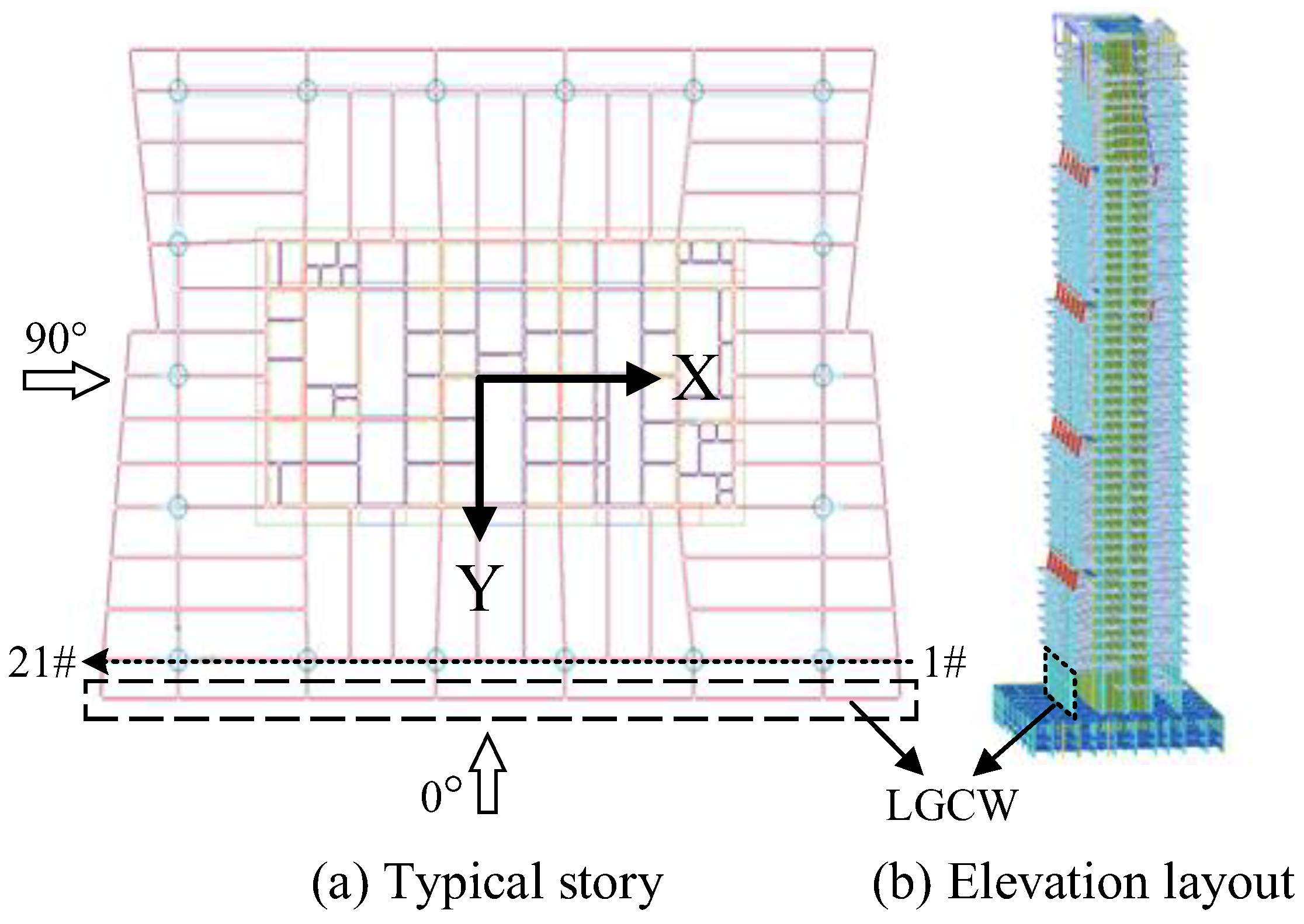
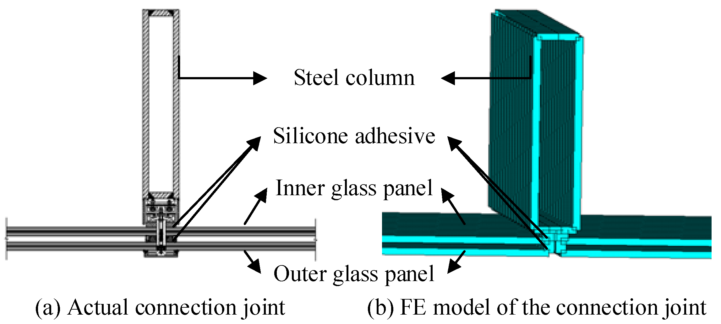
3.1. FE Model of the LGCW with the High-Rise Building

Based on the FE model of the independent LGCW in Section 2.1, the FE model of the LGCW with the high-rise building is established, as shown in Figure 8a. To simplify the actual complex connection between the LGCW and the high-rise building, coupling constraints are utilized to connect the columns of the LGCW with the floor slabs of the high-rise building, where the displacement degrees of X, Y, and Z are coupled. It should be mentioned that the silicone adhesive between the LGCW and the crossbeams helps the LGCW to easily adapt to the deformation caused by the building, while crossbeams and columns are connected by joint nodes and the latter is coupled to floor slabs. The interaction effects between the high-rise building and the LGCW are transmitted through the coupling constraints. Modal analysis is carried out for the overall model and the former nine vibration modes are shown in Figure 8b–j. The former two modes (b–c) are translational and the third mode (d) is torsional. The former six modes are dominated by the vibration of the high-rise building, and the LGCW has almost no vibration. In the eighth and ninth modes, the high-rise building and the LGCW vibrate together.

3.2. Wind Resistance Performance of the LGCW Attached to the High-Rise Building

According to Section 2.2, the most unfavorable wind direction of the independent LGCW is 0°. Meanwhile, the minimum wind-induced responses of the LGCW appear at the wind direction of 90°, the cross-wind vibration of the high-rise building is obvious, and the deformation of the high-rise building may produce a larger increase of the responses of the LGCW at this wind direction than at other wind directions. Thus, the wind-induced responses of the LGCW with the high-rise building subjected to wind loads at 0° and 90° are analyzed, including three cases: (a) only wind loads on the LGCW, and these wind loads are the same as those in Section 2.1; (b) only wind loads on the high-rise building, where the equivalent static wind loads (ESWLs) determined by wind tunnel tests are acting on the high-rise building, including down-wind and cross-wind ESWLs; (c) wind loads on both the LGCW and the high-rise building, where the wind loads from the former two cases are used.
The out-of-plane displacements and von Mises stresses of the LGCW at 0° and 90° are shown in Figure 9 and Figure 10, respectively. In case (a), the distributions of the out-of-plane displacements and von Mises stresses of the LGCW with the high-rise building are similar to those without the high-rise building, and the responses reach the maximum at the center of each glass panel and gradually decrease away from the center towards the glass panel edges. In case (b), the distributions of the out-of-plane displacements and von Mises stresses of the LGCW are significantly different from those of case (a). Since the column top of the LGCW is connected to the second floor slab of the high-rise building, and the column bottom is connected to the first floor slab, the deformation of the high-rise building transmits firstly to the top edge of the LGCW, which makes the out-of-plane displacements and von Mises stresses of the LGCW decrease away from the top edge towards the bottom edge of the glass panels. It is worth to mention that the stress magnitudes of the glass panels are small, less than 1 MPa, and this may be attributed to the elastic connections between the LGCW and the high-rise building, which release the in-plane and out-of-plane constraints on the LGCW, and decrease the influence of the high-rise building on the LGCW. In case (c), the magnitudes of the out-of-plane displacements of the LGCW increase significantly compared to those of case (a), while the von Mises stresses seldomly change. The reason is that the additional stresses of the LGCW caused by the deformation of the high-rise building in case (b) are small and relatively large values appear on the top edge and bottom edge of the glass panels, but the von Mises stresses of the LGCW in case (a) reach their maximum at the center of each glass panel, and the superposition of the two kinds of stresses changes the stress distribution of the LGCW slightly. The response distribution and peak responses of the whole LGCW at 90° are similar to those at 0°, and the additional out-of-plane displacements of the LGCW induced by the high-rise building are large, while the additional von Mises stresses are small.
Figure 11 displays the peak response of each glass panel at 0° and 90°, and the peak response of each glass panel appears at different locations of each glass panel. In case (b), the peak additional out-of-plane displacements and von Mises stresses induced by the high-rise building of each glass panel are almost the same, and the magnitudes of the peak out-of-plane displacements at 0° are larger than those at 90°. In case (c), the peak out-of-plane displacements of glass panels increase significantly in comparison to those of case (a), and the peak out-of-plane displacement of the whole LGCW at 0° (the peak out-of-plane displacement of glass panel #18) increases from 11.1 mm to 15.6 mm, i.e., by 40.5%, while the peak out-of-plane displacement of the whole LGCW at 90° (the peak out-of-plane displacement of glass panel #3) increases from 4.5 mm to 7.1 mm, i.e., by 57.4%. Since the peak additional von Mises stresses of the whole LGCW at 0° and 90° in case (b) are very small, the peak von Mises stresses of the whole LGCW changes a little in comparison to case (a).
Figure 12 displays the responses at the location of each glass panel where the peak additional response appears at 0° and 90° in case (b), which is shown in Figure 11. It can be found that the out-of-plane displacements of case (a) are very small, but after the superposition of the additional out-of-plane displacements induced by the high-rise building, the peak out-of-plane displacement of the whole LGCW in case (c) at 0° (the out-of-plane displacement of glass panel #18) increases from 1.7 mm to 7.6 mm, and the peak out-of-plane displacement of the whole LGCW in case (c) at 90° (the out-of-plane displacement of glass panel #4) increases from 0.7 mm to 3.9 mm, but the von Mises stresses are still small after the superposition of the additional stresses.
The responses of the LGCW induced by the wind loads on the LGCW reach peak values at the center of each glass panel, while the peak values of the additional response of the LGCW caused by the deformation of the high-rise building appear at the top edge of each glass panel. The deformation of the high-rise building significantly influences the out-of-plane displacements of the LGCW, especially in the top area of each glass panel, but slightly influences the stresses of the LGCW. Based on the above, the effects of the deformation of the high-rise building on the out-of-plane displacements of the LGCW should be considered, especially the responses at the top edge of the LGCW.

4. Parameter Sensitivity Analysis of the Effects of the High-Rise Building on the LGCW

The lateral stiffness of the high-rise building and the connection stiffness between the LGCW and the high-rise building are two parameters that affect the interaction between the high-rise building and the LGCW. This section conducts the parameter sensitivity analysis to investigate their influences on the responses of the LGCW.

4.1. Wind Loads on the High-Rise Building

The gust loading factor used in the ESWL mainly depends on structural characteristics. According to the calculation method of ESWLs utilized by GB50009-2012 [26], the along-wind and cross-wind ESWLs of the high-rise buildings are determined by Equations (4) and (5), respectively:
W D K = β z μ s μ z w 0
and
W L K = g w 0 μ z C L 1 + R L 2
where μ s is the shape coefficient of wind loads. μ z is the height coefficient of wind pressures at the reference height. w 0 is the basic wind pressure with a 50-year return period. g is the peak factor. β z is the response vibration factor for the along-wind response and is closely related to the natural frequency of the first mode with the along-wind vibration. R L is the cross-wind resonance factor and is closely related to the natural frequency of the first mode with the cross-wind vibration. C L is the cross-wind force coefficient.
During the investigation of the effects of the stiffness of the high-rise building on the response of the LGCW, this study assumes that the geometric shape of the high-rise building remains unchanged. Thus, all parameters in Equations (4) and (5), except the response vibration factor β z and the cross-wind resonance factor R L , remain unchanged. When the natural frequency changes due to the change in the structural stiffness, the ESWLs of the high-rise building with frequency f1 are calculated as follows:
W D K = β z 1 β z 0 W D K T
and
W L K = 1 + R L 1 2 1 + R L 0 2 W L K T
where β z 1 and β z 0 are the response vibration factors of the high-rise building with frequency f1 and of the high-rise building with frequency f0 shown in Figure 8, respectively. R L 1 and R L 0 are the cross-wind resonance factors of the high-rise building with frequency f1 and of the high-rise building with frequency f0, respectively. W D K T and W L E T are the along-wind and cross-wind ESWLs of the standard building, respectively, and are obtained from wind-tunnel tests and dynamic analysis.

4.2. Effects of the Lateral Stiffness of the High-Rise Building on the LGCW

To study the effects of the lateral stiffness of the high-rise building on the LGCW, the fundamental frequency is changed by changing the concrete elastic modulus. Similar to Section 3, three cases (a), (b), and (c) subjected to the wind loads calculated in Section 4.1 at the wind direction of 0° are analyzed for each high-rise building.
Table 4 shows the peak out-of-plane displacements and the peak von Mises stresses of the whole LGCW with the high-rise building with different fundamental frequencies for each case. It can be seen from Table 4 that with the increase in the fundamental frequency, the peak responses of the whole LGCW in case (a) change a little, and the peak out-of-plane displacements of the whole LGCW decrease in case (b). When the fundamental frequency equals 0.085 Hz, the peak out-of-plane displacement and the peak von Mises stress of the whole LGCW are 29 mm and 0.78 MPa, respectively, which are 4.1 and 6.0 times those of the original fundamental frequency 0.162 Hz. When the fundamental frequency equals 0.452 Hz, the peak out-of-plane displacement and the peak von Mises stress of the whole LGCW are 0.8 mm and 0.02 MPa, respectively, which are 0.1 times and 0.15 times those of 0.162 Hz. In case (c), the peak out-of-plane displacement decreases gradually with the increase of the fundamental frequency of the high-rise building. The peak out-of-plane displacements at the frequency of 0.085 Hz and 0.452 Hz are 2.12 times and 0.74 times those of 0.162 Hz, respectively. The peak out-of-plane displacements of three fundamental frequencies for case (c) are 2.9, 1.41, and 1.04 times those for case (a), while the peak von Mises stresses seldomly change.
The changes of the fundamental frequency produce great effects on the additional responses of the LGCW in case (b). The smaller the fundamental frequency of the high-rise building is, the greater the deformation of the high-rise building is and the greater the additional responses of the LGCW are.

4.3. Effects of the Connection Stiffness on the LGCW

The LGCW is connected to the top and bottom crossbeams with silicone adhesive, and the crossbeams are connected to the high-rise building. The bending stiffness of the crossbeams varies with the cross section of the crossbeam, which will affect the load transformation and deformation of the high-rise building and the LGCW. The silicone adhesive between the crossbeam and the LGCW is elastic. When the silicone adhesive is aged, its elastic modulus changes and will affect the connection stiffness between the high-rise building and the LGCW. Thus, this section analyzes the influences of the varying crossbeam sections and the varying stiffness of the silicone adhesive on the peak responses of the whole LGCW for each case.
Table 5 displays the peak responses of the whole LGCW for different crossbeam sections and elastic modulus of silicone adhesive. It can be found that the peak out-of-plane displacements of the whole LGCW in case (a) decrease with the increase of the crossbeam section. When the crossbeam width equals 0.04 m and 1 m, the peak out-of-plane displacements are 1.12 and 0.89 times those of the original crossbeam width 0.2 m, respectively. In case (b), the peak von Mises stresses of the whole LGCW decrease a little with the increase of the crossbeam section. When the crossbeam width equals 0.04 m and 1 m, the peak von Mises stresses are 1.11 and 0.98 times those of 0.2 m, respectively. In case (c), the peak out-of-plane displacements of the whole LGCW also decrease with the increase of the crossbeam section. When the crossbeam width equals 0.04 m and 1 m, the peak out-of-plane displacements in case (c) are 1.09 and 0.92 times those of 0.2 m, respectively. The peak out-of-plane displacements of the whole LGCW in case (c) are 1.37, 1.41, and 1.47 times those of case (a), and the peak von Mises stresses seldomly change.
With the increase of the elastic modulus of the silicone adhesive, the peak responses of the whole LGCW decrease in case (a). In case (b), the peak out-of-plane displacements of the whole LGCW change a little while the peak von Mises stresses increase a lot with the increase of the elastic modulus of the silicone adhesive. In case (c), the peak out-of-plane displacements of the whole LGCW decrease with the increase of the elastic modulus of the silicone adhesive. The peak out-of-plane displacements of the whole LGCW in case (c) are 1.31, 1.41, 1.46 times those of case (a), while the peak von Mises stresses seldomly change.
It is worth noting that the crossbeam width and the elastic modulus of the silicone adhesive are related to the connection stiffness which influences the wind-induced response of the LGCW. A smaller stiffness of the crossbeam and the silicone adhesive means a smaller connection stiffness between the LGCW and the high-rise building, and smaller out-of-plane constraints of the high-rise building on the LGCW. A smaller connection stiffness leads to greater responses of the LGCW induced by the wind loads on the LGCW itself, and greater total responses after considering the effects of the deformation of the high-rise building on the LGCW. Since the additional von Mises stresses caused by the high-rise building are small, the effects of the high-rise building on the total von Mises stresses of the LGCW are also small.

5. Conclusions

This study constructed FE models of the independent LGCW and of the LGCW with the high-rise building to investigate the wind resistance performance of the LGCW considering the deformation of the high-rise building. Then, the parameter sensitivity analysis of wind effects on the LGCW was conducted varying the lateral stiffness of the high-rise building and the connection stiffness between the high-rise building and the LGCW. The main conclusions are as follows:
(1) The wind-induced out-of-plane displacements and von Mises stresses of the LGCW decrease away from the center towards the glass panel edges. The additional out-of-plane displacements and von Mises stresses of the LGCW caused by the deformation of the high-rise building decrease away from the glass panel’s top and bottom edges towards the center of the LGCW.
(2) Since elastic connections are used between the LGCW and the high-rise building, the effects of the deformation of the high-rise building on the out-of-plane displacements of the LGCW are considerable, while those on the von Mises stresses of the LGCW are slight. When the deformation of the high-rise building is included, the peak out-of-plane displacement of the whole LGCW is increased by 40.5%.
(3) The lateral stiffness of the high-rise building and the connection stiffness between the LGCW and the high-rise building have significant effects on the displacements of the LGCW. The smaller the lateral stiffness of the high-rise building is, the greater the additional responses caused by the deformation of the high-rise building in the LGCW are. The smaller the connection stiffness is, the greater the responses of the independent LGCW are, but the additional responses induced by the deformation of the high-rise building on the LGCW are not significant.

Author Contributions

Conceptualization, B.C., L.J. and H.Y. (Hongliang Yu); methodology, L.J.; software, L.J. and H.Y. (Handi Yang); validation, L.Z., L.J. and B.C.; investigation, L.J.; writing—original draft preparation, L.J.; writing—review and editing, B.C. and L.Z.; supervision, B.C.; project administration, W.Y. and H.Y. (Handi Yang); funding acquisition, H.Y. (Hongliang Yu). All authors have read and agreed to the published version of the manuscript.

Funding

The research is funded by Zhejiang Jiangnan Project Management Co., Ltd. (Grant number: H20200924).

Data Availability Statement

Data will be made available on request.

Conflicts of Interest

The authors declare no conflict of interest.

References

  1. Lu, W.; Wang, Y.; Chen, H.D.; Jiang, L.; Duan, Q.L.; Li, M.; Wang, Q.S.; Sun, J.H. Investigation of the thermal response and breakage mechanism of point-supported glass facade under wind load. Constr. Build. Mater. 2018, 186, 635–643. [Google Scholar] [CrossRef]
  2. China Architecture and Building Press. Technical Code for Application of Architectural Glass; JGJ/113-2015; China Architecture and Building Press: Beijing, China, 2015. [Google Scholar]
  3. Huang, B.F.; Chen, S.M.; Lu, W.S.; Mosalam, K.M. Seismic demand and experimental evaluation of the nonstructural building curtain wall: A review. Soil Dyn. Earthq. Eng. 2017, 100, 16–33. [Google Scholar] [CrossRef]
  4. Tsai, C.R.; Stewart, R.A. Stress analysis of large deflection of glass plates by the finite-element method. J. Am. Ceram. Soc. 1976, 59, 445–448. [Google Scholar] [CrossRef]
  5. Gavanski, E.; Kopp, G.A. Glass breakage tests under fluctuating wind loads. J. Archit. Eng. 2011, 17, 34–41. [Google Scholar] [CrossRef]
  6. Shetty, M.S.; Dharani, L.R.; Stutts, D.S. Analysis of laminated architectural glazing subjected to wind load and windborne debris impact. ISRN Civil. Eng. 2012, 2012, 949070. [Google Scholar] [CrossRef] [Green Version]
  7. Quaglini, V.; Cattaneo, S.; Pettorruso, C.; Biolzi, L. Cold bending of vertical glass plates: Wind loads and geometrical instabilities. Eng. Struct. 2020, 220, 110983. [Google Scholar] [CrossRef]
  8. Bedon, C.; Zhang, X.H.; Santos, F.; Honfi, D.; Kozłowski, M.; Arrigoni, M.; Figuli, L.; Lange, D. Performance of structural glass facades under extreme loads—Design methods, existing research, current issues and trends. Constr. Build. Mater. 2018, 163, 921–937. [Google Scholar] [CrossRef]
  9. Nečasová, B.; Liška, P.; Šimáčková, M.; Šlanhof, J. Test of adhesion and cohesion of silicone sealants on facade cladding materials within extreme weather conditions. Adv. Mater. Res. 2014, 1041, 23–26. [Google Scholar] [CrossRef]
  10. Van Lancker, B.; Dispersyn, J.; De Corte, W.; Belis, J. Durability of adhesive glass-metal connections for structural applications. Eng. Struct. 2016, 126, 237–251. [Google Scholar] [CrossRef]
  11. Belis, J.; Bedon, C.; Louter, C.; Amadio, C.; Van Impe, R. Experimental and analytical assessment of lateral torsional buckling of laminated glass beams. Eng. Struct. 2013, 51, 295–305. [Google Scholar] [CrossRef]
  12. Huveners, E.M.P. Circumferentially adhesive bonded glass panes for bracing steel frames in facades; Eindhoven University of Technology: Eindhoven, The Netherlands, 2009. [Google Scholar]
  13. Antolinc, D.; Rajčić, V.; Žarnić, R. Analysis of hysteretic response of glass infilled wooden frames. J. Civ. Eng. Manag. 2014, 20, 600–608. [Google Scholar] [CrossRef]
  14. Yuan, Y.; Zhou, Y.F.; Wang, L.X.; Wu, Z.R.; Liu, W.B.; Chen, J.B. Coupled deformation behavior analysis for the glass panel in unitized hidden-frame supported glass curtain wall system. Eng. Struct. 2021, 244, 112782. [Google Scholar] [CrossRef]
  15. Gonçalves, M.D. Patenaude-Trempe and Robert Jutras, Air-Ins. Evaluating the field performance of windows and curtain walls of large buildings. In Proceedings of the BEST2 Conference—Building Enclosure Science & Technology, Portland, OR, USA, 12–14 April 2010. [Google Scholar]
  16. Ilter, E.; Tavil, A.; Celik, O.C. Full-scale performance testing and evaluation of unitized curtain walls. J. Fac. Des. Eng. 2015, 3, 39–47. [Google Scholar] [CrossRef] [Green Version]
  17. Wai So, A.K.; Chan, S.L. Stability and strength analysis of glass wall systems stiffened by glass fins. Finite Elem. Anal. Des. 1996, 23, 57–75. [Google Scholar] [CrossRef]
  18. Di, P.; Yu, C.L. Safety analysis of point supported glass curtain wall panels. In Proceedings of the 4th International Conference on Sustainable Energy and Environmental Engineering, Shenzhen, China, 30–31 December 2016; pp. 1140–1144. [Google Scholar] [CrossRef] [Green Version]
  19. Yu, Y.; Liu, T.; Zhang, Q.L.; Yang, B. Wind-induced response of an l-shaped cable support glass curtain wall. Shock. Vib. 2017, 2017, 4163045. [Google Scholar] [CrossRef] [Green Version]
  20. Zasso, A.; Perotti, F.; Rosa, L.; Schito, P.; Pomaranzi, G.; Daniotti, N. Wind Pressure Distribution on a Porous Double Skin Façade System. In Proceedings of the XV Conference of the Italian Association for Wind Engineering, Naples, Italy, 9–12 September 2018; Springer: Berlin/Heidelberg, Germany, 2019; pp. 730–741. [Google Scholar]
  21. Lu, W.S.; Huang, B.F.; Chen, S.M.; Mosalam, K.M. Shaking table test method of building curtain walls using floor capacity demand diagrams. Bull. Earthq. Eng. 2016, 15, 3185–3205. [Google Scholar] [CrossRef]
  22. Lu, W.S.; Huang, B.F.; Mosalam, K.M.; Chen, S.M. Experimental evaluation of a glass curtain wall of a tall building. Earthq. Eng. Struct. Dyn. 2016, 45, 1185–1205. [Google Scholar] [CrossRef]
  23. Pomaranzi, G.; Daniotti, N.; Schito, P.; Rosa, L.; Zasso, A. Experimental assessment of the effects of a porous double skin façade system on cladding loads. J. Wind. Eng. Ind. Aerodyn. 2020, 196, 104019. [Google Scholar] [CrossRef]
  24. Ren, C.C.; Li, J.H.; Tang, Y.; Liu, J.J.; Yan, Y.L.; Hao, W.; Sun, C. Performance study of main structure and glass curtain wall of high-rise building under combined action of wind and earthquake. Eng. Mech. 2022, 39, 58–69. (In Chinese) [Google Scholar] [CrossRef]
  25. Ren, C.C.; Liu, J.J.; Li, J.H.; Tang, Y.; Yan, Y.L.; Wang, C. Study on structural damage and falling of glass curtain wall of super high-rise building under coupling action of wind and earthquake. J. Build. Struct. 2022, 43, 129–140. (In Chinese) [Google Scholar] [CrossRef]
  26. China Architecture and Building Press. Load Code for the Design of Building Structures; GB 50009; China Architecture and Building Press: Beijing, China, 2012. [Google Scholar]
Figure 1. The structural layout and wind direction.
Buildings 13 00636 g001
Figure 2. The connection joint of the LGCW.
Buildings 13 00636 g002
Figure 3. The FE model of the LGCW.
Buildings 13 00636 g003
Figure 4. Wind load distribution of the hollow double-layer glass panel.
Buildings 13 00636 g004
Figure 5. Pressure measurements of the LGCW.
Buildings 13 00636 g005
Figure 6. Response distribution of the independent LGCW at 0° and 90°.
Buildings 13 00636 g006
Figure 7. Peak responses of inner glass panels.
Buildings 13 00636 g007
Figure 8. FE model and former nine modes of the LGCW with the high-rise building.
Buildings 13 00636 g008
Figure 9. Response distribution of the LGCW at 0°.
Buildings 13 00636 g009
Figure 10. Response distribution of the LGCW at 90°.
Buildings 13 00636 g010
Figure 11. Peak responses of inner glass panels.
Buildings 13 00636 g011aBuildings 13 00636 g011b
Figure 12. Responses at the location of each glass panel with peak additional response.
Buildings 13 00636 g012
Table 1. Material parameters.
MaterialElastic Modulus (N/mm2)Poisson’s RatioMass Density (kN/m3)
Glass72,0000.225.6
Silicone adhesive20.49915
Steel200,0000.378
Table 2. μ s l of the LGCW.
Wind DirectionNumber of Glass Panels
#1#2–3#4–5#6–8#9–13#14–16#17–18#19–20#21
−0.62−0.210.320.740.91.051.0510.98
90°−0.49−0.46−0.34−0.34−0.33−0.29−0.19−0.1−0.24
180°−0.44−0.42−0.41−0.42−0.42−0.41−0.41−0.41−0.41
270°−0.5−0.48−0.44−0.35−0.41−0.47−0.45−0.44−0.52
Table 3. Statistical response values of glass panels at 0°.
TypeOuterInnerOuter/Inner
Out-of-plane displacements (mm)Peak12.611.41.1
Mean4.383.921.1
Von Mises stresses (MPa)Peak6.475.781.1
Mean2.942.641.1
Table 4. Peak responses of the LGCW for different fundamental frequencies.
Fundamental FrequencyPeak Out-of-Plane Displacements (mm)Peak Von Mises Stresses (MPa)
Case (a)Case (b)Case (c)Case (a)Case (b)Case (c)
0.08511.42933.15.790.785.81
0.16211.1715.65.790.135.79
0.45211.10.811.55.790.025.79
Table 5. Peak responses of the LGCW.
VariablesValuesPeak Out-of-Plane Displacements (mm)Peak Von Mises Stresses (MPa)
Case (a)Case (b)Case (c)Case (a)Case (b)Case (c)
Crossbeam width (m)0.0412.47175.80.1495.8
0.211.1715.65.790.1345.79
19.8714.45.790.1315.79
Elastic modulus of silicone adhesive (N/mm2)2 × 10515719.75.90.085.9
2 × 10611.1715.65.790.1345.79
2 × 1079.7714.25.230.555.22
Disclaimer/Publisher’s Note: The statements, opinions and data contained in all publications are solely those of the individual author(s) and contributor(s) and not of MDPI and/or the editor(s). MDPI and/or the editor(s) disclaim responsibility for any injury to people or property resulting from any ideas, methods, instructions or products referred to in the content.

