1. Introduction
The UN’s efforts at several climate change conferences (e.g., COP26 conference as an example) have promoted mitigation strategies to reduce the effect of greenhouse gas emissions and, subsequently, global warming. The utilization of renewable energy sources, such as solar energy, is considered an attractive solution to meet these mandates, which will subsequently reduce greenhouse gas emissions by 2030 [
1]. According to Praveenkuma et al. [
2,
3], the mode of energy production is an important contributor to climate change, accounting for more than 60% of global greenhouse gas emissions. Indeed, the long-term consequences of greenhouse gas emissions and rising fossil fuel prices have prompted an increase in global interest and investment in renewable energy sources. Solar energy is considered an attractive option because it is renewable, abundant, ecological, and green. This energy source is ideal for the energy transition and, at the same time, beneficial to the environment.
Solar can potentially be utilized to supply heating and electrical energy for domestic and public use. In particular, the use of solar for domestic hot water has promising perspectives. According to the Ecological Transition Agency (ADEME), the domestic hot water (DHW) of a French household in 2012 represented 12.1% of the average energy consumption compared to 61.3% for heating and 7% for cooking [
4]. To determine the energy consumption of the electric water heater storage tank, several factors must be taken into account: the capacity of the hot water tank and the family characteristics (i.e., number, behavior, hot water consumption patterns, etc.). Regardless of the tank capacities (i.e., 50 L, 150 L, or 200 L), the hot water tank consumes a relatively high amount of electricity. A few daily actions may be necessary to reduce hot water consumption, but the choice of the type of water heater impacts this consumption and, therefore, the energy consumption. The electric storage heater with the joule effect is sometimes the most widely used electric DHW production system [
5]. It is the easiest and most straightforward approach to producing hot water in the housing sector. It consists of a corrosion-protected tank, an electrical resistance, and a thermostat to regulate the water temperature inside the tank. The content is spontaneously replaced as the produced hot water is consumed. According to a recent review study, water heating can be accomplished using electricity, gas, or renewable energy in different countries and regions, including Australia, Brazil, Canada, China, European Union, India, South Korea, and the United States [
6]. Several essential criteria may be used to select among these types, including economic, ecological, and energy performance [
7,
8,
9,
10,
11].
Hot water is widely used for domestic purposes (e.g., DHW) and space heating. In South Africa, the water heating process requires a large amount of energy, estimated at 40% of the total energy, mainly using electrical energy [
12]. According to Catherine et al. [
13], a typical middle-class residential building can consume, on average, about 11,797 kWh/year, out of which 4259 kWh/year (~36.1%) is used for water heating. In the United States, the heating energy for DHW at the urban scale represents 17% [
14]. Nearly 40% of buildings use electricity for water heating. This fraction differs significantly from state to state, with more than 80% of facilities in some states and less than 15% of others using electric storage tank water heaters.
The intensive use of electricity for heating has motivated some researchers [
15] to propose solutions for energy savings. One effective solution was to control the electricity supply of water heaters during peak hours in residential buildings [
16]. The thermal efficiency of storage-type electric water heaters is affected by the control mechanism. In 2005, according to Jiang and Yang [
17,
18], the number of water heating units in China was 72.7 per 100 urban households. Gas, electric, and solar water heaters accounted for 57.4%, 31.3%, and 11.3%, respectively. Electric water heaters have a significant share of the Chinese market due to low installation costs and product profitability, but it was also noted that their design lacks innovation. The main topics of existing studies focused on the improvement of energy efficiency, availability, and quality of product installation services [
19]. In contrast to the other studies on electric water heaters, which have shown a declining trend, there has been a significant increase in studies on air and solar water heaters between 1998 and 2014 [
19]. Tan et al. [
20] have proposed a practical method to improve the storage type electric water heater by integrating an intelligent control system driven by a single-chip microcomputer for safe operations. Dong [
21] has conducted a correlation analysis on factors affecting user satisfaction with electric water heaters.
On the other hand, the most important function of the storage-type electric water heater is to heat the water using electrical energy and store it for later use. Electrical energy is supplied to the electrical resistive elements inside the storage-type water tank. Current flows through the elements to create heat, which generates thermal energy that will then be exchanged with the surrounding water. Unfortunately, this heating process requires significant energy that has become unaffordable in recent years. Therefore, alternative heating technologies are indisputable and must be utilized to reduce overall operating costs. As a result of these financial and technical challenges, renewable energy must be used to reduce energy consumption and the associated energy cost in the residential sector. Solar or hybrid water heaters can be an effective solution to overcome the expensive energy cost. According to the literature [
22,
23,
24,
25], the choice generally focuses on the forced circulation solar water heater due to its considerable strength compared to the thermosiphon solar water heater. In addition, the storage water tank can be positioned anywhere without introducing further system complexity. This type is adaptable and suitable for all configurations. The heat-transfer fluid circulating in its circuit will be propelled by a variable-speed drive pump to ensure optimal heat exchange.
Despite the advantages of the above classical systems, solar water heating systems are considered efficient and economical for producing hot water. In Romania, for example, solar water heating has shown a substantial reduction in energy consumption by up to 71%. Consequently, a considerable rate of greenhouse gas emissions has been reduced, estimated at 18.5 tons of CO
2 over the lifetime of the system, with an updated payback period of 6.8 to 8.6 years. The financial benefits of using solar water heating are tangible, but they may not be immediately visible or quick to justify the cost of installation, which is why government subsidies and incentives are essential [
26]. In one study, the analysis of the efficiency of a solar water heating system has shown that the most suitable period to support a well-functioning solar water heating system is from April to September, during which the share of DHW production is close to 78%. This has resulted in a reduction of 6% in gas consumption (i.e., 2000 m
3 of gas) throughout the year for a multi-family building. The annual financial savings, including running costs, totaled 4541.07 PLN (Polish Zloty). Considering the increase in gas prices, which was 8%, and the annual operating costs, which were above 5%, it was found that the return on investment compared to the conventional solution was less than thirteen and a half years [
27]. In Oman, the integration of water heating systems has led to a good investment project for both homeowners and the government. The return on investment can be between 7 and 10 years if half of the capital cost is provided by the government [
28]. A study in India indicated that a government incentive of at least 50% is needed to make the solar water heating system economically feasible [
29]. In the suburbs of Bangkok, Thailand, it has been shown that solar water heating can supply at least 88% of the hot water demand for typical housing, mainly used for bathing [
30]. The study indicated that investing in solar water heating was more economically attractive than investing in envelope or lighting systems. Šahić et al. [
31] have demonstrated that significant electrical energy savings (~30%) can be achieved by installing a solar system for sanitary water heating.
In Algeria, electricity is generated using open-cycle gas turbines, which is considered an expensive method for electrical generation. The government subsidizes electricity, which leads to excessive energy use. More than 72% of the produced energy is consumed in the southern region of Algeria, while the rest is consumed in the coastal and highland areas. For typical housing in Algeria, water heating consumes between 20% and 30%, mainly using electricity [
32]. One useful approach is to reduce electrical energy use for water heating. Due to the variability and the intermittent nature of solar radiation, thermal energy storage using phase change materials (PCMs) has shown the potential to elongate the use of solar energy and maintain setpoint water temperatures for a more extended period. In addition, in the last years, electric storage water heaters have been subjected to technical challenges such as low heating rates and inconsistent temperature control of the stored water. These operational problems have resulted in insufficient hot water production and irregular hot water supply, which could create inconvenience to users.
The latent energy storage with PCM balls provides an excellent solution for inadequate energy production and consumption [
33]. Other studies [
34,
35,
36] have examined the addition of nanoparticles to PCM. In the best case, it was found that this composition has reduced the melting time by 43% and saved 147% more latent energy compared to pure paraffin. Under other conditions, the optimal diameter of the PCM balls should be between 90 and 60 mm for the best inlet flow rate of 2.196 m
3/h [
33]. The presence of PCM in the water tank resulted in the appearance of two areas in which the water temperature remains constant due to the melting and solidification phenomenon [
37]. However, some results showed that the total PCM melting in the tank, which contains paraffin integrated directly in its lateral part, lasts almost twice as long as in the tank with a PCM centered on the axis [
38].
This contribution focuses first on the method of incorporating PCM, which has been adapted and is compatible with the proposed shape of the storage tanks. The approach was straightforward and simple to complete, but it is generally different from other existing integration methods. The second objective was to determine the influence of the specific climatic conditions in this region, which have distinct characteristics from some regions of the world. Their peculiarity is deserts, warm, dry, and located in the north of the Algerian Sahara. It is characterized by very strong solar irradiation, with sometimes a record number of hours of sunlight, as well as very low humidity, great dryness of the atmosphere, and calm, rarely violent winds. The new PCM has already been tested using a purely electrical energy source for heating the water in the storage tank, and advanced trials are showing promising results. However, their reactions to the combined heating system using solar energy and electricity as a backup remain to be understood. A comparison between the two DHW heating modes was discussed.
This article reports an experimental analysis on PCM embedded flat plate solar collector coupled with electric heater. This study proposes a design configuration for an active water heater embedded with PCM that can provide a reliable design solution. The system is hybrid which consists of a flat plate solar collector and an electric heater. In this work, the thermophysical properties of a newly proposed PCM are characterized. Then, the integration mechanism with the active water heater is illustrated. The comparison of the performance of this hybrid energy source system, which consists of a conventional flat plate collector and a PCM storage tank, based on energy consumption, has been widely discussed. The analysis was based on a single day of experimental data corresponding to only a single test. The renewal of a comparative test corresponding to the same case was based on experiments carried out on another day similar to the previous one. The only and main objective is, therefore, to greatly reduce the amount of primary energy needed for the domestic use of hot water. This conducted research was confined to the measurement of the power consumption by the entire energy systems and the average temperature in the storage tanks according to their equivalent heat loss coefficients (U-value). The stated objectives are, therefore, not concerned with determining the thermal performance of the flat-water collector or the variation of the water inlet and outlet temperatures. This important issue was already solved in many distinguished contributions [
39,
40,
41,
42,
43] and served as further contributions. In addition to the technical feasibility, the economic feasibility is also conducted for this new PCM-integrated hybrid water heater. Several parameters are determined at various thermostat setpoints, including produced hot water volume, a substantial gain in production terms, corresponding electric bills, the unit price corresponding to a produced volume at 50 °C, and the financial gain.
2. Material and Method
2.1. General Method and Basic Principles of the Operating System
The improvement of the DHW heating system compared to the old one [
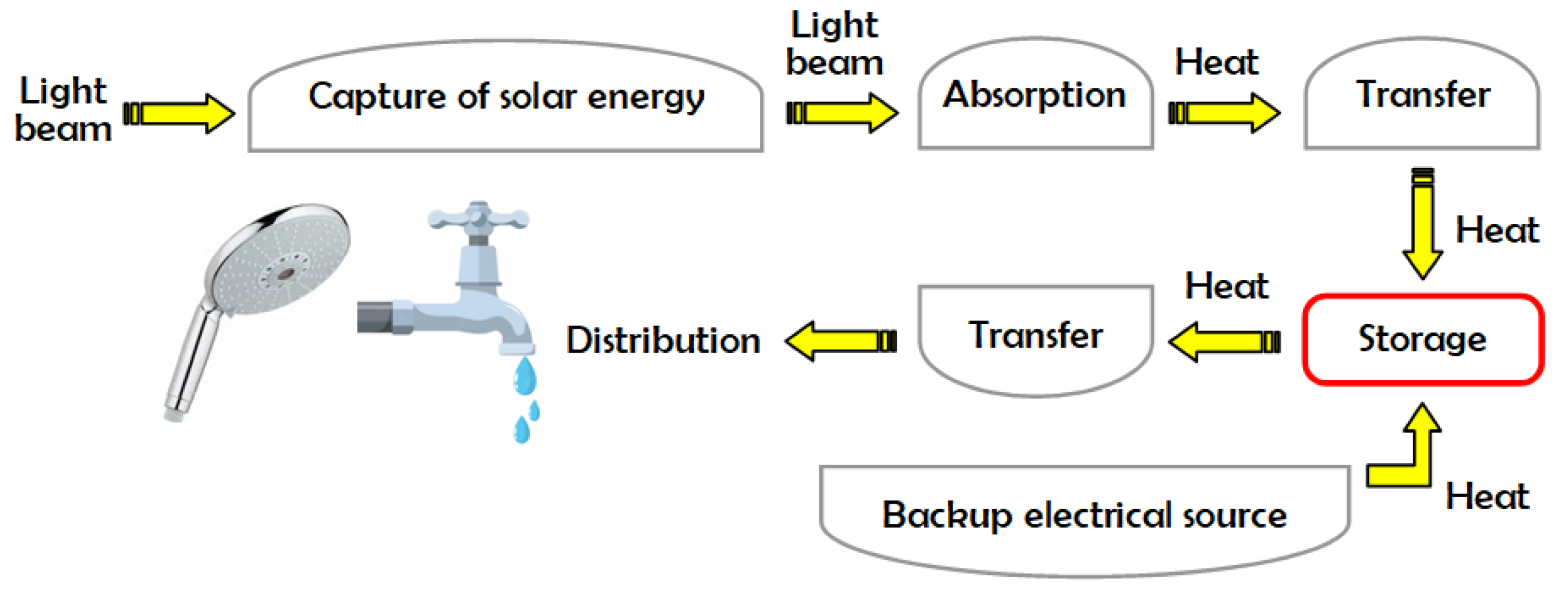
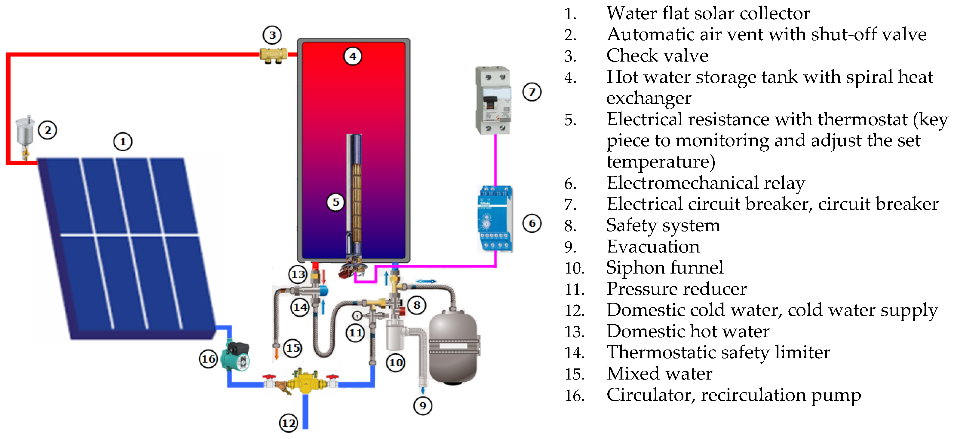
44] is therefore at the installation level and the energy sources used for the heating process. A flat water collector is fixed on a terrace about 12 m high and then connected to the two storage tanks placed on the building’s ground floor by insulated water pipes. The hydraulic circuit is designed to provide reliability and better controllability. A new hybrid (i.e., solar and electrical) water heater is proposed for integration into residential buildings, consequently reducing the energy cost of water heating, mainly for domestic use. The installation is an active solar thermal system consisting of a storage tank, pipes, and pumps. Components, processes, and effects that are part of the system are broken down into sub-systems. The interactions between these components, which are in response to climatic variations and energy requirements, determine the amount of useful energy that the system will deliver. For example, the specific characteristics related to the sensor cannot be used directly to determine the produced energy since this depends on the operating sensor temperature, which in turn depends on the storage temperature. Functionally, however, the active solar system can be represented as shown in
Figure 1.
Typically, a DHW system has a single tank, but for the purposes of this study, an additional tank was added due to its specific requirements. Both tanks are filled with cold water from the source, and the hot water pipe from the water sensor splits into two directions, allowing for simultaneous and parallel filling of the tanks. Hot water is extracted from the bottom of each tank in the open air.
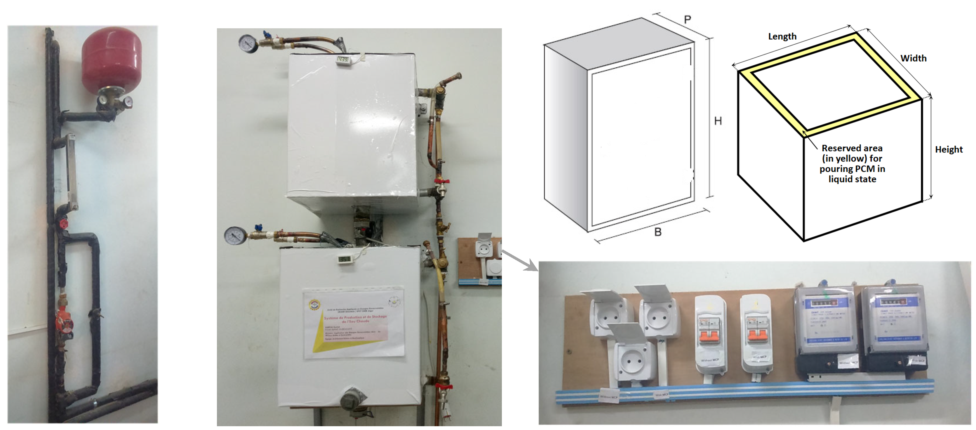
Figure 2 provides a general view of the storage system, including the arrangement of the designed tanks. The storage tank is connected to an electricity network using two precise digital meters. The power supply circuit includes a power-on device in off-peak hours protected by a modular circuit breaker. The tank’s auxiliary heating element is represented by the auxiliary electric resistance, which is of type “B2-10, 20 A, 230 V” and has an accurate power of 800 watts. The two tanks are located so that the incoming water is uniformly distributed to both tanks.
An immersed coil heat exchanger will be used inside the storage tank to warm the water that is inside of it. The thermal energy is transferred from the hot water source—a solar water heater or traditional grid electricity—to the colder water in the same storage tank through a spiraling, cylindrical device. It is made of copper, which is excellently resistant to corrosive substances and can be cold-rolled and compacted due to its design and shape. The fact that it has a maximum heat exchange coefficient and a relatively high efficiency is more significant than anything else. During the cycle of the heat transfer fluid in the coil, the heat exchanger will warm the water that has accumulated in the storage tank. The working fluid will receive direct heat transfer from this heat-transfer fluid (in this case, hot water) flowing from the solar water heater (accumulated water in the tank). Yet, due to the heat effect, the phase-change material will transform from a solid to a liquid (fusion), i.e., it will absorb the heat from the hot water that has built up in the tank as a result of the latent storage phenomena. The idea is to use the latent heat of the PCM, which will first be produced by the temperature rise of the collected water brought on by the heat exchanger’s energy source. Additionally, the PCM coming into indirect contact with the water that has accumulated in the storage tank (through a thin conductive sheet). Following the drop in temperature of the collected water, the energy lost due to the phase change during the fusion will then be recovered during the solidification phase. By doing this, the water will be kept at its highest possible temperature.
The operating conditions for both tanks are almost the same. The maximum difference in temperatures between the tanks was 0.4 °C. Two pressure gauges with an accuracy of 0.01 bar were also installed with shut-off valves to control the water flow. A cold-water inlet and hot-water outlet pipes ensure the hydraulic storage connection. A pressure reducer to the water heater is added for safety purposes.
A glazed flat plate collector of acceptable optical quality (transparent or absorbent materials) has been set up. It is a water collector with separate elements, i.e., the pure water coming out of the flat collector will go directly to the tank via a water circulator for mixing with the water in this tank. The collected Sun’s energy will be transformed into heat and then transferred by forced circulation of the heat transfer fluid (water) in the pipes to the storage system via a manually controlled circulation pump. The used pipes are made of galvanized steel characterized by a low heat conduction rate and protected with thermal insulation against thermal losses and bad weather.
After the south orientation, some parameters were chosen appropriately, such as the tilt angle of the collector and the suitable experimental water flow rate (75 L per hour). The obtained water temperature and amount of produced water, both of which vary depending on the meteorological and radiometric parameters, and financial aspects were taken into account in the volume flow optimization process. We always arrived at a curve that is a little bit closer to a bell-shaped function when calculating the fluctuation of these parameters (the attained water temperature, the quantity of produced water, and the financial equivalent cost) as a function of the volume flow. In terms of mathematics, the null value of this function’s derivative provided the precise value of the volumetric flow. However, due to the changing test conditions, an interval of approximately 72 L per hour to 98 L per hour was detected. Thus, the optimal inclination β (which is, by definition, the difference between latitude and declination) was selected to allow the sensors to be positioned perpendicular to the sun’s rays. The direction towards the south is the best orientation for a solar collector in the northern hemisphere. Mathematically,
φ: Latitude is the angle between the line traced from the point of observation and the equatorial plane at the Earth’s center.
The declination angle is about as follows [
39]:
where n denotes the day of the week.
The ideal tilt angle is found to fluctuate throughout the year between 9.73° on 21 June and 55.05° on 21 December. It is therefore possible to compile the monthly average values by analyzing the calculated daily values of the ideal angles.
In this study, an average angle was recommended because of its daily and seasonal variation. For the period between November and January, the sensors should be approximately inclined between 50° and 55°, while they should be tilted between 10° and 20° in the period from May to August, and between 35° and 45° for the rest of the year. Therefore, the easiest way is to retain the annual average between all daily inclinations, which corresponds to 32° (latitude). It should be remembered that the altitude of Ghardaïa is 503 m above sea level, its latitude: 32°29′27″ North, and its Longitude: 3°40′24″ East.
The absorber plate was coated with a black chromium selective layer. More in-depth computational work is required to give an accurate instantaneous experimental identification of the collector’s efficiency. The collector efficiency is defined as the ratio of useful heat recovered from the collector water per unit of aperture area to the irradiance. It, therefore, means that the efficiency of the same collector is not a stable characteristic. It will always fluctuate according to the solar irradiance, the difference between the water temperature at the inlet and the outlet of the sensor, and according to the water’s specific heat. Its value ranges from 4195 J/(kg °C) at 10 °C to 4197 J/(kg °C) at 80 °C. Experimental results relative to the mean solar collector’s efficiency were calculated by referring to the French P50-501 standard. As a result, the value obtained was 73.81% under very favorable test conditions on a day in November. Measurements have been recorded for four hours, two hours before and after 12 True Solar Time “TST” (i.e., from 10:31 a.m. to 2:31 p.m. for a fixed flow rate of 75 L per hour, which is equal to 2.08 10−5 m3/s and almost 0.021 kg/s). Flow meter uncertainty is +/− 5%. The solar irradiance incident on the solar collector was measured using the UARER radiometric station. The solar irradiance across the whole sensor after this test period was approximately equal to 3847 Wh/m2. This energy corresponds to an average solar radiation of 961.67 W/m2 (at 51°), which varies from 853.5 W/m2 to 1015.95 W/m2 (peak at 12 TST), knowing that the water entering temperature is between 53.15 and 56.5 °C in the sensor and exits at an average temperature of 65 °C.
In most cases, solar energy cannot ensure all energy needs. To cope with unfavorable periods (winter, mid-season, long periods of bad weather), additional energy will be needed. Thus, this storage unit is equipped with an electrical backup device, as shown in
Figure 3. The developed hybrid water heater is used as a test bench in this work.
2.2. Technical Description of the Flat Plate Solar Collector
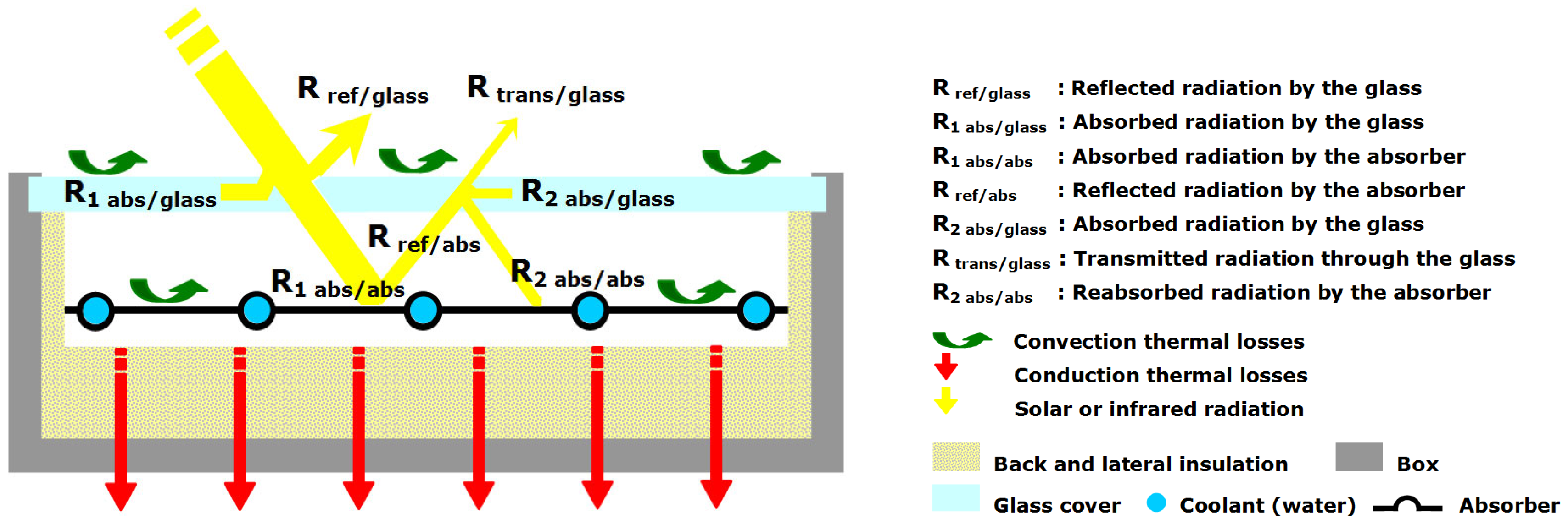
A flat plate solar collector is used to heat the water that flows in a hydraulic circuit connected to the storage tank. Solar radiations, symbolized by the yellow arrows in
Figure 4, will partially be reflected (R
ref/glass), especially if the incident angle is sharp. Despite the excellent transparency of the glass, a small part of the received energy (R
1 abs/glass) will be absorbed by the glass. The portion R
ref/abs of the received radiation by absorber R
1 abs/abs will be re-radiated or transferred to the ambient air by convection, shown as R
trans/glass in
Figure 4. Another part R
2 abs/glass will be absorbed by the glass cover, and the rest R
2 abs/abs will return to the absorber. The hybrid water heater is installed on a rooftop of an office building at the Applied Research Unit in Renewable Energies, as shown in
Figure 4.
The racking system allows several inclinations which may be used to direct the flat plate solar collector to absorb the maximum amount of solar radiation. The metal absorber is coated with dark and selective paint (black chrome) to maintain its physical (i.e., surface treatment, dilatation, etc.), thermal (i.e., conductivity, absorber-fluid connection, etc.), and hydraulic (i.e., pressure losses, fouling, purging, etc.) properties over time. The system was equipped with several protection features, including antifreeze, air oxidation, and UV rays. The transparent layer is made of tempered glass. The absorber emits the reflected solar radiation, which promotes the greenhouse phenomenon. Thermal insulation is used to minimize thermal losses to the outside environment. The physical, optical, and thermo-physical characteristics are listed in
Table 1. The system was commissioned without any noticeable water leaks.
Experimental works carried out on this MEGASUN solar water heater during the night period have shown that under the effect of generally stable climatic conditions, this prototype will achieve thermal equilibrium. At these times, the flow of water is useless, which is why the circuit will be closed under these conditions. The water temperature inside the storage tank can vary considerably depending on the degree of solar radiation [
39].
2.3. Specifications of Storage Tanks
Isothermal tanks are used for the storage of hot water in order to stabilize the water temperature. The integrated storage system is composed of the following:
Two enameled storage tanks of 80 L in parallelepiped form, equipped with well-dimensioned smooth tube heat exchangers (15 m length and 16 mm diameter) to ensure optimum performance, are used. Three precise K-type temperature sensors (with an accuracy of +/−1 °C over a wide temperature range) were immersed and centered along the symmetry axis to measure the temperature in each tank. The mean temperatures were retained for the experimental work. The main advantage of quadrangular water tanks is mainly due to their easy adaptation to the installation space (square, rectangular). They are ideal for use in garages, boiler-houses, and roof terraces. These quadrangular tanks reach maximum capacity in minimal space due to their ergonomic shape. The two storage tanks can be operated using two modes: electricity or hybrid using solar and electricity. Two main configurations of storage tanks were studied: a conventional storage tank (no PCM) and a PCM-embedded storage tank without insulation (i.e., high thermal losses). The PCM-embedded storage tank was then enhanced with thermal insulation, a design case that has low thermal losses, which represents an additional design configuration. This PCM was directly embedded in the side walls inside the storage tank in accordance with
Figure 5. It can be poured into the layer indicated by the yellow color as soon as it is in its liquid state. The three configurations are articulated in
Table 2, which provides more details about the geometric and thermal properties of the storage tanks.
Two copper electrical resistors, controlled by two encapsulated thermostats in direct contact with the stored fluid, are used. The thermostats’ main task is to cut off the electrical supply of the resistor when the required temperature is reached.
Two heat exchangers are devices that transfer heat in order to obtain the desired heating, which is conventionally positioned in the tank. Copper was selected because it is an excellent conductor of heat and has ideal thermal properties, especially its thermal conductivity.
The safety system constantly monitors the temperature and pressure of fluid inside the circulation loop. This system is set “open” if the water pressure exceeds 2 bars.
Heat losses (Q) in storage tanks occur due to conductive heat transfer through the tank walls and other accessories and are then transferred to the ambient air through convective heat transfer, which can be estimated using Equation (3) [
44]:
U: the overall thermal loss coefficient of the storage tank (W/K)
A: total area of the tank wall (m2).
TTank: temperature of the tank water (K).
TSur-Air: temperature of the surrounding air (K).
Equation (3) can be simplified in the following form:
U-value is the thermal transmittance value given in
Table 2 (W m
−2 K
−1).
Rsi and Rse represent, respectively, the internal and external surface thermal resistances (m2 K/W).
Ri is defined as the thermal resistance of each layer (m2 K/W).
The type of material and the outer layer thickness play a major role in the heat transfer process. All lateral sides of the tank were thermally insulated using 4 cm thick polystyrene insulation, which was selected due to its lower thermal conductivity (typically at 0.036 W/m.K). In order to characterize this process, several tests were conducted to measure the thermal losses from the three tank typologies. The ambient air temperature was varied together with the water temperature inside the tank. The thermal losses were calculated using Equation 3, and the results are summarized in
Table 3.
The temperature gradient between the hot water tank and the ambient air temperature should be minimized. The water temperature has to be above the threshold temperature to eliminate bacteria such as Legionella. The bacterium enters the body by inhalation and can cause atypical pneumonia, accompanied by fever with severe headache, chills, diarrhea, and difficulty breathing. If the bacterium spreads in a temperature range of 20 to 50 °C, the ideal temperature for its development is 38 °C. It no longer reproduces when the water temperature exceeds 50 °C and dies above 70 °C. The proliferation of Legionella bacteria in DHW systems is promoted by the biofilm’s presence and mechanical deposits in which other bacteria live. With any heating installation, it is advisable to sometimes operate it at a temperature greater than or equal to 70 degrees to eliminate and avoid bacteria. If the solar water heater or the entire DHW system has not functioned for a long time, which does not help to reach the desired temperature, it will be necessary to purge the heating circuit, circulate very hot water at temperatures above 70 °C and clean this sanitary installation by disinfecting, for example, the shower heads, the fittings, the faucets, etc.
This is particularly true for some poorly designed systems that lack a water circulation device. It is for this reason that the chosen volume of the storage tank has been retained in such a way that the temporary stagnation of the water and, thus, the “impasses” can be avoided. It should be noted that a standard DHW tank has a loss of 15 to 20% per day. The tank is insulated with 60 mm thermal insulation so that the heat losses are reduced to less than 5% [
45]. The flow rate of the primary circuit affects the temperature distribution in the storage tank for values between 60 and 240 L/h, beyond the upper value; the temperatures of each unit remain unchanged.
2.4. PCM Properties and Characterization Method
The approach outlined in this experimental protocol is based on a PCM material consisting of a mixture of paraffin wax and sheep fat. The total weight of the mix is 10 kg, composed of 75% paraffin and 25% sheep fat (
Figure 5). This choice is also motivated by the availability of sheep fat which is abundant and free in the region. Paraffin wax is also cheap, which is estimated at a maximum of 270 DZD per kilogram (~1.89 USD/kg) [
44,
45]. The literature has shown a lack of such studies in hot-arid regions.
The addition of animal fat to paraffin will decrease its melting temperature (59.35 °C). In terms of profitability, it has been observed experimentally that it is advantageous to make better use of the latent heat due to the phase change and lower melting temperatures. The storage/destocking cycle of latent heat during domestic water use will be strongly present at low melting temperatures, specifically at values lower than the paraffin melting temperature (below 59.35 °C and above 50 °C). In this type of heating system, the probability of reaching tank water temperatures of around 50 °C is more interesting compared to the possibility of reaching higher water temperatures. In this experimental protocol, the choice was fixed on a temperature of 52 °C because it favored the best thermal (homogeneity and lower stratification), kinetic, and stability criteria.
This PCM storage material is incorporated directly into the sidewalls of one of the storage tanks. The mixed PCM was melted using a flame propane torch and poured into the sides of the storage tank using a large ladle. It is known that the proper operating temperature range for grease is from the lower temperature limit to the upper-temperature performance limit. The problems associated with these two parameters and the lubrication and melting phenomena were completely absent. The state of the sheep fat was continuously monitored in order to prevent its degradation during all the experimentation. It was noticed that these phenomena did not lead to difficulties or failures. Even if some failures or degradation related to the material will appear after a few months, it is possible to renew it by registering this simple and practical action in an upkeep and maintenance process because of its very low cost.
In addition to the economic criteria, the composition fraction of the PCM mixture has been justified by the following:
Its thermal criteria correspond to a phase change temperature suitable for the application and an acceptable latent fusion heat value (greater than 130 kJ/kg to be competitive).
Its physical criteria are based on its resistance to pressure, the small change in volume during the state change, and the maximum PCM density to achieve sufficient storage in the smallest possible volume and congruent fusion when using both compounds.
Its kinetic criteria correspond first to charge and discharge kinetics as quickly as possible and then to the supercooling’s overall absence, which destroys the kinetics and alters the destocking possibility.
Its stability criteria and its compatibility with the surrounding materials, especially the stability of the PCM during thermal cycles, and its compatibility with the materials of the storage tank for each phase to avoid all corrosion, chemical, or electrochemical reaction problems.
Its chemical criteria are non-flammable and non-toxic, and it has a reasonable crystallization rate and suitable chemical stability over time with the acquired temperature levels.
The melting phenomenon and the solidification behavior of this new PCM are obtained from differential scanning calorimetry (DSC) measurements. Experimental procedures were conducted in the LGCgE laboratory (School of High Engineering Studies, Lille Campus, France). In
Figure 6, the DSC graph shows the relationship between the heat flow and the sample temperature at a heating rate of 1 °C/min in the temperature range 10–70 °C. Detailed findings are presented in
Table 4. The physical processes of the new PCM take into account the characteristics and thermophysical properties of both substances (fat and paraffin).
The melting onset of the new PCM starts at 51.01 °C and ends (full melting) at a temperature of 59.35 °C (refer to a red-blue-colored line in
Figure 6). The first peak corresponds to fat melting, while the second peak corresponds to paraffin melting. The other phase (refer to a blue-colored line in
Figure 6) indicates that the paraffin solidification starts at a temperature of 58.39 °C. In contrast, the solidification of the sheep fat begins solidification at 36.57 °C. According to the DSC results, the thermal conductivity was 0.215 W/m.K for the solid state and 0.175 W/m.K for the liquid state [
44,
45].
The mixing approach made the new PCM ideal for storing heat in DHW applications since the melting and solidification processes occur between 50 and 60 °C. The final characteristics of the PCM composite material and its resulting thermophysical properties are summarized in
Table 5.
3. Energy and Financial Needs for Domestic hot Water
3.1. Household’s Annual Hot Water Demand
The following equation formulates the general term for identifying domestic hot water energy demand [
46]:
QDHW: Energy demand for hot water production (Wh)
p: Density of the water according to its temperature, and assumed to be equal to 1 kg/L
VDHW: Required volume of the hot water (250 L per five occupants)
TDHW: Temperature of the hot water at the draw-off point (°C), a value of 50 °C has been assigned.
T
CW: The mean temperature of the month’s cold water entering the tank or the domestic hot water production coil (instantaneous production); selected values are summarized in
Table 6.
According to
Table 6, and by assuming the above hot water demand, homeowners can provide an annual financial austerity equivalent to about 95.09%. Unfortunately, gas heating also has some disadvantages that can lead to serious operating problems. Gas is flammable, and it is always necessary to ensure that the gas pipes are perfectly sealed to avoid any risk of fire. On the other hand, it is a toxic product and can become lethal if inhaled in large quantities. In addition, poor combustion can also generate carbon monoxide. The gas network and its infrastructure are not supported in several rural and/or urban areas, which adds to the above challenges. In contrast, the advantages of electric water heaters are many, including their ease of installation, low equipment cost, smooth operation, elegant design, compactness, and adequate environmental safety, and therefore no negative impact on human health.
3.2. Volume and DHW Production Capacity
Experimental tests were performed under specific initial conditions in which PCMs were in solid-state (removal of accumulated energy). The followed approach is based on the determination of the gain in terms of domestic hot water production expressed as a percentage of energy needs and energy bills in the first case (case of a conventional storage tank). It is well-known that the resulting energy saving depends on a number of parameters such as solar radiation, sunshine duration, sensor surface, the tilt angle of the water plate-collector, the orientation of the solar sensor, solar storage volume, the volume of the make-up water, and its geometric, optical, and thermophysical properties. The adopted method led us and therefore required us to guarantee as much as possible the same indoor test conditions (laboratory air temperature around storage tanks, the temperature of the cold water at the source, and elimination of indoor heat and ventilation sources). The first tests were carried out under specific initial conditions. In the initial state, PCMs are removed from the accumulated energy (solid-state).
For the electric water heater, the overall amount of the retained heated water is calculated directly when the temperature of the tank’s water reaches the temperature of the selected thermostat. In the case of the hybrid (solar/electric) energy system, the amount of energy required to supply domestic heating was determined while giving priority to solar energy. The activation of the solar heating system was triggered between 08:10 a.m. and 3 p.m. when temperatures reached maximum values. According to these tests, it has been experimentally shown that the resulting water temperatures in both tanks remained consistently below 50 °C. Therefore, at this time (at 3 p.m.), the power supply for a fixed thermostat temperature was tripped. It will turn off when the water reaches the adjusted desired temperature.
Experiment tests are carried out for temperatures set at 50, 55, 60, 65, 70, and 75 °C. The amount of the produced hot water is then calculated for each case separately. During the test days in November, the climatic conditions were generally similar and stable (clear sky and low wind speed), as outlined in
Table 7. The values of the solar irradiance on the monthly optimal inclination have been deducted from those measured in the horizontal plane.
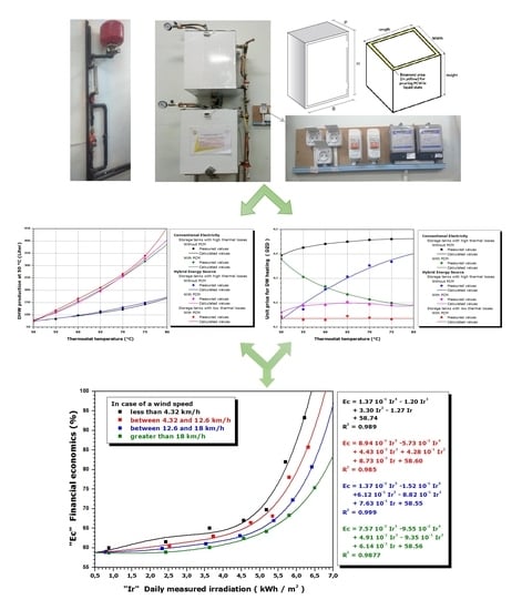
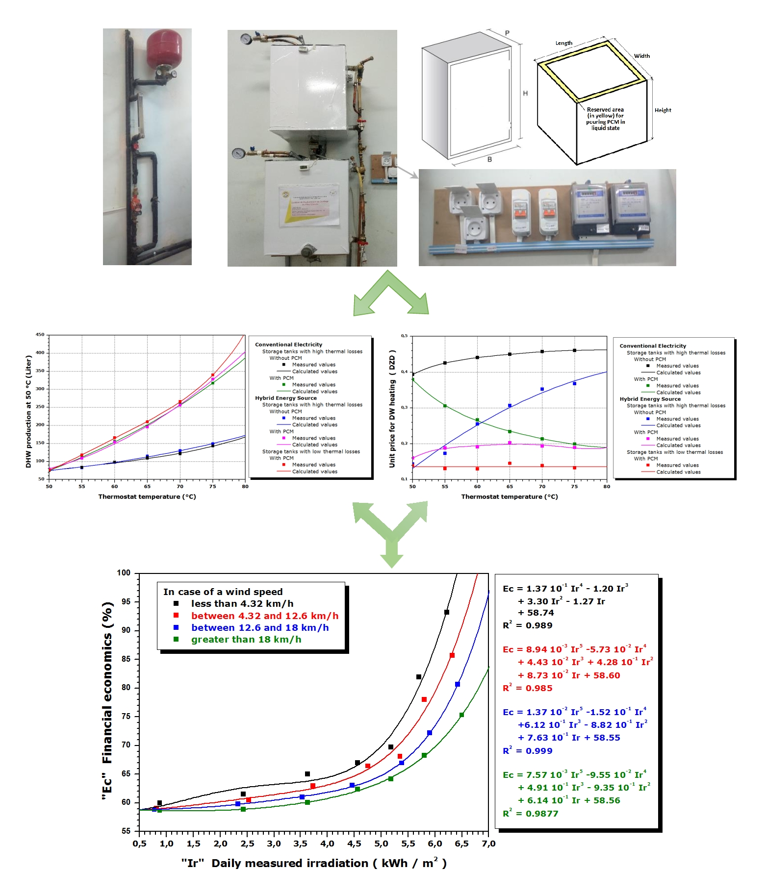
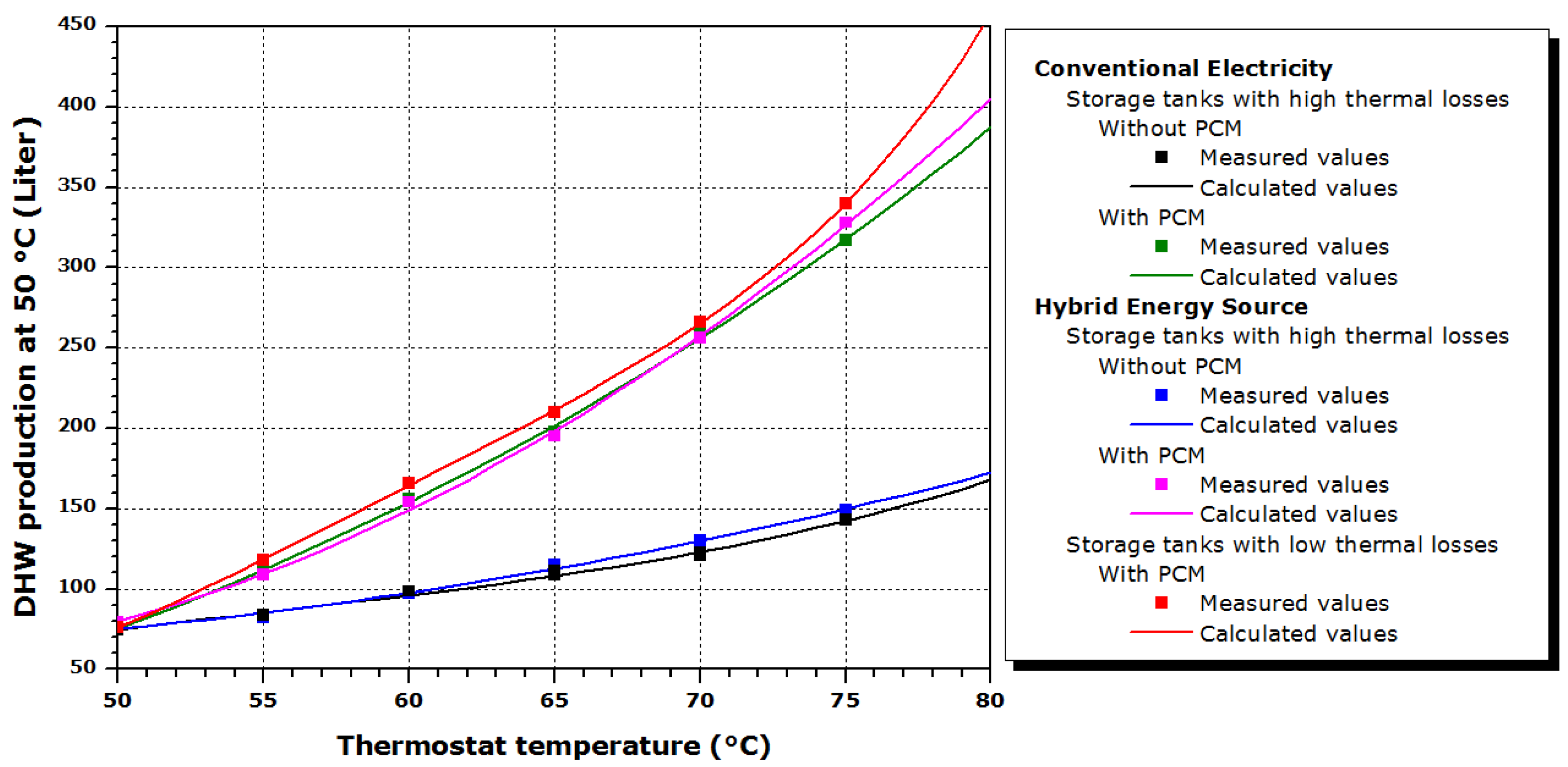
The capacity to experimentally produce hot water at 50 °C is calculated at the adjusted thermostat temperature. Additionally, it is possible to predict the values using the regression method. The regression curves can be used to estimate the effective production capacity of the domestic hot water at 50 °C for different water thermostat setpoints. The indicated values lead us thereafter to determine the quantitative gain in terms of domestic hot water production. The results in
Figure 7 are based on the solar collector’s inclination angle of 51°.
As clear from the figure for all cases, the capacity to produce hot water at 50 °C is proportional to the thermostat temperature. As the thermostat setpoint is increased, the hot water produced at 50 °C increases. It is also observed that the integration of PCM into the tank has promoted a considerable increase in the produced hot water compared to the conventional storage tank. At 68.61 °C thermostat setpoint, the amount of the produced hot water is doubled when the PCM is used.
Indeed, to calculate the water volume for a conventional tank, the resulting values of the mean values relative to the black and blue line profiles (refer to
Figure 7) were used. The same approach is adopted for the PCM-embedded storage tank; resulting values of the mean values relative to the green, pink, and red curves profiles were used. By assimilating the values of the produced hot water capacity to average values, it can be considered that the production of domestic hot water can increase at an estimated rate of 2.96%, 33.06%, 61.03%, 84.94%, 105.46%, 124.66%, and 145.06% for thermostat temperatures set at 50, 55, 60, 65, 70, 75, and 80 °C, respectively.
Another important observation is related to the amount of hot water produced at 50 °C, which is found to be independent of the nature of supply power sources (i.e., electric or hybrid). The amount of DHW production at the set point of 50 °C is equal for the systems with and without PCM because PCM melting occurs at a higher temperature of 52 °C and latent heat cannot be used. The figure shows that the produced hot water at 50 °C for the PCM-embedded tanks is almost the same for the electric and the hybrid energy source. For the conventional storage tank with high thermal losses, the difference between the quantities of water heated by electric energy and that from the hybrid energy source (solar energy + electricity energy as a supplement) is, on average, 3.82 L. The difference between the quantities of water represents, on average, 3.04% compared to the quantity produced by electrical energy and 2.91% compared to that produced by hybrid energy. This difference represents between 0.03% and 5.77% compared to the amount produced by electrical energy and gradually varies from 0.03% to 5.45% of the produced DHW amount from the hybrid energy source system.
Moreover, in the case of a storage tank with high thermal losses coated by one PCM layer on its sidewall, the difference between the hot water quantities produced by electrical energy and those from the hybrid energy source is, on average, 5.20 L. Likewise, the difference between the amount of water is, on average, 2.40% of the quantity produced by electrical energy and 2.38% compared to that produced by hybrid energy. Similarly, this difference, expressed in liters, represents between 0.10% and 6.13% of the DHW quantity produced by electrical energy and between 0.10% and 5.78% of the DHW amount produced by hybrid energy.
In the case of the PCM storage tank, it was noted that the tank with good thermal insulation (i.e., the red curve in
Figure 7) provided more hot water production compared with other PCM-embedded tanks with high losses (i.e., pink and green curves in
Figure 7).
3.3. Energy Cost of the Storage Tanks with/without PCM Using Different Energy Sources
Based on the results, it is possible to deduce that the quantity of hot water is independent of energy sources (i.e., electric or hybrid). Therefore, economic feasibility is deemed important. The electrical energy demand for hot water varies based on occupants’ number and behavior. The estimated cost for producing one liter of hot water (unit price) at 50 °C was calculated by dividing the electrical power required (measured by the two electric meters) to heat up the volume of the produced hot water. The energy cost is assumed at 10.54 DZD/kWh, knowing that 1 American dollar (USD) = 142.91 Algerian dinar (DZD). The energy cost for the five design cases is shown in
Figure 8. The energy cost for water heating is expressed as a function of the thermostat temperature. It is worth mentioning that the solar collector is tilted at 51°, which is the optimum tilt angle during the month of testing.
3.3.1. Energy Cost of the Electrical Storage Tanks with/without PCMs
For this scenario, two storage tanks with high thermal losses are using electricity as the main energy source. One is without PCM (i.e., the black line in
Figure 8), and the other is with PCM (i.e., the green line in
Figure 8). The former tank design shows a high energy consumption as the thermostat setpoint is increased. The poor insulation prevents the water in the tank from staying at the desired temperature. The heating energy consumption has increased by 17.08% when the thermostat setpoint is increased from 50 °C to 75 °C. On the other hand, the PCM-embedded storage tank has positive results. As the thermostat setpoint is increased, the heating energy cost is decreased. For instance, the heating energy cost for the PCM-embedded tank is 3.69% lower than the energy cost of the tank without PCM at 50 °C. The reduction in energy cost is higher at a higher thermostat setpoint. At 80 °C thermostat setpoint, the heating energy cost for the PCM tank is 58.85% lower than the tank without the PCM. Despite the enhanced performance of the PCM-embedded tank compared to the tank without PCM, both tank designs suffer from high thermal losses. Therefore, thermal insulation should be an integral element in the design of these tanks.
3.3.2. Energy Cost of the Hybrid (Solar/Electric) Storage Tanks with/without PCMs
Three design scenarios are evaluated using a hybrid energy source: a high thermal losses tank with PCM (i.e., the pink line in
Figure 8), another without PCM (i.e., the blue line in
Figure 8), and a third design that has low thermal losses with PCM (i.e., the red line in
Figure 8). The hybrid storage tank versions have electric heating as a backup, yet solar energy is the default energy source whenever available. The benefit of PCM is evident for the tanks with a hybrid energy source, as illustrated in
Figure 8. In particular, the storage tanks with PCM (i.e., the pink and red color lines) show that the energy cost is independent of the thermostat setpoint. The constant difference between these two tanks is due to the thermal insulation, also showing the importance of insulating the tanks. It is also noted that the difference between the electrical and the hybrid PCM-embedded tanks becomes smaller at a higher thermostat setpoint. At a higher thermostat setpoint, the use of electrical energy in the hybrid system becomes dominant over solar energy. On average and beyond 56 °C thermostat setpoint, the hybrid storage tank with high thermal losses and PCM reduced the energy cost by 57.16% compared to the conventional electrical storage tank without PCM.
On the other hand, the energy cost of the tank without the PCM increases as the thermostat setpoint increases. It is also interesting to note that as the thermostat setpoint increases beyond 60 °C, the energy cost of the tank without PCM using a hybrid source (i.e., the blue line in
Figure 8) is higher than the energy cost of the PCM-embedded tank using electric energy (i.e., the green line in
Figure 8), emphasizing the benefits of using PCM for DHW. At 50 °C setpoint, the hybrid storage tank (i.e., the blue line in
Figure 8) provided 66.55% lower energy cost than the same tank configuration with electric energy (i.e., the black line in
Figure 8). This reduction becomes lower as the thermostat setpoint increases until it reaches 13.22% at 80 °C.
3.3.3. Summary
In general, the best configuration corresponds to the hybrid heating system with a low heat loss PCM-embedded storage tank that has electrical energy as a backup. The incorporation of these two concepts (PCM + solar energy) via a well-insulated 80 L tank resulted in an energy cost reduction between 65.39 and 70.56%. For this option, the energy cost is stabilized at 0.1362 DZD/L regardless of the thermostat setpoint, as shown in
Figure 8.
4. Impact of Environmental Conditions on the Performance of the Hybrid PCM-Embedded and Insulated Tank at TThermostat = 75 °C
According to
Figure 8, the cost required to electrically heat one liter of stored water in the base case of a high-thermal losses tank (non-isolated storage tank) is estimated at 0.4608 DZD/L, the integration of the PCM plates in the side walls leads to a reduction of 58.56% in electrical energy cost. In fact, by referring to the hourly data for an entire year, it has been shown that it is possible to project the achieved savings when considering the climatic conditions of the region. The energy savings that will be obtained following the integration of PCMs will, therefore, not be less than 58.56%.
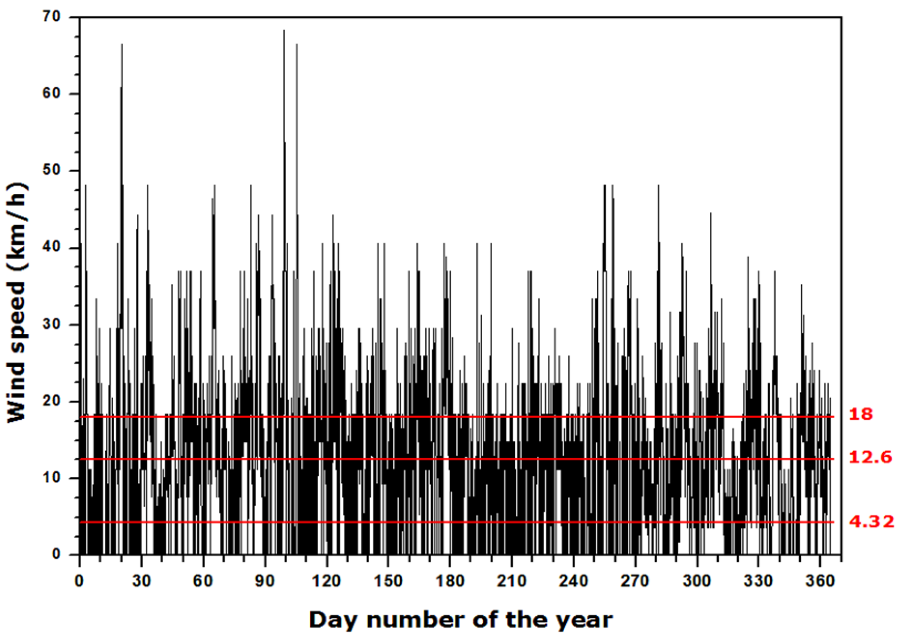
4.1. Influence of the Wind Speed
The wind is known to be a prominent factor in convective heat transfer. Hence, the performance of the solar collector may be influenced by the wind speed due to the natural convection. The hybrid PCM-embedded and insulated tank is used to analyze the impact of wind speeds on the performance of the tank.
For the first trials and during the experiments, the wind speed was measured to be between 12.6 km/h and 18 km/h with an overall clear sky. The experimental results indicated that an energy cost saving of 66.06% was achieved, an additional 7.5% (66.06–58.56%). The wind effect is slightly less sensitive if the sky is completely clear at the same wind speed range. The energy cost saving is recorded at least 67.02%, an additional 8.46% (67.02–58.56%).
The storage efficiency was also evaluated when the wind speed was between 4.32 km/h and 12.6 km/h. The results indicated that the tank could achieve energy cost savings of 67.5% and 69.03% for a generally clear sky condition and for a completely clear sky condition, respectively. When the wind speed was greater than 18 km/h, the energy cost savings was 63.06% for an average wind speed that approached 45.86 km/h. These percentages represent the least favorable values adopted after several experimental tests.
4.2. Influence of the Solar Intensity
The intensity of the received solar irradiance depends on the year, the sky cloudiness, the tilt angle of the surfaces, and the site. The sky is generally characterized according to the total cloud cover “N”, which is defined as the fraction of the covered sky by all the visible clouds. It is measured in oktas, one okta equal to one-eighth of the celestial vault. It is usually estimated by an observer, sometimes using dark eyeglasses to avoid reflections. However, total cloud cover can be estimated by a measuring instrument for assessing solar irradiance components at the horizontal surface. The clarity index “Clar” is expressed in accordance with the following formula [
48] (CCO, 2022):
E
global and E
diffus represent global horizontal and diffuse solar irradiances (Wm
−2), respectively. It is likely to have a sunny, veiled, cloudy, or overcast sky, but it is possible to have different intensities for the same type of sky. Veiled skies can be observed in the presence of cirrostratus clouds. In general, the appearance of the veiled sky will be in the milky form due to these clouds, which are extended but not very thick, and it is possible to see the sun through them. For instance, in the city of Conflans-en-Jarnisy, located in the north of Meurthe, and Moselle in the center of Lorraine in France, a classification according to two radically different periods can be assigned. The site is at a latitude of 49.17°, a longitude of 5.85°, a minimum altitude of 185 m, a maximum of 226 m, and an average of about 200 m. Summer (21 June) and winter (21 December) solstices were used as examples [
48,
49].
Table 8 shows a method that can be used to classify a sky by deducting the total cloud cover and knowing the peak solar irradiance and the irradiation.
For the same total cloud cover, a drastic fall in irradiation due to the year season can be obtained. For this case, it is extreme and near 84.92%. In order to achieve our own predictions, the experimental classification must therefore be carried out in accordance with the solar radiation intensity reflected by the daily solar irradiance. A series of experimental tests, which are a renewal of the same previous protocol but with other external weather conditions, allowed us to suggest the results of
Table 9.
The saving rate of financial needs, therefore, depends heavily on this intensity. For each case, at least three tests under almost equivalent solar irradiances and generally at the same wind speeds were carried out; the least attractive value will be retained. Taking the sky subjected to solar irradiance between 6.53 and 6.87 kWh and a low wind speed (less than 4.32 km/h) as an application example, four tests following the same experimental protocol have shown that the financial savings were 72.62%, 69.72%, 71.5%, and 69.99%. A value of 69.72% has been assigned. The intensity of the sun’s radiation received on the ground depends on the site, the inclination angle, and the sky state. Suppose all conditions are unfavorable (very high wind speed and very low solar intensity). In that case, the effect of the whole concept (PCM + solar energy) will be limited to only the PCM effect; the financial saving equivalent to a thermostat temperature of 75 °C cannot be below 59.50%.
4.3. Forecast and Projected Operating Results
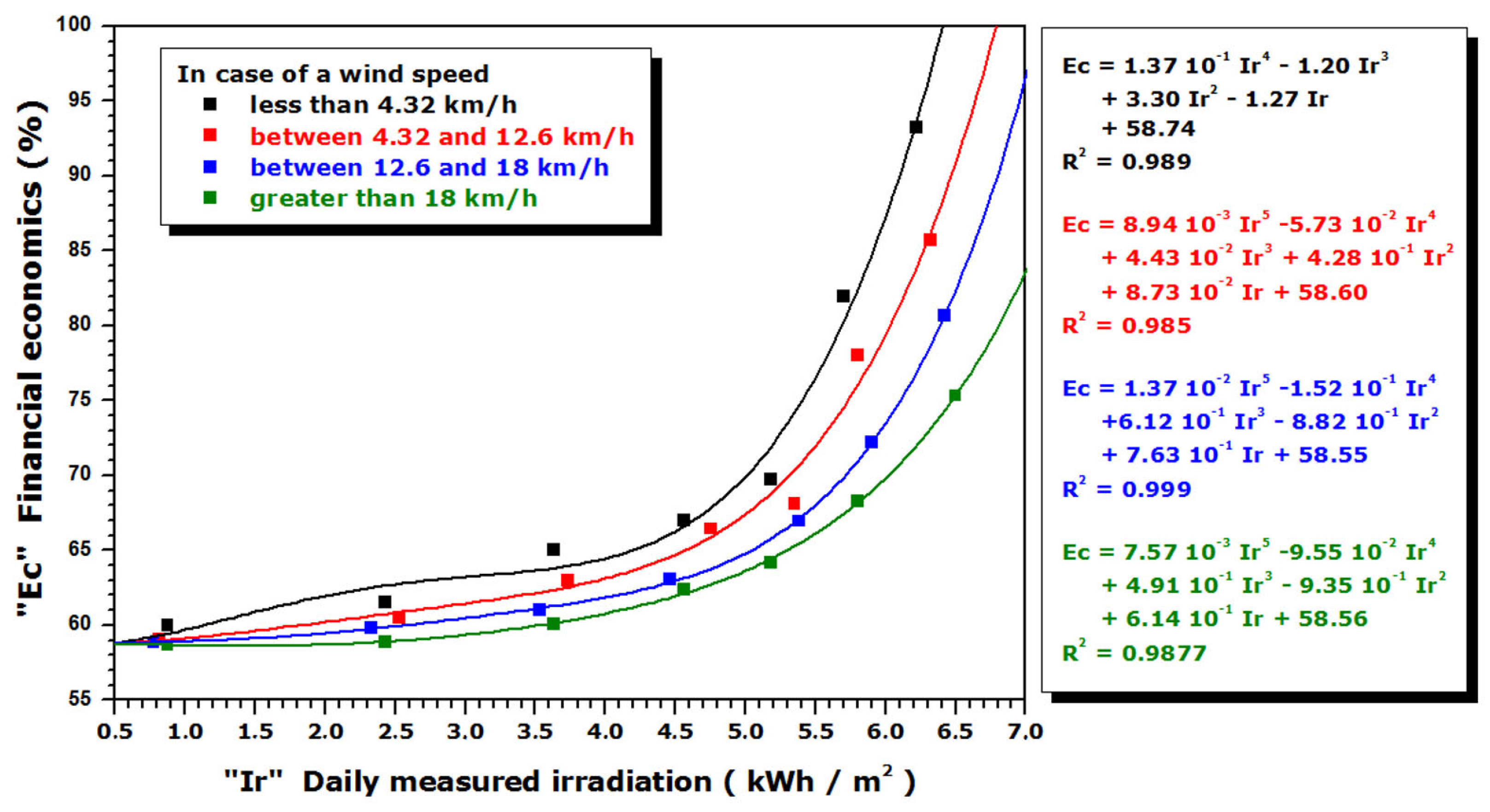
The purpose of the calculations and financial forecasts was to generalize the results. Following these experimental results, a figure can be drawn, including actual and predicted values of the financial savings achieved by using a hybrid solar/electric system containing a low heat loss PCM storage tank. The prediction (from the conducted calculations) of the financial savings compared to our reference case (a unit price of 0.4608 DZD/L) was obtained on the basis of the polynomial polishing technique from the measured values. The previous experimental method has always been applied and respected to deduce the experimental (measured) value of the financial savings. That is to say, by activating the hybrid water heating system at 75 °C (in the case of the hybrid PCM-embedded and insulated tank), it is possible to obtain the quantity of hot water produced at a usable temperature of 50 °C and the electricity consumption required to reach the set temperature of 75 °C. It is then possible to calculate the unit price, which is the ratio between the product (electrical consumption required for the quantity of water produced x cost equivalent to 1 kWh) and the quantity of water produced. The obtained value of the reduction rate (reduction of this last unit price compared to 0.4608 DZD/L expressed as a percentage) is a value to be considered for the polynomial interpolation, which was called the measured value. For more precision in the prediction, the protocol was repeated several times for a single case under similar external conditions. The retained value was the lowest and is therefore represented by points in
Figure 9. Each point of this figure corresponds to a financial saving (reduction of the equivalent unit price) expressed as a percentage after several tests of similar external conditions that differ from the corresponding conditions at other points.
In
Figure 9, the values correspond to the minimum percentages from several experimental tests for the same conditions. The methodology has allowed us to ensure that the obtained financial savings are undoubtedly consistent and reliable. These values may be more interesting (slightly higher) than those of the selected values, but it is impossible to have values below these retained values. The non-linear regression functions are in the curve adjustments form.
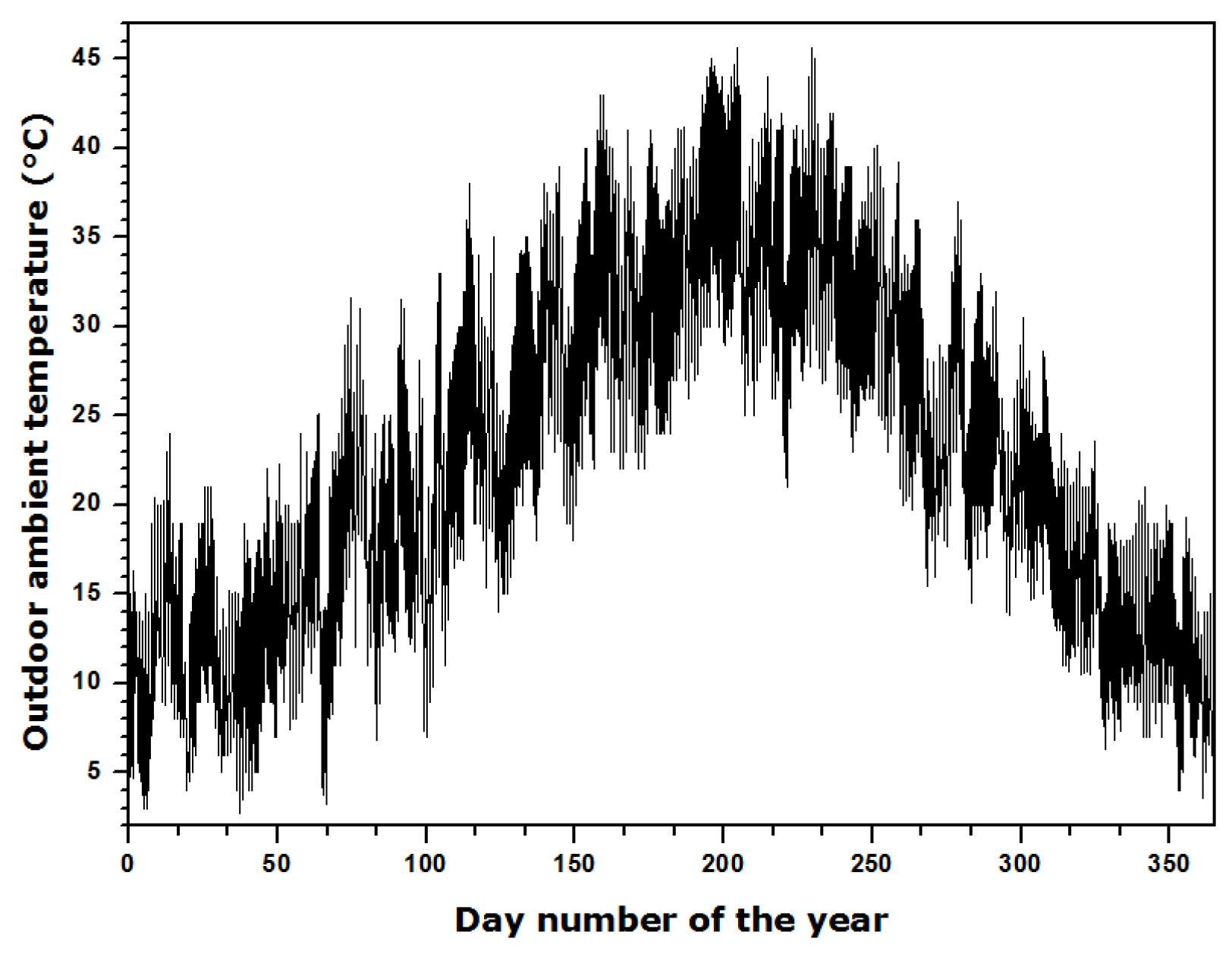
In contrast to the solar intensity and the wind speed, the effect of the outside ambient air temperature on financial savings is generally very small. Using the results obtained from
Figure 9, and on the basis of the curves of the representative climatic conditions represented by
Figure 10,
Figure 11 and
Figure 12, the results can be generalized to the annual basis as outlined in
Table 9. This database was collected from the radiometric station of the Ghardaïa research unit [
50,
51].
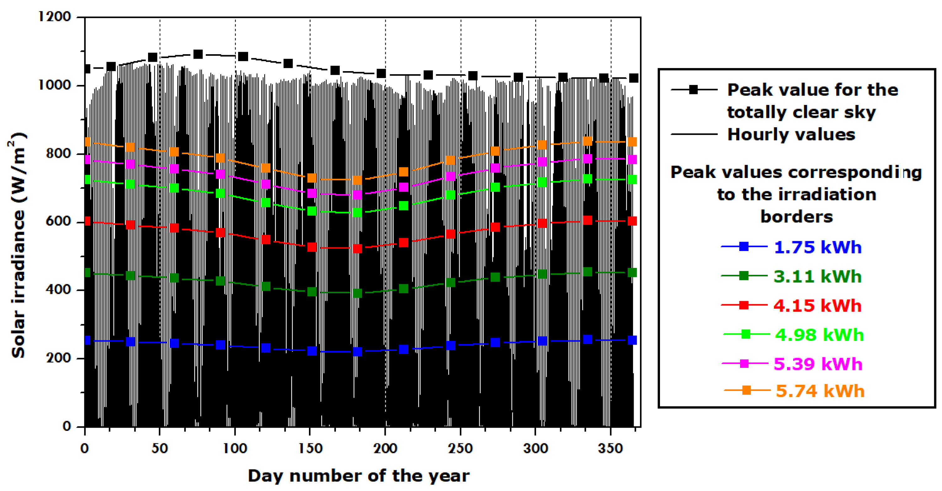
To achieve the best energy cost savings, it is desirable to convert the horizontal solar irradiances to the solar irradiances incident on surfaces at an optimal tilt, which may vary from month to month, as shown in
Table 10. The values were determined using the Perrin de Brichambaut approach [
39,
46]. This method allowed us to draw on
Figure 12, the extreme values corresponding to the optimum inclination for the totally clear sky (black lines) and the already indicated values for the edges of solar irradiances.
The database indicates that the Ghardaïa climate is a desert climate with mild and very cold winters at night and very hot and sunny summers. Sky conditions and radiation are clear for much of the year, but winds are frequent.
The equivalent savings for each month in
Table 9 are calculated using the following relationship:
where i: the number of the case, n: is the total number of cases, and the total number of days = 365.
According to
Table 10, the annual average clarity index is estimated to be 86.58%. Indeed, by adopting the average optimum inclination of the surface on a monthly basis, potential yearly average savings of at least 80.25% may be achieved. The wind speed will reveal the difference in the expected monthly savings if the monthly average of the irradiation inclined at the monthly average of the optimal tilt angle is globally close and stable. The most suitable months are those characterized by a high solar intensity reflected by an optimized receiving surface and a relatively low average daily wind speed compared to other months. In this case, financial savings may exceed 80%. In July, August, September, and December, the average savings were 84.45%, 83.81%, 83.65%, and 82.64%, respectively.
However, it should be noted that despite the drop in average irradiation to 5.58 kWh/day in December, the saving rate always remains important due to the average daily wind speed, which is low during this month. The main drawback of a flat plate collector is its front convective heat loss which is significant at high wind speeds. The second weakness of the flat collector in the winter is that it requires a better inclination; this situation sometimes creates a more difficult configuration to implement.
The addressed objective was first to recover PCM materials and use them as an alternative raw material that can be reintegrated into the DHW heating process. Furthermore, if the annual DHW electrical needs correspond to a consumption of 3799.5943 kWh/year (equivalent to 250 L of hot water per day), the annual bill to be paid (10.54 DZD per kWh) is therefore 40 047.72 DZD per year. If the hybrid-energy heating system is used, the cost of heating the water is 0.1362 DZD per liter under clear skies. This case is valid at 86.58% (316 days) for the entire year. The other days (for the sky of any type) correspond at least to the worst case (totally overcast sky, case of a PCM tank with low heat loss), which relates to an invoice of 0.2 DZD per liter. The installation, therefore, results in a reduction in annual requirements of almost 67%. (0.1362 DZD × 250 L × 316 days) + (0.2 DZD × 250 L × 49 days) = 13,209.8 DZD.
5. Conclusions
The electric water heater is one of the simplest solutions for DHW application, but it consumes a significant amount of energy and requires regular maintenance. Installing a customized solar water heater in a sunny region can present a better alternative since it uses clean and inexhaustible energy. However, solar may also be intermittent during the day. Phase change materials (PCMs) have shown the potential to elongate the use of solar energy and flatten the supply of energy at a constant temperature setpoint.
The efficiency of this DHW system depends mainly on the incident solar irradiation, which is thus transformed into thermal energy and then into the water circulating in the entire heating system. The higher the area of the water collector exposed to sunlight, the greater the production of hot water. Thereafter, the wind speed will certainly cause differences in collector efficiency if the solar irradiation is of the same magnitude. The increase in wind speed leads to a decrease in the performance of the solar collector and therefore the entire heating system. From the obtained results, the correct incorporation of this new PCM in the hot water storage tank can limit the intermittent problem due to solar energy use. It has helped to maintain a higher hot water temperature, which leads to better efficiency and financial savings.
Based on experimental observations, the issue of water overheating inside the flat water solar collector has not been encountered, even with an optimal inclination. The water temperature has never reached the boiling point of 100 °C. As for the water in the tank, the thermostat operates automatically, but we can manually adjust its temperature to suit the user’s preferences. The experimental results indicated that the best configuration corresponds to the hybrid heating system containing an insulated PCM-embedded storage tank. Regardless of the thermostat setpoints, the energy cost was stabilized at around 0.1362 DZD/L (i.e., 0.00096 USD/L) of hot water. The energy cost savings ranged between 65.39 and 70.56% (on average 69.26%) compared to the conventional hot water storage tank. On an annual basis, this novel tank configuration may achieve an average energy cost savings of 80.25% when the tilt of the flat plate solar collector is optimized on a monthly basis. The monthly variation of the tilt angle of the collectors was economically justifiable. In case of insufficient sunlight, the heat is produced by a backup electrical heater.
In the Algerian Sahara, there is great potential for the development of combined solar systems. These thermal water heating systems are more suitable in areas with high solar radiation and can easily replace conventional systems. As it was expected, financial savings are greatest during the summer months due to the high insolation. The highest potential savings to be achieved using the hybrid heating system are 84.45% in July, while the lowest potential savings are 77.29% in December.
The payback period can be viewed as a future objective, knowing that the investment or the additional expenses (the new material, which is a mixture of paraffin and grease) will be very low compared to the seasonal or annual financial gain. A further enhancement of this configuration may be achieved by using vacuum tube solar collectors to reduce the convective heat transfer that could be dominant in flat plate collectors.


 ,
, 


