Article

Investigations into the Flexural-Torsional Buckling Behavior of Steel Open-Section Beam-Columns

by
Anna M. Barszcz
1,
Marian A. Gizejowski
1 and
John P. Papangelis
2,*
1
Department of Concrete and Metal Structures, Faculty of Civil Engineering, Warsaw University of Technology, al. Armii Ludowej 16, 00-637 Warsaw, Poland
2
School of Civil Engineering, University of Sydney, Sydney, NSW 2006, Australia
*
Author to whom correspondence should be addressed.
Buildings 2023, 13(2), 307; https://doi.org/10.3390/buildings13020307
Submission received: 9 December 2022 / Revised: 11 January 2023 / Accepted: 13 January 2023 / Published: 19 January 2023
(This article belongs to the Special Issue Advances in the Behaviour of Steel Structures)

Abstract

:
This paper is in the field of elastic flexural-torsional buckling of steel beam-columns of bisymmetric narrow-flange and wide-flange I-section shape. Investigations are focused on the derivation of the strain components and the energy equation, based on the displacement-field formulation in the deflected configuration. At the same time, a review of analytical solutions based on the classical and refined energy-equations are summarized, presented and discussed. The relationship between the maximum in-plane bending moment and the compressive force of beam-columns is the main objective of this research investigation. Simple boundary conditions of end-sections free to deflect and to warp are considered, together with an arbitrary loading-pattern. The principle of superposition and the moment amplification rule for considering the second-order effects are widely used. The main conclusions are drawn in relation to the flexural-torsional resistance-evaluation design of steel beam-columns in modern design codes for steelwork.

1. Introduction

Steel beam-columns of double-tee section shape that are initially straight and untwisted, and subjected to compression and bending about the major principal axis y-y, exhibit failure-modes either in the plane of bending by deflecting along the oz axis, or out of that plane by deflecting laterally along the oy axis and by twisting about the member axis ox. The former failure-mode is related to the second-order bending that at the ultimate limit state corresponds to the member in-plane buckling resistance. In contrast, the latter failure-mode is associated with the bifurcation instability in the form of out-of-plane buckling that at the ultimate limit state corresponds to the flexural-torsional buckling (FTB) resistance.
The in-plane behavior and flexural-torsional buckling of beam-columns have been studied for many years, starting with the first solution obtained by Euler for flexural buckling of compressed elastic members, and then extended from the in-plane field of studies into the torsional and general flexural-torsional failure domains, including the elastic range of steel behavior, and then taking into account the elastic–plastic properties of steel. Problems related to different aspects of beam-column stability behavior are included in many textbooks, e.g., Timoshenko and Gere [1], Vlasov [2], Chen and Atsuta [3,4], Trahair [5], Yang and Kuo [6], and finally Trahair et al. [7] and Kindmann and Kraus [8], which are specifically related to the behavior of steel members and structures. For standardization purposes, the elastic-buckling solutions based on linear-buckling analysis (LBA) derived from the classical energy-equation are adopted.
In LBA of beam-columns under compression and major-axis bending, the small-rotation matrix is used for the formulation and evaluation of the first order stress resultants (the axial force and the major-axis bending moment). The displacement-field may be formulated in this case for the configuration being infinitesimally close to the initial one. Adopting an RHS Cartesian coordinate system, in which the axis ox is the prismatic-member axis passing through the section shear-center, axes oy and oz are the section principal-axes (oy is prescribed for the section’s greater moment of inertia and for the major bending-axis, and oz is associated with the plane of the loading system), the displacement-field takes the form given by Pi et al. [9]:
u v w u 0 v 0 w 0 = R ω θ x y z 0 y z
where u, v, and w are the displacements of an arbitrary point within the member volume, the vector of u 0 , v 0 , and w 0 contains the member-axis displacements of the bisymmetric open section, resulting from the elongation and rotations of the member’s elemental-length dx, ω is the section’s normalized warping-ordinate, θ x is the angle of twist rotation, and = d / d x is the derivative of the x-dependent variables.
The first-order rotation matrix, R , in the undeflected configuration is given by:
R = 1 θ z θ y v 0 1 θ x w 0 θ x 1  
where θ y = w 0 and θ z = v 0 are the angels of flexural rotations.
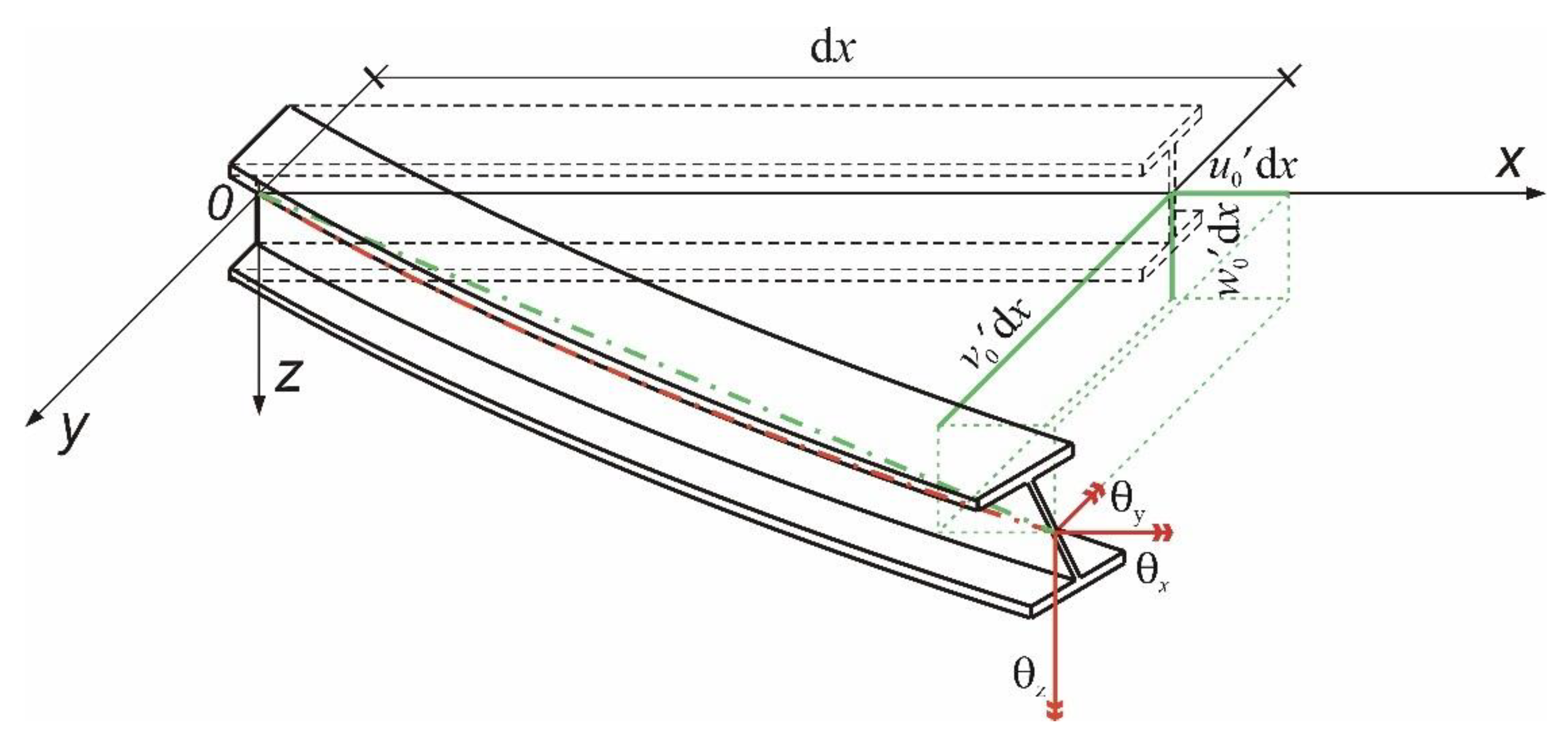
Figure 1 shows the kinematics of the member elementary-length, dx, based on the first-order rotation matrix given by Equation (2).
For the purpose of stability formulation, the second-order rotation matrix may be adopted, in which the coupling between the twist rotation and the flexural rotations is taken into consideration for the evaluation of the displacement-field:
R = 1 1 2 v 0 2 + w 0 2 v 0 w 0 θ x w 0 + v 0 θ x v 0 1 1 2 w 0 2 + θ x 2 θ x w 0 θ x 1 1 2 v 0 2 + θ x 2  
As a result, the classical energy-equation is obtained by using such a form of the rotation matrix as is explained in Pi et al. [9]. A closed-form solution for FTB problems can only be obtained for the cases of uniform bending and uniform compression. For a symmetric-loading system, the solution is obtained by approximating globally the buckling displacements with the use of the functions satisfying the natural boundary conditions
v 0 = a 1 sin π x L 0 = a 1 sin π ξ
θ x = a 3 sin π x L 0 = a 3 sin π ξ
in which the dimensionless coordinate ξ = x / L 0 and L 0 is the original length of the straight, untwisted member.
The linear-eigenvalue analysis (LEA) closed-form solution for beam-columns for the case of equal and opposite end-moments, M y , and compression, N, takes the well-known form
M y M c r , 0 2 = 1 N N z 1 N N T
where M c r , 0 = i 0 N z N T is the critical moment for uniform bending, N z and N T are the lowest bifurcation forces in relation to the independent out-of-plane buckling modes of flexural minor-axis form and torsional form, and i 0 is the polar radius of gyration.
Cuk and Trahair [10] developed an improved analytical FTB-solution for elastic beam-columns under unequal end-moments:
M y , m a x C b c M c r , 0 2 = 1 N N z 1 N N T
where C b c is the equivalent uniform moment-modification-factor and M y , m a x is the end- moment of greater absolute value.
Replacing the C b c factor by C b c , 0 , which is valid for any shear-center loads, not only for unequal end-moments, the latter takes the following form:
  C b c , 0 = M y , s , m a x M y , m a x   1 C b s + M y , a , m a x M y , m a x 3 1 C b a 1 0.575 N N z 1
where M y , s , m a x , M y , a , m a x are the maximum moments related to the symmetric- and antisymmetric-system load-components and C b c , 0 is the factor for any combination of end-moments and shear-center loads.
The factors C b s = 1.0 and C b a = 2.5 proposed by Cuk and Trahair [10] for unequal end-moments correspond to those calculated from the equation provided by Serna et al. [11].
Combined-load cases need a more complex analysis that nowadays is performed using LBA and the finite-element method leading to LEA, e.g., Papangelis et al. [12]. In parallel investigations, a number of LEA formulations have been researched in order to obtain analytical elastic-buckling solutions for engineering applications. The approximate solutions for moment-gradient cases may be obtained by using the following global approximation of buckling modes:
v 0 = v 0 s + v 0 a = a 1 sin π x L 0 + a 2 sin 2 π x L 0 = a 1 sin π ξ + a 2 sin 2 π ξ
with θ x given by Equation (5).
An LEA formulation and a general closed-form solution were presented by Giżejowski et al. [13]. Such a general solution for the shear-center span loads takes the form of Equation (7), in which C b c = C b c , 0 :
C b c , 0 = M y , s , m a x M y , m a x   1 C b s , c e m 2 + 1 N N z 1 N N z a M y , a , m a x M y , m a x 1 C b a , c e m 2 0.5
where 1 C b s , c e m = 2 0 1 M y , s ξ M y , s , m a x sin 2 π ξ d ξ , 1 C b a , c e m = 2 0 1 M y , a ξ M y , a , m a x sin π ξ sin 2 π ξ d ξ are reciprocals of the classical energy-method conversion-factors; M y , s ξ , M y , a ξ are the field-moments for the symmetric and antisymmetric components, and N z a = 4 N z is the second-lowest flexural minor-axis bifurcation force.
The out-of-plane stability LBA formulation was further extended for the inelastic region. Bradford et al. [14] presented a finite-element model for investigating the inelastic behavior of beam-columns. A large-displacement inelastic in-plane analysis was combined with the formulation of a non-prismatic elastic-line finite element with 7 degrees of freedom. An out-of-plane inelastic-buckling analysis was carried out for the evaluation of inelastic critical-loads for beams and beam-columns under selected in-plane loading systems. The effect of residual stresses was taken into account in the finite-element analysis, but the effect of geometric imperfections was not included.
Recently, a number of published papers have referred to more accurate nonlinear-buckling-analysis (NBA) formulations that include the effect of prebuckling displacements on the buckling state. Pi and Trahair [15,16] presented a general numerical model for nonlinear-buckling analysis (NBA,) using a beam finite-element approach. Pi and Bradford [17,18] continued these investigations, presenting an accurate rotation matrix that satisfies the orthogonality conditions
R R T = I ,
det R = 1 .
The terms of the rotation matrix are as follows:
R   1 , 1 = cos θ ,
R   1 , 2 = v 0 cos ϕ + w 0 sin ϕ 1 + 2 e 0 0.5 ,
R   1 , 3 = w 0 cos ϕ v 0 sin ϕ 1 + 2 e 0 0.5 ,
R   2 , 1 = v 0 1 + 2 e 0 1 ,
R   2 , 2 = 1 λ v 0 2 1 + 2 e 0 1 cos ϕ λ v 0 w 0 1 + 2 e 0 1 sin ϕ ,
R   2 , 3 = 1 λ v 0 2 1 + 2 e 0 1 sin ϕ λ v 0 w 0 1 + 2 e 0 1 cos ϕ ,
R   3 , 1 = w 0 1 + 2 e 0 1 ,
R   3 , 2 = 1 λ v 0 2 1 + 2 e 0 1 sin ϕ λ v 0 w 0 1 + 2 e 0 1 cos ϕ ,
R   3 , 3 = 1 λ w 0 2 1 + 2 e 0 1 cos ϕ + λ v 0 w 0 1 + 2 e 0 1 sin ϕ ,
where e 0 = u 0 + v 0 2 + w 0 2 / 2 is the Green measure of the member-axis extension, and ϕ is the angle of twist rotation in the rotated axes, θ = 1 + u 0 1 + 2 e 0 0.5 and λ = 1 / 1 + cos θ .
Barszcz et al. [19] adopted the rotation matrix developed by Pi and Bradford [17,18] for the lateral-torsional buckling (LTB) of beams, and showed that it allows for the LBA solution in the form of a quadratic-eigenproblem analysis (QEA). In conclusion, it was mentioned that the LEA buckling-moment, M c r , needs to be modified by the factor k 1 0.5 , where k 1 = 1 I z / I y and I y , I z are the principal moments-of-inertia of the cross-section.
Mohri et al. [20] used another rotation matrix for the virtual-work formulation that allowed for the effect of prebuckling displacements on the beam-column buckling state, by using the k 1 factor. The trigonometric functions of the angle of twist rotation were retained in the formulation for the derivation process, starting from the rotation matrix and ending in the calculation of strain components and the equilibrium at the buckling state. The rotation matrix was presented in [20], in the following form:
R = 1 v 0 cos θ x w 0 sin θ x w 0 cos θ x + v 0 sin θ x v 0 cos θ x sin θ x w 0 sin θ x cos θ x .
Finally, one has to mention that for uniform bending and compression, a more accurate expression of the critical moment was presented by Trahair et al. [7]:
M y k 1 k 2 0.5 M c r , 0 2 = 1 N N z 1 N N T
where k 2 = 1 1 2 G I T / E I y 1 + E I w / G I T π / L 0 2 , E and G are the material’s elastic and shear moduli, and I w and I T are the section warping-constant for non-uniform torsion and the Saint-Venant’s constant for uniform torsion, respectively; for typical situations in steelwork, one may adopt k 2 = 1 .
The purpose of this paper is to investigate the mechanics of flexural-torsional buckling in a different way than has been presented in the subject literature. The derivation is based on the rotation matrix formulated in the deflected configuration with the aid of transformation matrices, in order to represent the deformation components at buckling. A significant element of this research is in laying down the development of a refined stability criterion for FTB equilibrium as the second variation of the total potential energy. The derived equations are valid for any asymmetric in-plane loading system. The stability criterion includes the effect covered by the k 1 factor, but neglects the effect covered by the k 2 factor. The solution is obtained in an approximate way by using the superposition principle of amplified symmetric and antisymmetric moment-components. The analytical solution developed is verified for selected symmetric- and asymmetric-loading systems. Two hot-rolled steel sections, IPE 180 and HEB 180, exhibiting the different values of k 1 = 0.920 for the former section and k 1 = 0.645 for the latter section, are dealt with. For the purposes of verification, two finite-element flexural-torsional-buckling-analysis software programs are used, namely PRFELB, developed at the University of Sydney [12] and LTBeamN, developed at CTICM [21], the latter available for free in the public domain. It is concluded that the developed elastic-buckling equation for any asymmetric-loading system is an extension of the solution presented in Mohri et al. [20]. The general solution developed in Mohri et al. [20], based on the differential equilibrium equations and Galerkin method, was restricted to symmetric-loading systems. The general solution developed in this paper applies to any asymmetric-loading system and to the selected symmetric-loading patterns proven by Mohri et al. [20].

2. Kinematics of an Open Bisymmetric-Section

Figure 2 shows the kinematics of the member’s axis length d s 0 = 1 + u _ 0 d x subjected to membrane extension/shortening in the deflected configuration of the double-tee bisymmetric section and the flexural deformations and torsion, during which the bowing and warping effects are considered.
The length of an arbitrary fiber, ds, in the configuration infinitesimally close to the deflected configuration is defined as:
d s = 1 + 2 e _ d x 1 + e _ d x ,
where e _ = u _ 0 + 1 2 v _ / x 2 + w _ / x 2 , u _ 0 is the axial displacement, v _ and w _ are the field displacements of an arbitrary material-point measured along the rotated axes in the deflected configuration, and / x ,   / y ,   / z are the partial derivatives of multi-ordinate dependent variables, herein with regard to the x, y, or z ordinate.

2.1. Displacement-Field

Using small-rotation measurements, and including the vector of rigid body translations u _ 0 , v _ 0 and w _ 0 of the member’s elemental-length dx, having a different meaning than the vector of those displacements in Equation (1), the matrix relationship for the displacement-field in the deflected configuration is proposed to be written as follows:
u _ v _ w _ u _ 0 v _ 0 w _ 0 = R   d x y z ω κ _ x y z
where κ _ x is the twist measured in the deflected configuration, and u _ is the axial-displacement of an arbitrary material-point measured along the rotated axes in the deflected configuration and the rotation matrix
R = e _ ϕ z ϕ y ϕ z cos ϕ x sin ϕ x ϕ y sin ϕ x cos ϕ x .
The first-column terms of R are to be multiplied by dx in order to obtain the arbitrary fiber incremental-elongation in the deflected configuration e _ d x = s x d x 1 and the incremental transverse-displacement measures along the member-section rotated axes: ϕ z d x = v _ 0 d x , ϕ y d x = w _ 0 d x , and ϕ x is the angle of twist rotation about the rotated-member x-axis. The relationship relating the displacements along the rotated axes to those along the axes in undeflected configuration is as follows:
  u _ 0 v _ 0 w _ 0 = 1 0 0 0 cos ϕ x sin ϕ x 0 sin ϕ x cos ϕ x u 0 v 0 w 0
Since the first column of the rotation matrix, after multiplying by ds, represents the vector of displacements along the rotated axes, Equation (25) may be restructured in the following form:
u _ v _ w _ u _ 0 v _ 0 w _ 0 = u 0 ω κ _ x + 1 2 v _ / x 2 + w _ / x 2 d x v _ 0 w _ 0 + R ϕ y z  
where the curvature-related rotation submatrix R ϕ   is
R ϕ = ϕ z ϕ y cos ϕ x sin ϕ x sin ϕ x cos ϕ x
The vector of rotation angles in the deflected configuration may be referred to those measured along the unrotated axes, as follows:
ϕ x ϕ z ϕ y = 1 1 2 w 0 1 2 v 0 0 cos ϕ x sin ϕ x 0 sin ϕ x cos ϕ x θ x θ z θ y
where θ y = w 0 / 1 + u 0 , θ z = v 0 / 1 + u 0 .
The curvatures in the deflected configuration are expressed as
κ _ x κ _ z κ _ y = 1 1 2 w 0 1 2 v 0 0 cos ϕ x sin ϕ x 0 sin ϕ x cos ϕ x κ x κ z κ y
where κ x = θ x is the twist curvature for the axes of the twisted, straight member, and κ y = 1 + u 0 w 0 u 0 w 0 and κ z = 1 + u 0 v 0 u 0 v 0 are the flexural-curvature measures for the deflected untwisted-axes.
The formulation developed herein maintains coupling between the membrane state of deformation and all the other deformation states, namely torsion as well as flexure, about both sectional axes. It is a similar formulation to that of Pi and Bradford [17,18] except that the latter neglect the coupling between the membrane- and torsion-states. Both formulations correspond to the so-called third-order member theory (large-displacement theory).
In the so-called second-order theory, the membrane strain, u 0 , is taken as a constant value for all the section fibers along the member axis; therefore, u 0 = 0 while d s 0 / d x = 1 + u 0 may be taken as equal to unity in the developed final relationships. As a result, the curvatures become κ _ y = κ y = w 0 , κ _ z = κ z = v 0 . Furthermore, when neglecting the nonlinear terms of the twist curvature, i.e., taking κ _ x = κ x = θ x , the formulation corresponds to that of Mohri et al. [20]. Although all the above formulations lead to a slightly different FEM model for nonlinear-buckling analysis (NBA), they result in the same non-classical energy-equation that constitutes the basis for allowing the effect of prebuckling deflections to be taken into account in the linear-buckling analysis (LBA).
The classical energy-equation may be obtained by replacing, at the early stage of derivation, the trigonometric functions with the first terms of the Taylor series expansion, i.e., sin ϕ x ϕ x , cos ϕ x 1 .

2.2. Strain and Total-Potential-Energy Components

The strain-energy stored in an open-section member results from two nonzero strain-components, normal ε and shear γ (the subscripts are left out for the convenience of notation). They are dependent upon the displacement gradients, in particular the curvatures, for bending about the sectional principal-axes and for torsion. Retaining the trigonometric functions of the twist rotation and neglecting terms of a higher order than 2, the displacement gradients with regard to the x-ordinate may be expressed in the deflected configuration, as follows:
u _ x v _ x w _ x = u 0 ω κ _ x + 1 2 v _ x 2 + w _ x 2 ϕ z ϕ y + x R ϕ y z
where
x R ϕ = κ _ z ϕ y κ _ x κ _ y + ϕ z κ _ x 0 κ _ x κ _ x 0 .
The nonzero normal and shear-strain measurements in the deflected configuration are defined as follows:
ε = d u _ d x = u 0 κ _ z y + κ _ y z ω κ _ x + 1 2 v 0 2 + w 0 2 + i 0 2 κ _ x 2
γ = 2 n κ _ x
where n is the section coordinate across the wall thickness measured from the mid-surface line, and being normal to it.
The total potential energy Π is composed of the positive strain-energy U and the negative work of the conservative load-system during the member deformations, W . The strain-energy for the elastic beam-column is given by
U = 1 2 0 V 0 σ τ δ ε γ d V = 1 2 0 V 0 ε γ E 0 0 G δ ε γ d V
where V 0 is the volume of the straight, untwisted member.
The work, W, of a conservative loading-system of applied loads and moments from the straight, untwisted state, may be written as
W = 1 2 0 L 0 q x q y q z u q v q w q + m a p l , x m a p l , y m a p l , z θ x θ y θ z d x + Q x Q y Q z u Q v Q w Q + M a p l , x M a p l , y M a p l , z θ x , M θ y , M θ z , M .
where q k , Q k for k = x,y,z—applied distributed and concentrated conservative-loads, u q , v q , w q —displacement-field components corresponding to the conservative distributed-load components, u Q , v Q , w Q —displacement-field components corresponding to the conservative concentrated-load components, m a p l , k , M a p l , k —applied distributed- and concentrated-moments, θ x , θ y , θ z and θ x , M , θ y , M , θ z , M —rotation-field components corresponding to the distributed and concentrated conservative-moments, respectively.
Equating the first variation of Π to zero gives the variational equilibrium equation that may be used for the establishment of the differential equilibrium equations as well as the sets of natural-boundary conditions and stress resultants. Considering that A is the cross-section area, and retaining the terms belonging to the flexural-torsional buckling of beam-columns under bending about the major axis and compression, the in-plane stress resultants at the buckling state were predicted by Mohri et al. [20]:
N = E A u 0 ,
M y = E I y w 0 ,
M z = E I z w 0 θ x .
Consider a special loading system, composed of transverse-span loads along the oz axis and unequal end-moments about the section’s principal major-axis, producing bending in the plane of the section’s greater moment-of-inertia, as well as equal and opposite end-loads along the ox axis producing tension/compression. Loads q z are composed of “i” distributed q z , i components and loads Q z of “j” concentrated Q z , j components. All the components are unequal in the member half-lengths, as shown in Figure 3. The load-system asymmetry in both member half-lengths is represented by the load factors ψ q , i and ψ Q , j , as well as by the factor ψ M for end-moments. For the convenience of further calculations, this in-plane loading system is decomposed into symmetric and antisymmetric components, as is also shown in Figure 3.
Considering the described in-plane loading system, the variational equilibrium equation at the FTB state becomes
1 2 δ 0 L 0 { E I y ( k _ y ) 2 + E I z ( k _ y ) 2 + G I T ( k _ x ) 2 + E I w ( k _ x ) 2 + E A u 0 [ ( v 0 ) 2 + ( i 0 ) 2 ( k _ x ) 2 ] } d x + δ { i x q 1 , i x q 2 , i q z , i z q , i [ θ x , i ( x ) ] 2 d x + j Q z , j z Q , j [ θ x , j ( x Q , i ) ] 2 + i L 0 x q 2 , i L 0 x q 1 , i ψ q , i q z , i z q , i [ θ x , i ( x ) ] 2 d x + j ψ Q , j Q z , j z Q , j [ θ x , j ( L 0 x Q , j ) ] 2 } = 0 .

3. Stability Condition in Deformed Configuration

The stability condition at member equilibrium in the deflected configuration is derived by calculating the second variation of Π and equating the result to zero. This can be done by performing the variation of Equation (41) and substituting the definitions of stress resultants that yield the criterion based on the so-called refined energy-equation:
1 2 0 L δ 2 { E I z ( v 0 ) 2 + E I w ( θ x ) 2 + G I T ( θ x ) 2 N [ ( v 0 ) 2 + i 0 2 ( θ x ) 2 ] + k 1 M y θ x ( 2 v 0 M z E I z ) } d x + δ 2 { i x q 1 , i x q 2 , i q z , i z q , i [ θ x , i ( x ) ] 2 d x + j Q z , j z Q , j [ θ x , j ( x Q , j ) ] 2 + i L x q 2 , i L x q 1 , i ψ q , i q z , i z q , i [ θ x , i ( x ) ] 2 d x + j ψ Q , j Q z , j z Q , j [ θ x , j ( L 0 x Q , j ) ] 2 } = 0 .
Equation (42) is hereafter called a refined energy-equation for FTB/LTB-stability problems. One may notice that a variety of elastic-buckling solutions existing in the subject literature may be related to this refined energy-equation. Taking k 1 = 1 in the above equation, and moreover, the in-plane moment, M y , calculated from the linear analysis (LA) denoted hereafter by M y I , as well as making the simplification of M z = 0 , leads to the LEA classical form of the energy equation; cf. Trahair [5], Pi et al. [9]. The general solution is that of Equation (7), with the equivalent uniform moment-modification-factor C b c replaced by C b c , 0 of Equation (10).

4. Improved Solution Based on the Refined Energy-Equation

The improved solution of Equation (42) results from assuming the minor-axis curvature calculated from the differential equilibrium equation, as in the Timoshenko energy method; cf. Trahair [5]:
v 0 = M y θ x E I z
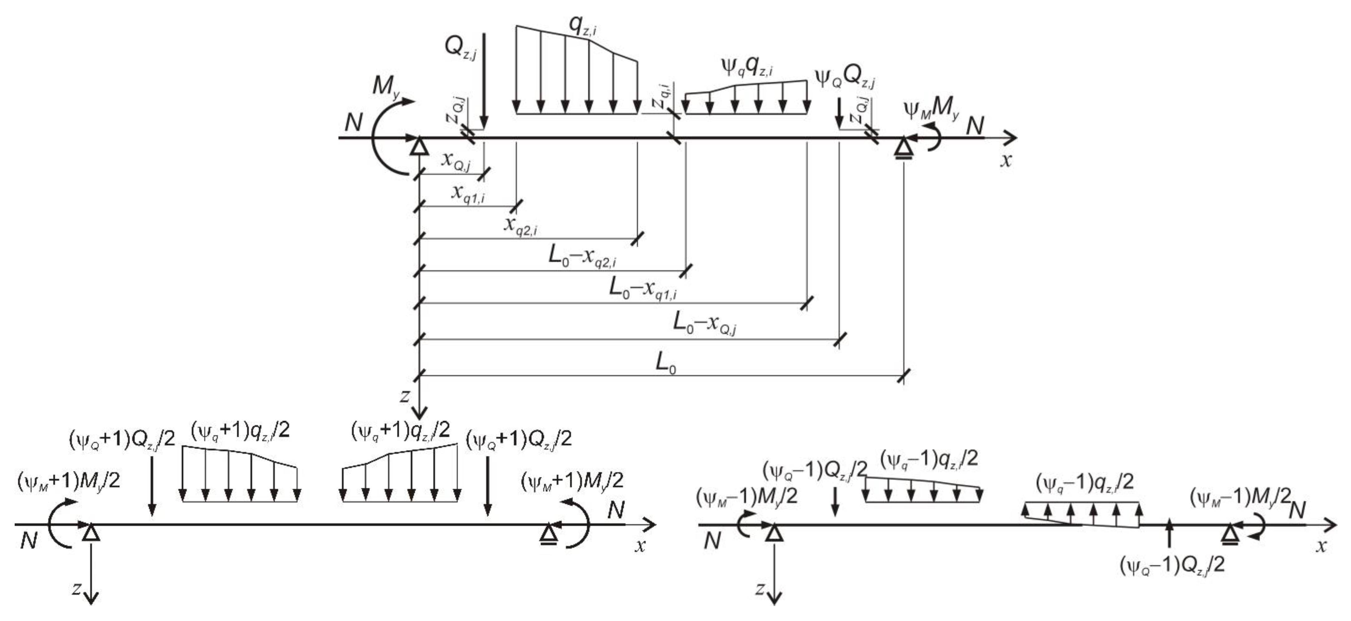
Using the principle of superposition, the in-plane moments are taken as the sum of symmetric M y , s I I and antisymmetric M y , a I I   moment components, corresponding to symmetric and antisymmetric load-components. In the proposed solution, the second-order in-plane moments M y , s I I and M y , a I I   are approximated by amplifying the symmetric and antisymmetric first-order in-plane moment components, M y , s I and M y , a I , respectively. In a similar way, the second-order moments M z , s I I and M z , a I I   are approximated by amplifying the symmetric and antisymmetric first-order out-of-plane moment components, M z , s I = M y , s I θ x and M z , a I = M y , a I θ x , respectively. Hence, the moment term in Equation (42) becomes
k 1 M y , s I θ x 1 N N y + M y , a I θ x 1 N N y a 2 v 0 M z E I z = k 1 E I z M y , s I θ x 1 N N y + M y , a I θ x 1 N N y a M y , s I θ x 1 N N z + M y , a I θ x 1 N N z a ,
where N y , N y a are two lowest bifurcation forces about the y axis, corresponding to symmetric and antisymmetric buckling-modes.
Substituting Equation (44) into Equation (42), the buckling problem converts to a nonlinear-eigenproblem analysis (NEA). For the shear-center loading system, the solution becomes
M y , m a x C b c , 0 M c r , 0 2 = 1 N N y 1 N N z 1 N N T .
The equivalent uniform moment-modification-factor takes the form
C b c , 0 = k 1 M y , s , max M y , max   1 C b s , r e m 2 + 1 N N y 1 N N z 1 N N y a 1 N N z a   M y , a , max M y , max     1 C b a , r e m 2 0.5
where 1 C b s , r e m 2 = 2 0 1 M y , s ξ M y , s , m a x 2 sin 2 π ξ d ξ , 1 C b a , r e m 2 = 2 0 1 M y , a ξ M y , a , m a x 2 sin 2 π ξ d ξ are reciprocals squared of the refined-energy-method conversion-factors.
One may notice that for laterally and torsionally unrestrained members, for which N z N y , the following relationships hold:
1 N N y = 1 1 k 1 N N z ,
1 N N y a = 1 1 k 1 N N z a .
For all the other solutions in which the applied loads are the off-shear center loads, the factor C b c , 0 is to be replaced by C b c , where the latter is related to the former as
C b c = C b c , 0 ζ .
The parameter ζ , representing the effect of off-shear span load F z , distributed q z and/or concentrated Q z , applied at a distance z F from the shear centre, z q or z Q , respectively, takes the form
ζ = 1 + C b F z F i 0 2 N T 1 N N T .
In Equation (50), the off-shear load-dependent factor C b F z F is calculated as follows:
C b F z F = { 2 L 2 π 2 i [ ξ q 1 , i ξ q 2 , i ( 1 + ψ q , i ) q z , i z q , i 2 sin 2 ( π ξ ) d ξ + 1 ξ q 2 , i 1 ξ q 1 , i ( 1 ψ q , i ) q z , i z q , i 2 sin 2 ( π ξ ) d ξ ] for   distributed   loads , 2 L π 2 j { ( 1 + ψ Q , j ) Q z , j z Q , j 2 sin 2 ( π ξ j ) + ( 1 ψ Q , j ) Q z , j z Q , j 2 sin 2 [ π ( 1 ξ j ) ] } for   concentrated   loads .
The coefficient C b F , representing the effect of off-shear span loads on the FTB state is not dependent upon the formulation of the strain-energy equation.
Table 1 presents a summary of these coefficients and the equivalent uniform moment-modification-factors developed for the classical energy-method C b s , c e m and C b a , c e m as well as C b s , r e m and C b a , r e m , based on refined versions of the classical energy-method. This refinement is based on the inclusion of an additional term, M z / E I z , in the strain-energy definition; cf. Equation (42).
One may notice that the moment conversion-factors C b s , c e m and C b a , c e m are generally greater than those of C b s , r e m and C b a , r e m , especially for the antisymmetric component of asymmetric-loading systems. Equation (8) with the factors C b s = C b s , r e m and C b a = C b a , r e m are used hereafter as a generalized Cuk–Trahair solution [10] for asymmetric-loading systems other than those with unequal end-moments.

5. Verification of Results

The developed analytical solution, based on the refined energy-equation, seems to be a generalization of that developed by Mohri et al. [20] for the symmetric-loading systems. In order to prove this, the scope of this verification exercise covers two selected loading cases from those presented in Table 1. The first one is concerned with a shear-center uniformly distributed load over the entire length of the member (Case 1: i = 1 and ψ q , i = 1 ) and the second one deals with a concentrated load applied at the shear center one quarter of the beam-column length from both supports (Case 2: j = 1 and ψ Q , j = 1 ). The results are presented in Figure 4 and Figure 5 for two hot-rolled steel beam-columns with sections IPE 180 (Figure 4a and Figure 5a) and HEB 180 (Figure 4b and Figure 5b), both of length 6 m. The verification allows for the illustration of a buckling-state dependence upon the section type and the effect of prebuckling deflections.
The results obtained from the analytical solutions (solid black line of the present study of the refined energy-method and Mohri et al. [20] (for symmetric loads), solid red line of the classical energy-method [13] and blue for the generalized Cuk–Trahair solution [10]), are compared with those of the finite-element software (circles from LTBeamN [21] and squares from PRFELB [12]).
The solution of the present study is valid for the in-plane loading systems that are not necessarily symmetric, in reference to the member mid-length cross-section. Since the greatest difference between the LEA equivalent uniform moment-modification-factors and those from NEA of the present study are identified for asymmetric-loading systems, the antisymmetric in-plane loading systems are of concern for the verification. The same member length as well as the loading and section types are concerned. A shear-center uniformly distributed load over the half length of the member (Case 3: i = 1 but ψ q , i = 1 ) and a concentrated load applied at the shear center one quarter of the beam-length from both supports (Case 4: j = 1 but ψ Q , j = 1 ) are dealt with. The results are presented in Figure 6 and Figure 7, respectively.

6. Discussion of Results

The results presented in the previous section, reinforced by their verification with results obtained from the analytical solution of Mohri et al. [
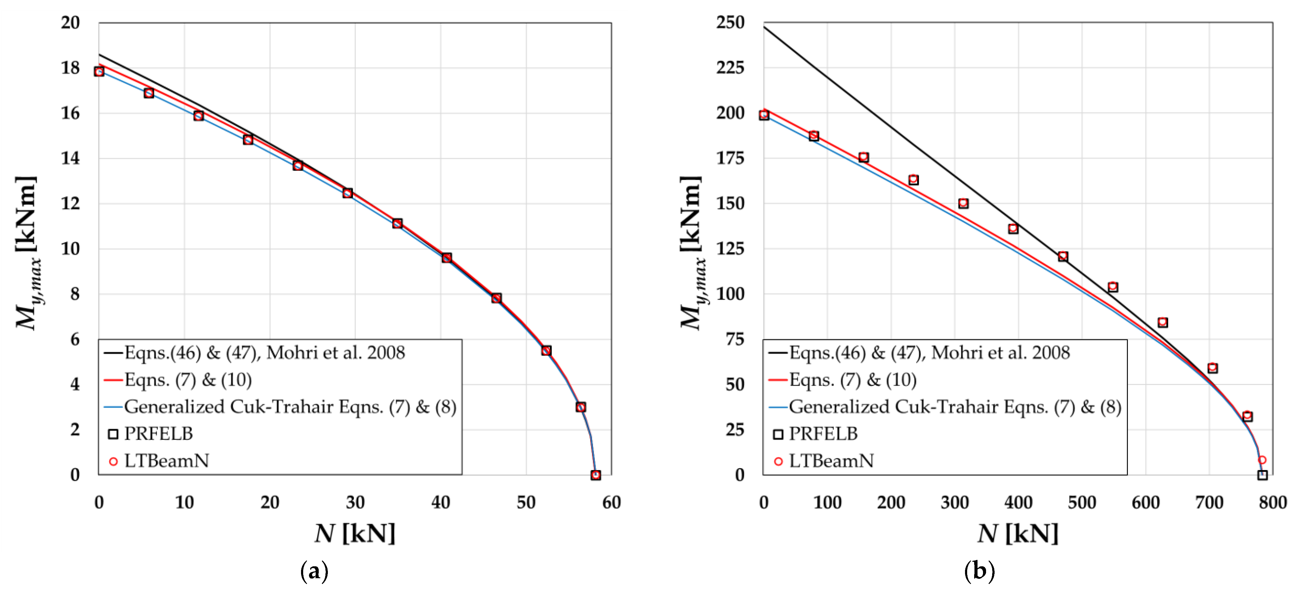
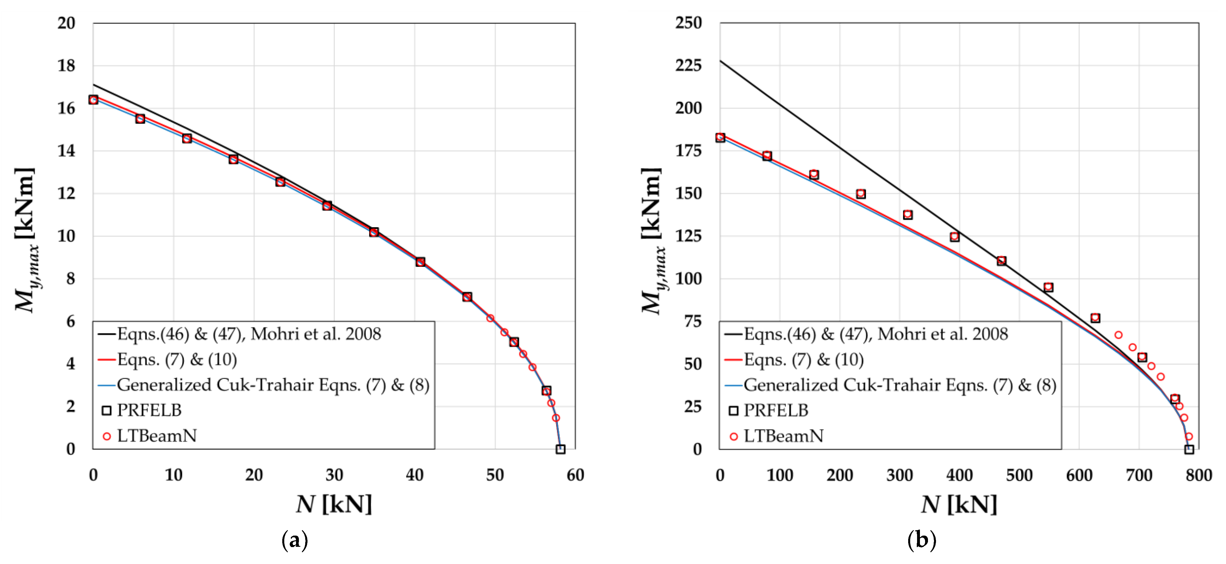
20] and from the computer programs LTBeamN and PRFELB show that for the considered symmetric-loading systems and for the steel section of IPE 180:
1. Results from the analytical models of the present study coincide with those of the analytical solution of Mohri et al. [20]. Moreover, they are verified positively by the finite-element results from both computer programs, LTBeamN and PRFELB.
2. The section exhibits a low value of k 1 , which means the out-of-plane instability appears at relatively small prebuckling deflections. Therefore, the prebuckling deflections do not play an important role in the attainment of the LTB state. As a consequence, the problem of critical-moment assessment for the symmetric-loading cases may follow LEA, for which k1 is not included in the classical LEA-based formulations of the buckling criterion.
3. The computer programs considered herein are based on LEA; therefore, they give results slightly lower than those from the present study and from Mohri et al. [20].
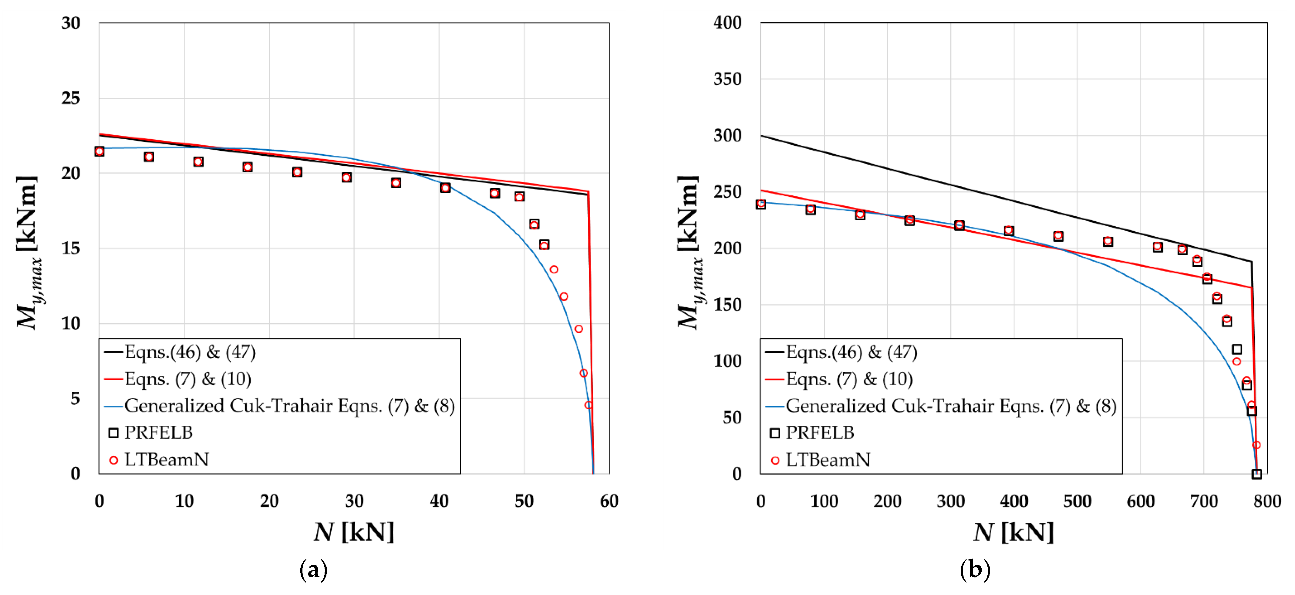
On the other hand, for the considered symmetric-loading systems and for the steel section of HEB 180, the following is observed:
1. Results of the present study coincide with those of Mohri et al. [20], since both include the effect of prebuckling deflections on the critical-state assessment.
2. The section exhibits a distinctively higher value of k 1 than that of IPE 180, which means the out-of-plane instability appears for larger prebuckling deflections. Therefore, the prebuckling deflections play an important role in the attainment of the LTB state. As a consequence, the critical moment for the symmetric-loading cases evaluated by LEA is much lower than that calculated with the inclusion of both prebuckling stress-resultants and the prebuckling deflected profile in the analytical formulation of the buckling criterion.
3. The computer programs LTBeamN and PRFELB give results that do not coincide with those from the analytical solutions of the present study and from Mohri et al. [20]. The results of the maximum-moment and the axial-compressive force at the buckling state, evaluated from the computer simulation, are well below those from the analytical models.
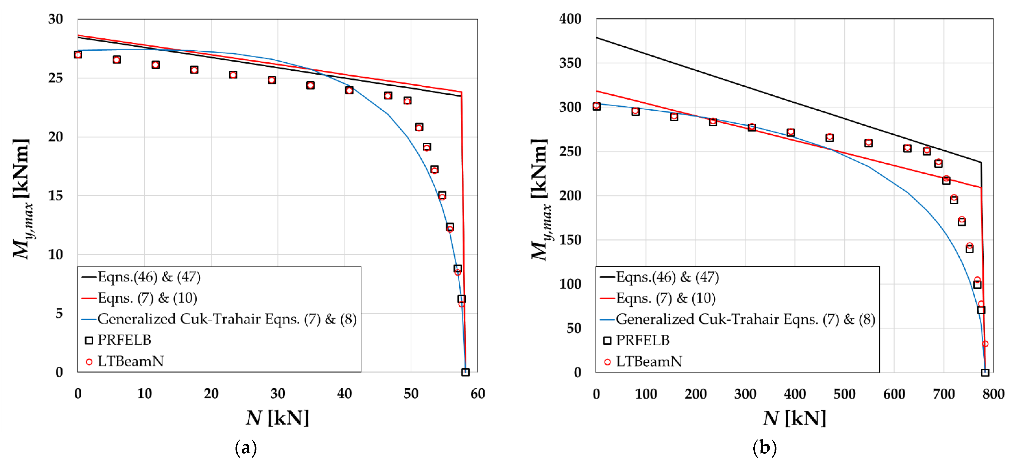
The other observations and discussions may be formulated on the basis of the results obtained for the asymmetric-loading systems. To the best of the authors’ knowledge, results for such loading cases have not yet been reported in the subject literature. Based on the results presented in this paper for the antisymmetric-loading cases, the following observations may be presented:
1. Results based on the LEA solution of Giżejowski et al. [13] and of the present study constitute for antisymmetric-loading systems the bi-line curves. This indicates that the analytical models reflect a rather weaker interaction between the LTB mode in bending and the lowest buckling modes in compression than is indicated by the results of the computer simulations.
2. The LEA analytical solution presented in Giżejowski et al. [13] and that of the present study give the results constituting the upper bound for the computer results; all of the results become rather comparable for such a loading asymmetry, in which the loads of both half-lengths of the beam-column are being described by positive values of ψi.
3. The finite-element results from both the computer programs LTBeamN and PRFELB are identical or close to each other, but placed well below those from the present study analytical model that includes the effect of the prebuckling deflected-profile on the buckling load.
4. The general analytical solution derived in the present study and valid for any asymmetric in-plane loading system may be suggested for practical applications when the load asymmetry factor is positive. The solution presented needs an introduction of a semi-analytical buckling-modes interaction factor calibrated with the use of the results obtained from finite-element simulations and carried out with the use of the LTBeamN and PRFELB programs.

7. Concluding Remarks

In the design of steel beam-columns, the basic condition associated with the verification is the member buckling-resistance check. Modern design codes, cf. Simoes da Silva et al. [22], introduce the so-called general method (GM) for the verification of a multiple-stress-resultant buckling state. In such methods, the prebuckling-inelastic solutions are connected with the elastic-buckling solutions in the same way as for the design procedures valid for a single stress-resultant, i.e., for compression or major-axis bending. For details, the reader is directed to the paper by Gizejowski et al. [23]. The present paper is devoted to the derivation of a general solution for the prediction of the elastic-buckling response of bisymmetric open-section beam-columns under compression and major-axis bending.
In formulating an elastic-buckling model, different analytical approaches may be used. The derivation in this paper was performed in a different way than is usually presented and discussed in the subject literature. It was based on the small-rotation matrix formulated in the member deflected-configuration and used straightforwardly for the description of the displacement-field and nonzero strain-components. A non-classical energy equation, with key refinements to the classical one was derived and discussed. It is used for the development of a general solution for the elastic FTB of beam-columns subjected to any asymmetric in-plane loading system.
The proposed analytical solution was verified with the use of the other analytical solutions existing in the literature, and also using results of numerical finite-element simulations based on the Vlasov theory of thin-walled members. The results were widely discussed and summarized, which allows for a conclusion that the analytical general solution developed in this paper may be postulated for use in GM as a modern tool for steelwork design, provided that the load-asymmetry factor in the two beam-column half-lengths is characterized by a positive value of ψi.
Further investigations are underway in order to calibrate a semi-analytical buckling-modes interaction factor for use in the antisymmetric-loading-system component of the applied asymmetric-load-pattern.

Author Contributions

Conceptualization, A.M.B. and M.A.G.; methodology, A.M.B. and M.A.G.; software, J.P.P.; verification, A.M.B. and M.A.G.; formal analysis, A.M.B. and J.P.P.; investigation A.M.B., M.A.G. and J.P.P.; resources, A.M.B., M.A.G. and J.P.P.; data curation, A.M.B., M.A.G. and J.P.P.; writing—original draft preparation, A.M.B. and M.A.G.; writing—review and editing, J.P.P.; visualization, A.M.B.; supervision, M.A.G. and J.P.P.; project administration, not applicable; funding acquisition, not applicable. All authors have read and agreed to the published version of the manuscript.

Funding

This research received no external funding.

Data Availability Statement

Data Sharing not applicable.

Conflicts of Interest

The authors declare no conflict of interest.

References

  1. Timoshenko, S.P.; Gere, J.M. Theory of Elastic Stability, 2nd ed.; McGraw-Hill: New York, NY, USA, 1961. [Google Scholar]
  2. Vlasov, V.Z. Thin-Walled Elastic Beams, 2nd ed.; Israel Program for Scientific Translation: Jerusalem, Israel, 1961; 493p. [Google Scholar]
  3. Chen, W.F.; Atsuta, T. Theory of Beam-Columns, Vol. 1: In-Plane Behavior and Design, 1st ed.; McGraw-Hill: New York, NY, USA, 1976; 513p. [Google Scholar]
  4. Chen, W.F.; Atsuta, T. Theory of Beam-Columns, Vol. 2: Space Behavior and Design; McGraw-Hill: New York, NY, USA, 1977; 732p. [Google Scholar]
  5. Trahar, N.S. Flexural–Torsional Buckling of Structures, 1st ed.; CRC Press: Boca Raton, FL, USA, 1993; 388p. [Google Scholar]
  6. Yang, Y.B.; Kuo, S.R. Theory and Analysis of Nonlinear Framed Structures, 1st ed.; Prentice Hall: Singapore, 1994; 450p. [Google Scholar]
  7. Trahair, N.S.; Bradford, M.A.; Nethercot, D.A.; Gardner, L. The Behaviour and Design of Steel Structures to EC3, 4th ed.; Taylor & Francis: London, UK, 2008; 512p. [Google Scholar]
  8. Kindmann, R.; Kraus, M. Steel Structures. Design Using FEM, 1st ed.; Wilhelm Ernst & Sohn: Berlin, Germany, 2011; 552p. [Google Scholar]
  9. Pi, Y.L.; Trahair, N.S.; Rajasekaran, S. Energy equation for beam lateral buckling. J. Struct. Eng. 1992, 118, 1462–1479. [Google Scholar] [CrossRef]
  10. Cuk, P.E.; Trahair, N.S. Elastic buckling of beam-columns with unequal end moments. Civ. Eng. Trans. 1981, 23, 166–171. [Google Scholar]
  11. Serna, M.A.; Lopez, A.; Puente, I.; Yong, D.J. Equivalent uniform moment factors for lateral–torsional buckling of steel members. J. Constr. Steel Res. 2006, 62, 566–580. [Google Scholar] [CrossRef]
  12. Papangelis, J.P.; Trahair, N.S.; Hancock, G.J. Elastic flexural-torsional buckling of structures by computer. Comput. Struct. 1998, 68, 125–137. [Google Scholar] [CrossRef]
  13. Giżejowski, M.A.; Barszcz, A.M.; Stachura, Z. Elastic flexural-torsional buckling of steel I-section members unrestrained between end supports. Arch. Civ. Eng. 2021, 67, 635–656. [Google Scholar]
  14. Bradford, M.A.; Cuk, P.E.; Gizejowski, M.A.; Trahair, N.S. Inelastic lateral buckling of beam-columns. J. Struct. Eng. 1987, 113, 2259–2277. [Google Scholar] [CrossRef]
  15. Pi, Y.L.; Trahair, N.S. Nonlinear inelastic analysis of steel beam-columns. Part I: Theory. J. Struct. Eng. 1994, 120, 2041–2061. [Google Scholar] [CrossRef]
  16. Pi, Y.L.; Trahair, N.S. Nonlinear inelastic analysis of steel beam-columns. Part II: Applications. J. Struct. Eng. 1994, 120, 2062–2085. [Google Scholar] [CrossRef]
  17. Pi, Y.L.; Bradford, M.A. Effects of approximations in analyses of beams of open thin-walled cross-section—Part I: Flexural–torsional stability. Int. J. Numer. Methods Eng. 2001, 51, 757–772. [Google Scholar] [CrossRef]
  18. Pi, Y.L.; Bradford, M.A. Effects of approximations in analyses of beams of open thin-walled cross-section—Part II: 3-D nonlinear behaviour. Int. J. Numer. Methods Eng. 2001, 51, 773–790. [Google Scholar] [CrossRef]
  19. Barszcz, A.M.; Giżejowski, M.A.; Pękacka, M. Elastic lateral-torsional buckling of bisymmetric double-tee section beams. Arch. Civ. Eng. 2022, 68, 83–103. [Google Scholar]
  20. Mohri, F.; Bouzerira, C.; Potier-Ferry, M. Lateral buckling of thin-walled beam-column elements under combined axial and bending loads. Thin-Walled Struct. 2008, 46, 290–302. [Google Scholar] [CrossRef]
  21. LTBeamN Software, Vesion 1.0.4, CTICM. Available online: https://www.cticm.com/logiciel/ltbeamn/ (accessed on 1 January 2022).
  22. Simoes da Silva, L.; Simoes, R.; Gervasio, H. Design of Steel Structures. Eurocode 3: Design Steel Structures, Part 1-1—General Rules and Rules for Buildings, 2nd ed.; Wilhelm Ernst & Sohn: Berlin, Germany, 2016; 456p. [Google Scholar]
  23. Gizejowski, M.A.; Stachura, Z.; Szczerba, R.B.; Gajewski, M.D. Out-of-plane buckling resistance of rolled steel H-section beam-columns under unequal end moments. J. Constr. Steel Res. 2019, 160, 153–168. [Google Scholar] [CrossRef]
Figure 1. Member’s elementary-length kinematics in reference to the first-order rotation matrix.
Buildings 13 00307 g001
Figure 2. Fiber kinematics.
Buildings 13 00307 g002
Figure 3. In-plane loading system considered, and its decomposition into symmetric and antisymmetric components.
Buildings 13 00307 g003
Figure 4. Verification of results from the present study with those of Mohri et al. [20] and computer programs LTBeamN and PRFELB for Case 1 of the in-plane loading system: (a) beam-column of section IPE 180; (b) beam-column of section HEB 180.
Buildings 13 00307 g004
Figure 5. Verification of results from the present study with those of Mohri et al. [20] and from computer programs LTBeamN and PRFELB for Case 2 of the in-plane loading system: (a) beam-column of section IPE 180; (b) beam-column of section HEB 180.
Buildings 13 00307 g005
Figure 6. Verification of results from the present study with those from computer programs LTBeamN and PRFELB for Case 3 of the in-plane loading system: (a) beam-column of section IPE 180; (b) beam-column of section HEB 180.
Buildings 13 00307 g006
Figure 7. Verification of results from the present study with those from computer programs LTBeamN and PRFELB for Case 4 of the in-plane loading system: (a) beam-column of section IPE 180; (b) beam-column of section HEB 180.
Buildings 13 00307 g007
Table 1. Equivalent uniform moment-modification-factors for non-uniform bending under symmetric and antisymmetric components of asymmetric-loading systems.
Loading System C b s , c e m C b s , r e m C b a , c e m C b a , r e m C b F
Concentrated moments * Buildings 13 00307 i001112.782.77-
Uniformly distributed loads ** Buildings 13 00307 i0021.151.131.431.37qzL2/π2
Concentrated   load   at   L 0 / 2 Buildings 13 00307 i0031.421.37--2QzL/π2
Concentrated   loads   at   3 L 0 / 8
 from the supports **
1.171.141.761.493.414QzL/π2
Concentrated   loads   at   L 0 / 3
 from the supports **
1.121.101.741.563QzL/π2
Concentrated   loads   at   L 0 / 4
 from the supports **
1.051.041.811.732QzL/π2
Concentrated   loads   at   L 0 / 6
 from the supports **
1.011.012.011.98QzL/π2
Concentrated   loads   at   L 0 / 8
 from the supports **
1.011.012.152.140.586QzL/π2
* Unequal at supports; ** Unequal in half-lengths.
Disclaimer/Publisher’s Note: The statements, opinions and data contained in all publications are solely those of the individual author(s) and contributor(s) and not of MDPI and/or the editor(s). MDPI and/or the editor(s) disclaim responsibility for any injury to people or property resulting from any ideas, methods, instructions or products referred to in the content.

