Article

Parametric Study on Built-Up Cold-Formed Steel Beams with Web Openings Connected by Spot Welding

by
Antonio Andrei Cristian
1 and
Viorel Ungureanu
2,3,*
1
Department of Metal Constructions, Management and Engineering Graphics, Technical University of Civil Engineering Bucharest, 020396 Bucharest, Romania
2
Department of Steel Structures and Structural Mechanics, Politehnica University of Timisoara, 300224 Timisoara, Romania
3
Laboratory of Steel Structures, Romanian Academy, Timisoara Branch, 300223 Timisoara, Romania
*
Author to whom correspondence should be addressed.
Buildings 2023, 13(1), 237; https://doi.org/10.3390/buildings13010237
Submission received: 27 November 2022 / Revised: 6 January 2023 / Accepted: 11 January 2023 / Published: 14 January 2023
(This article belongs to the Special Issue Advances in the Behaviour of Steel Structures)

Abstract

:
This paper presents a numerical parametric study on cold-formed steel built-up beams subjected to bending. The cold-formed steel built-up elements are efficient structural elements that are easy to assemble during the construction process, ensuring material savings and potential for standardization, thus making them more suitable for mass production. A new technological solution for built-up steel beams with webs made of corrugated steel sheets and flanges made of cold-formed steel profiles, assembled through two welding techniques, was proposed within the well-formed research project. This solution can be used as a component of single or low-rise multi-story frames, purlins, or secondary beams. The experimental program investigated seven full-scale beams, two of which have web openings. The web openings were introduced for the case when these members are used as secondary beams in floor systems. The paper investigates these types of beams with web openings using parametric numerical analyses. A numerical model validated against experimental tests was proposed to carry out a parametric study through nonlinear finite element analysis, considering initial imperfections and considering the strain-hardening characteristics of the steel components. The influence of different components was analyzed through the parametric study. Beams with three lengths were studied, i.e., (1) 6000 mm, (2) 7500 mm, and (3) 9000 mm. In total, 61 simulations were found. The article highlights the parameters that contribute significantly to the stiffness and capacity of the built-up cold-formed steel elements. The weakest component was concluded to be the thickness of the corrugated web, while the presence of the stiffened web opening reduced the bearing capacity by approximately 5–10%.

1. Introduction

Lately, there has been a growing interest in using beams with corrugated webs, mainly because of their high shear resistances, even without additional stiffeners and the possibility of optimizing the welding process and reducing material and manufacturing costs. A summary of the research and development of girders with corrugated webs is presented in Elgaaly and Dagher [1]. Luo and Edlund [2] performed finite element (FE) simulations to perform a parametric study on corrugated web girders. They found that the ultimate shear capacity increases proportionally with the depth of the girder, but it seems that it is not dependent on the girder-length-to-depth ratio. However, the post-buckling shear capacity not only increases with the girded web but also depends on the ratio between the girder-length-to-depth ratio. They found that the depth of the corrugation does not significantly affect the ultimate shear capacity but affects the localization degree of the buckling mode.
Elgaaly et al. [3] observed that the contribution of the corrugated web to the ultimate bending moment capacity can be neglected depending on the flange yield stress. Johnson and Cafolla [4] studied the beams numerically and experimentally with corrugated webs and also concluded that the web contributed insignificantly to the flexural capacity of the elements.
Chan et al. [5] used FE simulations to investigate the behavior of beams with corrugated webs under the bending moment. They found that vertically corrugated webs provide a stiffer support against flange buckling than horizontally corrugated webs and flat webs. Lindner [6] investigated the lateral–torsional behavior of steel girders with corrugated webs. He found that the torsional constant of the IT section does not differ from that of a beam with flat web, but the warping constant IW of the section is different. The effect of corrugations on the lateral–torsional buckling strength of the I-girders was studied by Pasternak [7] who presented a proposal for Annex D of EN 1993-1-5:2006 [8].
Luo and Edlund [9] performed nonlinear FE simulations considering four factors which influence the buckling strength of the beams, i.e., (1) the strain-hardening model, (2) the corner effect, (3) the initial imperfections, and (4) the loading position. They used the Ramberg–Osgood strain-hardening model for the webs and obtained the ultimate strength of the girders which was 8–12% higher than those obtained using an elastic–perfect plastic model.
Kövesdi et al. [10] experimentally studied the stress distributions in the flanges of girders with corrugated webs. They concluded that a beam with corrugated web behaves similarly to a lattice girder where the bending moment is carried out by flanges and the transverse forces are transferred through the diagonals and vertical elements.
Cold-formed steel structures recorded significant advances over the past few years and facilitated the construction of lightweight and complex structures. With a high protection against corrosion, with all components galvanized, these have a major advantage compared to traditional steel structures. There is growing interest in expanding the applications of cold-formed steel to larger structures. Hence, extensive research is conducted in the field of built-up cold-formed elements assembled with bolts, screws, laser welding, or spot welding.
In another research project, Zhao [11] proposed the investigation of hollow flange beams (HFBs) and rectangular hollow flange beams (RHFBs) assembled using spot welds, screw fasteners, and self-pierced rivets. This investigation focused on the behavior of members under axial compression. He found that the types of fastening and spacing do not significantly affect the compression capacity of the members. Wanniarachchi [12] further developed the investigations of Zhao [11] and developed a cold-formed steel beam with rectangular hollow flanges (RHBFs) assembled using intermittent screw fastening. He found that this assembly solution is structurally sound and minimizes te fabrication costs.
Smith [13] studied the behavior of girders with corrugated webs connected through the flanges using intermittent welds. He found that the connection between the flanges and the web is critical to shear strength and that the weld is subjected to high stresses. He concluded that intermittent welds should be avoided.
Landolfo et al. [14] investigated a structural solution, known as the modular light-weight cold-formed (MLC) beam [15]. The solution was designed to be used as the main frame for multi-story buildings located in seismic areas. The section of the MLC beam is composed of two special back-to-back C-profiles, with reinforcing steel plates placed inside the hollow flanges and assembled by laser welding. The joining technology was chosen with the aim of reducing manufacturing costs and production times.
Kanthasamy et al. [16] performed a set of numerical analyses to examine the bending behavior of built-up sections composed of three types of cross-sections, i.e., super-sigma, folded-flange, and optimized-LCB, with three different materials. For structural applications, they recommended the use of folded-flange built-up sections to take advantage of both capacity and stiffness.
A new technological solution that combines both the advantages of beams with corrugated web and cold-formed steel elements was developed within the well-formed research project [17,18,19]. The connection between the components of the beam was made by spot welding, a technique that reduces the workmanship and cost of joining technology.
The beams with web openings represent a practical solution when ducting systems need to be accommodated and they are also commonly used for multi-story buildings. Extensive research was performed on beams with web openings, including beams with corrugated webs and web openings. Romeijn [20] conducted a numerical parametric study on girders with cut-out corrugated web. The investigations showed that in a girder with a corrugated web, an increase in the height of the girder leads to a decrease in the shear resistance. The authors recommended that numerical research should be followed by experimental research.
Al-Dafafea [21] experimentally studied the behavior of beams with rigidly rolled large openings. The authors concluded that the horizontal stiffeners are the best stiffening solutions. Double- or single-sided stiffeners also significantly improve the ultimate carrying capacity of beams.
New steel sections such as the dog-bone-shaped cross-section have a higher resistance to lateral–torsional buckling [22] and were tested to highlight the parameters that influence the resistance of elements with web openings.
High-strength steel elements may have a different behavior when the web openings are cut. The tests carried out on 12 specimens of H-sections, made of high-strength steel with a different ratio of web depth to flange width, a different ratio of flange width to thickness, a different ratio of web depth to thickness, a different ratio of hole diameter to web depth, and a number of holes in the web, subjected to flexural behavior, showed that the number of holes and diameters is insignificant for the elastic stiffness, flexural strength, and ductility under gradient bending moments, but they deteriorate for constant bending moments [23]. The results were sustained by the numerical analysis performed in [24].
Meng et al. [25] proposed a new type of reinforced connection with good anti-collapse performance. This connection is characterized by M-shaped structural plates arranged inside the upper and lower flanges of the beam end based on the connection with the openings in the beam web. The addition of M-shaped structural plates contributes to an improvement in the initial stiffness, yield load, yield, and displacement, as well as the ultimate load of the structure under cyclic loading.
Lite steel beams (LSBs) with web openings [26] were investigated under bending moments. There is significant interest in the use of LSB sections as flexural members in floor joist systems. The authors investigated the influence of the hole diameter and the degree of spacing on the plastic bending behavior of the LSB. They recommended a conservative design method based on the use of the section properties of LSB sections with continuous web holes to calculate the capacity. Mahendran and Keerthan [27] studied LSBs with stiffened web openings. They recommended suitable screw-fastened plate stiffener arrangements to keep the original shear capacity of the LSBs.
Acharya et al. [28] proposed several reinforcement solutions for cold-formed steel joists with a large web opening in the shear zone. Laboratory experiments included nine sets of shear capacity tests on cold-formed galvanized lipped channel sections (with a depth of 203 mm and a length of 1092 mm), with a large unreinforced and reinforced web opening located in shear zones. The effectiveness of the reinforcement solution depends on the reinforcement type and length, as well as on the screw spacing and pattern.
Based on a numerical study, Wang and Young [29] obtained a modified version of the direct strength method formulae to evaluate the moment capacities of the built-up cold-formed steel open and closed section beams with holes. For similar elements, Yu et al. [30] proposed a method to determine the elastic critical buckling stress and the moment of distortional buckling.
An opening in the web also affects the deflection of a beam subjected to bending. Additional deflections for cold-formed steel C sections were analytically studied based on experimental results from Mark Lawson and Basta’s study [31]. The application of the formulas is limited by the span-to-height ratio and the opening height-to-section height ratio.
Based on finite element models showing various buckling modes, Osgouei et al. proposed a set of analytical solutions for the local buckling of cold-formed steel webs with rectangular openings stiffened with intermediate and edge stiffeners [32].
Uzzaman et al. [33,34] experimentally and numerically studied lipped channel sections with and without circular web holes subjected to web crippling. An FE model containing nonlinear geometrical and material features was developed and calibrated using the experimental results. A parametric study was conducted using the calibrated FE model. The web crippling strength reduction factors equations were proposed. Later, using experimental tests and nonlinear finite element analyses, Uzzaman et al. [35] investigated the effect of edge-stiffened circular web holes on the web crippling strength of lipped channel sections under interior-two-flange loading conditions.
An analytical model used to compute the yield shear load of channel sections with square and circular holes has been formulated by [36] to predict the shear strength of elements subjected predominantly to shear with a shear span aspect ratio of 1. For the shear span ratio reaching up to 2, a model is presented in [37] and for openings of high-strength cold-formed channel sections with elongated holes in [38].
The transverse load-carrying capacity of sinusoidally corrugated steel web beams with openings was studied by Kiymaz et al. using the FEA [39]. They analyzed beams with and without web holes in terms of load deformation characteristics and ultimate web shear resistance. The resistance of beams without web openings was close to that predicted in Annex D of EC 1993-1-5 [8]. By introducing a web opening, the strength decreases between 15% and 50%.
Since web openings are commonly used in industry, the well-formed solution was further developed to accommodate a web opening [40,41], which gave rise to additional design considerations. Web openings were used in the case where these members are used as secondary beams in floor systems. In the first part, the paper presents the calibration and validation of numerical models based on previous experimental campaigns held within the well-formed research project [19,40]. In the second part, an extended parametric study was performed on built-up cold-formed steel beams with corrugated web assembled using spot welding to study the influence of each component and optimize the solution. Beams with three lengths were selected, i.e., (1) 6000 mm, (2) 7500 mm, and (3) 9000 mm, which were considered as usual dimensions for beams in multi-story buildings.

2. Summary of Experimental Investigations

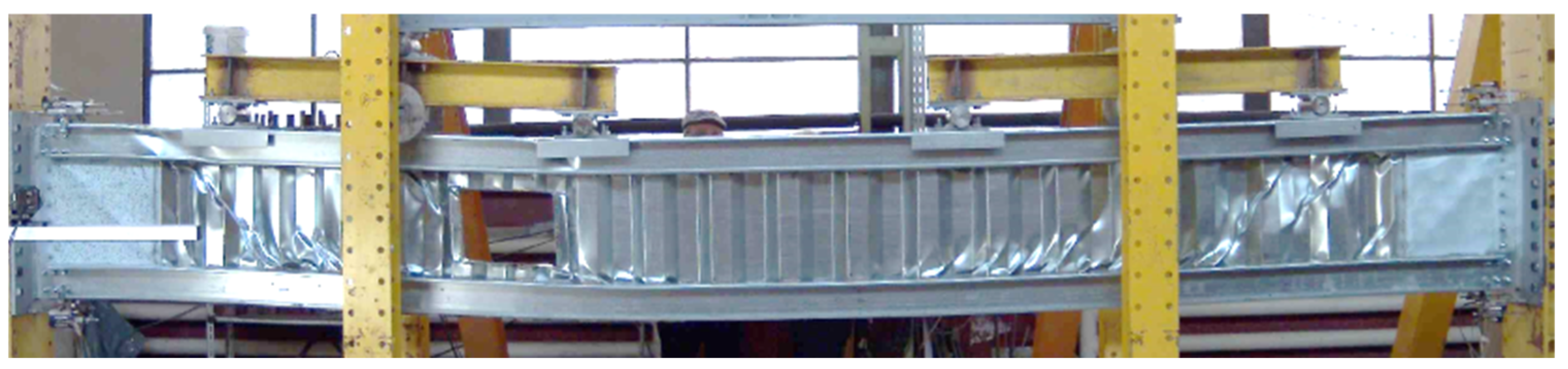
2.1. Validation Data

In the previously mentioned well-formed research project, the experimental campaign included tensile tests on samples extracted from the components of the built-up beam and tensile shear tests on the lap joint spot-welded specimens. Different combinations of steel sheets with various thicknesses were tested according to the provisions of EN1993-1-3 [42] and ISO 6892-1 [43].
A part of the experimental program investigated two full-scale beams with strengthening solutions for the openings of the web, according to the welding techniques used, i.e., (1) for the case of the resistance spot welding, a reinforcing plane steel sheet positioned in the web plane and welded to the corrugation of the web, and (2) for the case of metal inert gas (MIG) brazing, a plate perpendicular to the web plane as a border type frame on the opening perimeter. The experimental results are presented in [40] and highlight the capacity and deformation, as well as the failure evolution of the components.
Full-scale beam specimens were tested, with spans of 5157 mm, including connections to the experimental frame, and heights of 600 mm. Figure 1 shows the components of the built-up beam with corrugated web (CWB) and Figure 2 presents the configuration with web openings. The web opening has a height of 250 mm and a width of 310 mm. Figure 3 presents the reinforcements of the web opening, which is composed of flat steel plates with thicknesses of 2.0 mm. The standard configuration of the built-up beam consisted of the following components:
  • flanges of back-to-back lipped channels with a cross-section of C120/47/2.0;
  • corrugated webs made of steel sheets of 0.80 mm (mid part of the beam) and 1.20 mm (at beam ends);
  • shear panels at both ends of the beam (flat plates with thicknesses of 1.00 mm or 1.20 mm), where the shear force is the highest;
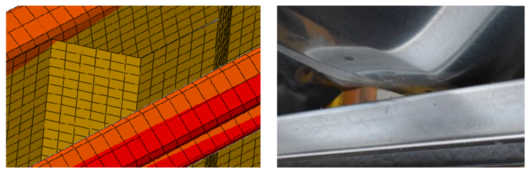
  • U150/70/2.0 as reinforcing profiles at the point-of-application of the forces in order to avoid excessive local deformations.

2.2. Experimental Results

The built-up beams were tested on a 2D rigid testing frame with both ends fixed to the frame and loaded by a 500 kN actuator through a leverage system that uniformly distributed the load in four points to simulate a uniform distributed load. A 2 mm/s displacement was applied to the actuator to simulate the quasi-static loading regime. The actuator load cell recorded the force, while the wire linear transducers were placed at each quarter of the span monitored by vertical displacements. Out-of-plane displacements and buckling were restricted by a separate structure in two locations. Details on the experimental testing of the CWB with web openings are presented in detail in [40].
The size of the web opening was considered a reasonable height to accommodate the service installations, while the length was limited by the distance between the corrugations, so that the spot welding could be applied, ensuring a minimum distance to the edge of the corrugation. For the specimen assembled by MIG brazing, the length of the opening was not limited by the distance between the corrugations, but it was chosen to be similar to the beam specimen assembled by spot welding. The position of the web opening was chosen in such a way to avoid the maximum stresses, i.e., the bending moment and shear force at the supports, and the bending moment at the middle of the beam.
The same welding techniques used for the CWB beams were also considered for the reinforcing solution to the opening of the web, as shown in Figure 4. For the beam assembled by spot welding (CWB-SW-WO), only one reinforcing steel plate (with a thickness of 2.0 mm) was welded on the opening contour, due to the limitation of welding another plate on the opposite side of the corrugation. Figure 1 presents the dimensions of the opening. The reinforcing plate was also bent at 90° on both sides parallel to the flanges. To strengthen the contour, these lips were also spot-welded to the flanges.
A better configuration for the web opening reinforcement was realized for the CWB specimen assembled by MIG brazing (CWB-CMT-WO). A steel plate (with a thickness of 1.2 mm) was bent to take the contour of the opening of the web. For the side parallel to the flanges, brazing was performed alternatively on each corrugation, while for the vertical sides, the brazing was applied as intermittent segments. Figure 5 presents the solution for reinforcing the opening of the web for the CWB specimen assembled by MIG brazing.
The response of the beam was not only evaluated by the bearing capacity, but also by the failure mechanism that led to the collapse. Figure 6 presents the deformed shape of the beam specimen assembled by spot welding. A significant deformation was observed on the left side of the web opening.
The deformations and failure sequence were recorded in the following order: (1) shear buckling of the shear panels, (2) deformations of the corrugated web in the corner of the opening, (3) distortions of the web corrugations close to the end of the beam, (4) shear buckling of the corrugations, (5) shear buckling of the corrugated web sheet (connecting the shear buckling of the corrugations), (6) failure of the spot welds after an increase in the previous deformations, and (7) buckling of the flanges under the load application point.
The second beam specimen, assembled using MIG brazing, also showed an increased deflection in the web opening side, but only in the last stage of the testing, as shown in Figure 7.
The degradation of the elastic response was initiated by a limited shear buckling of shear panels, which was less obvious than the shear buckling of the corrugation of the web. In the last stage, the increase in displacement caused the shear buckling of the corrugated web.
Since the samples tested were identical from the point of view of the configuration and thickness of the components, except the connection techniques and the reinforcement solution, the responses of the two beams could be compared. Higher rigidity was observed in the case of the MIG-brazed specimen, together with increased capacity and ductility (see Figure 8), due to the welding technology that restrains the corrugations against distortions.
The specimen assembled using spot welding allowed the corrugation to be distorted, reducing the initial rigidity, and the corrugation was then deformed in the early loading stages.
In the following, only corrugated web beams with web openings using spot welding technology were numerically investigated, mainly because the solution was prone to automation and mass production.

3. FE Model

The finite element program ABAQUS/CAE v.6.14 [44] was used to geometrically and materially perform nonlinear analysis with imperfections included (GMNIA). The numerical models include all the essential physical features of the tested specimens. The numerical models were validated through detailed comparisons in terms of stiffness, failure modes, plasticity spread, and buckling modes. For the model calibration, material and lap joint specimen tests were used. More complete descriptions of these features and modelling challenges are presented herein.

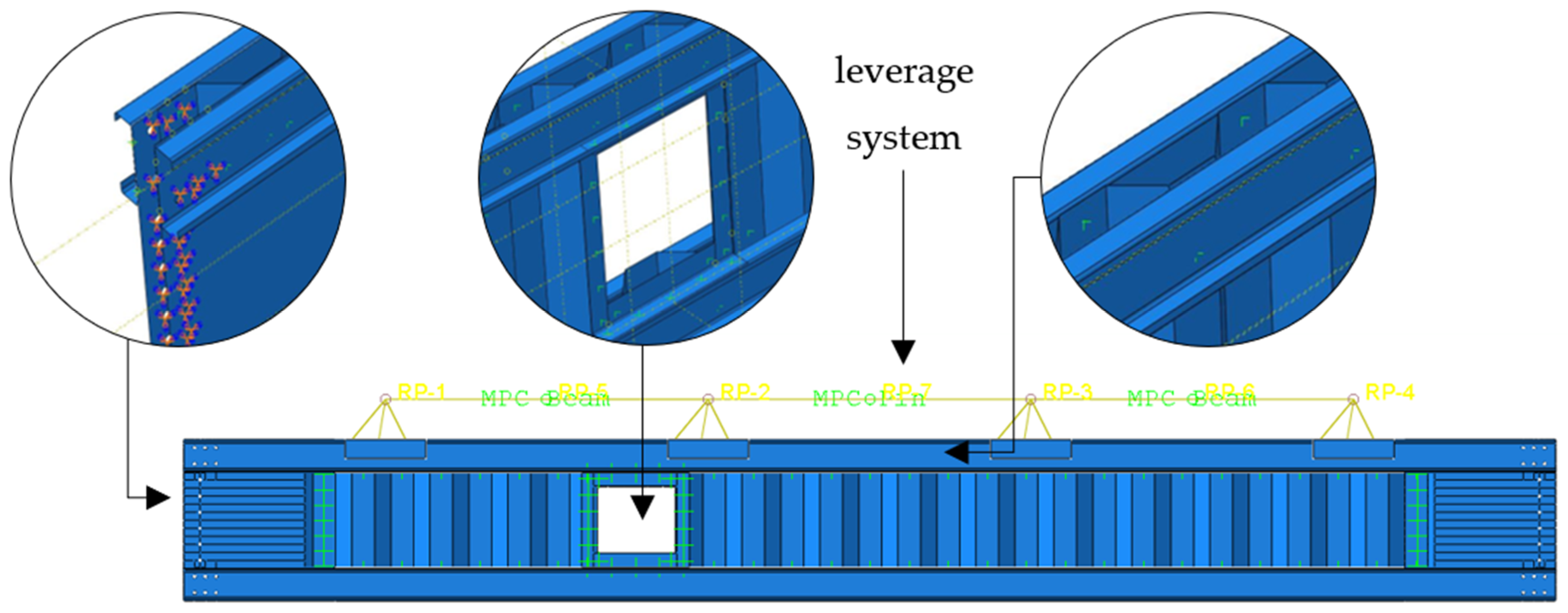
3.1. Supports Boundary Conditions

The numerical model must reproduce the essential features of the tested specimens without introducing a high degree of complexity in the model, which may lead to numerical/convergence issues. The modelling of the connections, contact areas, and load introduction points may often be problematic.
Connections are an important factor that influence the behavior of steel frames due to their ability to reduce the relative rotation between beams and columns. Since the study was focused only on beams, the M12 grade 8.8 bolts used for the beam ends connections in the experiments were considered in the simulations by blocking all degrees of freedom around the perimeter of the holes (see Figure 9). Numerical simulations considering only the degrees of freedom corresponding to the displacements blocked were also created, but they have been shown to have an insignificant influence on the results.
Further experimental tests and numerical simulations will be performed to fully characterize the behavior of the end connections.

3.2. Spot-Weld Modelling

The spot welds between the beam’s components were modelled using point-based fasteners with the connector response calibrated from the tensile shear tests. Attachment points were defined where spot welds are present (see Figure 9). The connectors were characterized by elasticity, plasticity, damage, and failure parameters. Bushing connector elements were used to model the spot welds. These elements provide a connection between two nodes that allows independent behavior in three local Cartesian directions that follow the system at both nodes, allowing different behavior in the two flexural rotations and one torsional rotation [44].

3.3. Geometrical Imperfections

The cold-formed steel elements are highly influenced by geometrical imperfections, in terms of strength, stiffness, and post-buckling behavior. Therefore, to replicate the structural response observed in the experiments, geometrical imperfections need to be characterized. The most straightforward approach to introduce geometrical imperfections is to use a global buckling analysis. However, this requires a large number of buckling modes in order to capture the stability solution.
A simplified approach was used, and geometrical imperfections were introduced as global vertical and lateral displacements through a static analysis. The deformed shape was later used in a dynamic explicit analysis which contained the geometric nonlinearities (see Figure 10). Nine cases of imperfection were considered and it was observed that an out-of-plane displacement of L/2500 and a vertical displacement of L/1500, where L is the length of the beam, can reproduce the mechanical response observed in the experiment.

3.4. Solver Scheme and Loading Setup

The numerical analysis consisted of two steps. The first step involved a static nonlinear analysis to introduce the geometrical imperfections. The second step involved a dynamic explicit analysis containing geometrical and material non-linearities (GMNIAs).
A vertical displacement was applied through a set of multipoint constraints (MPCs) that forms a leverage system (presented in Figure 9) which approximates with high accuracy and a uniformly distributed load. The leverage system distributes the displacement in four points, similar to the configuration of the tested beams. The link between the control points and the contact surfaces was defined by a kinematic coupling constraint for all the degrees of freedom. The control points were connected through RB3D2 elements, used as a rigid body in order to transfer the deflection.

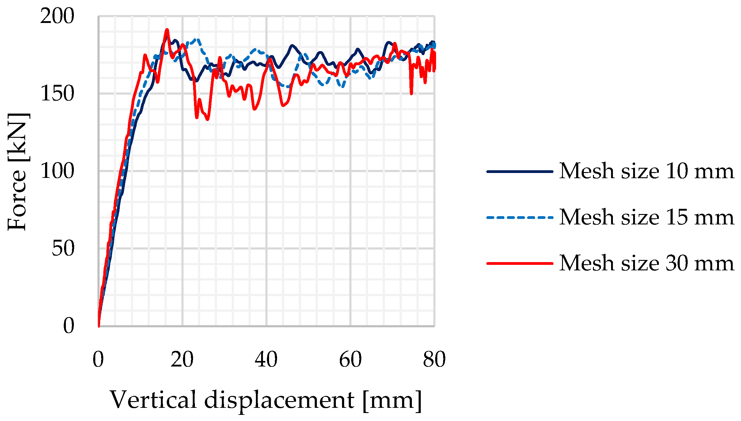
3.5. Element Selection and Mesh Sensitivity

In order to model the thin-walled components, the following elements were used: a rectangular four-node doubly curved thin or thick shell, reduced integration, hourglass control, and finite membrane strains (S4Rs), which are often found in the literature for modelling cold-formed steel profiles.
Considering the large number of simulations, the dimension of the finite elements was chosen considering the computational cost. To reduce the computational cost, a mesh sensitivity analysis was performed. Simulations with resolutions of elements equal to 10 mm, 15 mm, and 30 mm were carried out and the influence of the mesh size on the converged solution was studied.
Figure 11 presents the force–displacement curves for the three considered cases. It can be observed that the maximum force is similar in all three cases, but the force–displacement curve becomes smoother as the mesh size decreases. Figure 12 presents a comparison between von Misses stresses for the three cases considered and the experiment. For the parametric study, a 15 mm mesh size was used because it showed a good correlation between the numerical model and the experimental results, in terms of bearing capacity, but also instability phenomena and local failures.

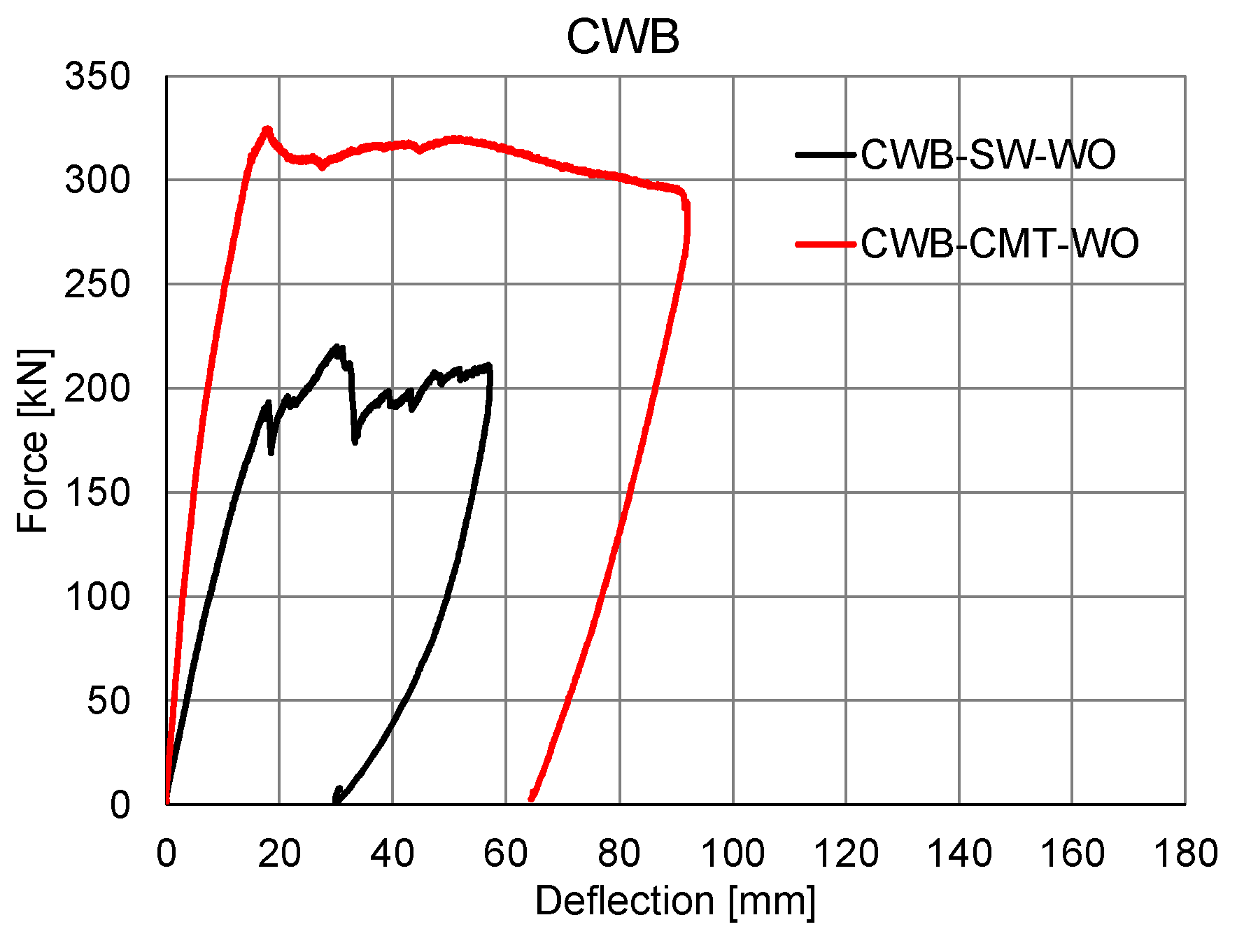
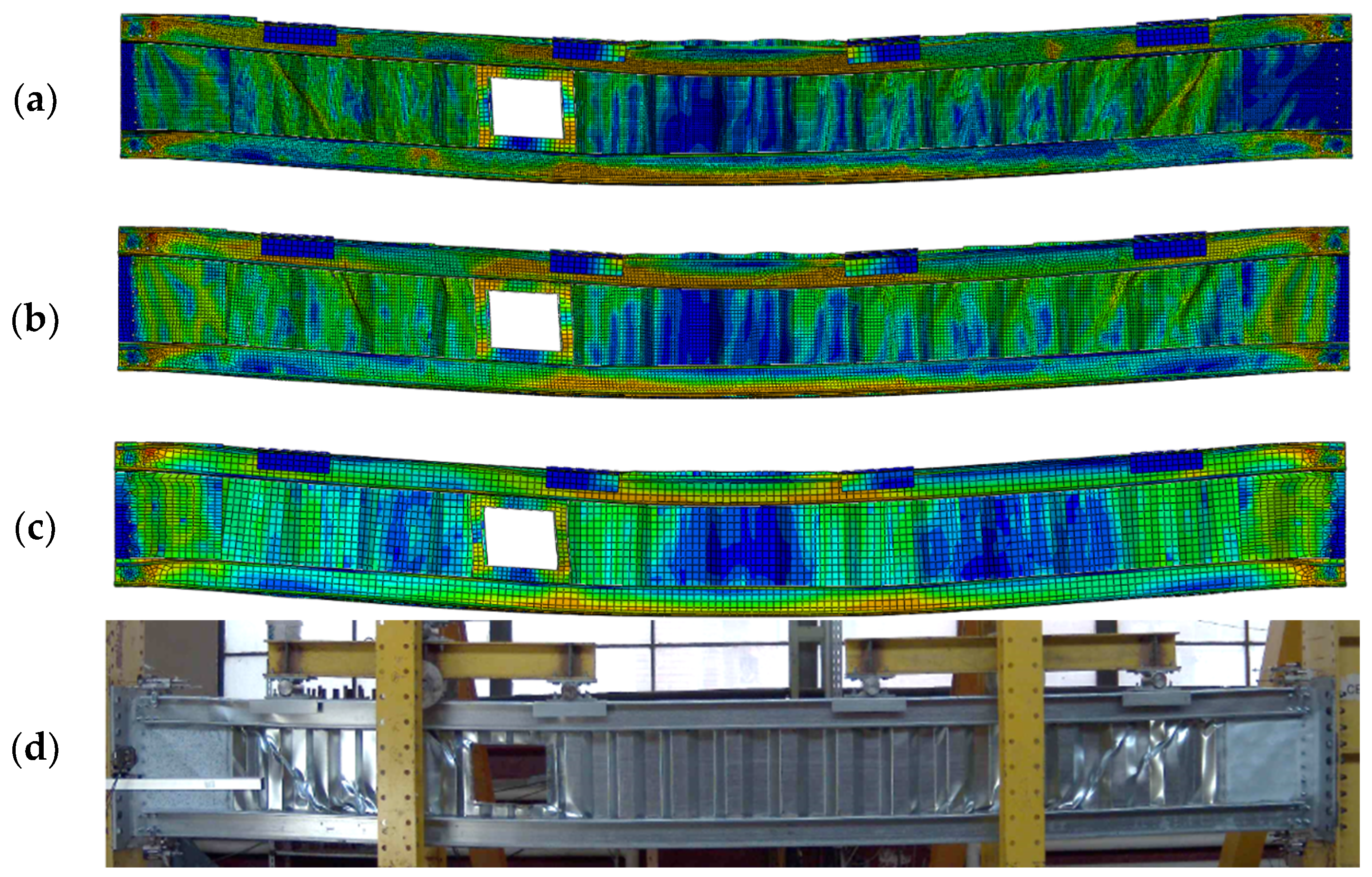
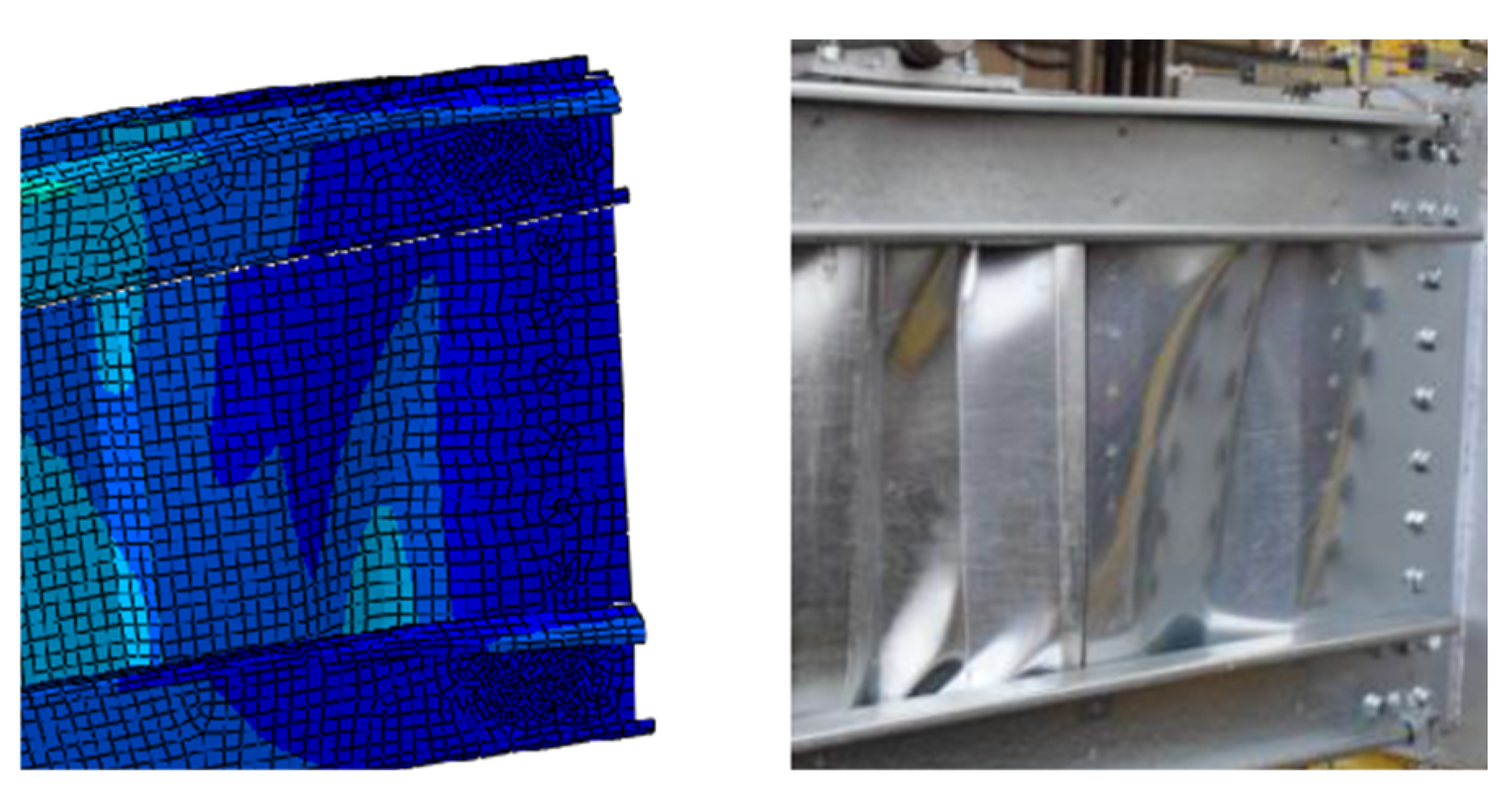
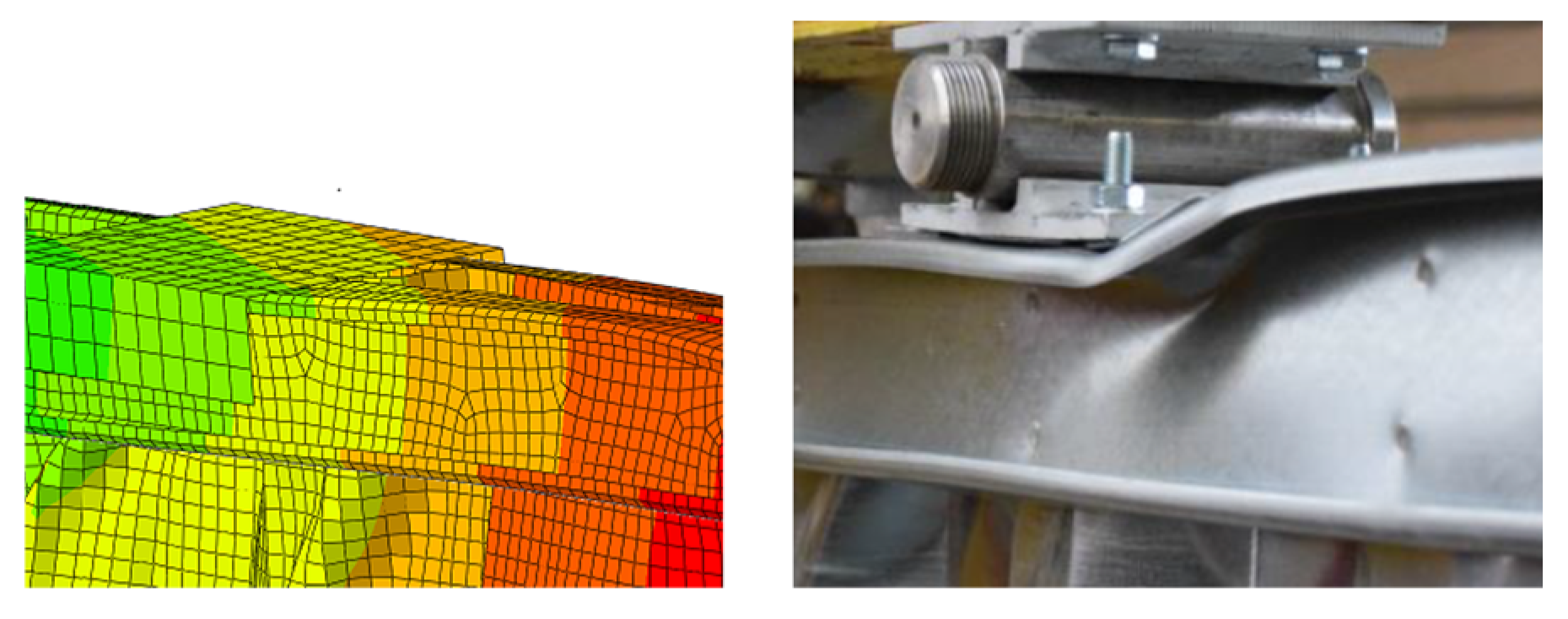
3.6. Validation of Developed FE Model

The FE model was calibrated according to the experimental results to determine the input parameters such as material properties and tensile shear tests on the lap joint welded specimens.
The calibration was influenced by the extent of initial imperfections that were introduced considering a global out-of-plane displacement of L/2500 and a vertical displacement of L/1500. The numerical simulation consisted of two steps: (1) nonlinear static analysis—used to introduce the initial imperfections and (2) nonlinear dynamic explicit analysis—used to obtain the load–displacement curve of the beam based on the deformed shape from the previous analysis.
A global mesh size of 15 mm was used for flanges, corrugated web, and shear panels considering the mesh sensitivity analysis presented before.
A general contact between all elements in the model was used with the following parameters: normal direction, hard contact, transverse direction, and a friction coefficient of μ = 0.1. Furthermore, separation was allowed after the general contact took place.
The calibrated model was validated in terms of stiffness, failure modes, and buckling modes. Similar failure and buckling modes were observed. Figure 13 shows the local buckling of the shear panels in the vicinity of the supports, Figure 14 presents the failure of a spot weld captured also in the FE analysis, and Figure 15 shows the deformations observed under the displacement application points.
Figure 16 presents the force–displacement curve obtained during the experiment that correlated well with the one from the numerical analysis. Generally, the FE model underestimates resistance. Some differences in terms of stiffness were also observed, which can be explained by the flexibility of the experimental frame that was used to load the beams.

4. Parametric Numerical Study

This parametric study was conducted to study the influence of different parameters that have a major effect on the performance of the built-up cold-formed steel beam. The influence of different components was analyzed through the parametric study considering beams with three lengths, i.e., (1) 6000 mm, (2) 7500 mm, and (3) 9000 mm, with and without web openings. The lengths of the beams considered in the parametric study were common for multi-story buildings due to their structural efficiency, chosen based on functionality criteria for the building (e.g., minimum dimensions of the parking lots).
The parameters are presented in Table 1. The thicknesses of the steel sheets and the profiles sections were chosen considering the usual sections that can be found on the market.
It is important to mention that some parameters have a negligible influence on the global behavior of the built-up cold-formed steel beam, but they can influence the local behavior.
All the parameters presented in Table 1 were studied for the built-up beam with a length of 6000 mm with web openings, thus resulting in 20 numerical simulations. After that, the parameters with a small influence on the results were neglected and only the parameters with significant influence were studied for the beams with lengths of 7500 and 9000 mm. In total, 61 simulations were found. The results are presented in Figure 17, Figure 18, Figure 19, Figure 20, Figure 21 and Figure 22.
Considering the large number of parameters identified, a Python script was developed in order to automate the pre-process phase of the parametric study. The results of the most significant parameters are presented in the following chapters. The calibrated numerical model was modified using the Python script (.py), which generates the input files for Abaqus (.inp) in this way. To ease the use of the script without involving broad programming skills, a graphical user interface (GUI) was developed in Really Simple GUI Dialog Builder (RSG).

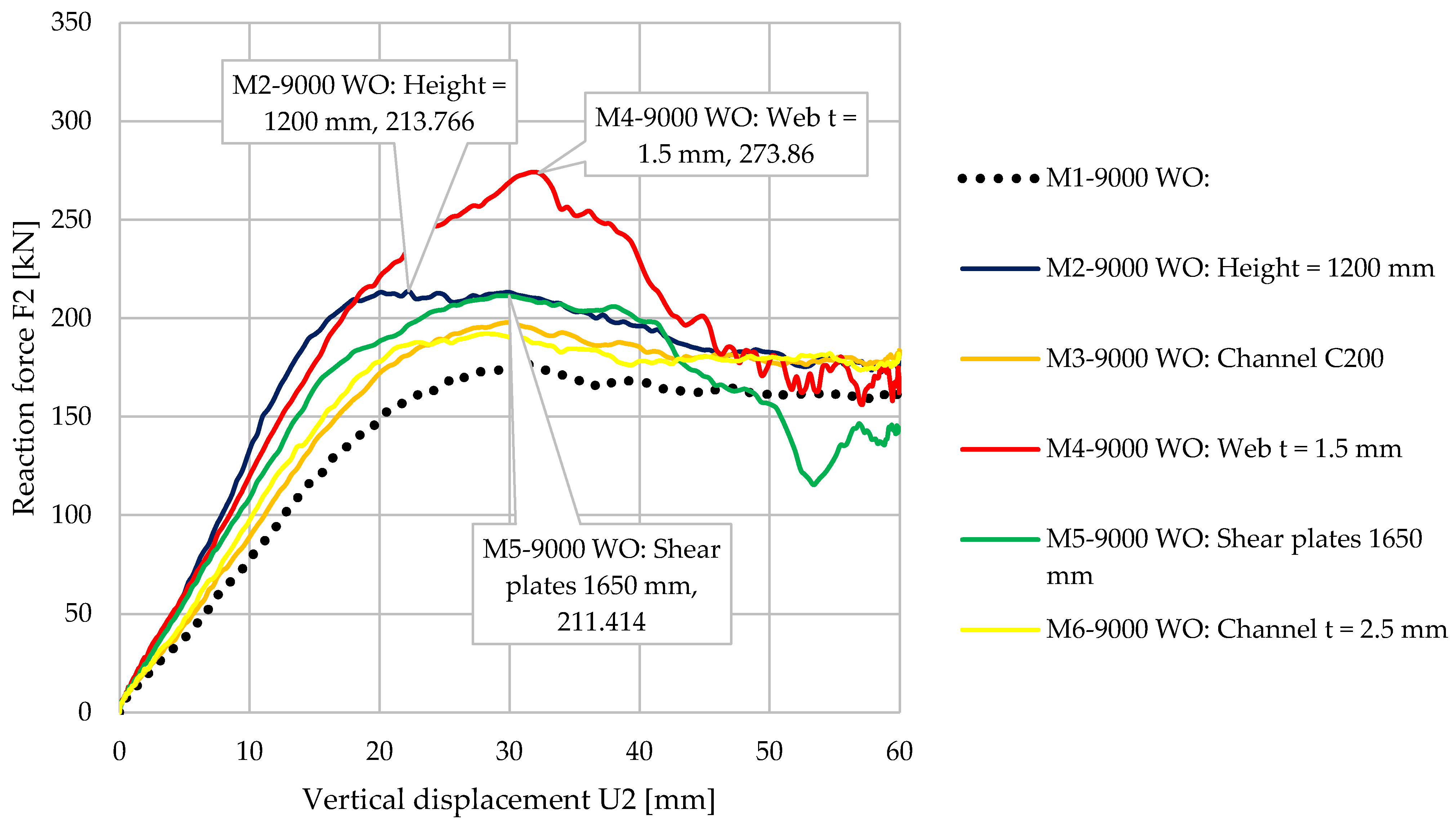
4.1. Influence of the Beam’s Height

The influence of the height of the beams was investigated by changing the height of the beams from 800 mm to 1200 mm. The ratio between the span and the height ranged between 6 and 10. The lateral displacements of the lower and upper flanges were blocked at one third (Lb = L/3) and two thirds (Lb = 2L/3) of the span. All the other parameters were kept constant.
For this analysis, models with web openings (WOs) and models without (R) were considered. The names chosen for each model indicate the lengths used for the beams (e.g., 6000—beam with a length of 6000 mm).
An increase in the bearing capacity could be observed when the height of the beam increased. The increase was approximately 6% for beams with a length of 6000 mm and reached 20–25% for beams with a length of 9000 mm. The same behavior was also observed in terms of stiffness, with a larger increase for longer beams. It can be concluded that for short beams, the shear stress was dominant; therefore, the height is an important parameter for long beams where the bending moment is dominant.
The influence of the web opening on the bearing capacity was small. However, the presence of the web opening was more important for beams with a length of 9000 mm. Table 2 summarizes the results. Figure 23 shows that by increasing the beam height from 600 mm to 1200 mm, we could obtain a significant increase in bearing capacity and stiffness for the beams with a length of 9000 mm.

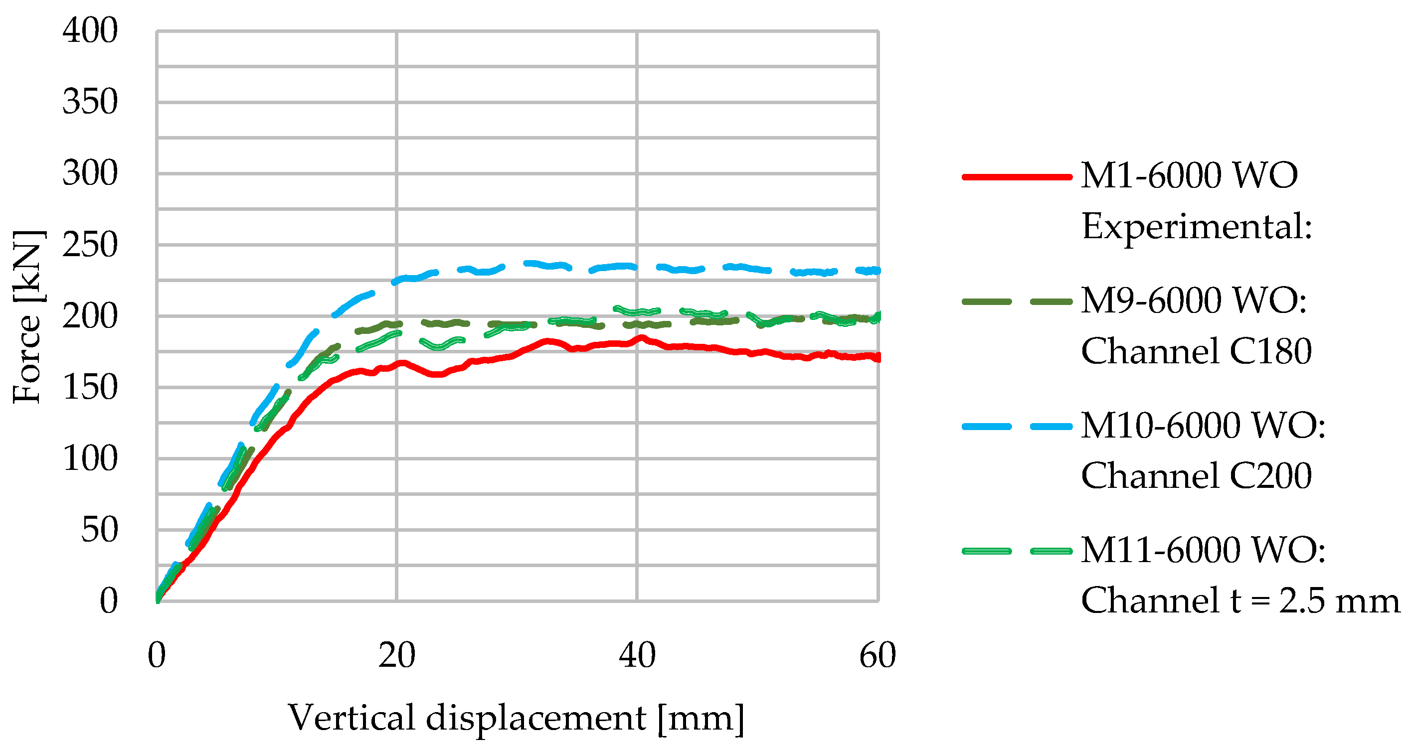
4.2. Influence of the Section and Thickness of the Flanges

Other research works on corrugated web beams showed that the flanges play a crucial role in the bearing capacity of beams in bending, while the web mainly contributes to the shear resistance [3,45]. Similar conclusions were also drawn from this study. Table 3 shows that for the beam with a length of 6000 mm, by changing the section from C150 to C200, an increase in the bearing capacity of 28% could be obtained. The increase was more significant for beams when web openings were present.
Figure 24 shows the force–displacement curves for the 6000 mm length beam with a web opening. An increase in bearing capacity and a slight increase in stiffness could be observed when the areas of the flanges increased. It is important to note that it was more efficient to increase the size of the section than to increase the thickness of the steel profile. It must be mentioned that increasing the thickness or area of the flange impacts the initial stiffness of the beam.

4.3. Influence of the Shear Panels

The length of the shear panels changed from 600 mm to 1650 mm. The parametric numerical study showed that the influence on rigidity or resistance was not significant. The impact of changing the length of the shear panels on beam performance was smaller than in the case of flanges or beam height. The results are presented in Table 4 below.

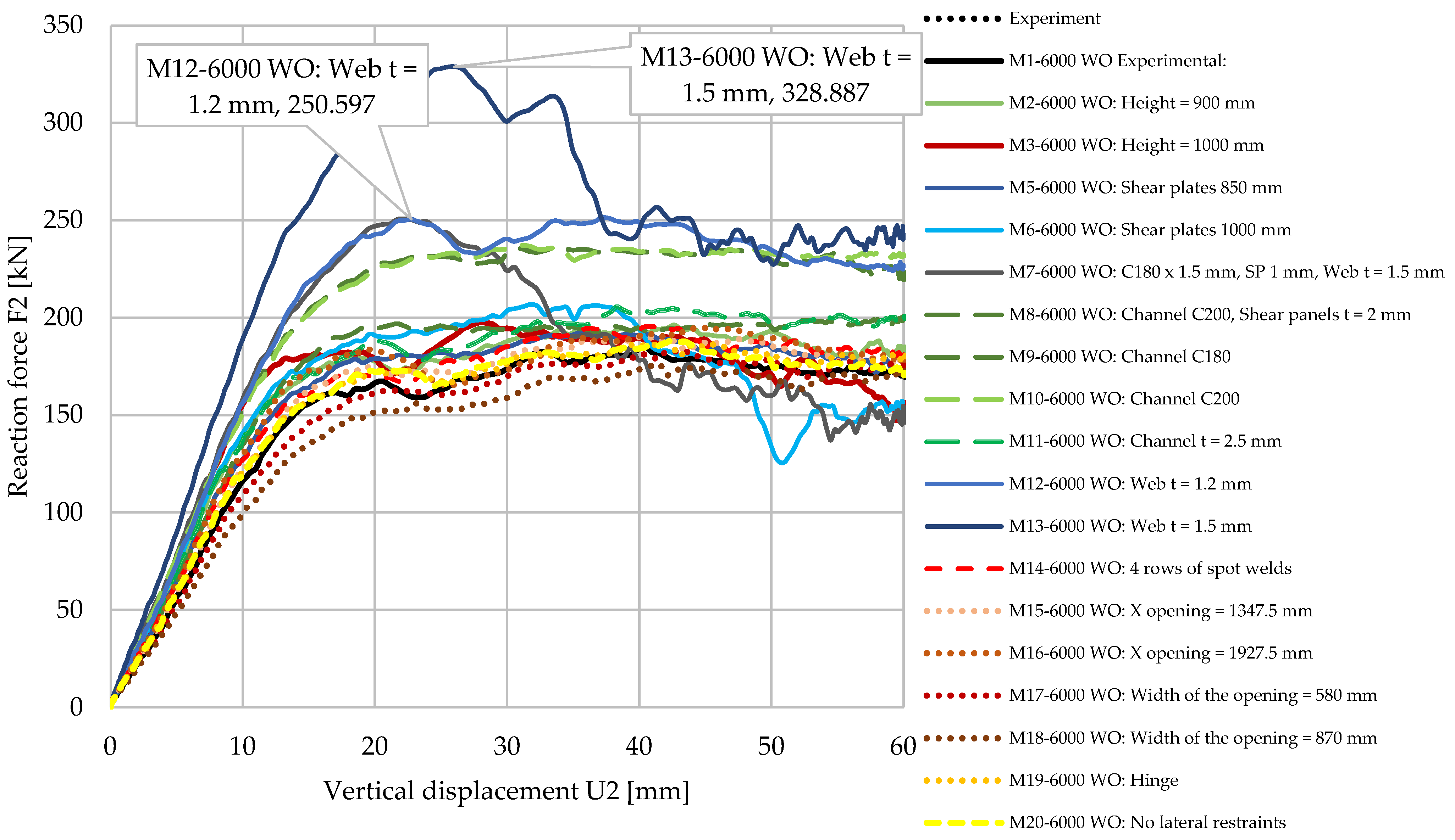
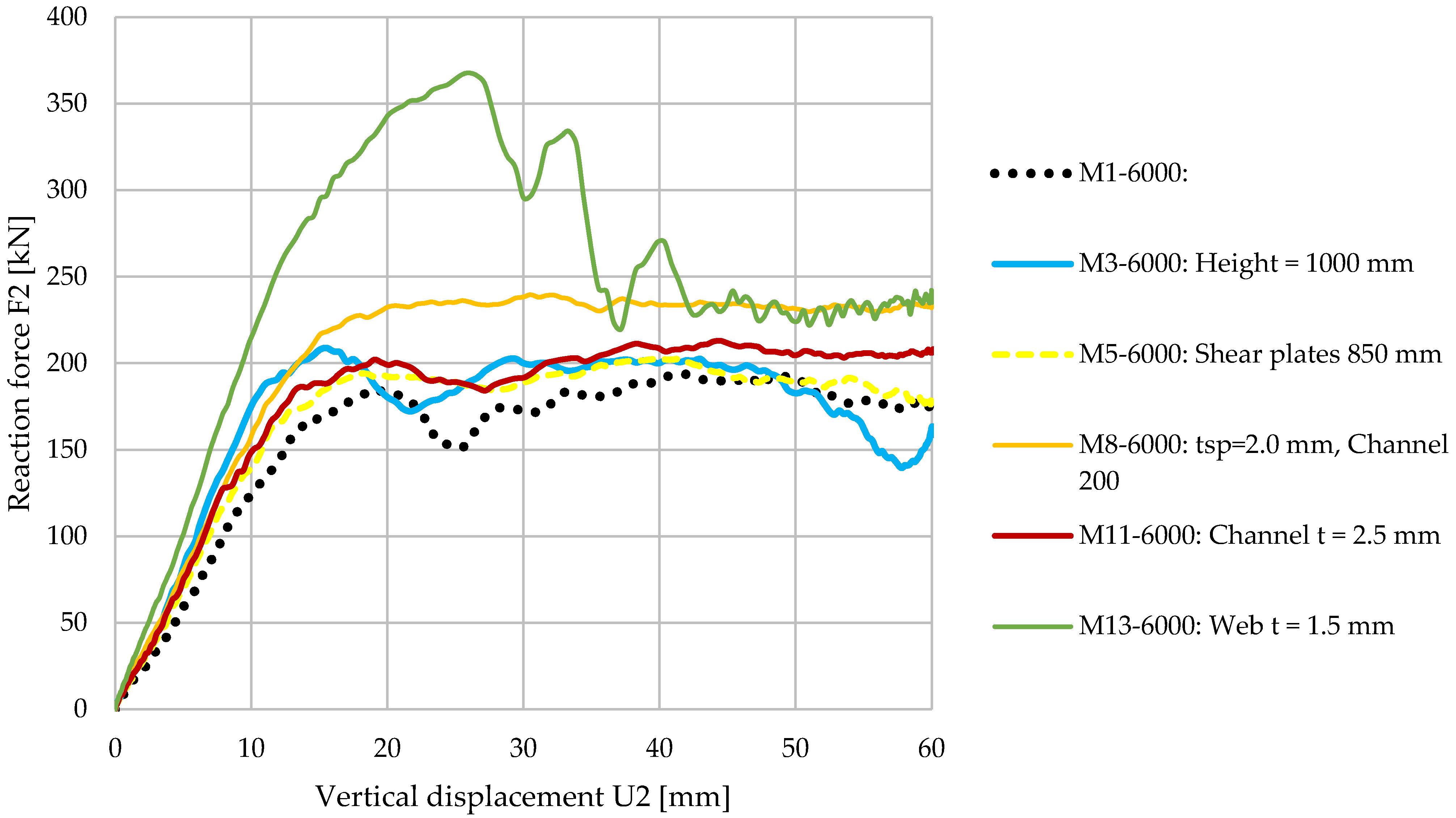
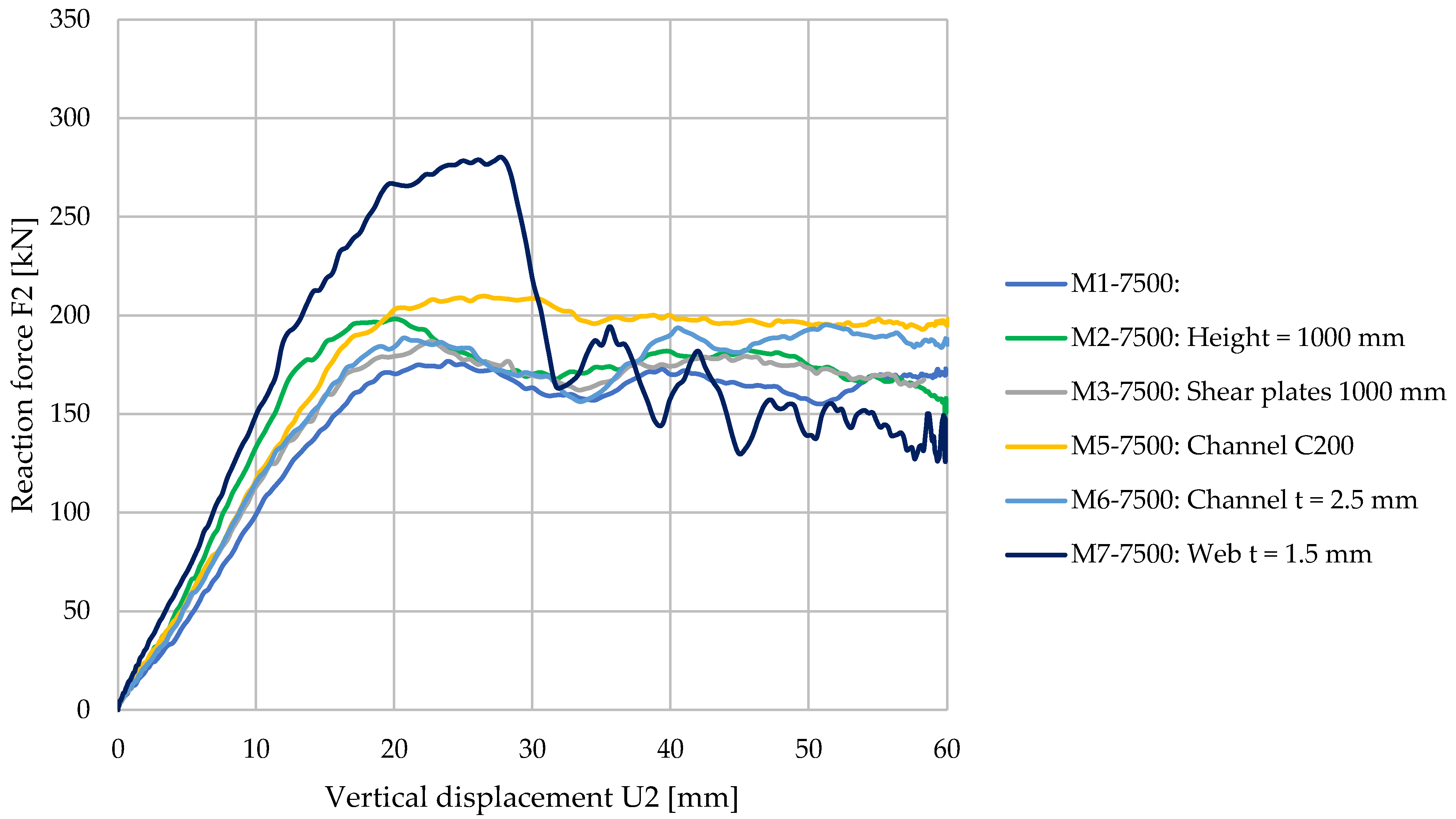
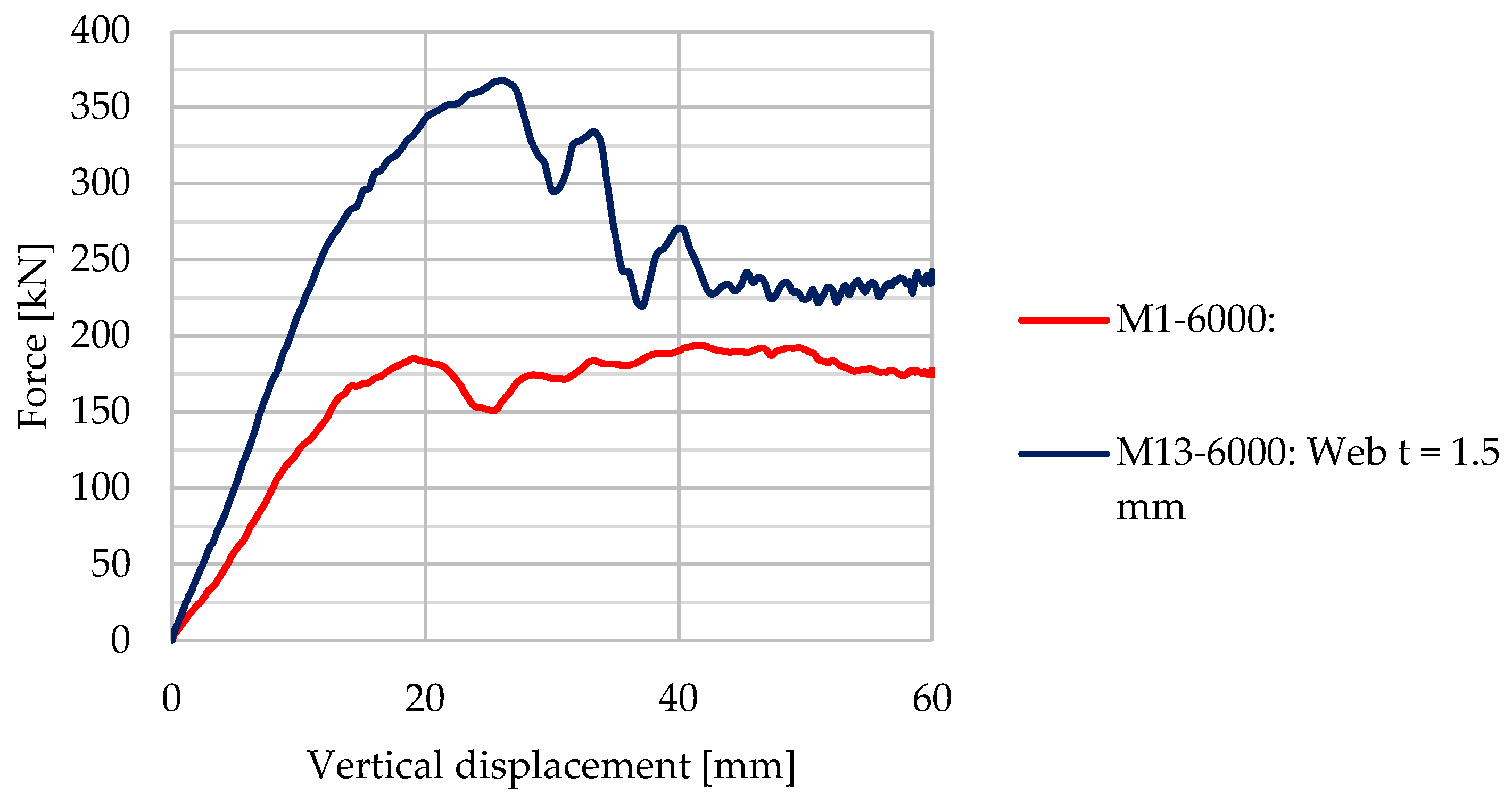
4.4. Influence of Corrugated Web Thickness

The influence of the thickness of the corrugated web was also investigated. The thickness of the web varied between 1.0 and 1.50 mm, demonstrating a constant thickness for the entire length of the beam. A strong effect was recorded in the case of web thickness. Table 5 presents the bearing capacity and the stiffness of the beams for various web thicknesses.
Changing the web thickness parameter had a greater influence on short beams (see Figure 25 and Figure 26), both in terms of bearing capacity and stiffness. After the maximum force was reached, an abrupt decrease could be observed in the force–displacement curves. This can lead to the conclusion that the behavior of the beam is dominated by the weakest component. After reaching the peak force, instability phenomena were recorded in the corrugated web, leading to a decrease in the bearing capacity.
As was shown in other research papers [3,10], the flexural capacity of the beam was highly dependent on the flanges, while transverse forces were transferred through the corrugated web. Therefore, it can be concluded that the behavior of the well-formed beam solution was dominated by the shear capacity of the corrugated web.
The recorded failure modes are presented in Figure 27. For the beam with a length of 6000 mm and WO, the local instabilities under the points of load application were found to be significant, representing the weakest component for the web thickness of 1.00 mm. For the same beam, considering a thickness of the corrugated web up to 1.50 mm, the failure modes changed and the failure occurred due to the local buckling of the shear panels in the vicinity of the supports and the distortion of corrugations connected to the lower flange.

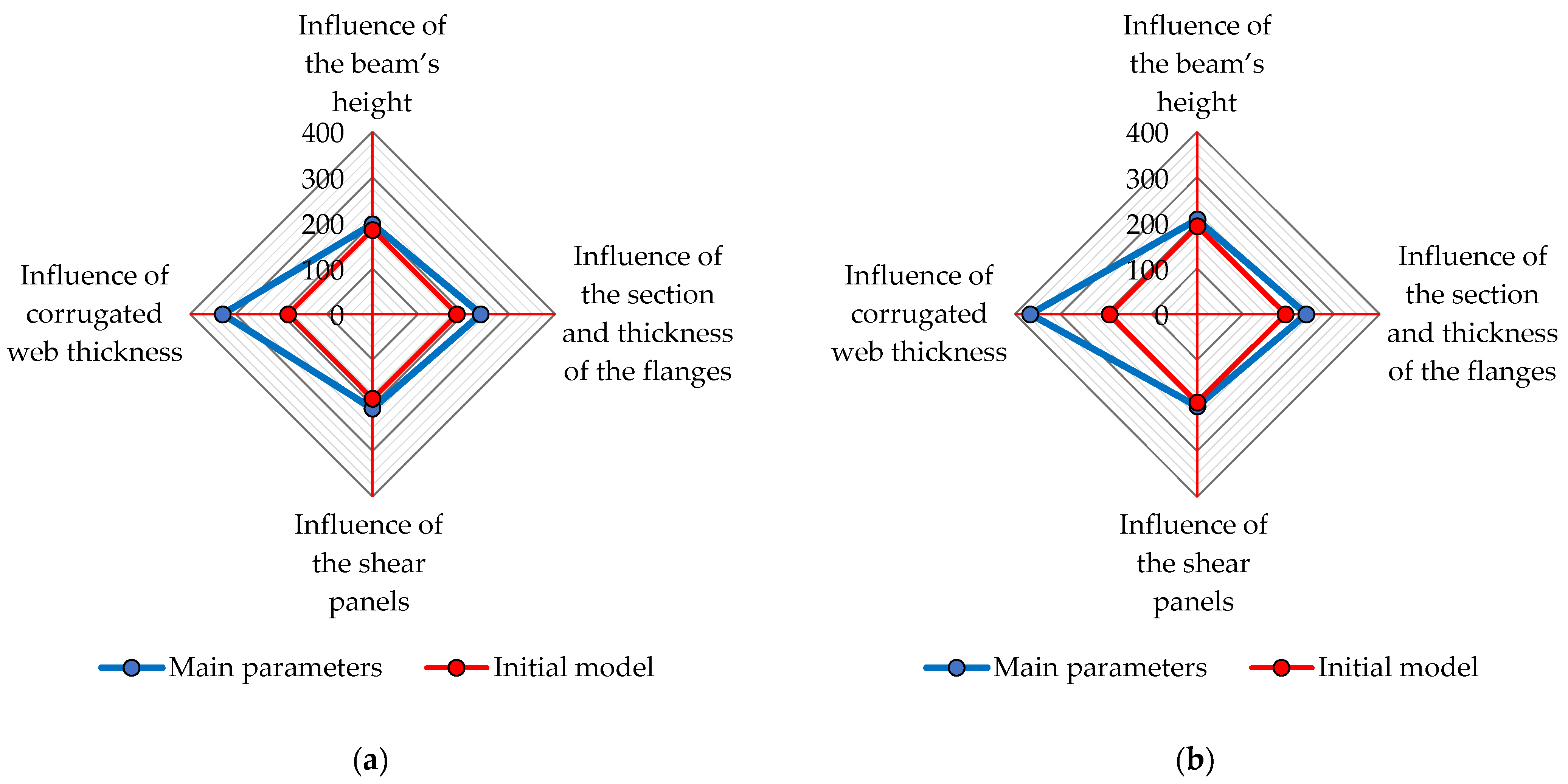
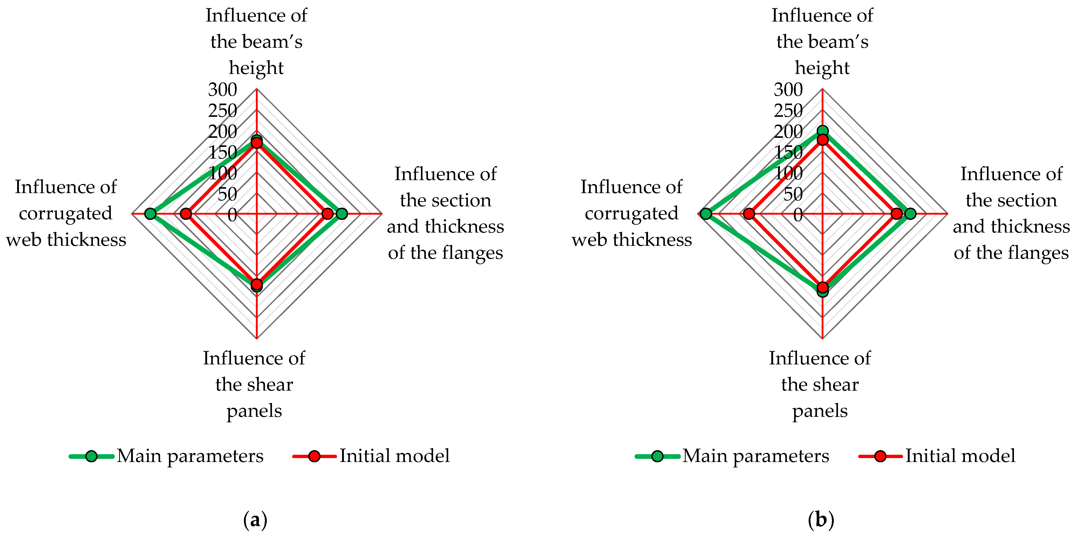
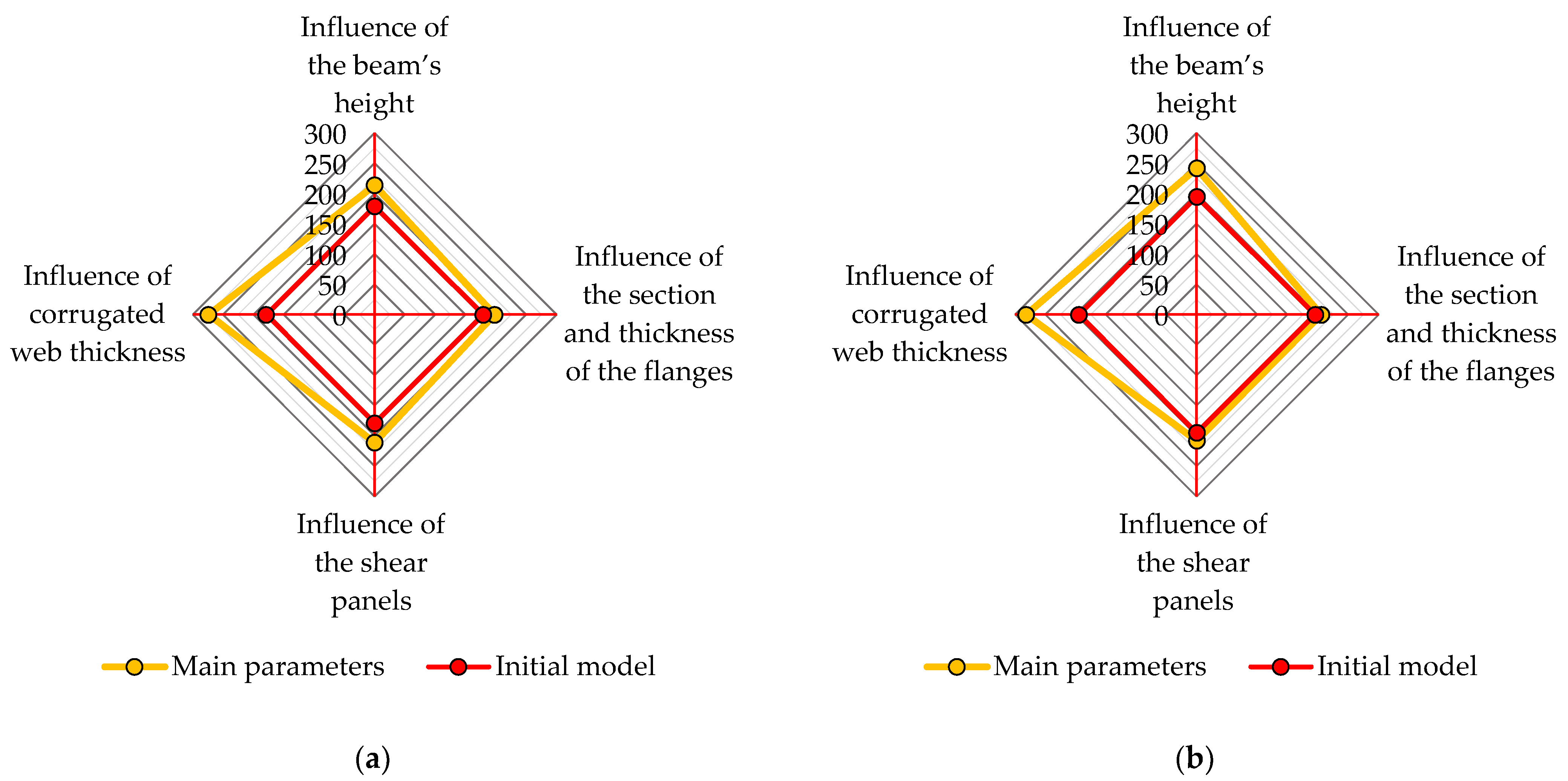
4.5. Summary of the Main Parameters

The main parameters which influence the behavior of the built-up cold-formed steel beam were found to be the height of the beam, the section and thickness of the flanges, the thickness and length of the shear panels, and the thickness of the corrugated web. The main parameters are presented in terms of maximum force in Figure 28, Figure 29 and Figure 30 for each beam.

5. Conclusions and Future Research

Corrugated web beams with web openings are very efficient solutions when used as secondary beams in floor systems because of the reduced weight of the solution. Spot welding significantly increases work productivity and enables automated fabrication to develop the mass production of these types of beams. Another major advantage is the high protection against corrosion because all components are galvanized.
The paper investigates these types of beams using numerical analysis. An FE model was built, calibrated, and validated using the experimental campaign conducted within the well-formed research project. The FE model includes all the essential physical features from the tested specimens and predicted the failure modes, bearing capacity, and stiffness recorded in the experiments.
Beams with three lengths, namely the usual spans for secondary beams, were studied, i.e., (1) 6000 mm, (2) 7500 mm, and (3) 9000 mm, with and without web openings.
To better characterize the solution, a parametric study was conducted to identify the key parameters. The influence of different components (parameters) was analyzed in this study. Finally, the main parameters (in order of importance) that influence the behavior of the built-up cold-formed steel beam are: (1) the thickness of the corrugated steel sheet used for the web; (2) the section and thickness of the flanges; (3) the height of the beam; and (4) the thickness and length of the shear panels.
Due to the large number of parameters which could influence the performance of the proposed structural solution, an algorithm was developed in Python to automate the pre-processing phase. The algorithm was integrated in a GUI in Abaqus software and was used to create a large number of models. A total number of 61 simulations were considered for the parametric study. However, only the parameters that contribute significantly to the beam performance are presented in detail in this paper.
The main conclusions referring to the parametric study are as follows:
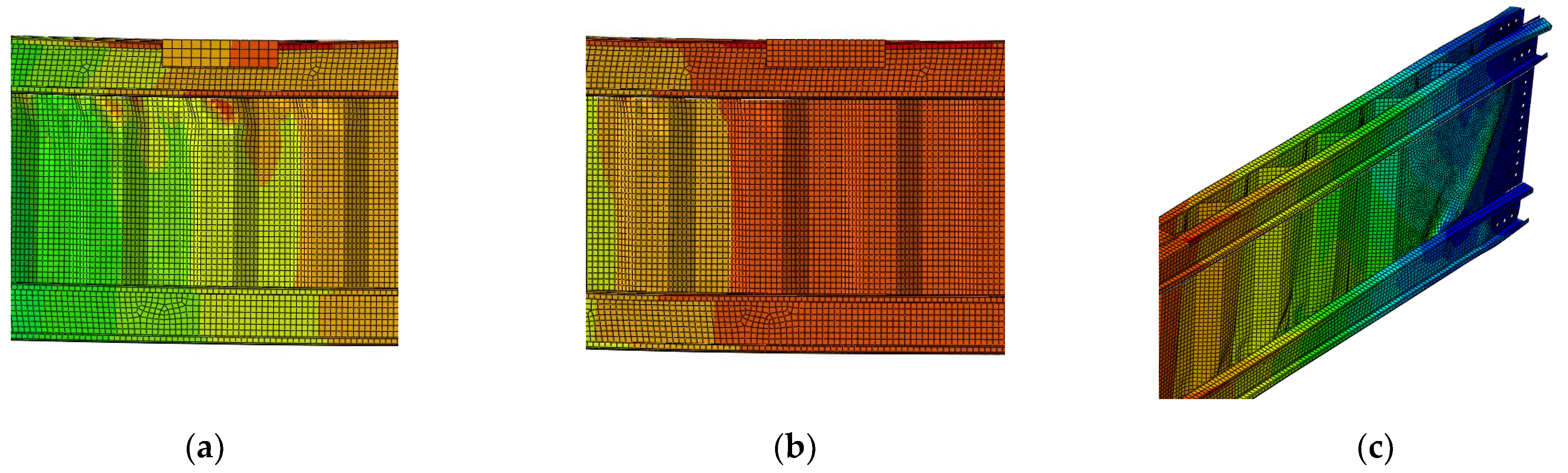
  • The flanges that carry the bending moments and the webs, due to their corrugations, are not able to carry any normal stresses, only shear stresses. Beams with corrugated webs behave similarly to lattice girders.
  • By changing the area of the flange, an increase in the bearing capacity is obtained, especially increasing the height of the flange cross-section. The increase is more significant for beams where there are web openings.
  • The corrugated web appears to be the weakest component of the structural system. Increased web thickness can lead to major improvements in both the strength and stiffness of the beam. The behavior of such a beam is dominated by the shear capacity of the corrugated web. An improvement in the fabrication process, by fabricating thicker webs, leads to significant improvements in the capacity and stiffness of CWB beams.
  • An increase in bearing capacity can be observed when the height of the beam increases.
  • The impact of changing the length of the shear panels on beam performance is much smaller than the contribution of the flanges or beam height.
  • The presence of a stiffened web opening reduces the bearing capacity of the beam. However, the proposed reinforced solution significantly decreases the impact of the web opening, which led to a decrease of up to 50% in the strength in other studies.
It is important to note that the beam was loaded only in two points, while in the experiments it was loaded in four points. This changes the load from a uniformly distributed load to a static scheme with two concentrated forces. Hence, the instability phenomena under the load application points are significant. This can also explain the high influence of the web thickness that is affected by local buckling under these points.
Further studies will be conducted within a new research project under development, i.e., well-formed frames. It is known in the literature that cold-formed steel connections have a semi-rigid behavior. In the parametric study presented above, both hinged and fixed configurations of the beams were studied. The local behavior of the end connections will be studied in the future to find the main factors that affect the stiffness and bearing capacity of it. Standardized connection joints will be proposed. Furthermore, real-scale tests will be performed on well-formed frames considering the proposed connection joints and the results from this parametric study.

Author Contributions

Conceptualization, V.U. and A.A.C.; methodology, V.U. and A.A.C.; software V.U. and A.A.C.; validation A.A.C., formal analysis, V.U.; investigation, V.U.; resources, V.U.; data curation, V.U.; writing—original draft preparation, A.A.C.; writing—review and editing, V.U.; visualization, A.A.C.; supervision, V.U.; project administration, V.U.; funding acquisition, V.U. and A.A.C. All authors have read and agreed to the published version of the manuscript.

Funding

This work was supported by a grant of the Romanian Ministry of Research and Innovation, CCCDI—UEFISCDI, project number PN-III-P2-2.1-PTE-2021-0237-Wellformed-Frames.

Data Availability Statement

The data presented in this study are available on request from the corresponding author.

Conflicts of Interest

The authors declare no conflict of interest.

References

  1. Elgaaly, M.; Dagher, H. Beams and Girders with Corrugated Webs. In Proceedings of the Structural Stability Research Council, Annual Technical Session, Stability of Bridges, St. Louis, MO, USA, 10–11 April 1990. [Google Scholar]
  2. Luo, R.; Edlund, B. Numerical Simulation of Shear Tests on Plate Girders with Trapezoidally Corrugated Webs; Division of Steel and Timber Structures; Chalmers University of Technology: Gothenburg, Sweden, 1995. [Google Scholar]
  3. Elgaaly, M.; Seshadri, A.; Rodriquez, R.; Ibrahim, S. Bridge Girders with Corrugated Webs. Transp. Res. Rec. J. Transp. Res. Board 2000, 5, 162–170. [Google Scholar] [CrossRef]
  4. Johnson, R.P.; Cafolla, J. Local Flange Buckling in Plate Girders with Corrugated Webs. Proc. Inst. Civ. Eng Struct. Build. 1997, 122, 148–156. [Google Scholar] [CrossRef]
  5. Chan, C.L.; Khalid, Y.A.; Sahari, B.B.; Hamouda, A.M.S. Finite Element Analysis of Corrugated Web Beams under Bending. J. Constr. Steel Res. 2002, 58, 1391–1406. [Google Scholar] [CrossRef]
  6. Lindner, J. Lateral-Torsional Buckling of Beams with Trapezoidally Corrugated Webs. In Proceedings of the 4th International Colloquium Stab. Steel Structures, Budapest, Hungary, 5–7 June 1990. [Google Scholar]
  7. Pasternak, H.; Robra, J.; Kubieniec, G. New Proposals for EN 1993-1-5, Annex D: Plate Girders with Corrugated Webs. In Proceedings of the Codes in Structural Engineering Joint IABSE-fib Conference, Dubrovnik, Croatia, 3–5 May 2010; pp. 1365–1372. [Google Scholar]
  8. EN 1993-1-5; Eurocode 3: Design of Steel Structures—Part 1–5: Plated Structural Elements. CEN: Brussels, Belgium, 2006.
  9. Luo, R.; Edlund, B. Ultimate Strength of Girders with Trapezoidally Corrugated Webs under Patch Loading. Thin Walled Struct. 1996, 24, 135–156. [Google Scholar] [CrossRef]
  10. Kövesdi, B.; Jáger, B.; Dunai, L. Stress Distribution in the Flanges of Girders with Corrugated Webs. J. Constr. Steel Res. 2012, 79, 204–215. [Google Scholar] [CrossRef]
  11. Zhao, W. Behaviour and Design of Cold-Formed Steel Sections with Hollow Flanges. Ph.D. Thesis, Queensland University of Technology, Brisbane, Australia, 2005. [Google Scholar]
  12. Wanniarachchi, S. Flexural Behaviour and Design of Cold-Formed Steel Beams with Rectangular Hollow Flanges. Ph.D. Thesis, Queensland University of Technology, Brisbane, Australia, 2005. [Google Scholar]
  13. Smith, D.A. Behavior of Corrugated Plates Subjected to Shear. Master’s Thesis, Civil Engineering, University of Maine, Orono, ME, USA, 1992. [Google Scholar]
  14. Landolfo, R.; Mammana, O.; Portioli, F.; Di Lorenzo, G.; Guerrieri, M.R. Thin-Walled Structures Laser Welded Built-up Cold-Formed Steel Beams. Exp. Investig. 2008, 46, 781–791. [Google Scholar] [CrossRef]
  15. Di, G.; Landolfo, L.R. Study of Innovative Built-Up Cold-Formed Beams Study of Innovative Built-Up Cold-Formed Beams. In Proceedings of the International Specialty Conference on Cold-Formed Steel Structures, Orlando, FL, USA, 26–27 October 2002. [Google Scholar]
  16. Kanthasamy, E.; Hussain, J.; Thirunavukkarasu, K.; Poologanathan, K.; Roy, K.; Beulah Gnana Ananthi, G.; Suntharalingam, T. Flexural Behaviour of Built-Up Beams Made of Optimised Sections. Buildings 2022, 12, 1868. [Google Scholar] [CrossRef]
  17. Dubina, D.; Ungureanu, V.; Gîlia, L. Cold-Formed Steel Beams with Corrugated Web and Discrete Web-to-Flange Fasteners. Steel Constr. 2013, 6, 74–81. [Google Scholar] [CrossRef]
  18. Dubina, D.; Ungureanu, V.; Gîlia, L. Experimental Investigations of Cold-Formed Steel Beams of Corrugated Web and Built-up Section for Flanges. Thin Walled Struct. 2015, 90, 159–170. [Google Scholar] [CrossRef]
  19. Ungureanu, V.; Both, I.; Burca, M.; Radu, B.; Neagu, C.; Dubina, D. Experimental and numerical investigations on built-up cold-formed steel beams using resistance spot welding. Thin Walled Struct. 2021, 161, 107456. [Google Scholar] [CrossRef]
  20. Romeijn, A.; Sarkhosh, R.; de Hoop, H. Basic Parametric Study on Corrugated Web Girders with Cut Outs. J. Constr. Steel Res. 2009, 65, 395–407. [Google Scholar] [CrossRef]
  21. Al-Dafafea, T.; Durif, S.; Bouchaïr, A.; Fournely, E. Experimental Study of Beams with Stiffened Large Web Openings. J. Constr. Steel Res. 2019, 154, 149–160. [Google Scholar] [CrossRef]
  22. Russell, M.J.; Lim, J.B.P.; Roy, K.; Clifton, G.C.; Ingham, J.M. Welded steel beam with novel cross-section and web openings subject to concentrated flange loading. Structures 2020, 24, 580–599. [Google Scholar] [CrossRef]
  23. Feng, R.; Zhan, H.; Meng, S.; Zhu, J. Experiments on H-shaped high-strength steel beams with perforated web. Eng. Struct. 2018, 177, 374–394. [Google Scholar] [CrossRef]
  24. Feng, R.; Liu, J.; Chen, Z.; Roy, K.; Chen, B.; Lim, J.B.P. Numerical investigation and design rules for flexural capacities of H-section high-strength steel beams with and without web openings. Eng. Struct. 2020, 225, 111278. [Google Scholar] [CrossRef]
  25. Meng, B.; Hao, J.; Zhong, W.; Tan, Z.; Duan, S. Improving collapse-resistance performance of steel frame with openings in beam web. Structures 2020, 27, 2156–2169. [Google Scholar] [CrossRef]
  26. Seo, J.K.; Mahendran, M. Plastic Bending Behaviour and Section Moment Capacities of Mono-Symmetric LiteSteel Beams with Web Openings. Thin Walled Struct. 2011, 49, 513–522. [Google Scholar] [CrossRef] [Green Version]
  27. Mahendran, M.; Keerthan, P. Experimental Studies of the Shear Behavior and Strength of LiteSteel Beams with Stiffened Web Openings. Eng. Struct. 2013, 49, 840–854. [Google Scholar] [CrossRef] [Green Version]
  28. Acharya, S.R.; Sivakumaran, K.S.; Young, B. Reinforcement Schemes for Cold-Formed Steel Joists with a Large Web Opening in Shear Zone—An Experimental Investigation. Thin Walled Struct. 2013, 72, 28–36. [Google Scholar] [CrossRef]
  29. Wang, L.; Young, B. Design of cold-formed steel built-up sections with web perforations subjected to bending. Thin Walled Struct. 2017, 120, 458–469. [Google Scholar] [CrossRef]
  30. Yu, N.; Kim, B.; Yuan, W.; Li, L.; Yu, F. An analytical solution of distortional buckling resistance of cold-formed steel channel-section beams with web openings. Thin Walled Struct. 2019, 135, 446–452. [Google Scholar] [CrossRef]
  31. Lawson, R.M.; Basta, A. Deflection of C section beams with circular web openings. Thin Walled Struct. 2019, 134, 277–290. [Google Scholar] [CrossRef]
  32. Osgouei, A.J.; Hosseinzadeh, Y.; Ahmadi, H. Local buckling analysis of cold-formed steel webs with stiffened rectangular openings. J. Constr. Steel Res. 2020, 167, 105824. [Google Scholar] [CrossRef]
  33. Uzzaman, A.; Lim, J.B.P.; Nash, D.; Rhodes, J.; Young, B. Cold-Formed Steel Sections with Web Openings Subjected to Web Crippling under Two-Flange Loading Conditions—Part I: Tests and Finite Element Analysis. Thin Walled Struct. 2012, 56, 38–48. [Google Scholar] [CrossRef] [Green Version]
  34. Uzzaman, A.; Lim, J.B.P.; Nash, D.; Rhodes, J.; Young, B. Cold-Formed Steel Sections with Web Openings Subjected to Web Crippling under Two-Flange Loading Conditions—Part II: Parametric Study and Proposed Design Equations. Thin Walled Struct. 2012, 56, 79–87. [Google Scholar] [CrossRef] [Green Version]
  35. Uzzaman, A.; Lim, J.B.P.; Nash, D.; Roy, K. Web crippling behaviour of cold-formed steel channel sections with edge-stiffened and unstiffened circular holes under interior-two-flange loading condition. Thin Walled Struct. 2020, 157, 106813. [Google Scholar] [CrossRef]
  36. Pham, S.H.; Pham, C.H.; Hancock, G.J. Direct Strength Method of Design for Channel Sections in Shear with Square and Circular Web Holes. J. Struct. Eng. 2017, 143, 04017017. [Google Scholar] [CrossRef]
  37. Pham, S.H.; Pham, C.H.; Rogers, C.A.; Hancock, G.J. Shear Strength Experiments and Design of Cold-Formed Steel Channels with Web Holes. J. Struct. Eng. 2020, 146, 04019173. [Google Scholar] [CrossRef]
  38. Pham, D.K.; Pham, C.H.; Pham, S.H.; Hancock, G.J. Experimental investigation of high strength cold-formed channel sections in shear with rectangular and slotted web openings. J. Constr. Steel Res. 2020, 165, 105889. [Google Scholar] [CrossRef]
  39. Kiymaz, G.; Coskun, E.; Cosgun, C.; Seckin, E. Transverse Load Carrying Capacity of Sinusoidally Corrugated Steel Web Beams with Web Openings. Steel Compos. Struct. 2010, 10, 69–85. [Google Scholar] [CrossRef]
  40. Ungureanu, V.; Both, I.; Neagu, C.; Burca, M.; Dubina, D.; Cristian, A.A. Built-Up Cold-Formed Steel Beams with Web Openings. In Proceedings of the International Colloquia on Stability and Ductility of Steel Structures (SDSS 2019), Prague, Czech Republic, 11–13 September 2019; pp. 1185–1192. [Google Scholar]
  41. Cristian, A.A.; Ungureanu, V. Numerical Investigation of Built-up Cold-Formed Steel Beams with Web Opening 2020. In Proceedings of the 19th National Technical-Scientific Conference “Modern Technologies for the 3rd Millennium”, Oradea, Romania, 23 October 2020; pp. 177–184. [Google Scholar]
  42. EN 1993-1-3; Eurocode 3: Design of steel Structures. Part 1–3: General Rules. Supplementary Rules for Cold-Formed Thin Gauge Members and Sheeting. CEN: Brussels, Belgium, 2006.
  43. ISO 6892-1:2019; Metallic Materials—Tensile Testing—Part 1: Method of Test at Room Temperature. ISO: Geneva, Switzerland, 2019.
  44. Dassault Systems. ABAQUS/CAE User’s Manual 6.14; Dassault Systems: Paris, France, 2014. [Google Scholar]
  45. Pasternak, H.; Kubieniec, G. Present State of Art of Plate Girders with Sinusoidally Corrugated Web. In Proceedings of the 10th International Conference on Steel, Space and Composite Structures, North Cyprus, Turkey, 16–18 May 2011; pp. 243–257. [Google Scholar]
Figure 1. Configuration of the tested built-up beams assembled by spot welding.
Buildings 13 00237 g001
Figure 2. Configuration of the tested built-up beam with web openings (aspect ratio hwo/bwo = 0.8) assembled by spot welding.
Buildings 13 00237 g002
Figure 3. Reinforcing the opening of the web.
Buildings 13 00237 g003
Figure 4. Reinforcing the web opening for the CWB-SW-WQ specimen assembled by spot welding.
Buildings 13 00237 g004
Figure 5. Reinforcement the web opening for the CWB-CMT-WO specimen assembled by MIG brazing.
Buildings 13 00237 g005
Figure 6. Deformed shape of the CWB-SW-WO assembled by spot welding.
Buildings 13 00237 g006
Figure 7. Deformed shape of the CWB-CMT-WO assembled by MIG brazing.
Buildings 13 00237 g007
Figure 8. Comparison of CWBs with web openings.
Buildings 13 00237 g008
Figure 9. The FE model.
Buildings 13 00237 g009
Figure 10. Geometrical imperfections observed in the experiment vs. FEM.
Buildings 13 00237 g010
Figure 11. Comparison of force–displacement curves for different mesh sizes.
Buildings 13 00237 g011
Figure 12. Comparison of Von Misses stresses for (a) a mesh size of 10 mm, (b) a mesh size of 15 mm, (c) a mesh size of 30 mm, and (d) the experiment [40].
Buildings 13 00237 g012
Figure 13. Local buckling of the shear panels in the vicinity of the supports.
Buildings 13 00237 g013
Figure 14. Failure of a spot weld connecting the corrugated web and the flanges.
Buildings 13 00237 g014
Figure 15. Deformations at the displacement application points.
Buildings 13 00237 g015
Figure 16. Force–displacement curves for the calibrated FE model and the experiment.
Buildings 13 00237 g016
Figure 17. Parametric study for the beam with a web opening and a length of 6000 mm.
Buildings 13 00237 g017
Figure 18. Parametric study for the beam with a web opening and a length of 7500 mm.
Buildings 13 00237 g018
Figure 19. Parametric study for the beam with a web opening and a length of 9000 mm.
Buildings 13 00237 g019
Figure 20. Parametric study for the beam without a web opening and a length of 6000 mm.
Buildings 13 00237 g020
Figure 21. Parametric study for the beam without a web opening and a length of 7500 mm.
Buildings 13 00237 g021
Figure 22. Parametric study for the beam without a web opening and a length of 9000 mm.
Buildings 13 00237 g022
Figure 23. Force–displacement curves for the beam with a web opening, a length of 9000 mm, and different heights.
Buildings 13 00237 g023
Figure 24. Force–displacement curves for the beam with a web opening, a length of 6000 mm, and different flange configurations.
Buildings 13 00237 g024
Figure 25. Force–displacement curves for the beam with a web opening, a length of 6000 mm, and corrugated webs with different thickness.
Buildings 13 00237 g025
Figure 26. Force–displacement curves for the beam without a web opening, a length of 6000 mm, and corrugated webs with different thickness.
Buildings 13 00237 g026
Figure 27. Comparison of failure modes in the final stage of loading for the beam with a web opening and a length of 6000 mm: (a) instability phenomena under the load application points for M1-6000 WO, i.e., the beam with the corrugated web thickness of 1.00 mm; (b) no instabilities were recorded under the load application points for M13-6000 WO, i.e., the beam with the corrugated web thickness of 1.50 mm; (c) failure of the M13-6000 WO beam was due to local buckling of the shear panels coupled with the distortion of the corrugations connected to the lower flange.
Buildings 13 00237 g027
Figure 28. (a) Main parameters for the beam with a length of 6000 mm and a web opening; (b) main parameters for the beam with a length of 6000 mm without a web opening.
Buildings 13 00237 g028
Figure 29. (a) Main parameters for the beam with a length of 7500 mm and a web opening; (b) main parameters for the beam with a length of 7500 mm without a web opening.
Buildings 13 00237 g029
Figure 30. (a) Main parameters for the beam with a length of 9000 mm and a web opening; (b) main parameters for the beam with a length of 9000 mm without a web opening.
Buildings 13 00237 g030
Table 1. Overview of the parameters.
CategoryDescription
Geometrical parameters of the beamLength of the beam
Height of the beam
ConnectionsDiameter of the holes
Edge distance
Number of holes and distance between them
Spot-welding parametersNumber of vertical spot-welding rows on the web
Number of corrugations overlapped with the shear panels
Number of spot welds between flanges and web
Shear panelsLength of the shear panels
Thickness of the shear panels (from 0.80 mm to 2.00 mm)
FlangesSection of the flanges (C120, C150, C180, C200, C250, C300)
Thickness of the flange’s profiles (from 0.80 mm to 2.50 mm)
Corrugated websThickness of the corrugated web (from 0.80 mm to 1.50 mm)
Length of the corrugated web and overlapping length with the shear panels
Web openingsPresence of a web opening
Width of the web opening—with a width multiple of the corrugation width
Height of the web opening—limited to the distance between flanges
Position along the length of the beam
Boundary conditionsSuppressed degrees of freedom around the holes
Block lateral displacements of the lower flange considering the presence of fly braces
Table 2. Bearing capacity of the CWB beams for different heights.
ModelHeight Maximum Force
M1-6000 WO800 mm185.14 kN
M2-6000 WO900 mm196.36 kN
M3-6000 WO1000 mm197.50 kN
M1-7500 WO850 mm169.65 kN
M2-7500 WO1000 mm175.66 kN
M1-9000 WO900 mm179.11 kN
M2-9000 WO1200 mm213.77 kN
M1-6000800 mm193.99 kN
M3-60001000 mm208.91 kN
M1-7500850 mm176.84 kN
M2-75001000 mm198.34 kN
M1-9000900 mm195.08 kN
M2-90001200 mm241.93 kN
Table 3. Bearing capacity of beams considering different configurations of flanges.
ModelSection and ThicknessMaximum Force
M1-6000 WOC1502.00 mm185.14 kN
M9-6000 WOC1802.00 mm200.73 kN
M10-6000 WOC2002.00 mm237.14 kN
M11-6000 WOC1502.50 mm205.63 kN
M1-7500 WOC1502.00 mm169.65 kN
M5-7500 WOC2002.00 mm203.80 kN
M6-7500 WOC1502.50 mm184.17 kN
M1-9000 WOC1802.00 mm179.11 kN
M3-9000 WOC2002.00 mm197.82 kN
M1-6000C1502.00 mm193.99 kN
M8-6000C2002.00 mm239.67 kN
M1-7500C1502.00 mm176.84 kN
M5-7500C2002.00 mm209.84 kN
M6-7500C1502.50 mm195.21 kN
M1-9000C1802.00 mm195.08 kN
M3-9000C2002.00 mm202.65 kN
M6-9000C1802.50 mm205.24 kN
Table 4. Influence of the shear panel lengths.
ModelShear PanelsMaximum Force
M1-6000 WO600 mm × 1.20 mm185.14 kN
M5-6000 WO850 mm × 1.20 mm192.68 kN
M6-6000 WO1000 mm × 1.20 mm206.80 kN
M1-7500 WO740 mm × 1.20 mm169.65 kN
M3-7500 WO1000 mm × 1.20 mm174.85 kN
M4-7500 WO740 mm × 2.00 mm174.50 kN
M1-9000 WO900 mm × 1.20 mm179.11 kN
M5-9000 WO1650 mm × 1.20 mm211.43 kN
M1-6000600 mm × 1.20 mm193.99 kN
M5-6000850 mm × 1.20 mm202.60 kN
M1-7500740 mm × 1.20 mm176.84 kN
M3-75001000 mm × 1.20 mm186.95 kN
M1-9000900 mm × 1.20 mm195.08 kN
M5-90001650 mm × 1.20 mm208.57 kN
Table 5. Influence of corrugated web thickness.
ModelThicknessMaximum ForceStiffness
M1-6000 WO1.00 mm185.14 kN11705 N/mm
M12-6000 WO1.20 mm251.44 kN15165 N/mm
M13-6000 WO1.50 mm328.89 kN18565 N/mm
M1-7500 WO1.00 mm169.65 kN9155 N/mm
M7-7500 WO1.50 mm255.06 kN13510 N/mm
M1-9000 WO1.00 mm179.11 kN7805 N/mm
M4-9000 WO1.50 mm274.16 kN11690 N/mm
M1-60001.00 mm193.99 kN12565 N/mm
M13-60001.50 mm367.76 kN21290 N/mm
M1-75001.00 mm176.84 kN9875 N/mm
M7-75001.50 mm280.24 kN15040 N/mm
M1-90001.00 mm195.08 kN8960 N/mm
M4-90001.50 mm282.06 kN12790 N/mm
Disclaimer/Publisher’s Note: The statements, opinions and data contained in all publications are solely those of the individual author(s) and contributor(s) and not of MDPI and/or the editor(s). MDPI and/or the editor(s) disclaim responsibility for any injury to people or property resulting from any ideas, methods, instructions or products referred to in the content.

