
Theoretical Analysis on Thermo-Mechanical Bending Behavior of Timber–Concrete Composite Beams


Abstract
:1. Introduction
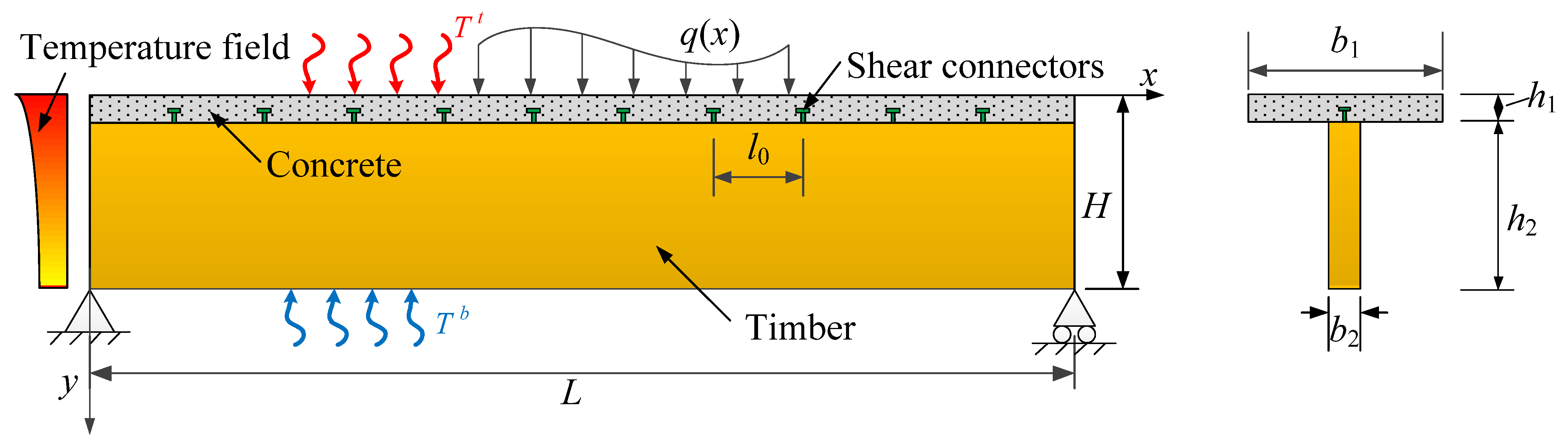
2. Analytical Model
2.1. Assumptions and Applicable Conditions
- (1)
- The mechanical property of the TCC beam is within the linear elastic range;
- (2)
- The absolute temperature considered is less than 100 °C and only the thermal deformation and stress are taken into account, while the ultra-high temperature, which leads to fire or material property change, is out of the scope of the present study;
- (3)
- The shear lag effect of the concrete flange is neglected.
2.2. Temperature Field
2.3. Stresses and Displacements under Thermo-Mechanical Load
3. Results and Discussion
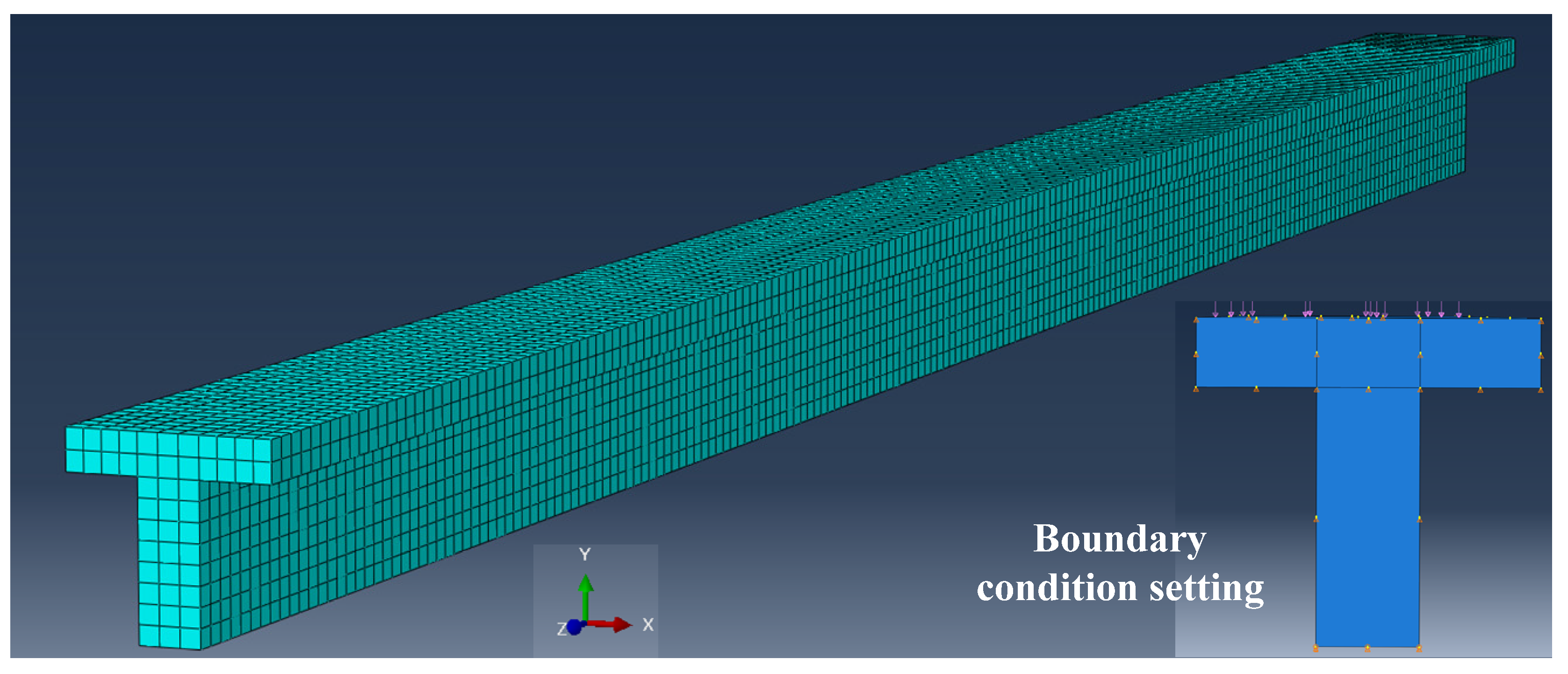
3.1. Comparison Analysis
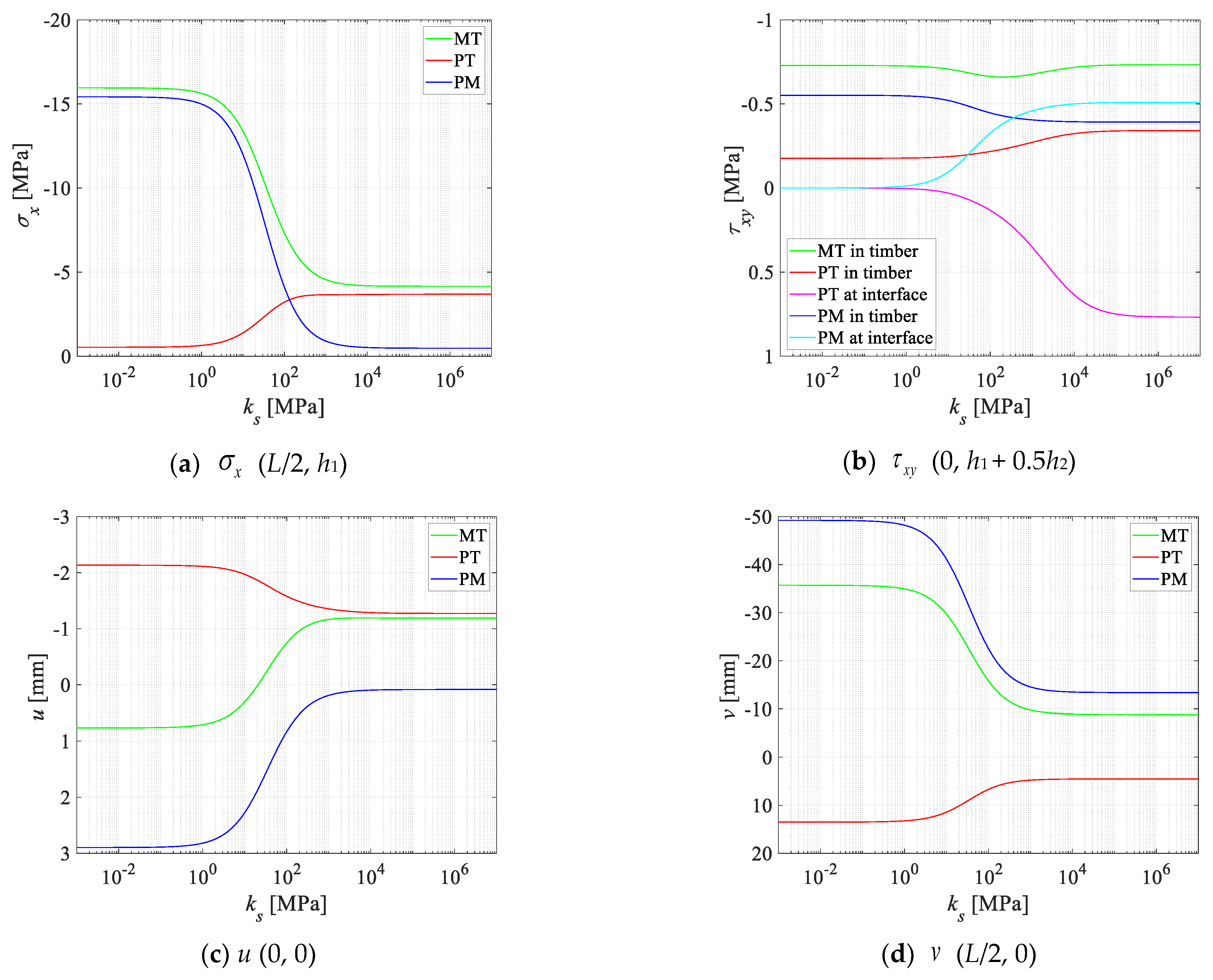
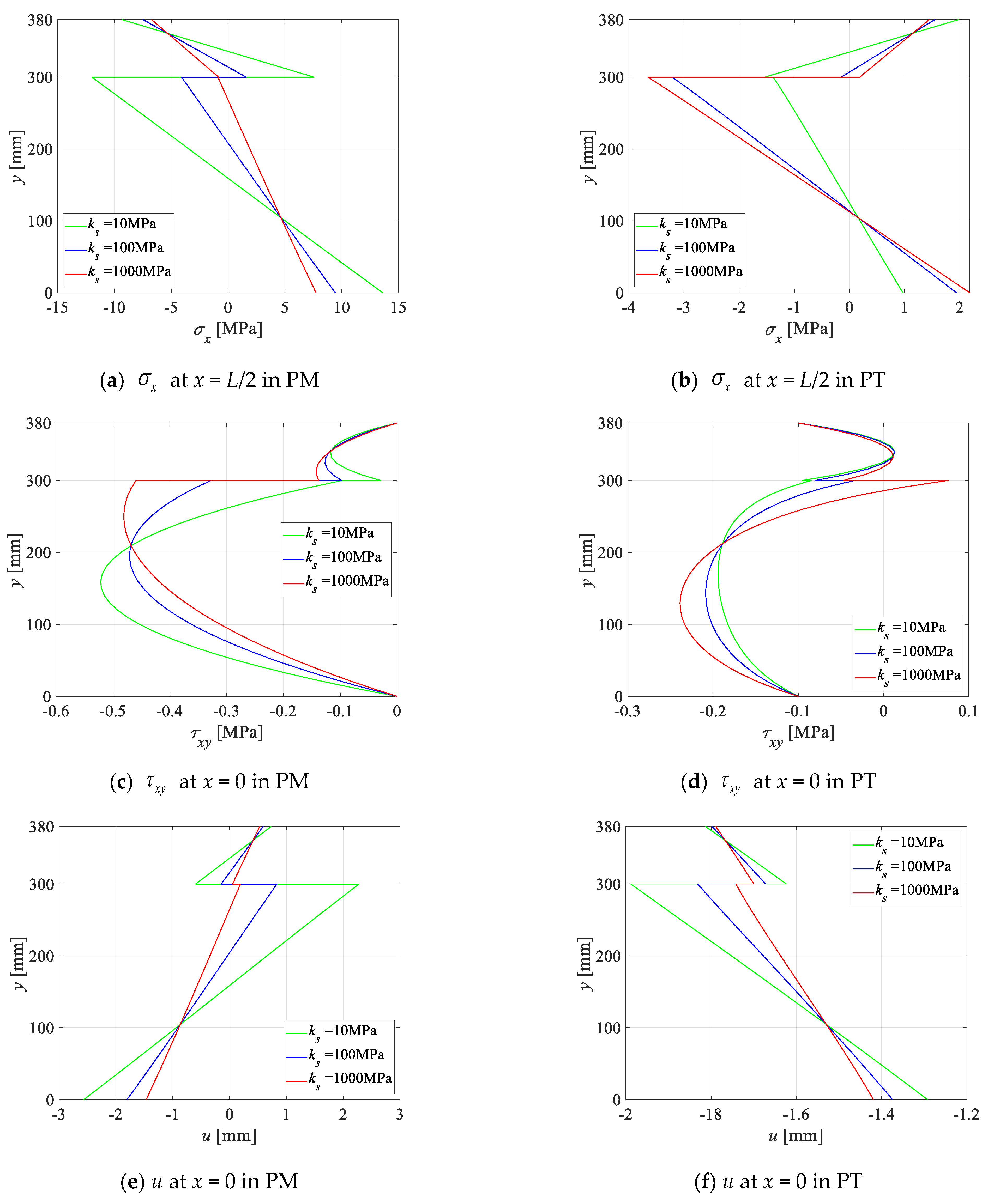
3.2. Parameter Analysis
4. Conclusions
- The proposed solution is in good agreement with the finite element result and offers higher accuracy compared to the simplified Euler–Bernoulli theory-based solution, which neglects the transverse shear deformation and the orthotropy of the TCC beam.
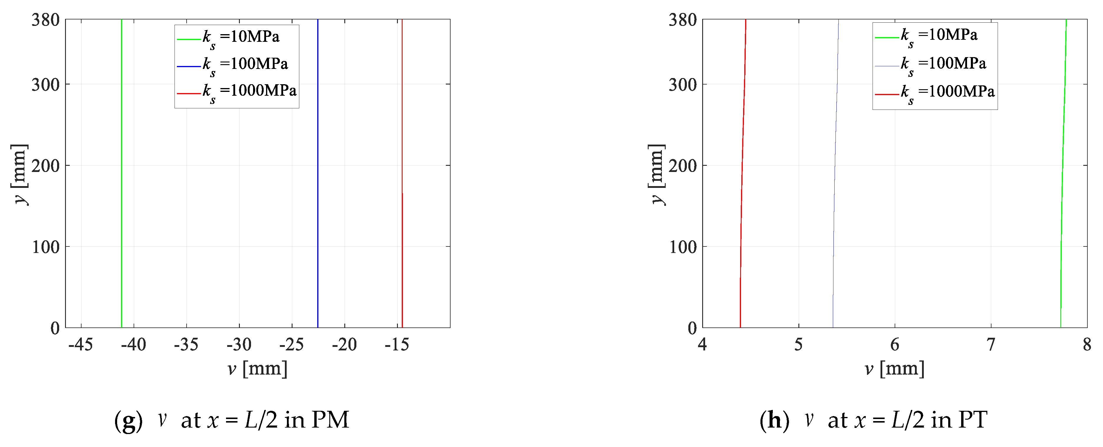
- The stresses and displacements vary with interfacial shear stiffness only in a certain range and remain constant in the rest ranges, which are actually no connection and perfect connection limits. The variations in the stresses and displacements under the pure thermal condition are opposite to those observed under pure mechanical loading. At the interface, with the increasing interfacial shear stiffness, the shear stress under pure mechanical and pure thermal conditions both increase, but the stress directions are opposite. The superposition principle is suitable for the stresses and displacements of the TCC beam under the thermo-mechanical condition.
- The stresses decrease with interfacial shear stiffness for the pure mechanical condition but have the opposite change law for the pure thermal condition. On the contrary, the displacements have the same change law. This is because for the TCC beam in the PM condition, the concrete and the timber parts resist the external mechanical load together, and as the combination effect increases, the stresses decrease. On the contrary, for the PT condition, the concrete and the timber parts resist each other because of the difference in thermal deformation. As the interfacial shear stiffness increases, the resistance effect becomes obvious and this leads to the stresses in the PT condition enlarging. The different mechanisms of the TCC beam from the PM and PT conditions are important for practical engineering. For a good design of the TCC beam under the thermo-mechanical condition, the stresses and displacements respectively from the PM and PT conditions can be partly offset in order to reduce the overall deflection or maximum stress.
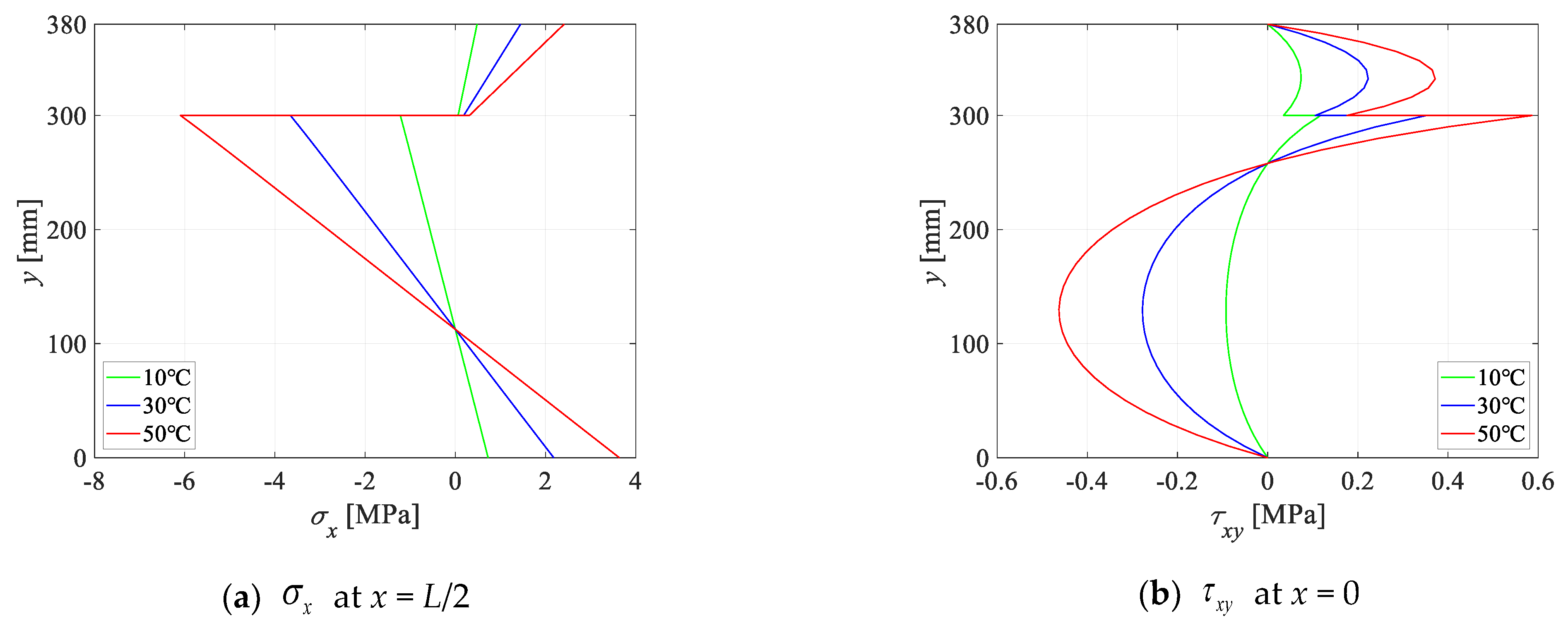
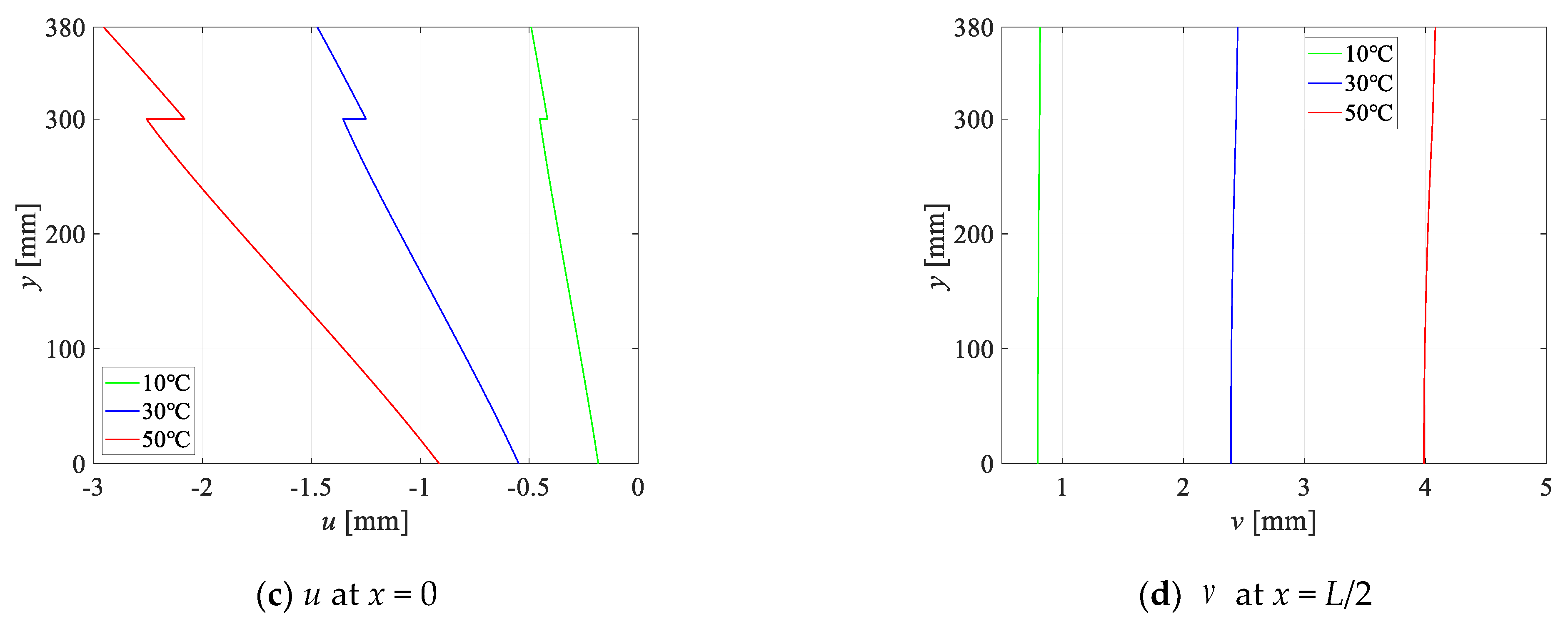
- The stress and displacement levels elevate as the surface temperature difference increases, mainly because of the distinct thermal expansion rates between concrete and timber. Additionally, the highest stress values manifest at the timber–concrete interface due to disparities in the material characteristics.
Author Contributions
Funding
Data Availability Statement
Conflicts of Interest
Appendix A
References
- Ling, Z.; Li, Z.; Lu, F.; Yang, H.; Zheng, W.; Zhang, L. Flexural strengthening of timber-concrete composite beams using mechanically fastened and externally bonded combining mechanically fastened strengthening techniques. J. Build. Eng. 2023, 78, 107645. [Google Scholar] [CrossRef]
- Tao, H.; Yang, H.; Zhang, J.; Ju, G.; Xu, J.; Shi, B. Nonlinear finite element analysis on timber-concrete composite beams. J. Build. Eng. 2022, 51, 104259. [Google Scholar] [CrossRef]
- Shi, B.; Liu, W.; Yang, H. Experimental investigation on the long-term behavior of prefabricated timber-concrete composite beams with steel plate connections. Constr. Build. Mater. 2021, 266, 120892. [Google Scholar] [CrossRef] [PubMed]
- Nero, R.; Christopher, P.; Ngo, T. Investigation of rolling shear properties of cross-laminated timber (CLT) and comparison of experimental approaches. Constr. Build. Mater. 2022, 316, 125897. [Google Scholar] [CrossRef]
- Li, C.; Li, S.-C.; Yue, K.; Wu, P.; Xiao, Z.-P.; Zhang, J. Analytical solutions and optimization design for bending behavior of cross-laminated timber beams considering orthotropy and interface slip. Case Stud. Constr. Mater. 2023, 18, e01948. [Google Scholar] [CrossRef]
- Piloto, P.A.G.; Fonseca, E.M.; Silva, L.; Leite, P.A. Numerical model to predict the effect of wood density in wood–steel–wood connections with and without passive protection under fire. J. Fire Sci. 2020, 38, 122–135. [Google Scholar]
- Gomes, C.; Fonseca, E.M.M.; Lopes, H.M. Thermomechanical Analysis of Steel-to-Timber Connections under Fire and the Material Density Effect. Appl. Sci. 2022, 12, 10516. [Google Scholar] [CrossRef]
- Du, H.; Hu, X.; Xie, Z.; Meng, Y. Experimental and analytical investigation on fire resistance of glulam-concrete composite beams. J. Build. Eng. 2021, 44, 103244. [Google Scholar] [CrossRef]
- Meena, R.; Schollmayer, M.; Tannert, T. Experimental and Numerical Investigations of Fire Resistance of Novel Timber-Concrete-Composite Decks. J. Perform. Constr. Facil. 2014, 28, A4014009. [Google Scholar] [CrossRef]
- Lange, D.; Boström, L.; Schmid, J.; Albrektsson, J. The Reduced Cross Section Method Applied to Glulam Timber Exposed to Non-standard Fire Curves. Fire Technol. 2015, 51, 1311–1340. [Google Scholar] [CrossRef]
- Le, T.D.H.; Tsai, M.-T. Experimental Assessment of the Fire Resistance Mechanisms of Timber–Steel Composites. Materials 2019, 12, 4003. [Google Scholar] [CrossRef]
- Liu, J.; Fischer, E.C.; Barbosa, A.R.; Sinha, A. Experimental Testing and Numerical Simulation of Timber-Concrete Composite Floors in Fire. J. Struct. Eng. 2023, 149, 04023151. [Google Scholar] [CrossRef]
- Zhang, Y.; Wang, L. Energy-based time equivalent method for evaluating the fire resistance of timber–concrete composite structures exposed to travelling fires. Struct. Infrastruct. Eng. 2022. [Google Scholar] [CrossRef]
- Dellepiani, M.G.; Munoz, G.R.; Yanez, S.J.; Guzmán, C.F.; Flores, E.I.S.; Pina, J.C. Numerical study of the thermo-mechanical behavior of steel-timber structures exposed to fire. J. Build. Eng. 2023, 65, 105758. [Google Scholar] [CrossRef]
- Laranjeira, J.P.D.; Cruz, H.; Pinto, A.P.F.; dos Santos, C.P.; Pereira, J.F. Reaction to Fire of Existing Timber Elements Protected with Fire Retardant Treatments: Experimental Assessment. Int. J. Archit. Herit. 2015, 9, 866–882. [Google Scholar] [CrossRef]
- Qin, R.; Zhou, A.; Chow, C.L.; Lau, D. Structural performance and charring of loaded wood under fire. Eng. Struct. 2021, 228, 111491. [Google Scholar] [CrossRef]
- Shi, D.; Hu, X.; Du, H.; Meng, Y.; Xie, Z. Thermo-mechanical analysis on shear behavior of grooved connectors for glulam-concrete composite beams under fire. Fire Saf. J. 2022, 130, 103594. [Google Scholar] [CrossRef]
- Hehl, S.; Tannert, T.; Meena, R.; Vallee, T. Experimental and Numerical Investigations of Groove Connections for a Novel Timber-Concrete-Composite System. J. Perform. Constr. Facil. 2014, 28, A4014010. [Google Scholar] [CrossRef]
- Djoubissie, D.D.; Messan, A.; Fournely, E.; Bouchaïr, A. Experimental study of the mechanical behavior of timber-concrete shear connections with threaded reinforcing bars. Eng. Struct. 2018, 172, 997–1010. [Google Scholar] [CrossRef]
- Siddika, A.; Mamun, M.A.A.; Aslani, F.; Zhuge, Y.; Alyousef, R.; Hajimohammadi, A. Cross-laminated timber–concrete composite structural floor system: A state-of-the-art review. Eng. Fail. Anal. 2021, 130, 105766. [Google Scholar] [CrossRef]
- Mirdad, M.A.H.; Chui, Y.H.; Tomlinson, D. Capacity and Failure-Mode Prediction of Mass Timber Panel–Concrete Composite Floor System with Mechanical Connectors. J. Struct. Eng. 2021, 147, 04020338. [Google Scholar] [CrossRef]
- Shi, B.; Zhu, W.; Yang, H.; Liu, W.; Tao, H.; Ling, Z. Experimental and theoretical investigation of prefabricated timber-concrete composite beams with and without prestress. Eng. Struct. 2020, 204, 109901. [Google Scholar] [CrossRef]
- Zhang, L.; Zhou, J.; Zhang, S.; Chui, Y.H. Bending stiffness prediction to mass timber panel-concrete composite floors with notched connections. Eng. Struct. 2022, 262, 114354. [Google Scholar] [CrossRef]
- Sebastian, W.M.; Bell, O.G.A.; Martins, C.; Dias, A.M.P.G. Experimental evidence for effective flexural-only stiffnesses to account for nonlinear flexural-slip behavior of timber-concrete composite sections. Constr. Build. Mater. 2017, 149, 481–496. [Google Scholar] [CrossRef]
- Ishaquddin, M.S. Gopalakrishnan. Differential quadrature-based solution for non-classical Euler-Bernoulli beam theory. Eur. J. Mech. A/Solids 2021, 86, 104135. [Google Scholar] [CrossRef]
- Cannizzaro, F.; Fiore, I.; Caddemi, S.; Caliò, I. The exact distributional model for free vibrations of shear-bending multi-cracked Timoshenko beams. Eur. J. Mech. A/Solids 2023, 101, 105039. [Google Scholar] [CrossRef]
- Gorik, A.V. Theoretical and experimental deformation parameters of composite beams with account of deplanation of cross sections in bending. Mech. Compos. Mater. 2003, 39, 57–64. [Google Scholar] [CrossRef]
- Matsunaga, H. Interlaminar stress analysis of laminated composite beams according to global higher-order deformation theories. Compos. Struct. 2002, 34, 105–114. [Google Scholar] [CrossRef]
- Piskunov, V.G.; Grinevitskii, B.V. Variant of an analytical shear model for the stress-strain state of heterogeneous composite beams. Mech. Compos. Mater. 2004, 40, 409–417. [Google Scholar] [CrossRef]
- Yang, Z.; Zhu, H.; Yu, F.; Wu, P.; Fang, H. Thermo-mechanical coupled behavior of laminated beams with temperature-dependent viscoelastic interlayers. Eur. J. Mech. A/Solids 2023, 100, 105000. [Google Scholar] [CrossRef]
- Zhang, Z.; Sun, Y.; Xiang, Z.; Qian, W.; Shao, X. Transient Thermoelastic Analysis of Rectangular Plates with Time-Dependent Convection and Radiation Boundaries. Buildings 2023, 13, 2147. [Google Scholar] [CrossRef]
- Zhang, Z.; Zhou, D.; Zhang, J.; Fang, H.; Han, H. Transient analysis of layered beams subjected to steady heat supply and mechanical load. Steel Compos. Struct. 2021, 40, 87–100. [Google Scholar]
- Li, X.; Wu, P.; Fang, H.; Wang, J.; Yu, Y. 3D viscoelastic solutions for bending creep of layered rectangular plates under time-varying load. Compos. Struct. 2023, 325, 117590. [Google Scholar] [CrossRef]
- Yu, F.; Guan, B.; Wu, P.; Fang, H.; Gu, Z. Long-term behavior of multilayered angle-ply plate structures with viscoelastic interlayer by state space method. Thin Walled Struct. 2022, 171, 108766. [Google Scholar] [CrossRef]
- Guan, B.; Xu, T.; Yue, K.; Deng, W.; Wu, P.; Zhang, J. Exact solution and case studies for composite I-beam with corrugated steel web. Case Stud. Constr. Mater. 2023, 19, e02422. [Google Scholar] [CrossRef]
- Loehrmann, J. Wood Handbook: Wood as an Engineering Material; Departament of Agriculture: Washington, DC, USA, 1999; pp. 53–101. [Google Scholar]
- Girhammar, U.A.; Gopu, V.K.A. Composite beam-columns with interlayer slip-exact analysis. J. Struct. Eng. 1993, 119, 1265–1282. [Google Scholar] [CrossRef]
- Tao, H.; Shi, B.; Yang, H.; Wang, C.; Ling, X.; Xu, J. Experimental and finite element studies of prefabricated timber-concrete composite structures with glued perforated steel plate connections. Eng. Struct. 2022, 268, 114778. [Google Scholar] [CrossRef]


| L/H | Solution | Proposed | FE | EB | Error of FE | Error of EB |
|---|---|---|---|---|---|---|
| 20 | [MPa] | 13.56 | 13.80 | 13.27 | 1.77% | 2.14% |
| [MPa] | −0.7418 | −0.7564 | −0.7720 | 1.97% | 4.07% | |
| v [mm] | −21.94 | −22.46 | −22.41 | 2.38% | 2.14% | |
| 15 | [MPa] | 7.669 | 7.781 | 7.465 | 1.46% | 2.66% |
| [MPa] | −0.5478 | −0.5599 | −0.5790 | 2.20% | 5.70% | |
| v [mm] | −7.316 | −7.390 | −7.092 | 1.01% | 3.06% | |
| 10 | [MPa] | 3.459 | 3.499 | 3.318 | 1.16% | 4.08% |
| [MPa] | −0.3533 | −0.3631 | −0.3860 | 2.78% | 9.26% | |
| v [mm] | −1.654 | −1.680 | −1.401 | 1.57% | 15.3% | |
| 5 | [MPa] | 0.928 | 0.9506 | 0.8294 | 2.44% | 10.6% |
| [MPa] | −0.1587 | −0.1623 | −0.1930 | 2.26% | 21.6% | |
| v [mm] | −0.1692 | −0.1730 | −0.08756 | 2.24% | 48.3% |
Disclaimer/Publisher’s Note: The statements, opinions and data contained in all publications are solely those of the individual author(s) and contributor(s) and not of MDPI and/or the editor(s). MDPI and/or the editor(s) disclaim responsibility for any injury to people or property resulting from any ideas, methods, instructions or products referred to in the content. |
© 2023 by the authors. Licensee MDPI, Basel, Switzerland. This article is an open access article distributed under the terms and conditions of the Creative Commons Attribution (CC BY) license (https://creativecommons.org/licenses/by/4.0/).
Share and Cite
Guan, B.; Dai, Y.; Zhang, T.; Wu, P.; Zhang, J. Theoretical Analysis on Thermo-Mechanical Bending Behavior of Timber–Concrete Composite Beams. Buildings 2023, 13, 3101. https://doi.org/10.3390/buildings13123101
Guan B, Dai Y, Zhang T, Wu P, Zhang J. Theoretical Analysis on Thermo-Mechanical Bending Behavior of Timber–Concrete Composite Beams. Buildings. 2023; 13(12):3101. https://doi.org/10.3390/buildings13123101
Chicago/Turabian StyleGuan, Bin, Yunchun Dai, Tianyi Zhang, Peng Wu, and Jiandong Zhang. 2023. "Theoretical Analysis on Thermo-Mechanical Bending Behavior of Timber–Concrete Composite Beams" Buildings 13, no. 12: 3101. https://doi.org/10.3390/buildings13123101