1. Introduction
In recent years, with the rapid development of the global economy, high-rise and super-high-rise buildings have been growing at a fast pace. In the construction of the main structures of high-rise and super-high-rise buildings, traditional construction methods include scaffold formwork technology [
1,
2,
3], hydraulic climbing formwork technology [
3,
4,
5,
6,
7,
8], sliding formwork technology [
8,
9,
10], attached lifting scaffold technology [
11], low-level formwork technology [
12,
13], and so on. However, these traditional construction methods commonly face issues such as relatively outdated technology, high construction safety risks, poor working environments, and low construction efficiency.
To address these problems, China Construction Third Engineering Bureau has independently developed an innovative piece of construction equipment for high-rise buildings, known as the High-Rise Building Integrated Operation Construction Platform (commonly referred to as the “Building Machine”) [
14]. The building machine is a specialized piece of equipment for high-rise building construction, developed collaboratively by professionals in electrical, mechanical, and civil engineering fields. Its purpose is to enhance the efficiency and safety of high-rise construction. This equipment utilizes a support system to achieve overall elevation, effectively serving as a mobile aerial factory. Compared to traditional construction techniques, building machine has rapidly evolved in the field of high-rise building construction, significantly improving construction efficiency. It boasts strong integration and comprehensiveness, while demonstrating efficient intelligence, versatility, and multi-work coordination in construction operations [
15,
16,
17,
18]. This enhances construction safety and meets the personalized needs of the operators, effectively compensating for the deficiencies of traditional high-rise building main structure construction techniques. The emergence of the building machine not only addresses the shortcomings in traditional construction techniques for the primary structures of high-rise buildings but also provides favorable construction technology and conditions for achieving Sustainable Development Goal 11, as outlined by the United Nations. This goal specifically pertains to the construction of inclusive, safe, disaster-resistant, and sustainable cities and human settlements [
19].
However, the design and layout of traditional building machines typically rely on two-dimensional design methods [
20,
21]. This approach involves manual drawing and adjustments, consuming significant time and effort. Traditional two-dimensional design methods in building machine design reveal a series of challenges, including, but not limited to, accurately expressing the complexity of building machines. Moreover, with the increasing number of high-rise buildings in China, there is a growing demand for building machines in the construction industry. However, due to variations in design requirements, building structures, and working environments among different projects, the shape and layout of building machines need personalized design based on specific projects. However, two-dimensional design provides only flat drawings, lacking a sense of three-dimensionality and spatial perception. This limitation makes it difficult to comprehensively consider the three-dimensional effects and interactive operations between building machines and structures during the design phase [
16]. As a result, building machines may deviate from expectations, requiring subsequent adjustments and modifications, thereby increasing time and cost expenditures. Despite past contributions in the field of mechanical design, previous two-dimensional design methods exhibit limitations when addressing the unique challenges of building machine design. Prior research often falls short in effectively addressing the three-dimensional representation of mechanical structures, potentially leading to inaccuracies and inefficiencies in practical applications.
To address these issues, there is an urgent need for a more flexible and comprehensive design approach. Therefore, this study aims to explore and promote the application of three-dimensional parametric design in building machine design to enhance precision and efficiency in the design process; to achieve this, this study introduces the concept of parametric three-dimensional design. Parametric three-dimensional design employs parametric modeling techniques, transforming the design process into parameter-based model generation. This approach allows designers to rapidly create building machine models of various shapes and sizes by adjusting parameter values, thereby expediting the design process in terms of speed and flexibility. Compared to traditional two-dimensional design, parametric three-dimensional design more accurately captures the three-dimensional characteristics of buildings and provides more intuitive visual effects during the design process [
22].
Parametric design methods primarily include object-oriented programming, visual programming, functional programming, and distributed visual programming [
23]. BIM parametric design contributes to optimizing collaborative design methods and improving design efficiency [
24]. Through parametric design, multiple design proposals can be rapidly generated, compared, and analyzed. Parametric design is the most significant characteristic of BIM, as it can transform design concepts into parametric models [
25,
26]. This method makes the design process more intuitive while also enhancing flexibility and efficiency. Yang and others achieved full automation of structural parametric modeling, analysis, and optimization adjustments for super-high-rise building structures using Grasshopper software and genetic algorithms [
27]. Wang conducted research on the simulation of overall steel platform construction and the issue of asynchronous cylinder lifting displacement. They applied parametric modeling to the overall steel platform using Revit and simulated it in Navisworks, which has instructive implications for optimizing the performance of the overall steel platform [
28]. Li conducted parametric modeling and mechanical performance analysis of self-erecting platforms. Using parametric design methods, they rapidly generated the platform’s main body and various component parts, facilitating model modifications and expediting the design process [
29]. Geng conducted parametric modeling of self-elevating marine platforms using CAITA software. By employing parametric modeling principles, they established full-size constrained models of self-elevating marine platforms, greatly reducing the workload of design personnel. Additionally, the establishment of a knowledge repository allows design personnel to validate component dimensions without consulting specifications [
30]. Dong and others integrated parametric design with BIM and applied it in the Design for Manufacturability and Assembly (DFMA) domain. Their research outcomes are conducive to establishing standardized design and production systems for PC components, reducing design costs, and enhancing design efficiency [
31]. The aforementioned studies provide a robust theoretical foundation for parametric design of BMs. Additionally, Building Information Modeling (BIM) technology has a significant impact on the efficiency of high-rise building construction. Given the complexity of high-rise construction, various professionals need to collaborate closely throughout the entire project lifecycle. Research indicates that the use of BIM facilitates information exchange and resource coordination among teams, thereby enhancing collaboration in building projects [
32,
33]. BIM also allows for task coordination and project execution planning before construction begins. BIM models enable construction personnel to understand various requirements throughout the project lifecycle, aiding in appropriate construction preparations. For instance, BIM can be utilized for planning construction site traffic management and scheduling. BIM models are also employed for clash detection, preventing redundant work and delays on-site, ultimately improving construction efficiency.
The primary focus of this study is the rapid generation of building machine design and layout schemes based on parametric and virtual environment simulation methods, as well as the simulation of the operational process of the building machine. This research aims to improve the efficiency and cost issues associated with current construction practices and explore the adoption of BIM parametric building machine solutions. This approach is developed within the parametric modeling software environment of Blender, with a strong emphasis on the design phase. Furthermore, the study describes the simulation of building machine operations in a virtual environment to enhance design accuracy and productivity.
2. Research Background
Construction techniques play a crucial role in the field of civil engineering and architecture, and their continuous development is vital for meeting the ever-changing industry demands. Over the years, traditional construction methods have undergone significant improvements and have become mature practices in the field. Traditional construction techniques such as climbing formwork, slip form, and jump formwork have been widely employed in the construction of high-rise buildings, bridges, and other large-scale projects. These techniques have proven their effectiveness in terms of structural integrity, construction efficiency, and safety [
34].
However, with the rapid advancement of technology, the construction industry has witnessed the emergence of a new construction technique, namely, the High-Rise Building Integrated Operation Construction Platform. This equipment is commonly referred to as a “Building Machine”, as it integrates various construction tools and equipment, making the construction process more intelligent and holistic. building machines offer higher precision, productivity, and safety, addressing some of the limitations and challenges faced by traditional construction methods. The following table briefly presents the performance and pros and cons of traditional construction techniques and the new building machine technology in terms of construction processes, as shown in
Table 1. From the table, it is evident that traditional construction techniques exhibit numerous shortcomings compared to the new building machine technology in terms of construction safety, efficiency, sustainability, construction quality, and operability. For example, due to poor overall integrity, traditional construction techniques result in slower construction efficiency compared to the new building machine technology. While traditional construction techniques generally have mature systems and lower initial costs in the early stages, the new building machine technology demonstrates higher construction efficiency throughout the entire construction period, leading to better economic benefits.
2.1. Traditional Climbing Formwork, Jump Formwork Construction Methods
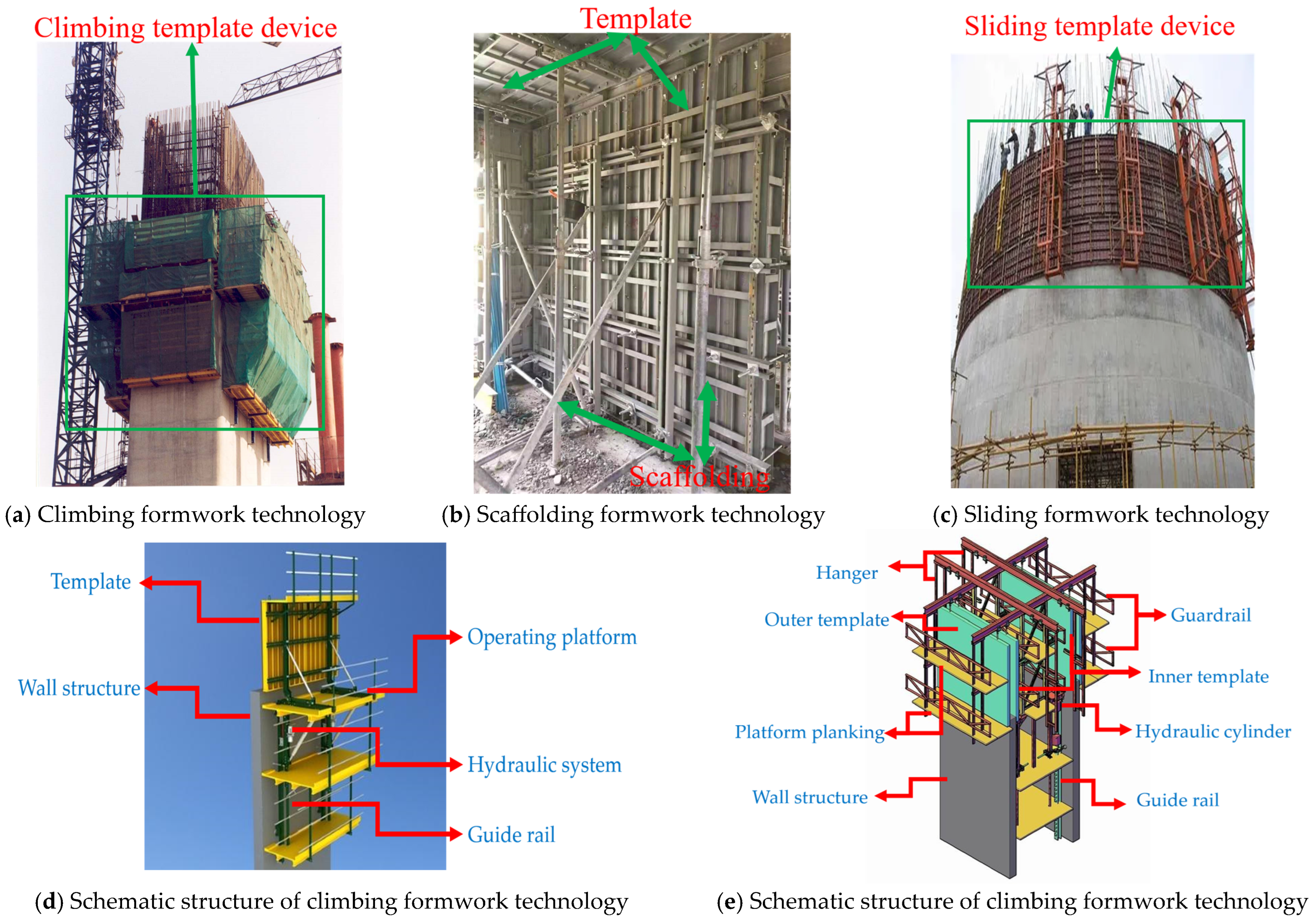
High-rise and super-high-rise buildings have been developed earlier in foreign countries, and correspondingly, the application of construction techniques is more extensive. Traditional high-rise construction techniques include scaffolding formwork technology, climbing formwork technology, and slipform technology, among others, as shown in
Figure 1. Scaffolding formwork technology was one of the early construction methods applied, known for its economic benefits and simplicity of operation [
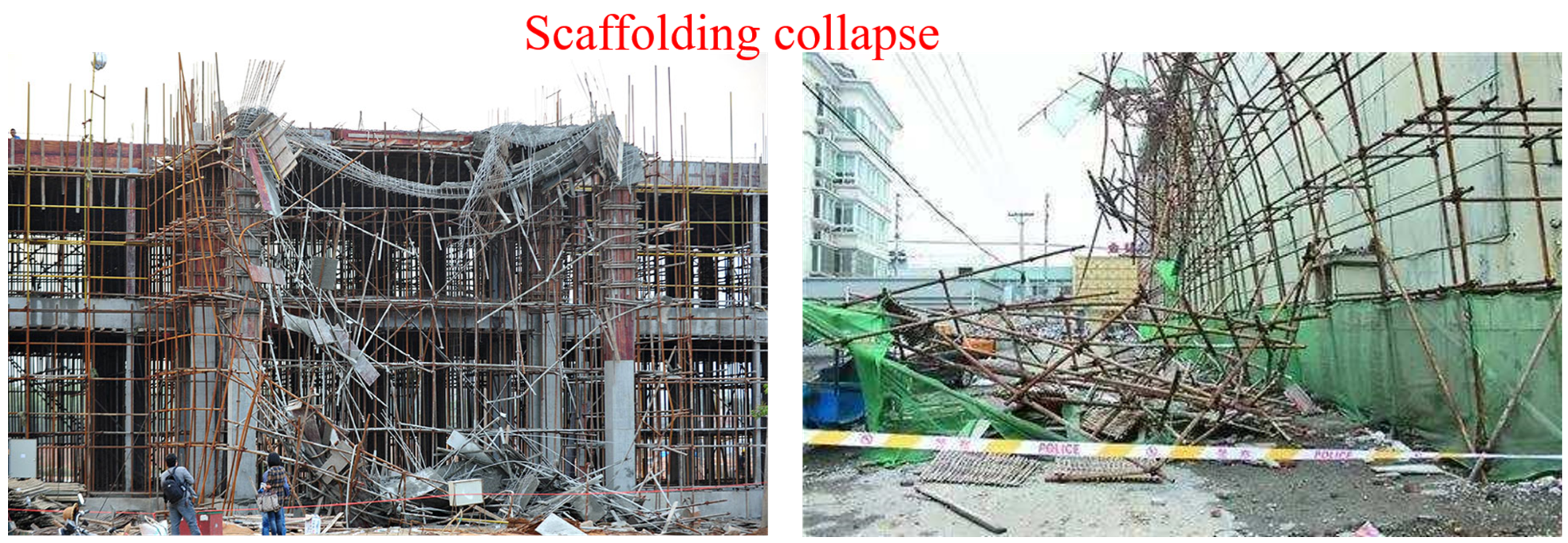
35]. However, the construction of scaffolding and formwork in a non-standard and unscientific manner, as well as issues related to quality, can lead to scaffold collapses. Currently, scaffold collapse accidents account for 30–50% of major construction accidents [
36,
37,
38,
39], as shown in
Figure 2. Climbing formwork technology is a product of the times, primarily consisting of large formwork, climbing frames, and power equipment. Although climbing formwork technology is straightforward to operate, convenient for construction, and does not require large machinery, it also faces several problems. The climbing formwork’s operating platform is cantilevered at both ends, serving as a distribution beam, making it prone to deformation during construction. Additionally, the climbing formwork structure is complex, and certain parts are prone to welding defects during factory processing. When subjected to uneven loads, welding defects can lead to failures [
5,
6,
8,
40,
41,
42,
43,
44]. Slipform technology is a common construction method for high-rise buildings, composed of three parts: the formwork device, lifting frame, and enclosure; the second part includes the main operating platform, upper auxiliary operating platform, and inner and outer suspension scaffolding; and the third part is hydraulic control and support rods. These three components work together to form the slipform technology construction platform [
10,
45,
46,
47]. However, during the construction process, uneven loading on support rods can lead to bending instability, and the load distribution on the operating platform is uncertain, potentially resulting in deviations in the jack’s lifting, which can cause the building to tilt.
In addition, well-known international scaffolding and formwork companies include DOKA from Austria, PERI and HÜNNEBECK from Germany, and RMD and SGB from the United Kingdom, among others [
48]. These companies have been committed to providing excellent construction equipment and solutions for traditional high-rise building techniques. Kim and colleagues developed a method for automatically planning scaffolding systems, facilitating management in BIM. Their research results demonstrated the successful generation of BIM models for scaffolding system loading, which can be used for communication, material costing, scheduling simulations, and as a benchmark for accurate on-site installation and performance measurement [
1]. Jin and others developed a BIM-based tool that integrates design, planning, and generation, streamlining the scaffolding and formwork design modeling process. The practicality of this tool was demonstrated through case applications [
49]. Chi and colleagues developed temporary support BIM objects, offering modular scaffolding and formwork to promote smarter and safer construction [
37]. Kim and colleagues proposed a novel table formwork method combined with a layout planning approach for high-rise building construction. The adjustable subunits of the formwork can adapt to different building shapes. In case studies, the proposed layout planning model not only provided lower costs but also improved work efficiency. Compared to heuristic methods, it could be completed in less time [
40]. Furthermore, Schmitt extensively discussed slip form and climbing formwork construction techniques in the foreign high-rise building construction sector and applied computer-aided techniques to formwork planning and design, providing wide-ranging applications for modern construction [
50].
2.2. New Building Machine Technology
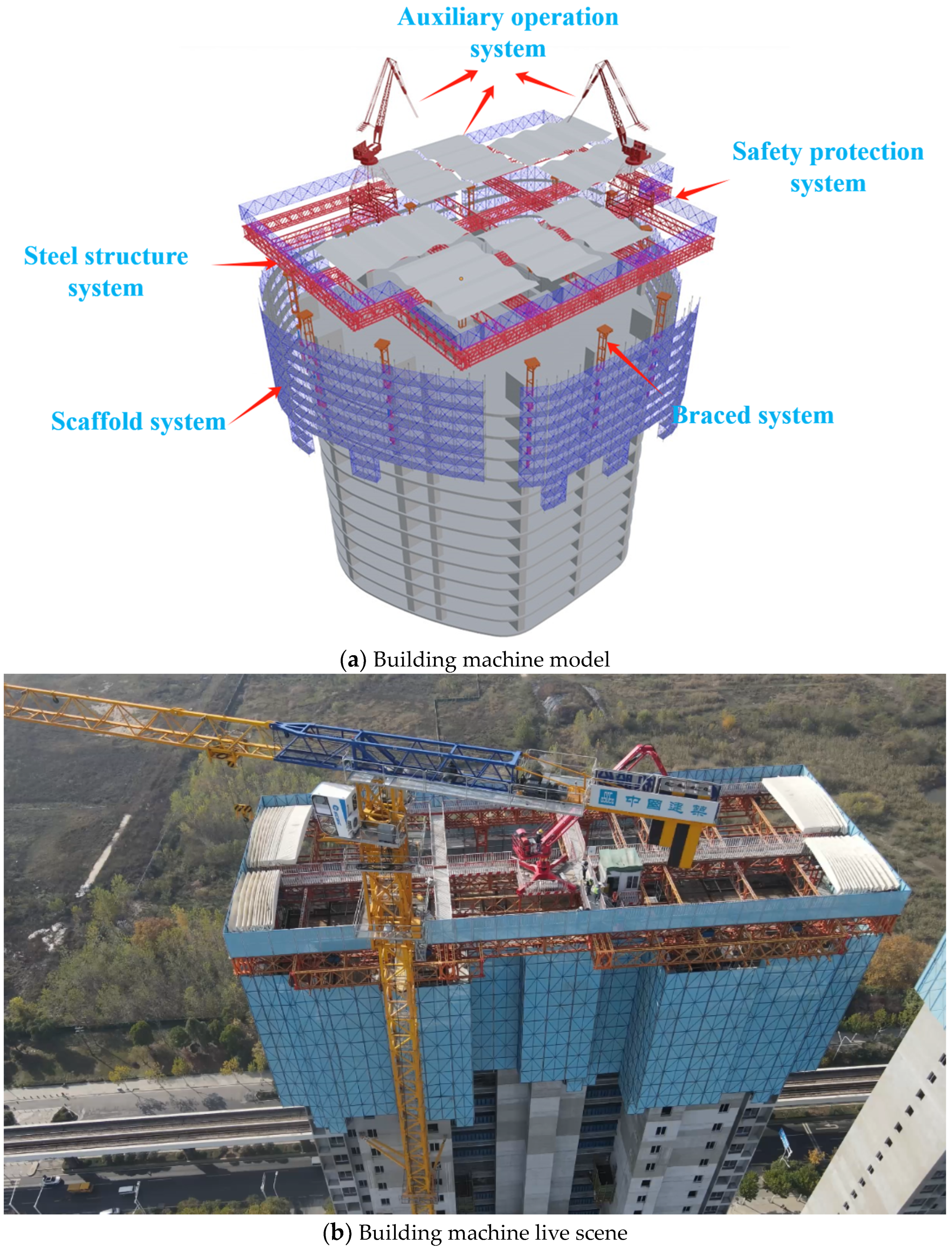
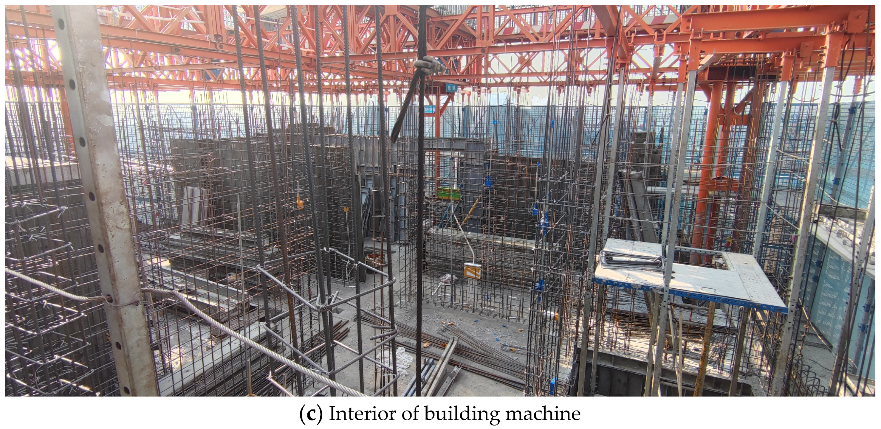
The aforementioned methods are common technical means for the construction of the core of super-high-rise buildings. While traditional technical means have their advantages, their shortcomings are also evident. The China Construction Third Engineering Bureau has developed an integrated construction platform for high-rise building construction, known as the building machine [
14]. This platform combines the advantages of the three types of construction platforms mentioned earlier and effectively addresses the issues associated with traditional construction techniques. The building machine is currently one of the most advanced construction equipment systems, suitable for high-rise buildings and high-rise residential structures. It offers advantages such as safety, efficiency, versatility, round-the-clock operation, and minimal construction machinery. Compared to traditional climbing systems, the building machine has the following advantages: it provides a humane, intelligent, three-dimensional construction platform, effectively enhancing the safety and engineering quality of high-rise building construction, and it achieves efficient interweaving of various processes, including secondary structures, interior decoration, and more, effectively reducing construction time by more than 20% [
14].
This platform consists of six major systems: the steel platform system, hanging frame system formwork system, safety protection system, lifting power system, and auxiliary operation system. It represents a new type of building-making technology [
15,
16], as shown in
Figure 3. The China Construction Third Engineering Bureau has accumulated decades of experience in high-rise and super-high-rise construction techniques. They have developed and applied a series of integrated platforms for super-high-rise construction, integrating the construction equipment and facilities required for multiple disciplines and processes into a single platform. This platform provides comprehensive services for formwork engineering, reinforcement engineering, steel structure installation, construction measurement, and more, enabling the “factory-like” construction of super-high-rise buildings.
Xu and others applied BIM technology to the design, CNC processing, assembly construction, and data-driven detection of residential building machines, simplifying complex spatial design and elevating the level of project precision management [
20]. Li and colleagues addressed the high cost and operational complexity of aerial building machines and proposed an innovative design for a lightweight integrated platform. They validated the feasibility, cost-effectiveness, and versatility of this design through the Wuhan Yangtze River Center project, providing a platform for future integration with smart equipment [
21]. Liao and others compared residential building machines with traditional climbing formwork construction methods and found that residential building machines have excellent versatility and clear advantages in terms of construction processes, the environment, and safety. They emphasized that the overall design of residential building machines is more user-friendly, providing a more comfortable and safe construction environment, which is a focus of future development in the construction industry. However, they also pointed out that the technology of residential building machines is not yet mature and has several issues, including the complexity of the installation process for building machines, immature rotation-use technology, and a lack of standardization, modularity, and intelligence. The studies mentioned above primarily apply BIM technology to the full-process design, construction, and operation of building machines in high-rise building construction [
16]. These research outcomes are applied to practical projects, effectively reducing construction complexity and shortening construction periods.
3. Materials and Methods
Today, in the field of architecture, there are many powerful design software tools, such as 2D design software CAD, and 3D design software like Revit, SketchUp, Rhino, and Blender. Revit, as a mainstream BIM software, has been widely used by designers since its inception, demonstrating clear advantages in areas such as architectural design and clash detection. However, it may have limitations in parametric modeling, freeform modeling, and rendering. SketchUp and Rhino excel in freeform modeling and architectural visualization. Rhino, in particular, comes with the Grasshopper plugin, a visual programming tool enabling robust parametric design. Blender is an open-source software that integrates 3D modeling, parametric modeling, rendering, animation, and more. Blender allows creators to write plugins according to their specific needs. Blender’s Geometry Nodes feature, similar to Rhino’s Grasshopper, facilitates visual programming through the connection of nodes. However, Geometry Nodes are simpler in parametric modeling and provide numerous interfaces for combining existing models.
In this study, computer-aided tools are used in two phases: 1. Utilizing Blender, a 3D modeling software, for research in parametric design. 2. Employing Unity, a game engine software, to simulate the operation of the building machine. Unity is a versatile, real-time 3D platform used for creating visual products and interactive virtual experiences. It allows interactive operation of the building machine through a client interface.
3.1. Parameterization of the Building Machine
The building machine comprises six major systems, 3092 components, and 12,000 parameters [
22]. The building machine consists of six major systems: the steel platform system, the hanging frame system, the formwork system, the safety protection system, the lifting power system, and the auxiliary operation system. The steel platform system is composed of the Belew frame and connecting components. The hanging frame system includes walkway boards, protective mesh panels, suspension rods, columns, connecting crossbars, and various connecting components. The formwork system is constructed with aluminum templates. The safety protection system comprises protective railings and mesh panels on the upper part of the steel platform system. The lifting power system consists of support columns. The auxiliary operation system includes equipment such as cloth machines. These systems interact with each other to form this large integrated equipment, as illustrated in
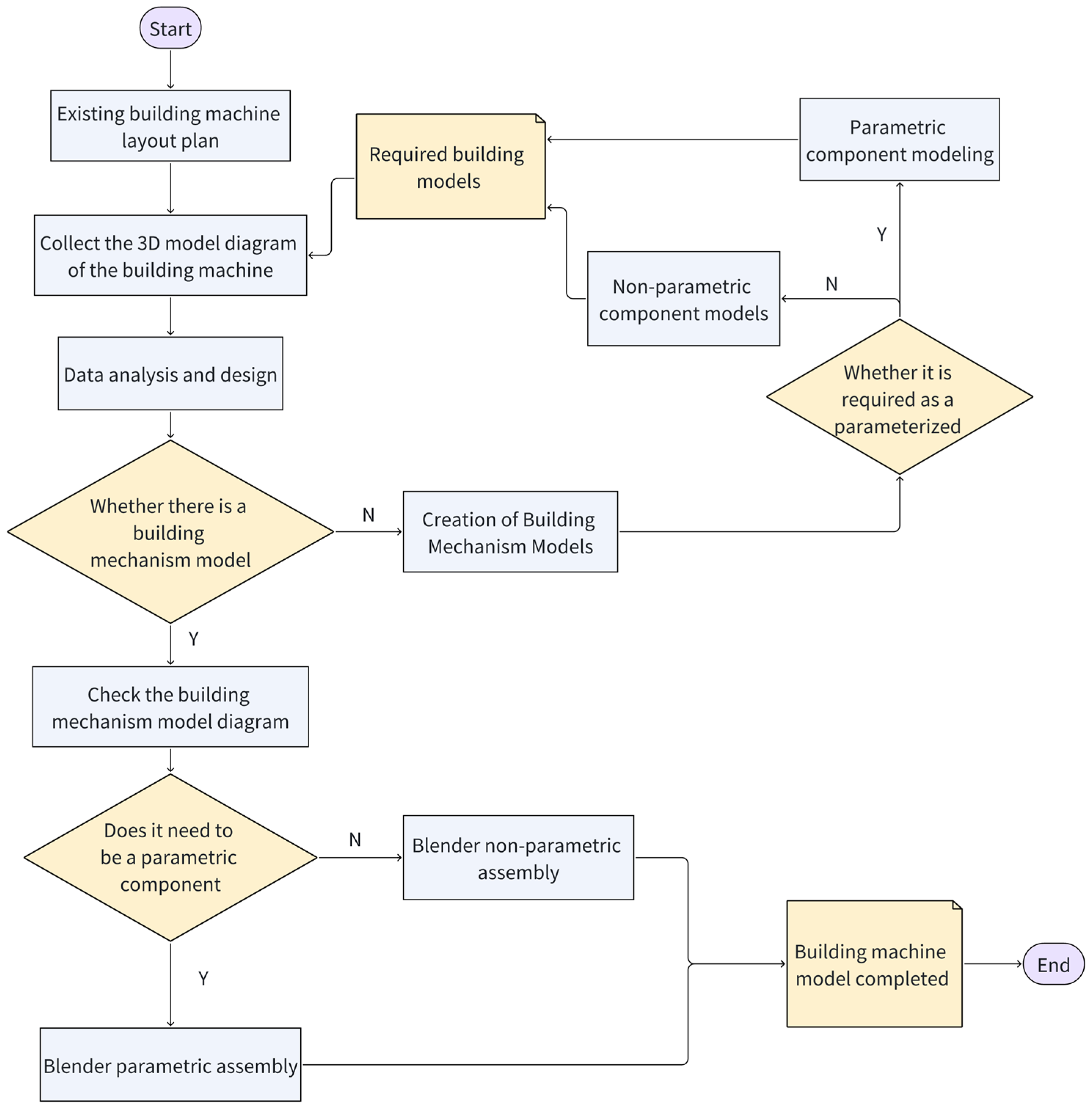
Table 2. To simplify the input conditions for the building machine and enable parametric design with the most streamlined elements, it is necessary to break down the machine into individual components. Parametric design should be carried out by first focusing on single components and then moving to multiple components, initially addressing the local aspects before considering the entire structure. This approach achieves block-level parameterization, improving modeling efficiency and preventing changes to individual parameters from affecting the coordination of other components. Additionally, the building machine consists of a combination of multiple systems forming construction equipment, and some system components have fixed models, not requiring parametric design. Only the variable components need a parametric design. The final step involves combining the parameterized components with the non-parameterized components to form the building machine.
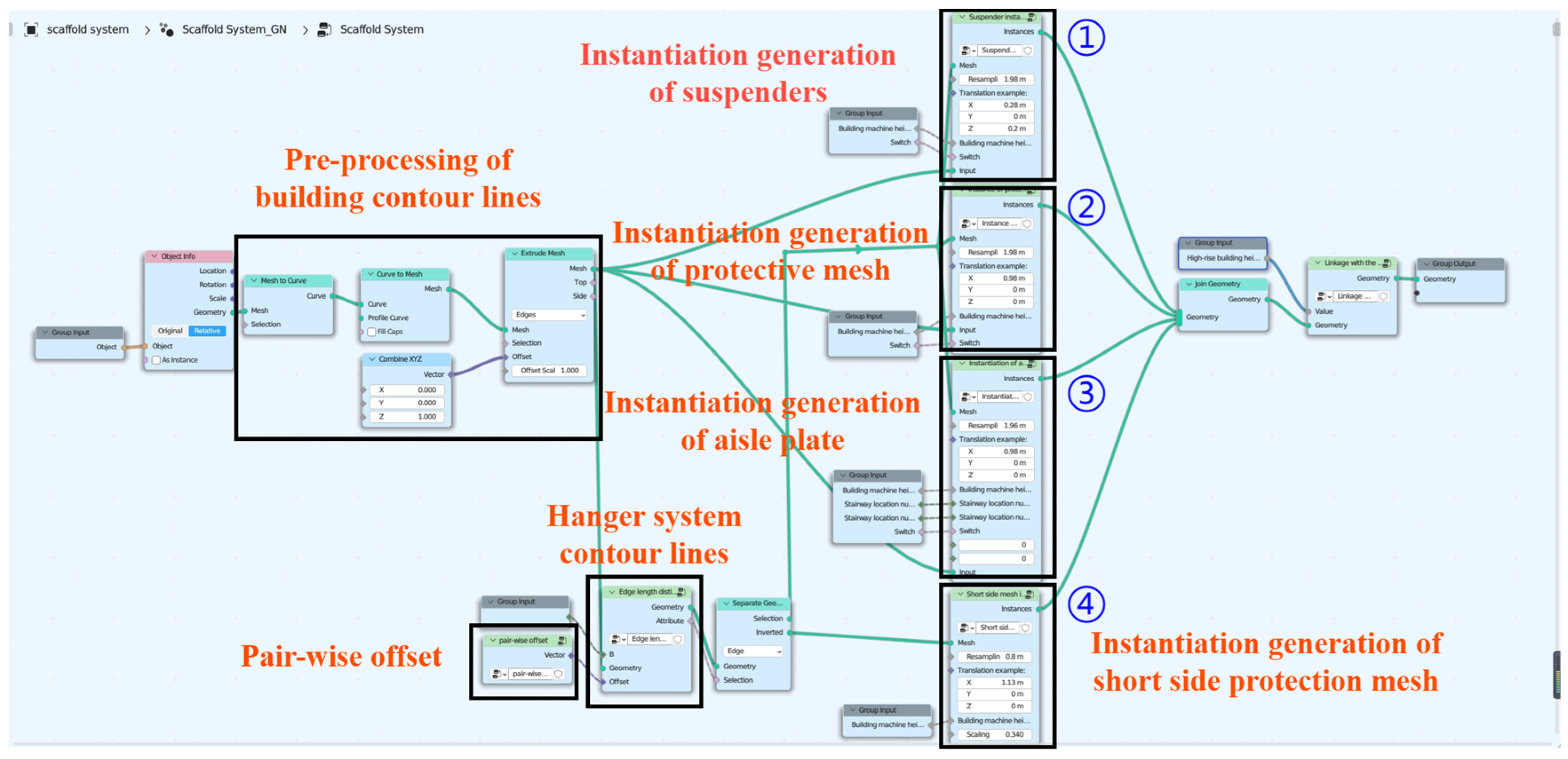
By categorizing the components of the construction crane system, due to the variety of components within the construction crane hanging system, emphasis is placed on the parametric design of this system. Step one: Begin by categorizing and organizing the components that require parametric modeling. Next, perform parametric modeling for this group of components, then conduct further parametric modeling for the assembled components, thereby completing the parametric modeling task. Step two: Initially, dissect the CAD structural drawing of the high-rise building project and extract the exterior outline of the architectural structure. Subsequently, import the CAD building outline into the Blender platform. Then, using Blender’s visual programming tool, Geometry Nodes, perform visual programming on this outline to generate the outline of the hanging system. Next, continue using visual programming methods to parametrically combine the components of the hanging system. Finally, achieve the automatic generation of the construction crane hanging system platform by selecting the building outline. Lastly, integrate this with the non-parametric part of the system to form a complete construction crane model, as shown in
Figure 4.
3.1.1. Parameterized Component Generation
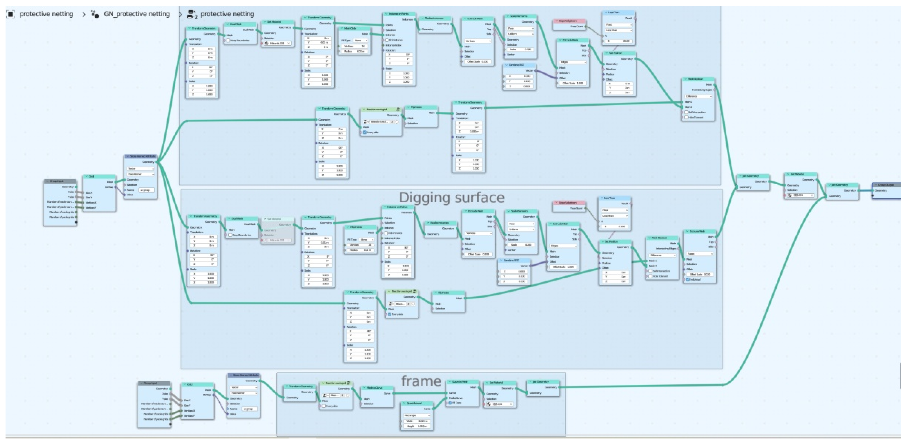
Since the lifting power system supporting columns and the type of steel platform Belej rack for the construction crane have already been determined, they do not require parametric design. However, the construction crane hanging system comprises components such as protective mesh, walkway panels, and connecting crossbars, among others. These components within the construction crane hanging system come in various types, and parametric modeling of these elements facilitates rapid generation and convenient utilization, thereby enhancing efficiency. Once individual components have been parametrically modeled, they are combined to achieve an overall parametric hanging system. The following will illustrate parametric component design modeling using protective mesh and walkway panels as examples.
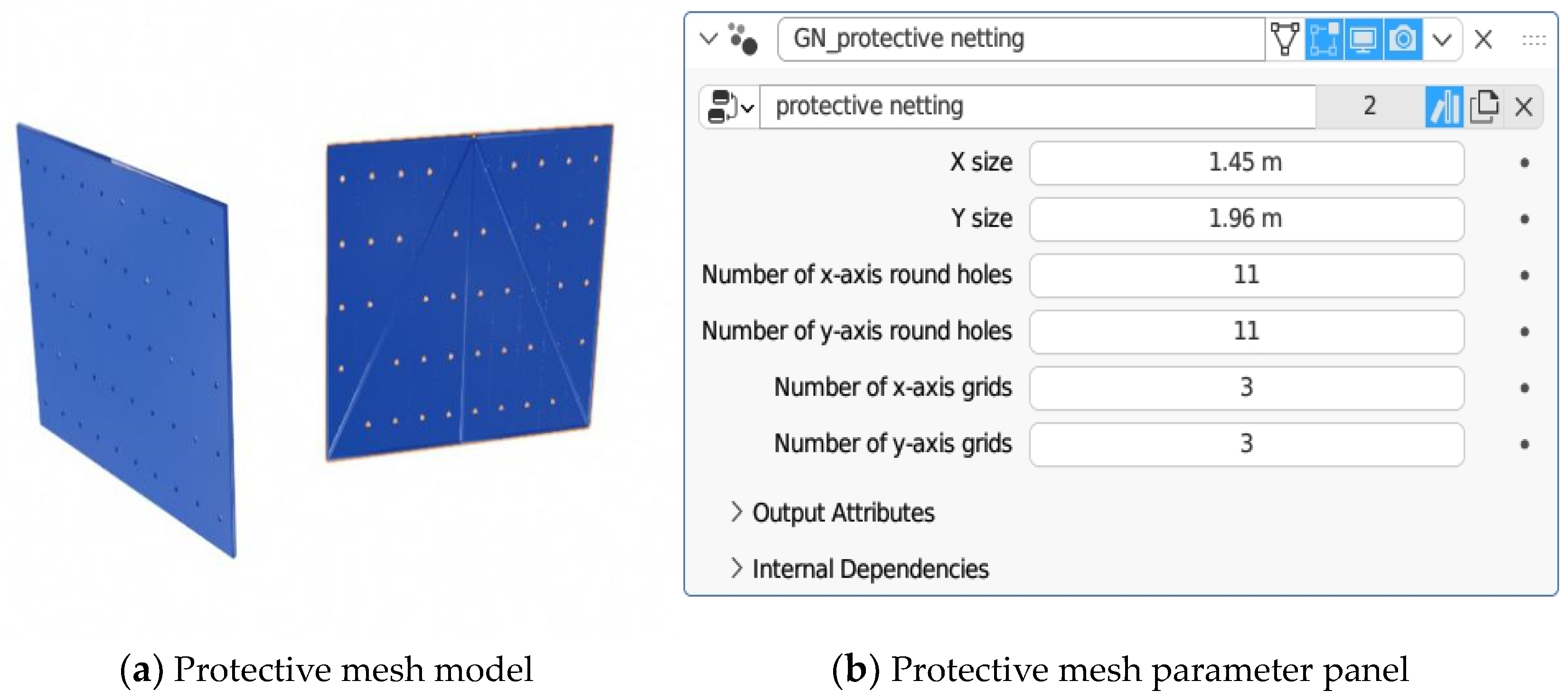
As a critical component within the hanging framework, the design of protective net panels is crucial to meet the safety requirements for construction personnel. Given the distinct nature of each project, the dimensions and types of these net panels vary accordingly during the setup of construction machinery. Leveraging parametric modeling in designing these protective net panels resolves complex issues related to production, processing, and assembly, particularly when dealing with diverse types.
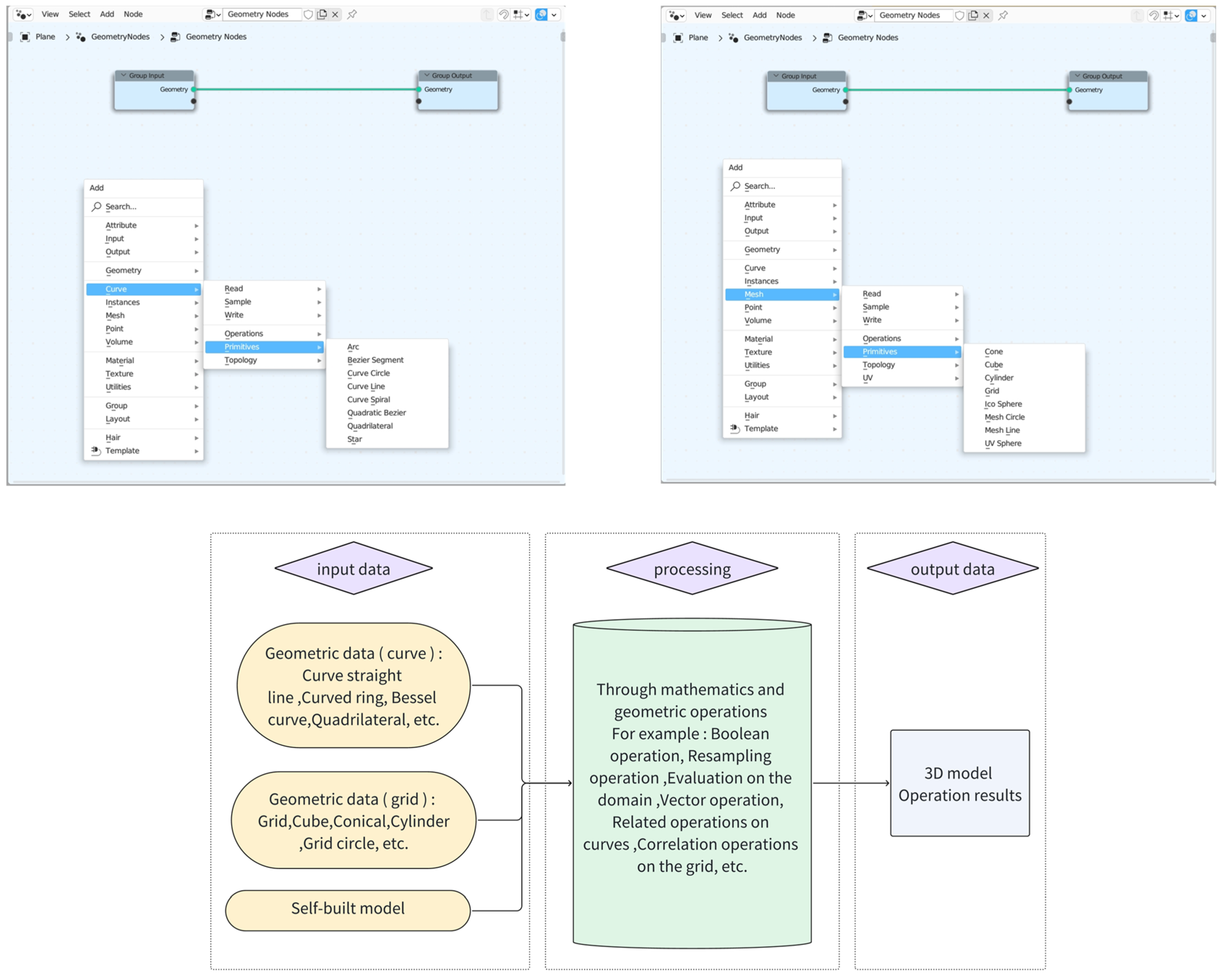
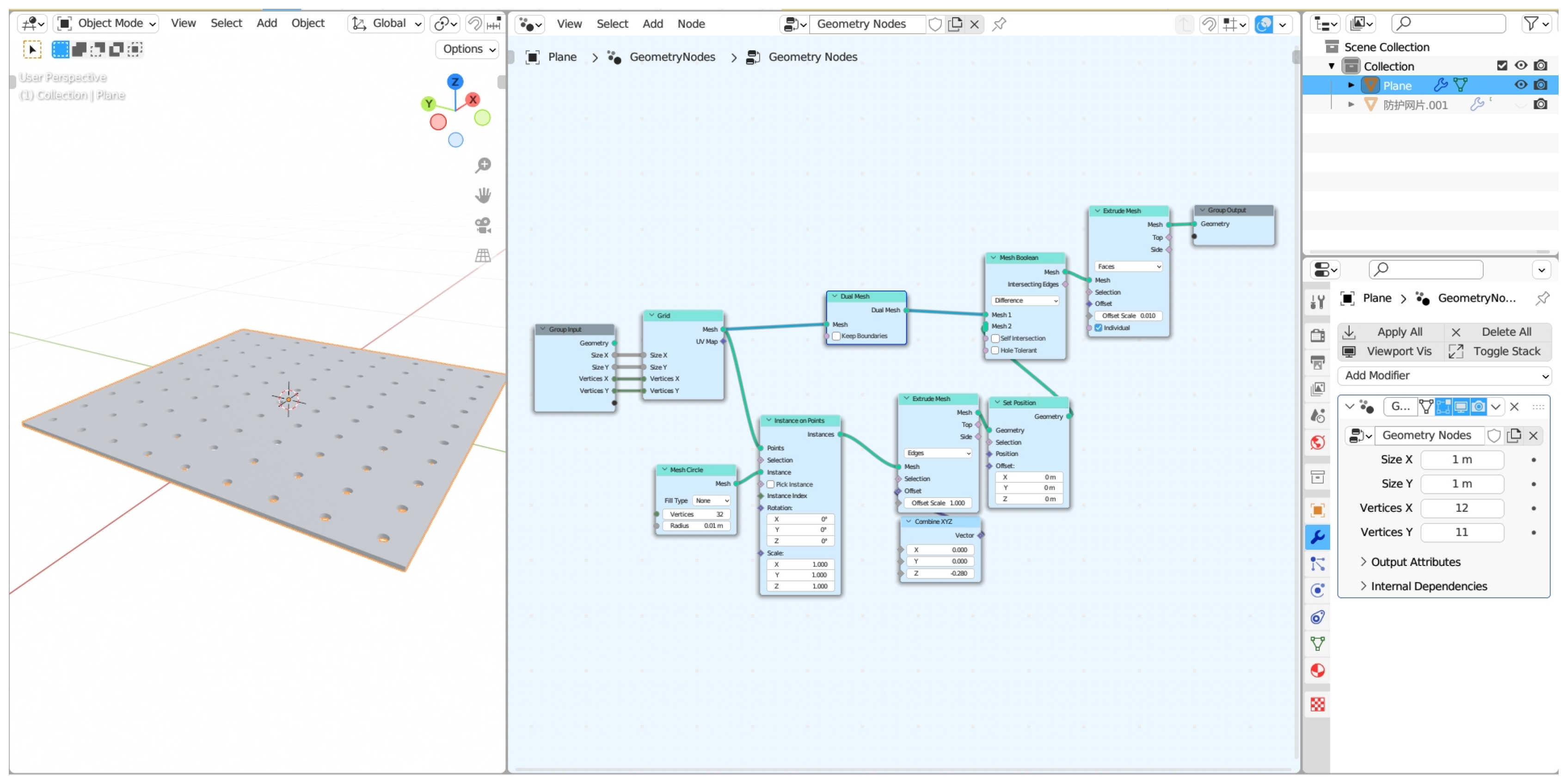
Within Blender, the integrated Geometry Nodes feature serves as an effective tool for parametrically modeling protective net panels. Geometry Nodes (GN) can add existing models within the scene or generate them through curve nodes and mesh nodes, as depicted in
Figure 5. To generate protective mesh panels, the process begins by adding a grid through a mesh node. The four attributes of the grid node are then connected to input nodes to facilitate parameterized changes. The instantiation on the points node is employed to generate circular curves on the grid, followed by an extrusion node to extrude the circular curves along an axis. Finally, a Boolean operation is performed with the grid to obtain the mesh surface, as depicted in
Figure 6. Using the same approach, another surface is generated, and thickness is added through extrusion. The contents are then merged with a combined node to obtain the mesh panel. The overall generation of the protective mesh panel is completed by using mesh nodes to generate the framework, followed by adding materials. The detailed generation process is illustrated in the breakdown in
Figure 7 and the overall depiction in
Figure 8. Additionally, this parametric model allows users to change the number and size of voids in the mesh panels according to their preferences, as seen in
Figure 9.
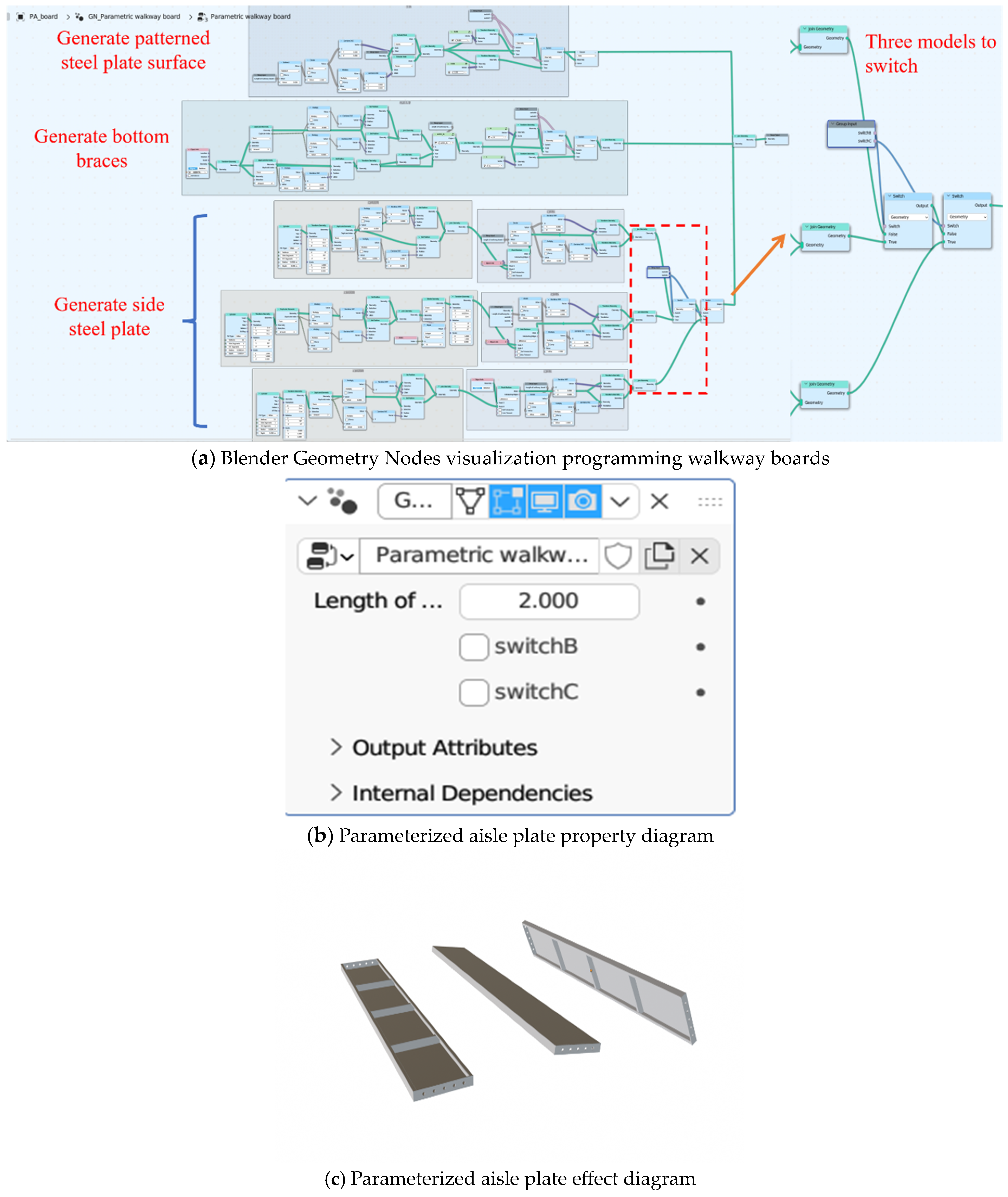
Walkway boards are crucial structural elements in the building machine platform, providing construction workers with a safe and stable surface for walking during construction. However, because the requirements for different projects may vary, there are numerous types of walkway boards, which can pose challenges in design, production, processing, and installation/removal.
To reduce the diversity of walkway board specifications, parametric design is employed using the Blender platform. Initially, all specifications and types of walkway boards are gathered, and data are organized and analyzed. According to the data presented in
Table 3, there are eight models of Type A walkway boards, eight models of Type B walkway boards, and six models of Type C walkway boards. The wide variety of walkway board types results in complexity in design, production, and construction. To address this issue, comprehensive parametric modeling of walkway boards is carried out. By analyzing the types and dimensions of walkway boards, they are fully parametrically modeled. This approach simplifies the process of invoking different board types within the model.
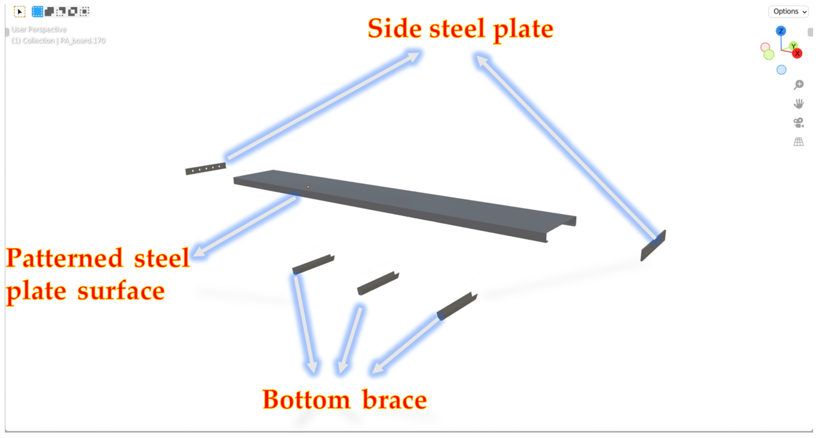
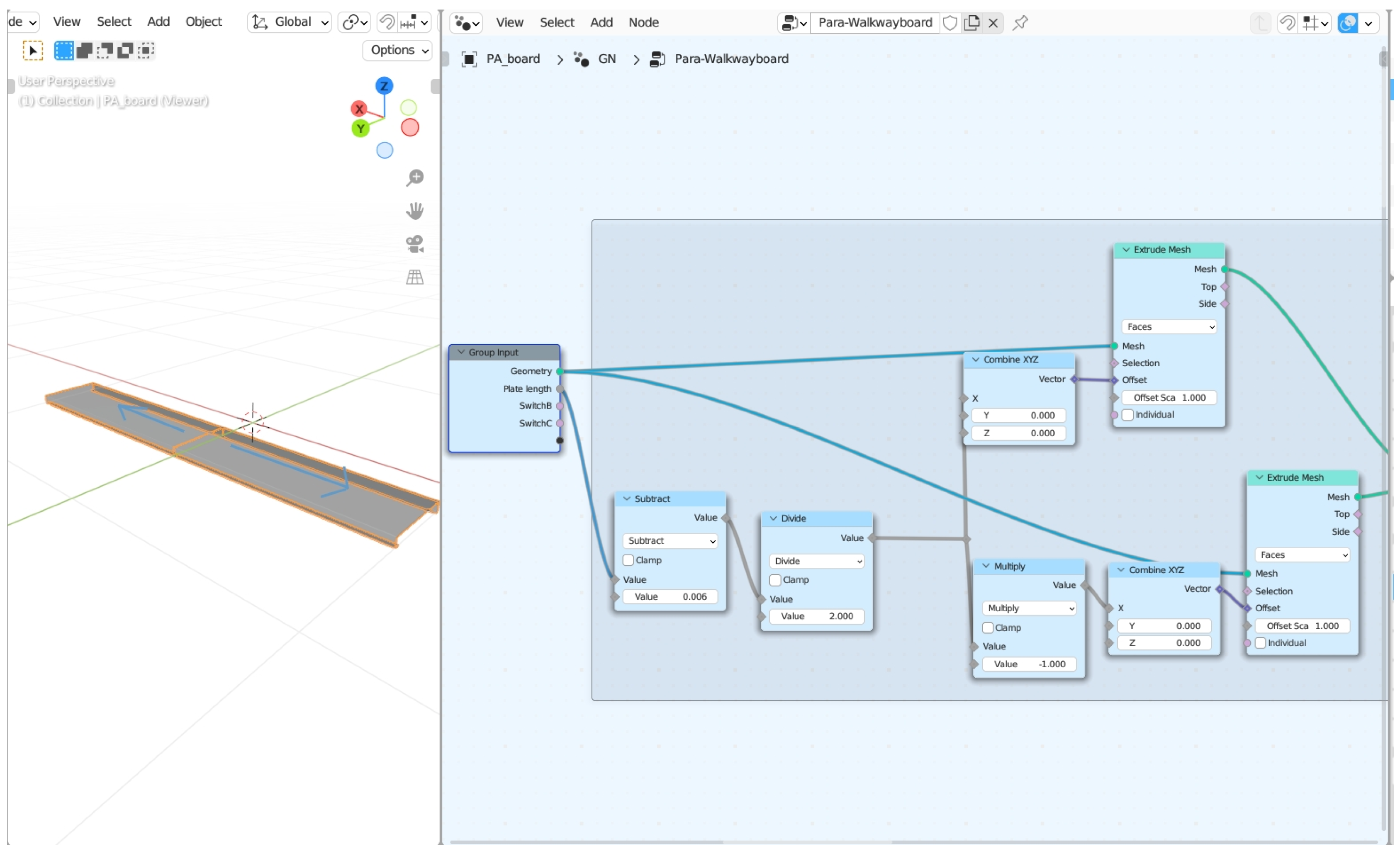
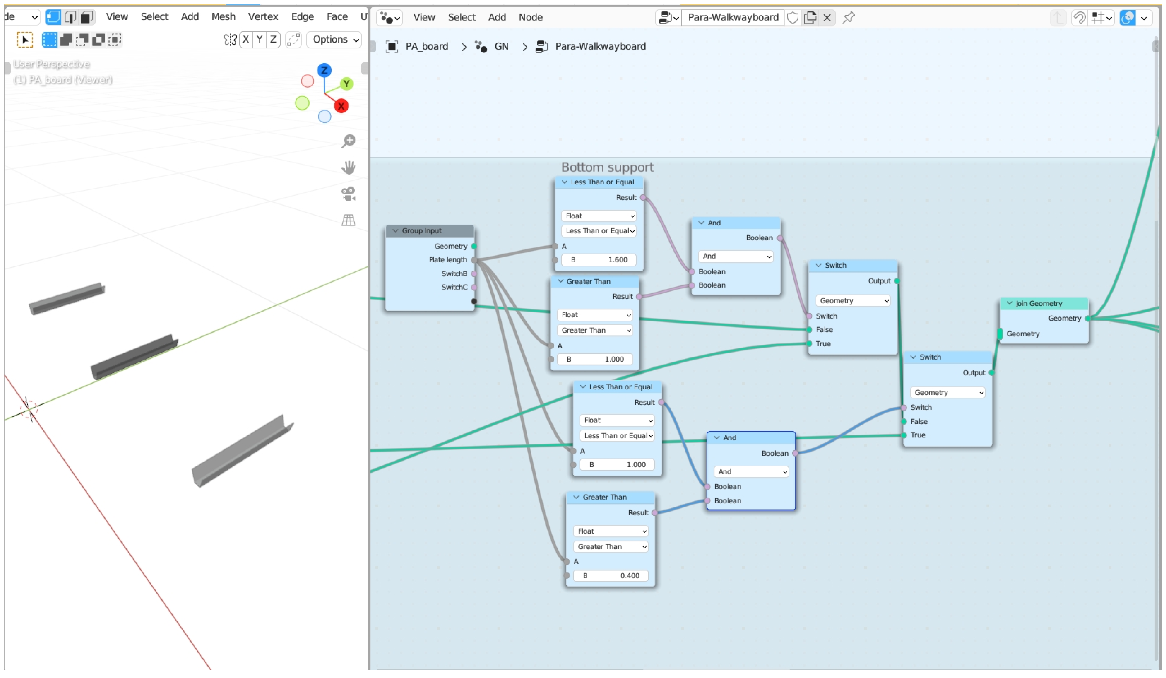
Walkway boards are classified into three types, A, B, and C, based on their width. When performing parametric modeling, the walkway board model is first divided into multiple components, including the walkway board patterned steel plate surface, the walkway board bottom cross brace, and the walkway board side steel plate, as shown in
Figure 10. Leveraging the powerful geometric node functionality of Blender, utilizing the extruded mesh node, the tread plate pattern on the steel plate surface of the walkway board is extruded with equidistant displacement, as shown in
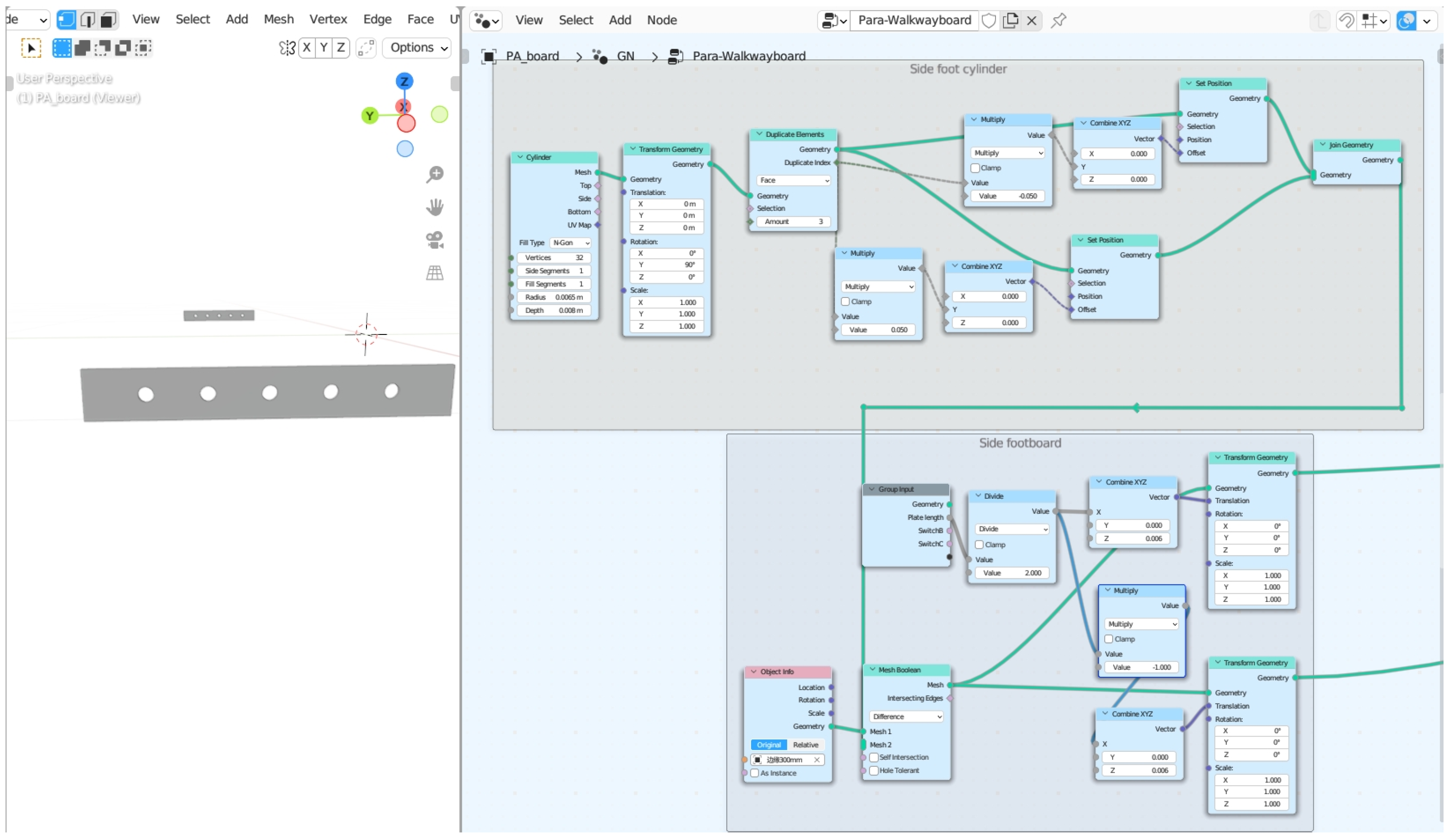
Figure 11, while ensuring synchronized movement with the side steel plate of the walkway board. With three different types of walkway boards, a switch node is employed to achieve simultaneous changes among them, as depicted in
Figure 12. For each type of walkway board, the modeling of the bottom cross brace is parameterized based on its size information, and the number of bottom cross braces is controlled accordingly. The modeling process for the bottom of the walkway board follows a similar approach, emphasizing the use of a switch node and arithmetic nodes to ensure a perfect match among the three types, as shown in
Figure 13. Once the parametric modeling of the walkway board is completed, users have the flexibility to make adjustments based on their requirements using the modifier properties panel, as demonstrated in
Figure 14.
3.1.2. Parametric Generation of the Hanger System
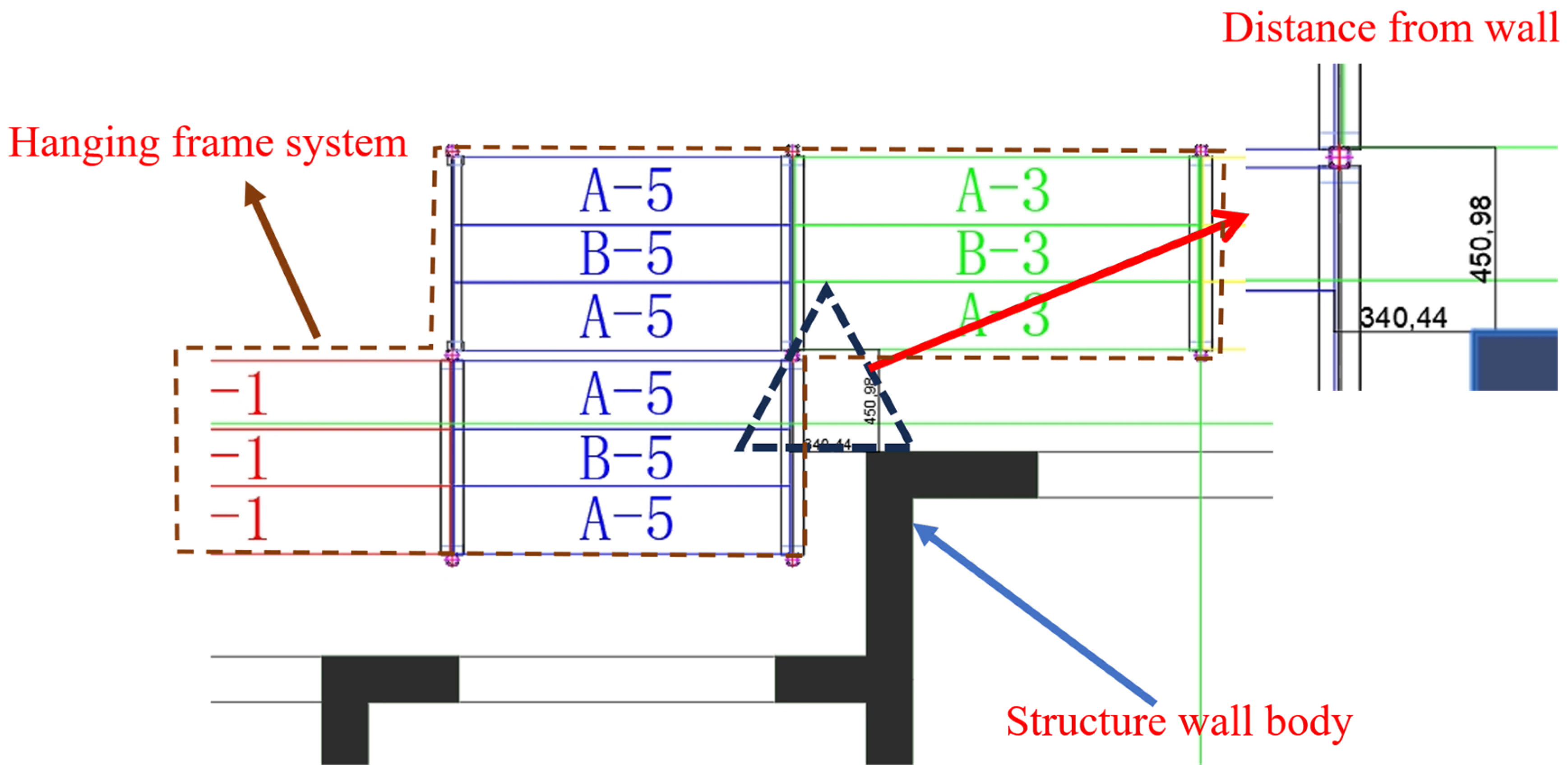
After completing the parameterized modeling of individual components, we employ specific rules for the assembly and integration of the construction crane hanging system, achieving an overall parametric generation of the hanging system. Initially, we import the outer contour lines of the building structure’s plan and fine-tune these outlines for optimization, given that the construction crane hanging system typically resides 300–450 mm from the exterior contour of the building structure, as depicted in
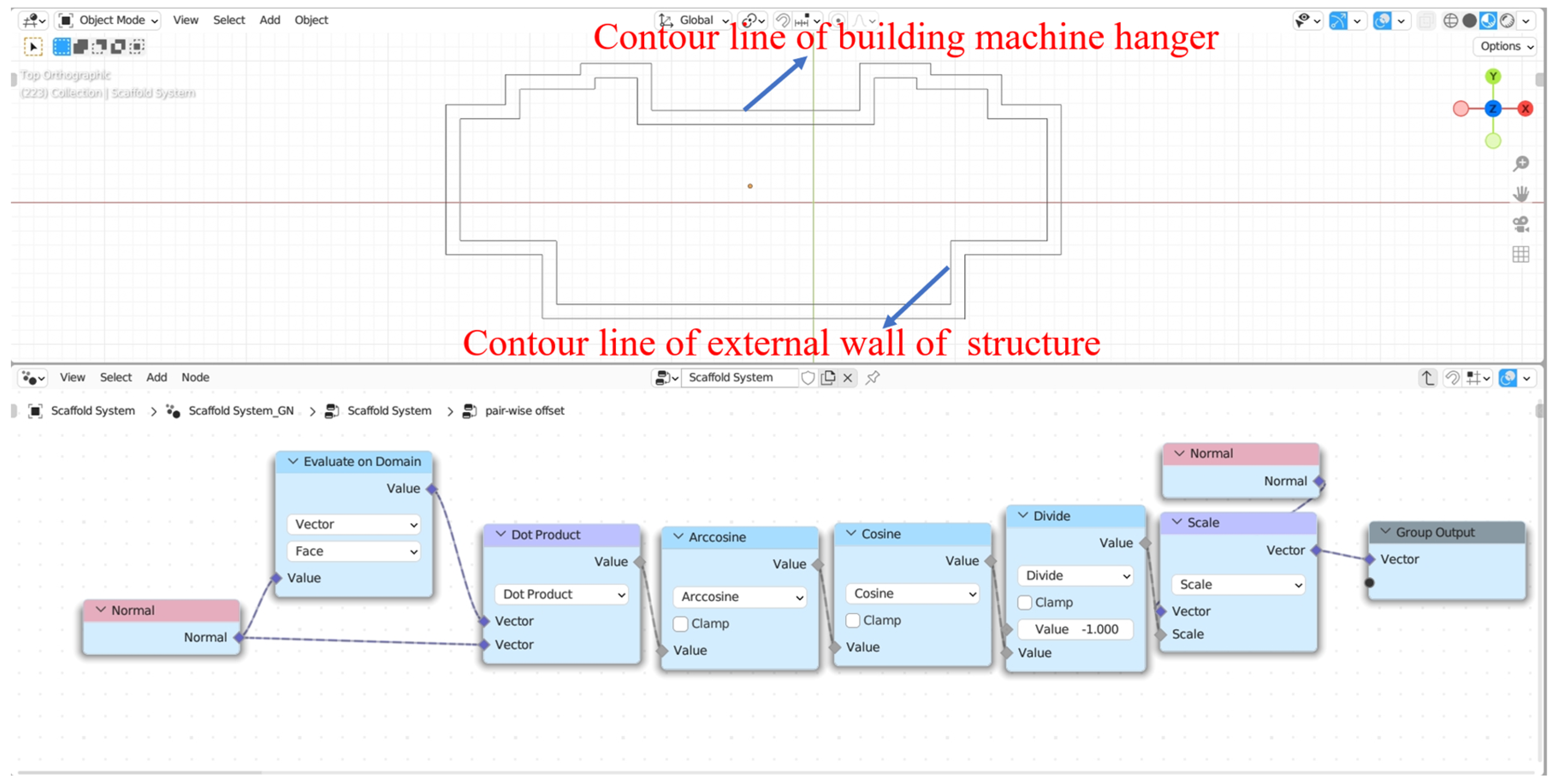
Figure 15. Subsequently, following prescribed guidelines and utilizing the visual programming tool GN, we calculate the equidistant displacement of the building structure’s plan outline, thereby generating the outline for the construction crane hanging system, as illustrated in
Figure 16.
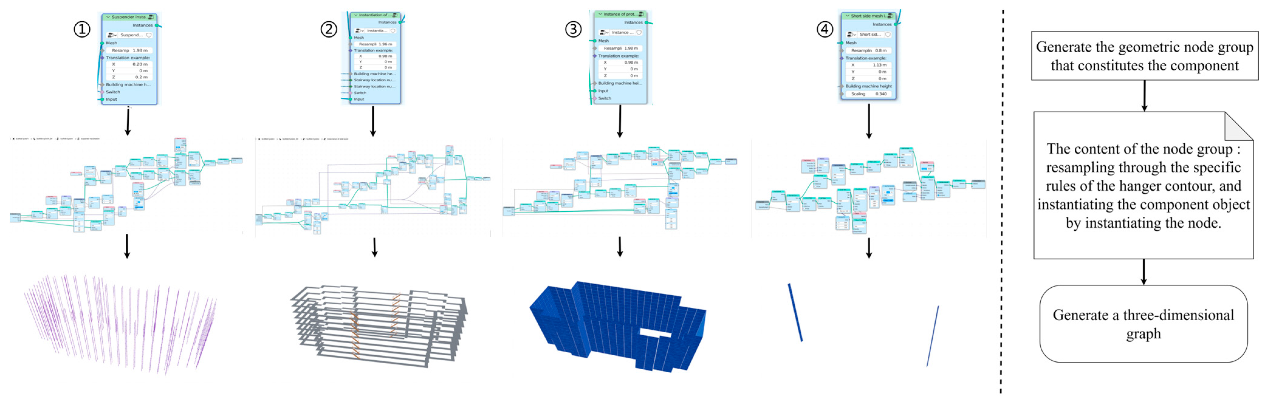
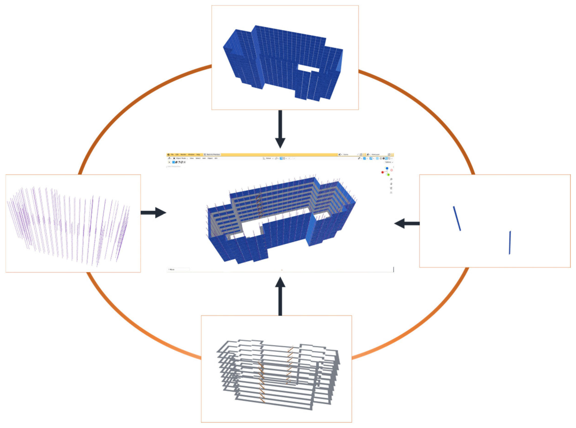
Following this, the components of the scaffolding system are combined. The scaffolding system of the tower crane generally consists of 6–8 layers, with a fixed spacing between each layer. Walkway boards, safety nets, suspension bars, cross braces, stairs, and others are instantiated vertically using GN tools, as shown in
Figure 17. Then, using the visual programming tool GN, these vertically instantiated components are further instantiated to form the scaffolding system, as shown in
Figure 18, completing the parametric generation of the tower crane’s scaffolding system, as shown in
Figure 19.
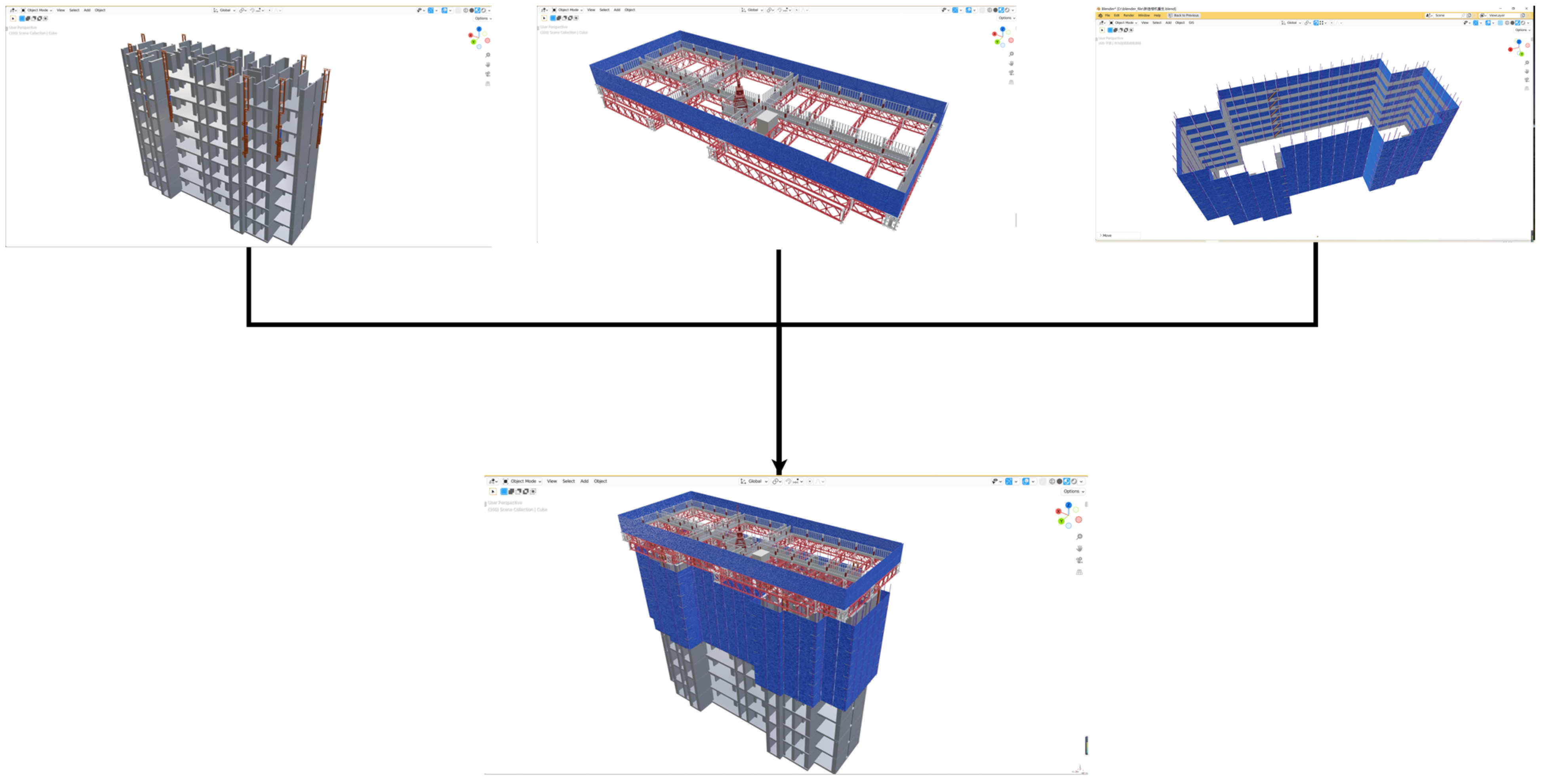
After completing the design of the referable components, the modeling of the other parts of the building machine and the building is continued. Firstly, the CAD building structure drawing is imported into Blender for processing, and the GN tool is used to parametrically generate the main body of the building so that the number of floors can be changed. Secondly, after generating the building model, the arrangement of the support columns is carried out, and the number and position of the support columns are determined by considering the force conditions. Finally, the upper steel platform is arranged. As the main platform system in the building machine, the steel platform is composed of beret frames and connectors and is used as the attachment point of the hanger system, the placement point of the fabric machine and the control room, etc. In different projects, its arrangement needs to be recalculated and designed according to the shape of the building body and the different pressure-bearing capacities. Therefore, the steel platform does not apply to the parameterized automatic one-key generation and needs to be manually arranged according to the stress situation and the arrangement of the pivot point. The final arrangement with the building body is shown in
Figure 20.
3.2. Virtual Simulation
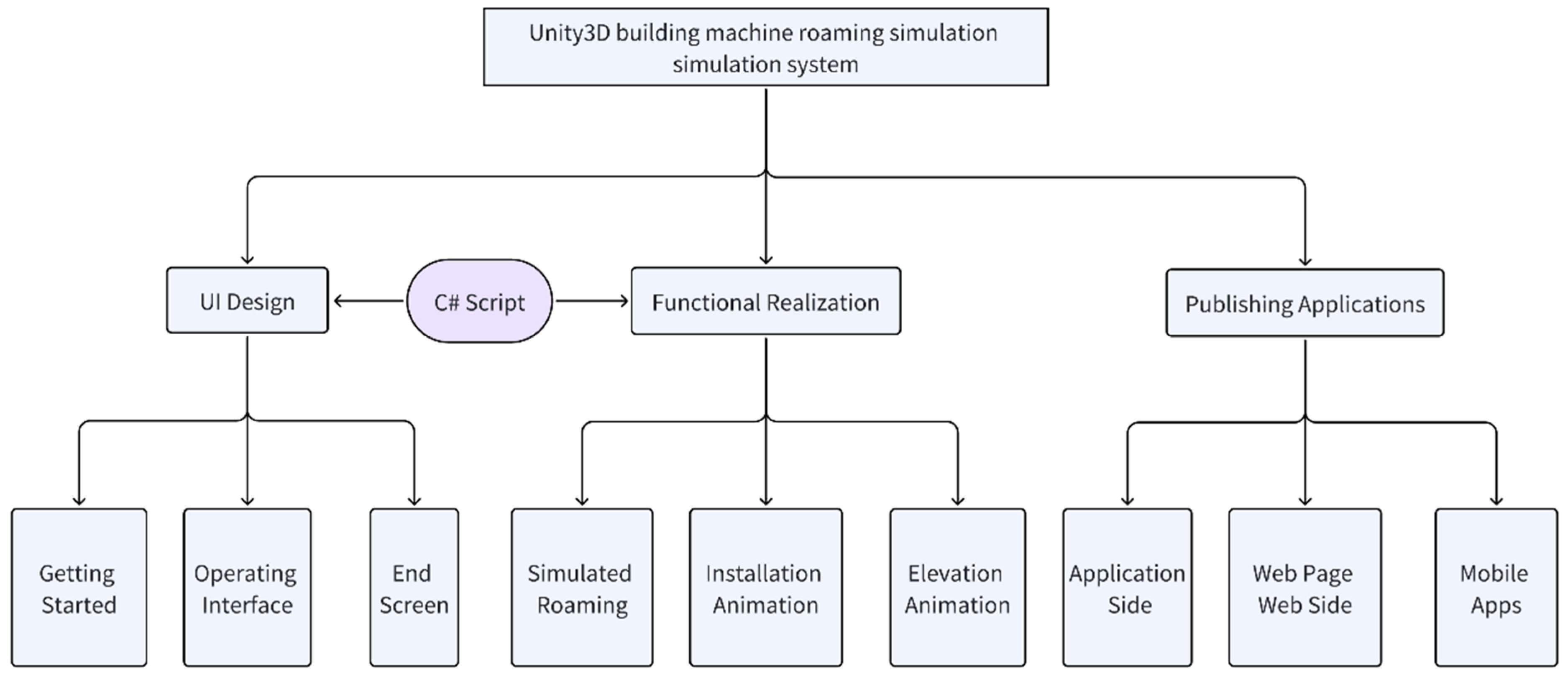
The three-dimensional model of the building machine has the characteristics of intuition, good visualization, and so on. In the construction site, there are often a variety of problems; construction personnel often struggle, based on the design of two-dimensional drawings, to cope with some thorny issues, but two-dimensional drawings cannot be visualized, hence the need for in-depth understanding of the construction personnel, which is not conducive to the work on the site, affecting the construction progress. In recent years, virtual reality technology in the construction industry has continued to develop, including the use of three-dimensional model interactive visualization and other ways to combine the construction site, which are more conducive to the construction staff’s ability to control the site and more efficient construction operations. In this paper, the three-dimensional model of the building machine and Unity3D fusion, as well as the C# development language, are used to establish the building machine roaming simulation system. As shown in
Figure 21, the construction personnel on the site are able, through the client, at any time, to view the three-dimensional model of the building machine, installation and demolition dynamic display, operation and maintenance simulation, etc., to facilitate the construction personnel by comparing with the actual situation on the site. With this system, the construction staff can be guided to help assist in the operation of the construction work.
3.2.1. Model Data Import
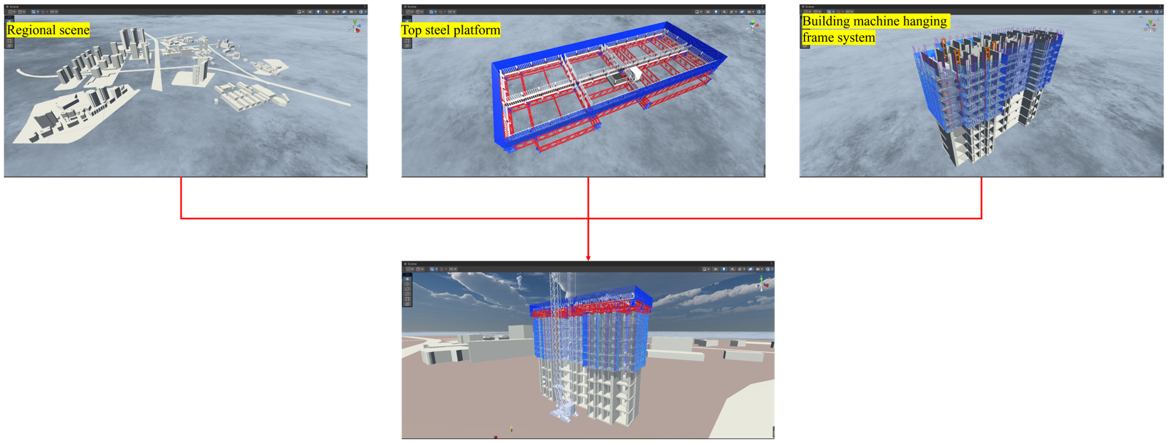
Blender 3D modeling software has a powerful import and export function, which can export GLB, FBX, STL, and other formats. It can realize the interface with Unity platform. There are geometric node functions, different materials, animation effects, etc., in the 3D model of the building machine, while FBX supports 3D models, scene levels, material lighting, animation, bones, masks, and mixed shapes. It is the gold standard for supporting all kinds of data in its format. Comprehensively consider exporting the FBX format through the use of Blender for best results. Further import the building machine 3D model with geometry nodes, materials, and other building machine 3D model FBX files into the Unity project, as shown in
Figure 22.
3.2.2. Interaction Design Function Realization
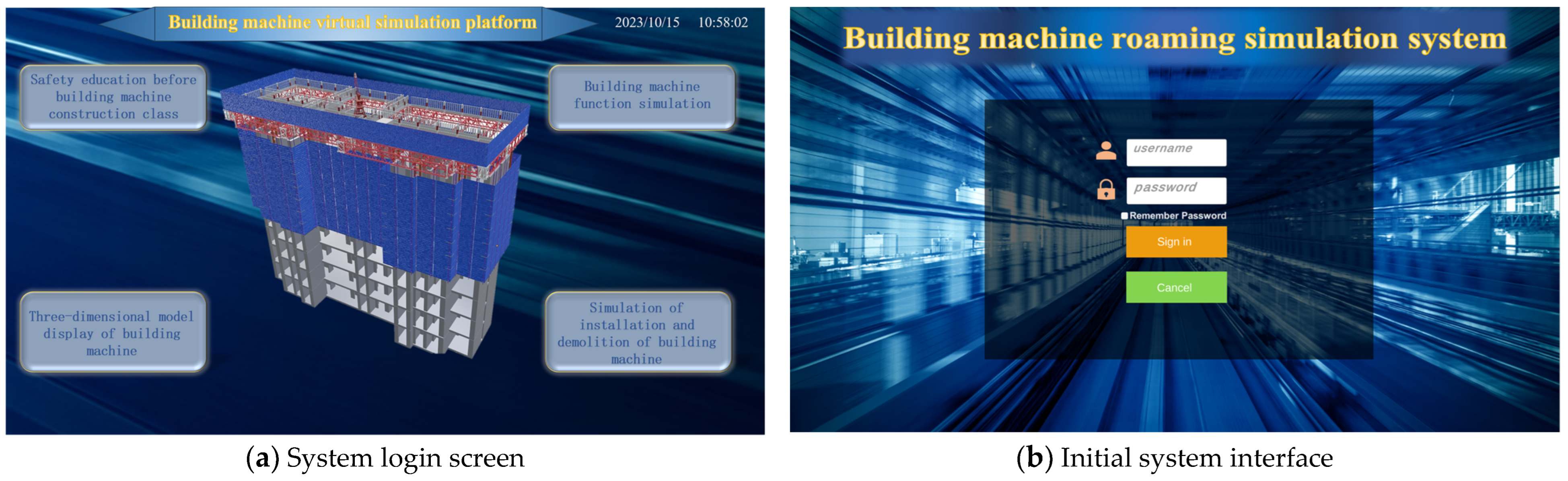
Through the imported models, different scenes are created, including the start scene and the program running scene. The interface start scene is designed through the UI in Unity3D, and different buttons are created according to the system requirements to switch to the relevant scene, as shown in
Figure 23. The corresponding program is written so that it can have the functions of pre-shift education, 3D display, operation simulation, and simulation of the installation and dismantling of the building machine. In the running scene of the program, you can see the overall three-dimensional model of the building machine and access the information and other operations of each system of the building machine in the virtual scene by pressing the buttons. By writing C# code, we can enable the roaming action, and with the action tag brought by Blender, we can simulate the construction animation.
3.2.3. Construction Guidance and Demonstration Publicity
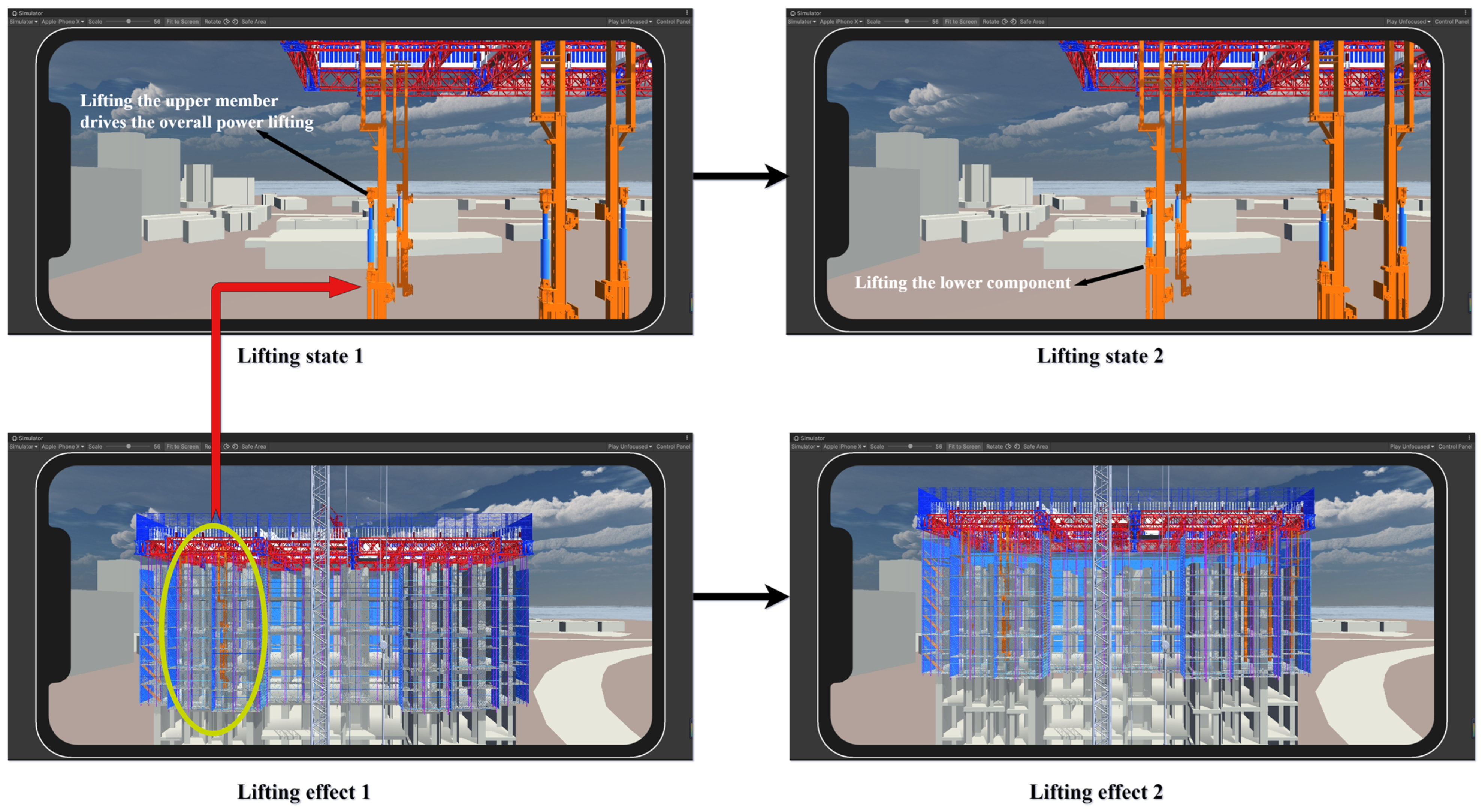
We can use the Unity platform to package and send to a web page, web terminal, or cell phone terminal this information, including the building machine 3D model display, simulation roaming, dynamic display including the installation and dismantling animation, etc., to achieve the above functions. In the construction site, construction personnel can use hand-held equipment for operation guidance work; in the installation and dismantling, the simulation system can be used to understand the process, making it easier to carry out on-site operations. When there are problems with the placement of components on the site, they can view the virtual simulation of the relevant part of the model in a timely manner in order to better cope with some of the problems on the construction site, as shown in
Figure 24. In terms of product promotion, a good product must have a good way to publicize. Through the use of mobile client for building machine virtual display, we can allow the customer, in the fastest and most intuitive way, to understand the building machine’s method of construction, working mode, operation, etc., helping to promote the product and increase market competitiveness.
4. Results and Discussion
The method proposed in this paper has been applied to a built residential project of a construction company in Wuhan, China, which has a total building area of 326,900 m², and the construction of the project requires a total of four residential building machines. The building machines were divided into two groups to validate the applicability of the proposed method. The first group of two building machines utilized traditional design methods, employing 2D architectural structure drawings for two-dimensional plane design. The second group of two building machines employed the parametric 3D design method proposed in this study. After both groups completed their respective designs, the results are summarized in
Table 3. In the first group, designers used traditional design approaches to design and layout the building machines. Due to the lack of intuitiveness in the 2D design plane, it was challenging to directly observe potential issues such as collisions or formwork interference between building machine components. This led to multiple modifications during the design process. The second group of designers used this method to import the outer contour lines of the building structure into Blender and then utilized the well-constructed geometric node group of the building machine hanger system to input the contour lines into the geometric node group, which can quickly generate the 3D model drawing of the building machine hanger system. The steel platform system and support system are manually arranged because they need to be analyzed via force calculation according to the structural plan of the building. Finally, the generated 3D model is imported to the Unity platform for virtual simulation system development. By utilizing the parametric method proposed in this paper and conducting virtual interactions within a virtual environment, the design and layout of the building machine were completed rapidly. This approach provided a clear and intuitive visualization of potential issues such as collisions or formwork interference between building machine components. Compared with the traditional design method, as shown in
Table 4, the results show that the parametric design scheme of the building machine quickly generates a 3D model and provides a virtual simulation platform for the safety and education of construction personnel, as well as construction guidance. It proves that the method is effective.
The emergence of building machines solves the problems of low safety, high danger, backward technology, and single function that exist in traditional construction technology. A building machine collects hanger systems, jacking power systems, formwork systems, auxiliary work systems, and other functions, which are widely used in the field of high-rise and ultra-high-rise building construction. It has very high application value in China. Foreign construction methods are still mainly based on the climbing system, like the building machine; the applicability of this kind of holistic safety platform is less than the building machine, but the current design of the building machine is still stuck in the traditional two-dimensional design concept, resulting in slower design efficiency, program modification complexity, and poor intuition. Based on the above problems, the method proposed in this paper is a better solution to these problems, which has a guiding significance for construction.
The purpose of this research is to optimize the design and construction of the building machine through parametric methods and virtual construction simulation. The results show that, through this method, the use of Blender 3D modeling software and Unity simulation software, 3D parametric modeling of the building machine, as well as simulation of the installation and dismantling, the design time can be effectively shortened, and it is conducive to the changes and modifications of the later program.
Through parametric design, reusable building components or templates can be created in Blender, reducing the time and workload for designers to design from scratch in each project. This improves design efficiency and generates design solutions for high-rise building construction platforms faster. Through virtual simulation, a virtual model of a high-rise building construction platform can be created in Unity and the construction process can be simulated. This can help the construction team to better plan the construction sequence, optimize the use of resources, reduce conflicts and problems in the construction process, and improve the construction efficiency. Through virtual simulation, possible design flaws, construction difficulties, or conflicts can be found in the simulation environment and measures can be taken in advance to solve them. This reduces errors and delays in the actual construction and lowers project risks and costs. Virtual models created with Blender and Unity provide highly realistic visualizations that help the project team and relevant stakeholders better understand and communicate the design intent. This helps to minimize misunderstandings and conflicts and facilitates collaboration and coordination among all parties. Moreover, with today’s emphasis on sustainable development, integrating the concept of sustainable construction into the minds of future designers will contribute to advancing technological efficiency in the construction industry regarding sustainable building practices.
The parameterization method is currently applicable to high-rise buildings with the hanger system attached to the outer wall and cannot be used for residential building machines or light building machines. Due to the existence of the inner hanger system in aerial building machines and the fact that the inner hanger system is not the same for each layer of the hanger, which results in the inability to use the parameterization for generation, it is necessary to further design a new parameterization method and plug-ins to solve this problem. It is also possible to combine the parametric method proposed in this paper with non-parametric methods manually constructed by individuals to complete the three-dimensional design scheme. Alternatively, the parametric method proposed in this paper can be modified to accommodate the presence of an internal hanging frame system in aerial building machines.
5. Conclusions
This paper explores the parametric design and construction technology of building machines according to their characteristics, relying on Blender 3D open-source software and combining it with the Unity3D virtual visualization platform, and puts forward a parametric modeling method of building machines and the corresponding technical route. Through the creation of individual components, joint parameterization of components, and visualization simulation of the building machine, an efficient and convenient new design method is proposed. The feasibility and engineering applicability of the parametric building machine intelligent modeling technology are verified by taking a built residential project of a construction company in Wuhan, China, as an example; the applicability and completeness of the BIM model are verified by the demonstration of the results of the Unity 3D visualization and digital simulation. The results show that the parametric modeling technology of the building machine and the visualization simulation can quickly generate the model, as well as the arrangement method, and simulate the running state of the building machine, which has a certain guiding effect on the application of BIM technology in the construction equipment of the building machine. This study innovatively combines parametric design with virtual simulation, applying it to the design of a crucial component in high-rise construction equipment—the building machine. By validating the advantages of 3D parametric design, this research provides empirical evidence for the replacement of traditional 2D plane design with 3D parametric design in the field of architecture. Simultaneously, leveraging virtual simulation technology to import models into virtual environments for interactive simulations establishes favorable conditions for further research on the integration of building machines with virtual reality (VR), augmented reality (AR), mixed reality (MR), and other related areas.
In the future, on this basis, we can continue to dig deeper into the application of engineering projects in all stages of their whole life cycle, combined with artificial intelligence and big data, to form an integrated platform for the whole life cycle of building machine construction with planning, design, construction, operation, and management. Using parametric modeling with virtual construction processes for architecture makes the building machine function more intuitively and automatically. It has far-reaching significance for future construction methods.
Author Contributions
Conceptualization, Y.Z. and Z.S.; Methodology, Z.S.; Software, Z.S., H.P., W.T. and D.D.; Validation, Y.Z. and D.D.; Formal analysis, Y.Z. and Z.S.; Investigation, Z.S.; Resources, H.P. and W.T.; Data curation, Z.S.; Writing—original draft, Y.Z. and Z.S.; Writing—review and editing, Y.Z. and Z.S.; Visualization, Z.S.; Supervision, Z.S., H.P., W.T. and D.D.; Project administration, Y.Z. All authors have read and agreed to the published version of the manuscript.
Funding
This research received no external funding.
Data Availability Statement
Data are available from the corresponding author and can be shared upon reasonable request. The data are not publicly available due to confidentiality.
Conflicts of Interest
Authors Han Pan and Wenlei Tu were employed by the China Construction Third Bureau Intelligent Construction Robot Co., Ltd. The remaining authors declare that the research was conducted in the absence of any commercial or financial relationships that could be construed as a potential conflict of interest.
References
- Kim, K.; Teizer, J. Automatic Design and Planning of Scaffolding Systems Using Building Information Modeling. Adv. Eng. Inform. 2014, 28, 66–80. [Google Scholar] [CrossRef]
- Kim, K.; Cho, Y.K.; Kim, K. BIM-Based Decision-Making Framework for Scaffolding Planning. J. Manag. Eng. 2018, 34, 04018046. [Google Scholar] [CrossRef]
- Yu, Z. The road to development of scaffolding and formwork technology. Chin. Buil. Met. Stru. 2008, 38–40. [Google Scholar]
- Zhang, L.; Chen, X.; Lin, B. New Development Evelopment of Formwork and Scaffold Engineering Construction Technique. Archit. Technol. 2018, 49, 590–592. [Google Scholar]
- Kannan, M.R.; Santhi, M.H. Constructability Assessment of Climbing Formwork Systems Using Building Information Modeling. Procedia Eng. 2013, 64, 1129–1138. [Google Scholar] [CrossRef]
- Chen, Q. Application of Climbing Shuttering Technology in Highrise Construction. Hous. Sci. 2012, 32, 48–50. [Google Scholar]
- Xu, H. On the construction technology of sliding mode method and climbing mode method for super high-rise buildings. Hous. Real. Est. 2017. [Google Scholar]
- Li, R.; Lang, Z.; Chang, Z. Construction Technology of Auto-climbing Fromwork in Kongzhong Huaxi Village Project. Constr. Technol. 2011, 40, 238–240. [Google Scholar]
- Matskina, M.M.; Petrochenko, M.V.; Radaev, A.E. Stochastic Model of the Construction Process Implemented with Application of Sliding. Mag. Civil. Eng. 2021. Available online: https://cyberleninka.ru/article/n/stochastic-model-of-the-construction-process-implemented-with-application-of-sliding-formwork (accessed on 11 September 2023).
- Mo, G. Discussion on Key Points of Slip form Construction Technology in High-rise Building Construction. Sci. Technol. Inf. 2022, 20, 72–75. [Google Scholar]
- Xu, M. Application of Attached Lifting Scaffold in Construction Technology of High-rise Building. Jiangxi Build. Mater. 2022, 270–272. [Google Scholar]
- Liao, H.; Du, F.; Liu, W. Design of Modularization Low-position Jacking Formwork in Chongqing IFS. Constr. Technol. 2015, 44, 17–21. [Google Scholar]
- Ge, Q.; Tu, Z. Construction Technology of Low Jacking Formwork for Super Tall Building. Build. Constr. 2013, 35, 502–504. [Google Scholar]
- Zhu, H. Development and practice of lightweight construction operation integration platform for China Construction Third Engineering Bureau. Constr. Arch. 2021, 24–25. [Google Scholar]
- Xu, G.; Deng, H.; Chen, D. Application of Lightweight, Turnable and Efficiency Construction Integrated Platform in Housing Construction. Constr. Technol. 2021, 50, 9–11+18. [Google Scholar]
- Liao, J.; Jiang, J.; Liu, H. Application of Residential Building Making Machine in Construction Process. Constr. Technol. 2022, 51, 45–48. [Google Scholar]
- Liao, H.; Du, F.; Yuan, Y. Design and Construction Technology of lntegrated Construction Platform System of Chongqing IFS. Constr. Technol. 2016, 45, 117–120. [Google Scholar]
- Zeng, J.; Yu, D.; Luo, C. Application of Lightweight Pivot Top Module Integrated Platform in Chengmai Financial Center Building Project. Constr. Technol. 2021, 50, 79–81. [Google Scholar]
- Oltra-Badenes, R.; Guerola-Navarro, V.; Gil-Gómez, J.-A.; Botella-Carrubi, D. Design and Implementation of Teaching–Learning Activities Focused on Improving the Knowledge, the Awareness and the Perception of the Relationship between the SDGs and the Future Profession of University Students. Sustainability 2023, 15, 5324. [Google Scholar] [CrossRef]
- Xu, G.; Lei, Q.; Wu, Y. Application of BIM Technology in the Research and Development Process of Residential Building Machine. Constr. Technol. 2021, 50, 82–84. [Google Scholar]
- Li, J.; Yang, X.; Wang, S. Design of Lightweight lntegrated Platform in Wuhan Yangtze River Center. Constr. Technol. 2022, 51, 25–28+116. [Google Scholar]
- Byun, Y.; Sohn, B.-S. ABGS: A System for the Automatic Generation of Building Information Models from Two-Dimensional CAD Drawings. Sustainability 2020, 12, 6713. [Google Scholar] [CrossRef]
- Globa, A.A.; Ulchitskiy, O.A.; Bulatova, E.K. The Effectiveness of Parametric Modelling and Design Ideation in Architectural Engineering. Sci. Vis. 2018, 10, 99–109. [Google Scholar] [CrossRef]
- Díaz, G.; Herrera, R.F.; Muñoz-La Rivera, F.C.; Atencio, E.; Díaz, G.; Herrera, R.F.; Muñoz-La Rivera, F.C.; Atencio, E. Applications of Generative Design in Structural Engineering. Rev. Ing. Constr. 2021, 36, 29–47. [Google Scholar] [CrossRef]
- Wortmann, T.; Tunçer, B. Differentiating Parametric Design: Digital Workflows in Contemporary Architecture and Construction. Des. Stud. 2017, 52, 173–197. [Google Scholar] [CrossRef]
- Bryde, D.; Broquetas, M.; Volm, J.M. The Project Benefits of Building Information Modelling (BIM). Int. J. Proj. Manag. 2013, 31, 971–980. [Google Scholar] [CrossRef]
- Yang, L.; Zhang, J.; Sun, Y. Application of parametric technology in the design of super high-rise structures. Build. Struct. 2022, 52, 29–37. [Google Scholar]
- Wang, X. Research on Construction Simulation and Unsynchronized Cylinder Jacking Displacement of Integral Steel Platform Based on Revit Parametric Modeling. Master’s Thesis, Shanghai Jiao Tong University, Shanghai, China, 2018. [Google Scholar]
- Li, Y. Parametric Modeling and Mechanical Property Analysis of Jack-Up Platform. Master’s Thesis, China University of Petroleum (EastChina), Qingdao, China, 2018. [Google Scholar]
- Geng, Y. Study on Methods of Parametric Modeling of Jack-Up Platform Based on Catia. Master’s Thesis, Dalian University of Technology, Dalian, China, 2006. [Google Scholar]
- Dong, D.; Zou, Y.; Pan, H.; Zhou, G.; Feng, Y.; Tang, Y. DFMA-Oriented Modular and Parametric Design and Secondary Splitting of Vertical PC Components. Sci. Rep. 2023, 13, 3457. [Google Scholar] [CrossRef]
- El-Diraby, T.; Krijnen, M. Papagelis, BIM-based collaborative design and sociotechnical analytics of green buildings. Autom. Constr. 2017, 82, 59–74. [Google Scholar] [CrossRef]
- Liu, Y.; Van Nederveen, S.; Hertogh, M. Understanding effects of BIM on collaborative design and construction: An empirical study in China. Int. J. Proj. Manag. 2017, 35, 686–698. [Google Scholar] [CrossRef]
- Ratay, R.T. Temporary Structures in Construction—USA Practices. Struct. Eng. Int. 2004, 14, 292–295. [Google Scholar] [CrossRef]
- Hyun, C.; Jin, C.; Shen, Z.; Kim, H. Automated Optimization of Formwork Design through Spatial Analysis in Building Information Modeling. Autom. Constr. 2018, 95, 193–205. [Google Scholar] [CrossRef]
- Sanni-Anibire, M.O.; Abiodun Salami, B.; Muili, N. A Framework for the Safe Use of Bamboo Scaffolding in the Nigerian Construction Industry. Saf. Sci. 2022, 151, 105725. [Google Scholar] [CrossRef]
- Chi, S.; Hampson, K.; Biggs, H. Using BIM for Smarter and Safer Scaffolding and Formwork Construction: A Preliminary Methodology. Available online: https://eprints.qut.edu.au/51324/ (accessed on 8 October 2023).
- Whitaker, S.M.; Graves, R.J.; James, M.; McCann, P. Safety with Access Scaffolds: Development of a Prototype Decision Aid Based on Accident Analysis. J. Saf. Res. 2003, 34, 249–261. [Google Scholar] [CrossRef]
- Zhou, Z.; Yang, Z. Analysis on Causes of Formwork Scaffold Collapse. Constr. Technol. 2010, 39, 394–395. [Google Scholar]
- Kim, T.; Lim, H.; Lee, U.-K.; Cha, M.; Cho, H.; Kang, K.-I. Advanced Formwork Method Integrated with a Layout Planning Model for Tall Building Construction. Can. J. Civ. Eng. 2012, 39, 1173–1183. [Google Scholar] [CrossRef]
- Chou, M. Formwork and Scaffold Technology for Tall Buildings. Constr. Technol. 2013, 42, 62–65. [Google Scholar]
- Li, S.; Yu, Z.; Meng, Z.; Han, G.; Huang, F.; Zhang, D.; Zhang, Y.; Zhu, W.; Wei, D. Study on Construction Technology of Hydraulic Climbing Formwork for Super High-Rise Building under Aluminum Formwork System. IOP Conf. Ser. Earth Environ. Sci. 2021, 769, 032062. [Google Scholar] [CrossRef]
- Xia, J.; Yao, Y.; Wu, X.; Chen, Y. Calculation and Analysis of Hydraulic Automatic Climbing Formwork Equipment for Super-High Building Construction. J. Int. Assoc. Shell Spat. Struct. 2021, 62, 24–36. [Google Scholar] [CrossRef]
- Radaev, A.; Petrochenko, M.; Matskina, M. Stochastic Model of the Construction Process Implemented with Application of Sliding Formwork. Mag. Civil Eng. 2021, 101, 10111. [Google Scholar] [CrossRef]
- Zhao, C. Construction Technology of High-Rise Building Slipform and Climbing Moldino. Build. Technol. Develop. 2016, 43. [Google Scholar]
- Huang, T. Design and Application of Integral Hydraulic Climbing Steel Platform to High-Rise Building Construction. Build. Constr. 2016, 38, 1254–1256+1268. [Google Scholar]
- Luo, F.; Li, S.; Yu, Z.; Meng, Z.; Gu, Y.; Han, G.; Yang, R.; Liu, H.; Yan, L.; Gao, J.; et al. Research and Analysis of Intelligent Construction Platform Technology for High-Rise Buildings. HSET 2023, 62, 203–210. [Google Scholar] [CrossRef]
- Zhong, X. Modular Design and Application of Jack-Raising Formwork in Super High-Rise Core Tube. Master’s Thesis, Jiangsu University, Jiangsu, China, 2016. [Google Scholar]
- Jin, Z.; Gambatese, J. BIM-Based Timber Formwork Design and Modeling. Pract. Period. Struct. Des. Constr. 2023, 28, 04022057. [Google Scholar] [CrossRef]
- Schmitt, R. Die Schalungstechnik: Systeme, Einsatz und Logistik; Ernst & Sohn: Berlin, Germany, 2001; ISBN 978-3-433-01346-5. [Google Scholar]
Figure 1.
Traditional construction technology of high-rise building main structure.
Figure 1.
Traditional construction technology of high-rise building main structure.
Figure 2.
Construction accident-scaffold collapse case.
Figure 2.
Construction accident-scaffold collapse case.
Figure 3.
Building machine principle and real picture.
Figure 3.
Building machine principle and real picture.
Figure 4.
Flow chart of parameterized design of building machine.
Figure 4.
Flow chart of parameterized design of building machine.
Figure 5.
The curve nodes, mesh nodes, and parameterization process within geometry nodes.
Figure 5.
The curve nodes, mesh nodes, and parameterization process within geometry nodes.
Figure 6.
Parametric generation of mesh faces.
Figure 6.
Parametric generation of mesh faces.
Figure 7.
Detailed drawing of the visual programming of the Blender protection mesh.
Figure 7.
Detailed drawing of the visual programming of the Blender protection mesh.
Figure 8.
General diagram of the visual programming of the Blender protection mesh.
Figure 8.
General diagram of the visual programming of the Blender protection mesh.
Figure 9.
Parametric generation of protective mesh sheets.
Figure 9.
Parametric generation of protective mesh sheets.
Figure 10.
Walkway board disassembly.
Figure 10.
Walkway board disassembly.
Figure 11.
Parametric generation of patterned steel surfaces for walkway panels.
Figure 11.
Parametric generation of patterned steel surfaces for walkway panels.
Figure 12.
Parametric generation of steel plates for walkway slab sides.
Figure 12.
Parametric generation of steel plates for walkway slab sides.
Figure 13.
Parametric generation of cross braces at the bottom of walkway slabs.
Figure 13.
Parametric generation of cross braces at the bottom of walkway slabs.
Figure 14.
Parametric detailing of walkway boards and modification of panels.
Figure 14.
Parametric detailing of walkway boards and modification of panels.
Figure 15.
CAD building and walkway slab distance from the wall.
Figure 15.
CAD building and walkway slab distance from the wall.
Figure 16.
Hanger system contour line generation.
Figure 16.
Hanger system contour line generation.
Figure 17.
Component building blocks generated by geometry node groups.
Figure 17.
Component building blocks generated by geometry node groups.
Figure 18.
Generating geometric nodes for the building machine hanger system.
Figure 18.
Generating geometric nodes for the building machine hanger system.
Figure 19.
Hanger system 3D model general drawing.
Figure 19.
Hanger system 3D model general drawing.
Figure 20.
Combination of building machine and building body.
Figure 20.
Combination of building machine and building body.
Figure 21.
Flowchart of Unity3D building machine simulation flowchart.
Figure 21.
Flowchart of Unity3D building machine simulation flowchart.
Figure 22.
Component model imported into Unity.
Figure 22.
Component model imported into Unity.
Figure 23.
Building machine virtual simulation system interface.
Figure 23.
Building machine virtual simulation system interface.
Figure 24.
Building machine virtual simulation operation process.
Figure 24.
Building machine virtual simulation operation process.
Table 1.
Comparison of construction methods for high-rise buildings.
Table 1.
Comparison of construction methods for high-rise buildings.
| Aspects | Traditional Construction Technology | New Building Machine Technology |
|---|
| Scaffolding Formwork Technology | Climbing Mold
Technology | Sliding Mold Technology |
|---|
| Construction Safety | Manual erection and dismantling of scaffolding is required, which involves the safety risks of working at height and movement of formwork. | Adoption of self-elevating climbing formwork machinery and equipment reduces the need for working at height and formwork movement | Manual operation of slip form machinery and equipment, with safety risks of working at height and formwork movement | The adoption of automation and mechanization technology reduces the need for manual operation and work-at-height. |
| Construction efficiency | Low, time-consuming erection and dismantling of scaffolding; construction speed is limited | Higher, enabling continuous formwork movement and construction | Higher, realizing continuous formwork movement and construction | Higher, allowing continuous construction and rapid construction using automation and digital technology |
| Sustainability | Limited, possible resource consumption and waste generation | Limited, possible resource consumption and waste generation | Limited, possible resource consumption and waste generation | Better, adopting advanced energy-saving and environmental protection technologies to reduce resource consumption and carbon emissions |
| Construction quality | Subject to skill level; quality and accuracy may vary | High, precision control systems and machinery provide high-quality construction and accuracy | High, precision control systems and mechanical devices provide high quality construction and accuracy | High, precision control systems and machinery provide high quality construction and accuracy |
| Operability | Requires training and skill acquisition | Requires training and skill acquisition | Requires training and skill acquisition | Easy to use and quick for the operator to get started. |
Table 2.
The main components of the building machine.
Table 3.
Table of walkway panel types.
Table 3.
Table of walkway panel types.
Walkway Board Type Summary
(Type A Is 300 mm Wide, Type B Is 250 mm Wide, Type C Is 200 mm Wide) (Unit: mm) |
|---|
| Type A walkway board | A × 2000 | A × 1900 | A × 1700 | A × 1600 | A × 1500 | A × 1300 | A × 1200 | A × 800 | A × 700 |
| Type B walkway board | B × 2000 | B × 1900 | B × 1700 | B × 1600 | B × 1500 | B × 1300 | B × 1200 | B × 800 | B × 700 |
| Type C walkway board | C × 2000 | C × 1900 | C × 1700 | C × 1500 | C × 1300 | C × 1200 | C × 800 | | |
Table 4.
Comparison between conventional and parametric design.
Table 4.
Comparison between conventional and parametric design.
| Aspect | Parametric Building Machine Design | Traditional 2D Design |
|---|
| Design time (hours) | Shorter, average 24 h | Longer, average 90 h |
| Labor requirements (persons) | Less, usually 2 persons | More, usually 5 persons |
| Intuitive | Better, using 3D models | Worse, using 2D plans |
| Fault tolerance | Higher, easy to modify and adapt to changes | Lower, more complex to modify |
| Degree of automation | High, automatic generation of components and models | Low, requires a lot of manual drawing and calculation. |
| Construction guidance and simulation | Support for visual construction simulation | Construction guidance based on 2D drawings |
| Disclaimer/Publisher’s Note: The statements, opinions and data contained in all publications are solely those of the individual author(s) and contributor(s) and not of MDPI and/or the editor(s). MDPI and/or the editor(s) disclaim responsibility for any injury to people or property resulting from any ideas, methods, instructions or products referred to in the content. |
© 2023 by the authors. Licensee MDPI, Basel, Switzerland. This article is an open access article distributed under the terms and conditions of the Creative Commons Attribution (CC BY) license (https://creativecommons.org/licenses/by/4.0/).


