1. Introduction
One of the key strategies for addressing the challenge of climate change is to reduce global energy consumption [
1]. In recent years, efforts to achieve zero-energy consumption of residential buildings have focused on insulating existing structures and installing renewable energy sources (RES) on their rooftops [
2,
3,
4]. Other approaches include optimizing building envelopes to facilitate better harvesting of solar energy [
5,
6,
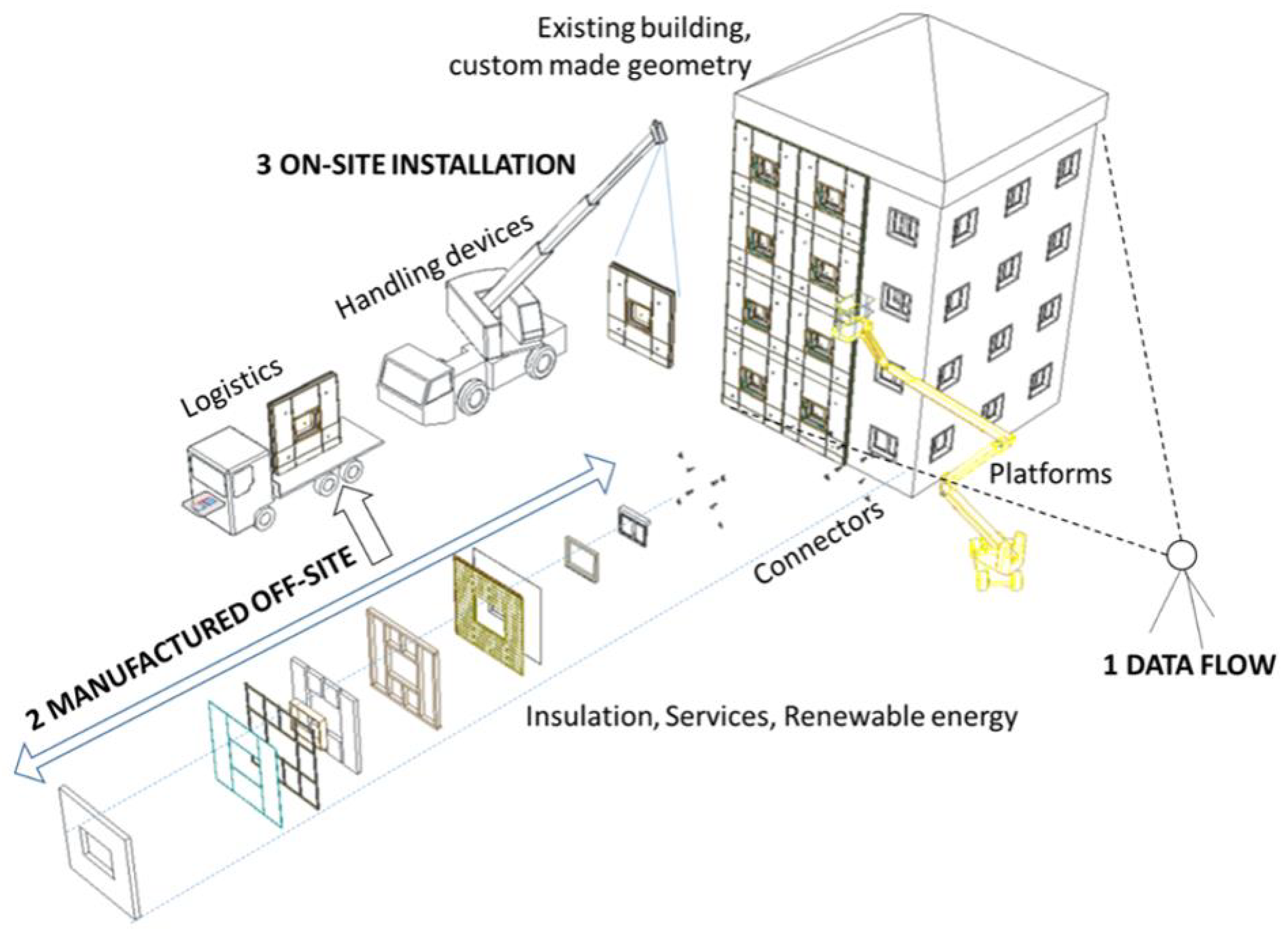
7]. However, manually implementing these measures carries the potential risks of user intrusion, disruptions, and hazardous activities carried out at elevated heights. To circumvent these issues, prefabricated modules are now being manufactured off-site, incorporating insulation, RES, windows, and waterproofing elements [
8]. Previous studies have explored the use of automated, robotic facade renovation with prefabricated modules, which can be categorized into three sub-categories [
9,
10,
11]: information or data flow, off-site manufacturing of the modules, and on-site installation of the modules (see
Figure 1).
The adoption of prefabricated elements in residential building renovation has not yet gained widespread market acceptance due to its lack of competitiveness compared to traditional manual methods. The ENSNARE research project [
12] aims to reduce data acquisition and processing time by 90%, while also reducing the duration of the manufacturing and installation processes. It is crucial to ensure that any reduction in working time does not result in a loss of quality and adheres to regulations and standards [
13]. Errors in the data flow can lead to deviations in the manufactured modules, resulting in water and heat leaks, collisions, or impeded installation processes.
The successful implementation of robotics and automated solutions in residential building renovation largely depends on their economic feasibility [
14,
15,
16,
17]. Furthermore, it is essential to address the issue of managing and preparing such technologies for the market [
18,
19,
20]. Previous research initiatives, including BERTIM [
21] and HEPHAESTUS [
22], have examined this matter. Earlier studies [
23] have identified up to 15 research gaps (RG) in this field.
In the field of residential building renovation, the utilization of prefabricated modules for energy-saving and generation purposes often presents less competitive alternatives compared to manual procedures due to the requirement for more comprehensive and detailed planning. When it comes to prefabricated modules for building renovation, the involved parties, including building owners, promoters, or engineers, must possess a comprehensive understanding of the building’s solar energy generation capabilities, investment costs, and the necessity for insulation in the preliminary stages of the project. To achieve this, it is crucial to have a geo-located three-dimensional (3D) model of the building that can represent the building’s shape, structure, and capability to accommodate prefabricated modules and solar panels. In this context, the layout of prefabricated walls and solar panels assumes a significant role, providing a clear depiction of the number of solar panels that can fit onto the building envelope, the requisite amount of insulation, and the corresponding investment costs. Concerning data acquisition and flow, and to explain the context of this article, it has been determined that the following measures are necessary:
RG1.1: In the initial phases, it is necessary to generate a building model online, meaning without visiting the site. In previous stages of the research, a method to generate building models online was achieved based on facade images and OpenStreetMaps data.
RG1.2: Typically, in building renovation, the initial definition of the prefabricated module layout is a manual process and can take up to 5–20 h for a low-rise building. The aim should be to automatize defining the layout of prefabricated modules with the information of the building modeled online in RG1.1.
RG1.3: On the next stages of the project, once the “client” or building owner approves the budget, the engineering team can afford to visit the building and measure accurately. Using Total Station or even a 3D Laser Scanner can be a time-consuming activity. A faster method was developed based on OpenCV Apriltags [
24].
RG1.4: The measurement accuracy is much higher in RG1.3 than with the technique described in RG1.1. This means that the layout needs to be re-adjusted based on more accurate measurements. Adjusting the layout by manual means is time-consuming. Therefore, we developed a technique to adjust the layout automatically.
This article focuses on describing solutions in order to mitigate research gaps RG1.2 and RG1.4 in the following sections. As said before, RG1.1 and RG1.3 were developed in a previous phase of the research.
2. Addressing RG1.2 by Defining the Layout of the Prefabricated Modules
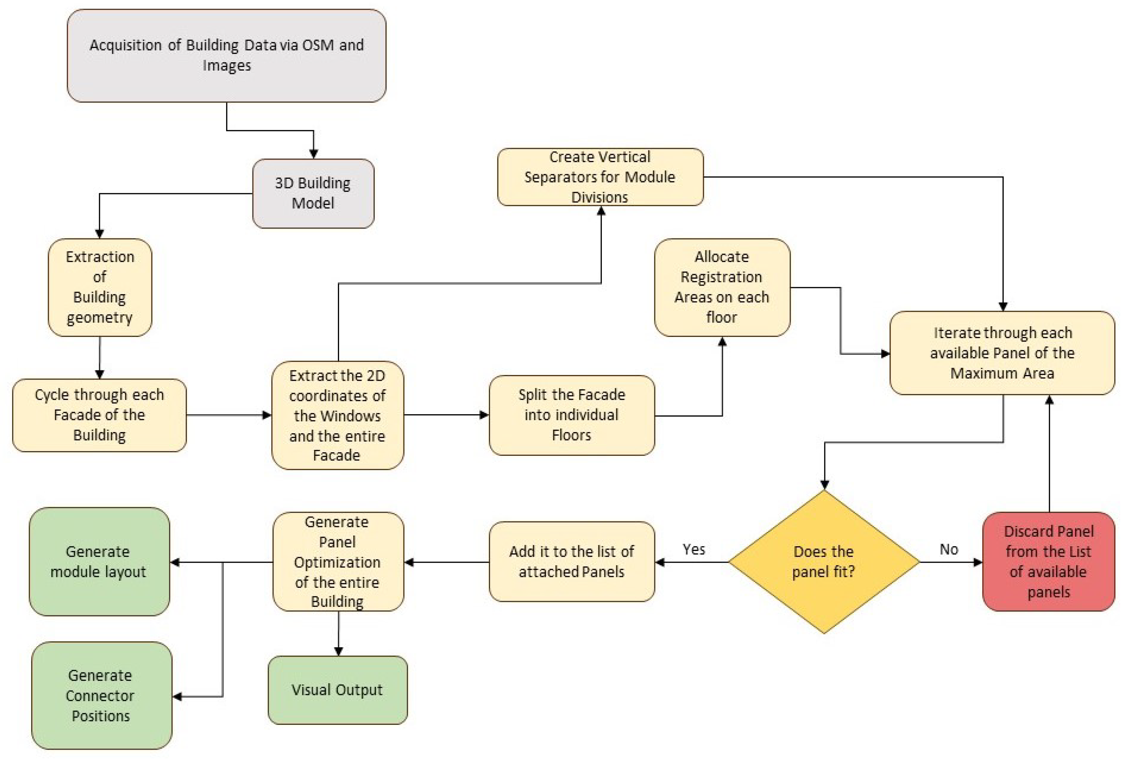
In this section, we explain RG1.2, which is based on the
ENSNARE_MODULE_PLACEMENT, which is a FreeCAD [
25] plugin developed to generate the layout of prefabricated facade modules with solar panels for residential building upgrading. The tool represents a concerted effort to improve the cost-effectiveness and efficiency of residential building renovation within the ENSNARE project. The flow chart in
Figure 2 explains the process of the solution.
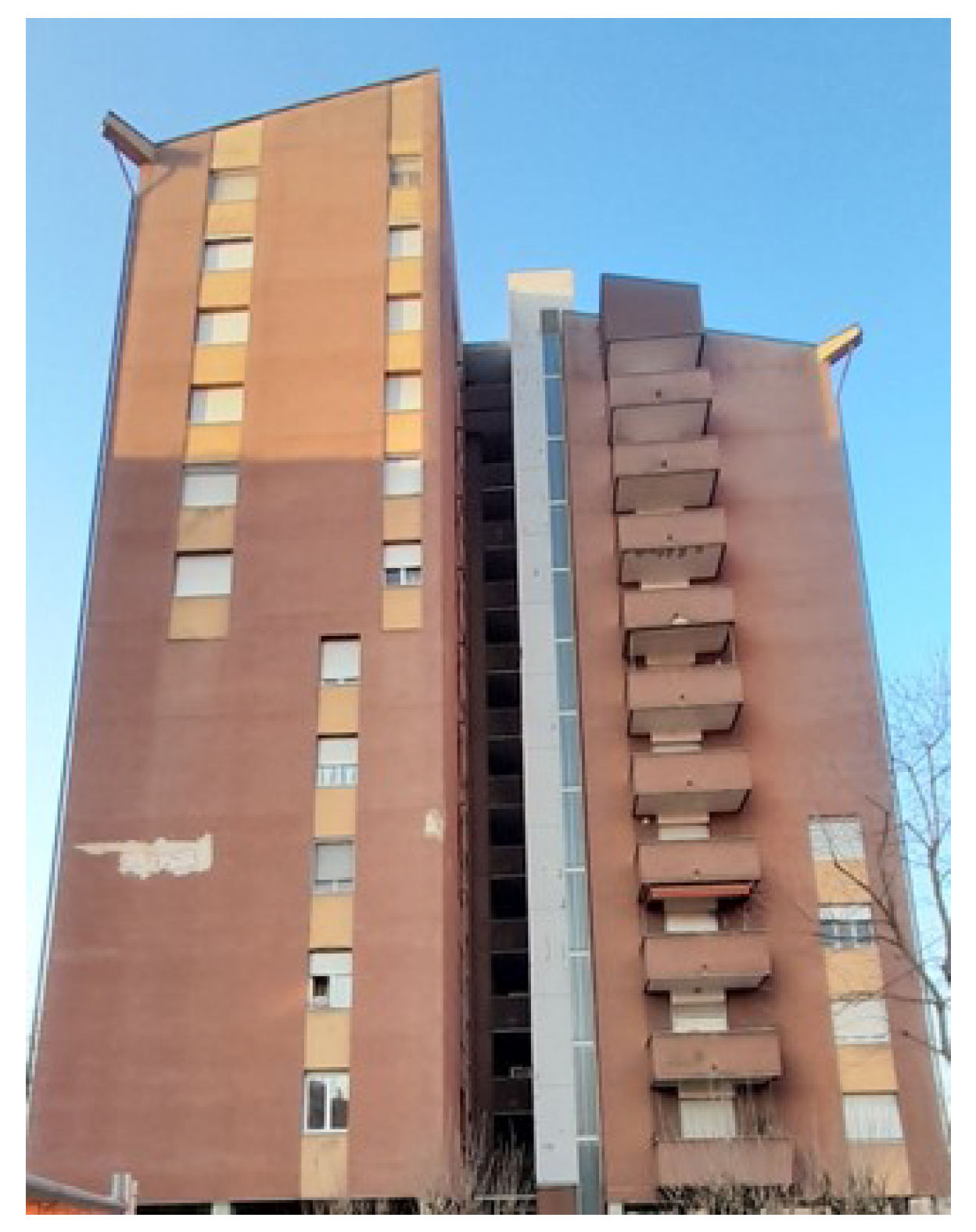
Before applying RG1.2, the ENSNARE project has defined a technique to draft the building model online. In
Figure 3, one of the four pictures of a demo building is shown. This demo-building is part of the ENSNARE research project and it is located in Milan.
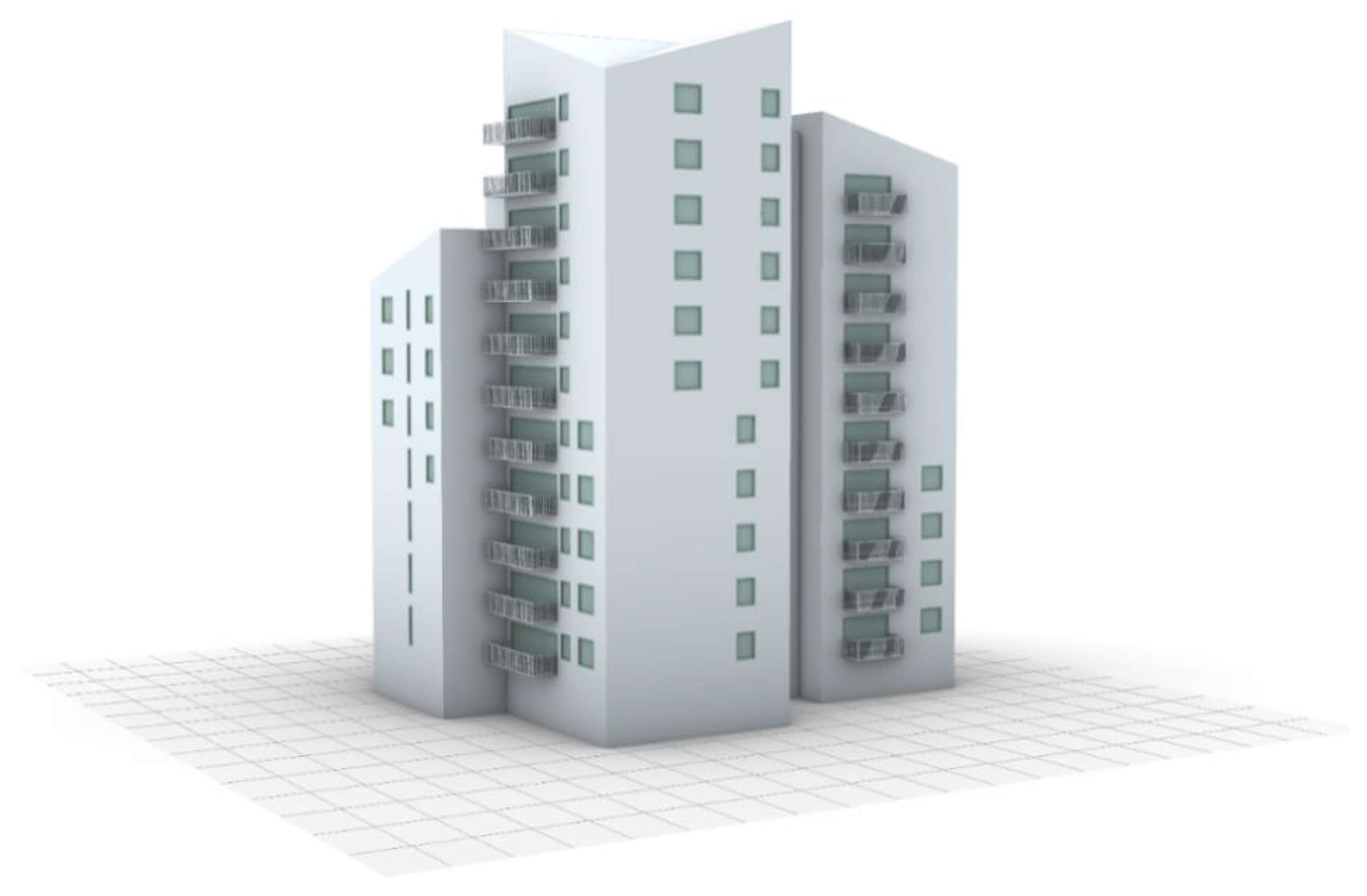
The building model is generated with the images of the building and the OSM information. The building model type that is achieved is shown in
Figure 4.
This building model is the primary input for RG1.2. In the next subsections, each of the steps and the code of RG1.2 are explained.
2.1. Tools Associated with the Plugin
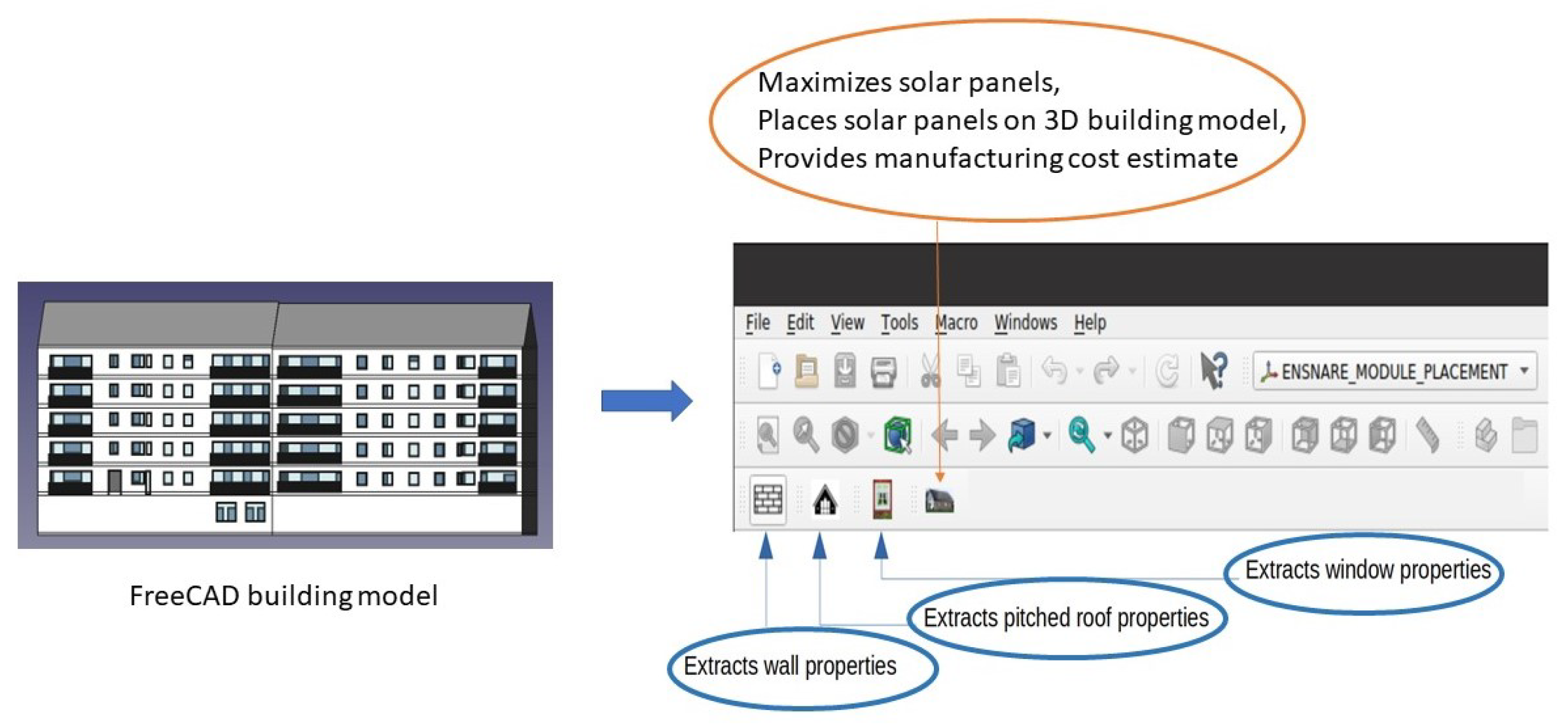
The FreeCAD plugin ENSNARE_MODULE_PLACEMENT comprises several tools that facilitate the generation of the layout of prefabricated solar panel modules with the output of the 3D building model. Each of these tools serves primarily two sets of functions. Namely, a set of tools to extract the relevant information about the 3D building geometries and another set of tools to place solar panels based on the geometric information as explained in
Figure 5.
2.1.1. Extraction of Relevant Information
This research has devised an algorithm for maximizing the number of solar panels of diverse dimensions that can be accommodated on a two-dimensional facade. To implement this algorithm, it is necessary to extract pertinent information related to the building’s facade from the 3D building model generated by the plugin team in ENSNARE.
ENSNARE_MODULE_PLACEMENT is equipped with several tools that enable the extraction of essential information from the online 3D building model, as depicted in
Figure 5. The subsequent subsection provides a comprehensive description of these tools:
1. Tool: exportWallProperties
This tool facilitates the extraction of essential data related to a building facade, such as its height, width, and four corner points. The user can access this tool by selecting the desired facade and clicking on the corresponding icon. Upon execution, the tool generates a JSON file containing the aforementioned information. This tool is implemented in Listing 1 as shown below:
| Listing 1. A Python function which generates a JSON file containing building geometries. |
![Buildings 13 02981 i001]() |
This function uses another function internally: face_dimensions, which shows how exactly the corner vertices and the height and width are determined from the FreeCAD data. This function returns those values to the user. This procedure is described in Listing 2:
| Listing 2. A Python function integral to the previous one. |
![Buildings 13 02981 i002]() |
2. Tool: exportTriangularRoofProperties
This tool serves the purpose of extracting information related to pitched roofs. In some cases, buildings consist of facades with pitched roofs on top. To obtain relevant information such as the height and width of the facade, the topmost point of the roof, and the vertices of the roof, the user must select the appropriate roof and click on the corresponding icon.
The code for generating the required information from a pitched roof is presented in Listing 3:
| Listing 3. A Python tool which extracts relevant geometric information associated with pitched roofs. |
![Buildings 13 02981 i003]() |
3. Tool: exportLBCProperties
This tool is intended to determine the left bottom corner points of a building facade. The need for this tool arises due to the manner in which FreeCAD software version 0.19.3 stores information. In later stages, a 2D projection of the facade is required, and it is necessary to know which portion of the 3D facade corresponds to its left bottom corner. Since it is challenging to select and extract the left bottom corner point from FreeCAD, the sketch file of the left bottom-most window must be chosen, and the button needs to be clicked to obtain the left bottom points of the facade.
4. Tool: exportRBCProperties
This tool has a similar purpose as the previous one, with the difference being that it tracks the right bottom points of the building facade. The need for this tool arises because some building facades have no windows on their left side, only on the right. Since the previous tool uses the corner window positions to determine the corners of the facade for efficient 2D projection, it cannot be used in such cases.
5. Tool: exportWindowProperties
This tool is utilized to collect and store the position, length, and width of all the windows on a given facade. The user selects the sketch files of all the windows present on the corresponding facade and clicks on this tool. The information regarding the position, length, and width of each window is then collectively stored in a JSON file for further use.
2.1.2. Maximizing the Solar Panels
This particular section describes the workbench’s functionality to maximize the total number of possible solar panel modules that can be placed on the facade. Additionally, it also provides a total manufacturing cost estimate for this entire project. This entire functionality is achieved by pressing a single button on the workbench, as described in detail below.
6. Tool: maximize_solar_panel
This tool’s main function is to maximize the number of solar panels that can be fit in a selected facade and also to provide a manufacturing cost estimate. It serves a variety of functions in order to achieve that. Firstly, it projects the entire 3D facade into 2D. For that, it calculates the slope and reference point of the facade by taking into consideration the four corner vertices and the left bottom point of the facade (obtained from previous tools). This procedure is implemented in Listing 4 as shown below:
| Listing 4. A Python function which performs a geometric projection. |
![Buildings 13 02981 i004]() |
![Buildings 13 02981 i005]() |
This tool is designed to extract essential information required for generating the 2D facade and converting it back into 3D after the placement of solar panel modules. It collects the reference point and slope information required for generating the 2D facade, and the 3D orientation of the facade is extracted from its left bottom point. This information is crucial for the placement of the optimized number of solar panel modules in 3D space. Additionally, the tool calculates the 2D positions of all the windows based on the provided data.
Subsequently, the floors within the facade are calculated using a proprietary algorithm as shown in Listing 5. This algorithm considers the list of windows along with their 2D positions and the height of the facade. The algorithm proceeds as follows:
Firstly, it calculates all the top and bottom 2D positions of each window.
Then, it separates all the bottom and top positions into two distinct lists.
Subsequently, the topmost corner positions of a window on a specific floor are computed, and the same applies to the lowermost corner positions.
The corresponding topmost corner points of each floor are compared against the bottom corner point. The floor’s height is then determined as the average of those two values.
| Listing 5. A Python function which returns a list of floors. |
![Buildings 13 02981 i006]() |
![Buildings 13 02981 i007]() |
Then, a text file is generated to provide comprehensive information about the permissible panel and module dimensions, window list within a facade, floors in the facade, as well as the height and width of the facade in 2D, all of which are generated from the workbench. This information is then utilized to implement the solar panel maximization algorithm, which is described in the next section.
2.2. Solar Panel Optimization Algorithm
The goal of this section is to explain the Solar Panel Optimization algorithm, implemented using Python. Let us first look at the nature of the problem at hand. Essentially, we are given the following data:
A finite collection of solar panels that are both photovoltaic and collector.
A building facade (this information also includes the positions of the various windows and balconies present on the facade.)
A set of engineering requirements that a panel, if attached, must satisfy.
The goal (it should be immediately clear that we are dealing with 2-dimensional objects), then, is to place the panels on the facade such that the total area covered is maximized. It should be immediately clear, that this is a Constrained Optimization problem. The easiest way to generate this maximized placement is by brute-forcing: go through all possible combinations of panel placements and then pick the one that covers the maximum possible area. However, as the number of panels increases and the facades become more complicated, this brute-force approach becomes highly undesirable as it is inefficient and slow. The next best thing is a greedy approach.
2.3. A Rough Overview of the Algorithm
We will first employ a “divide and conquer” approach. Given a facade, we will break the optimization problem into smaller chunks.
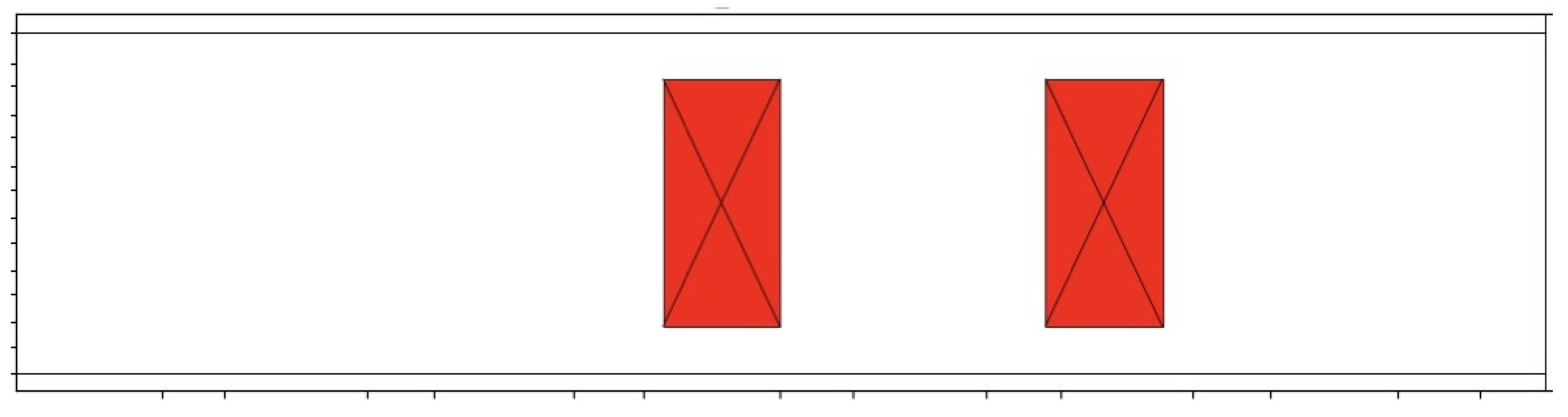
STEP 1: divide the entire facade into floors. A typical floor is shown in
Figure 6.
STEP 2: For each floor, we will use a “dynamic programming” approach: given a floor, we will begin an iteration that will start from the leftmost point of the floor and end at the right end of the floor. At each stage of the iteration, we will try placing a panel of the largest area from the list of available panels, and progressively work towards the smaller ones.
STEP 3: Once we have placed all the panels, we will create the vertical module divisions, that is, the separation that defines the length of each prefabricated module. The length limitation in ENSNARE project is 6 meters, due to the prefabrication processes of the industrial partners. Each module might contain several windows/panels. These module separations need to adhere to certain engineering requirements—there is an upper limit and a lower limit to the module separations.
Figure 6.
An example of a typical facade section from floor to floor. In this case, the floor has two windows (in red).
Figure 6.
An example of a typical facade section from floor to floor. In this case, the floor has two windows (in red).
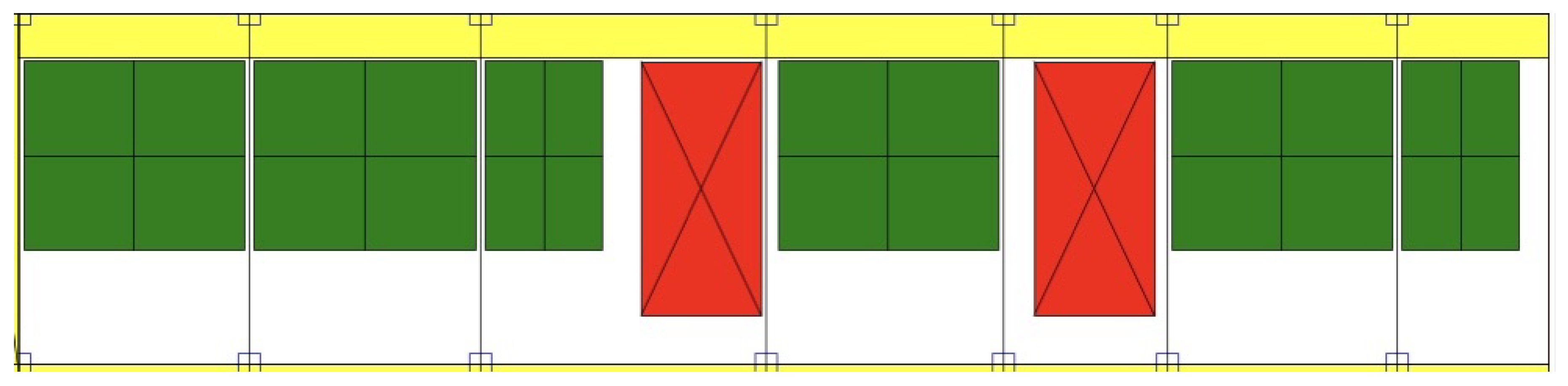
Note that we also need to attach registration areas for the panels. These are the yellow rectangles in
Figure 7. The goal of the registration areas is to host the pipes and cables of the solar panels. Also, if needed, to have the possibility to open and access from the exterior of the facade these pipes and cables, for instance, in case of emergency.
2.4. Pythonic Implementation of Basic Objects
For the purposes of this algorithm, we will be mostly dealing with objects such as windows, panels, registration areas, etc. All of these objects have a certain distinct physical property in common: they are all rectangular. That is, we need precisely four two-tuples to describe every such rectangular object. It is important to note that this rectangular nature is essential for the algorithm. Since the optimization problem is highly geometric in nature, we will be required to implement a wide array of useful geometric properties. We have implemented RectangularObject using dataclasses as described in Listing 6.
The various class properties will be used extensively throughout the code. We have omitted a few class methods in Listing 6 for the sake of brevity. One such class method is intersects (self, cls), described in Listing 7, returns a boolean object to decide if two rectangular objects are intersecting or not:
| Listing 6. The base class for all the rectangular objects that we will encounter in this project. |
![Buildings 13 02981 i008]() |
| Listing 7. Class method to decide if two rectangular objects are intersecting. |
![Buildings 13 02981 i009]() |
Further, the use of dataclasses increases the performance of the code. Other rectangular objects, such as floors, are first of all child classes of the rectangular object class. They might have additional properties, as Listing 8 demonstrates:
| Listing 8. Python implementation of a facade. A facade can consist of floors, panels, windows, etc. |
![Buildings 13 02981 i010]() |
As we will see in later sections, the algorithm will act on a facade object.
2.5. Specific Requirements of the ENSNARE Project
The various modules and panels have to adhere to certain engineering requirements which is essential to the manufacturing process, which is given by the manufacturing partners of the project:
Sizes of the registration areas;
The length of a given module must be at least the MIN_MODULE_LENGTH and at most MAX_MODULE_LENGTH;
The sizes of the inner and outer profile areas;
The panels cannot be of arbitrary size: there is a finite amount of panels of specific lengths and widths.
All this information is contained in the requirements.py file. A typical example is demonstrated in Listing 9 (note that the REQUIREMENTS class also inherits from float, since these are floating point numbers).
| Listing 9. requirements.py, which contains the various manufcaturing requirements. |
![Buildings 13 02981 i011]() |
The facade information, which might comprise floors, windows, and balconies, is provided in the form of a text file. This text file consists of a dictionary, which contains the coordinates of the above-mentioned objects. The general structure of the text file is shown in Listing 10:
| Listing 10. A typical facade text file. We have provided a simplified version for the sake of brevity. |
![Buildings 13 02981 i012]() |
![Buildings 13 02981 i013]() |
Before the main algorithm can do anything, we first need to translate this facade information into Pythonic objects. A helper function that converts this into a JSON object (which Python can understand) is implemented in Listing 11:
| Listing 11. A helper function to convert the text file into a Python dictionary. |
![Buildings 13 02981 i014]() |
Once this is performed, extracting the Pythonic objects from this is fairly straightforward. This is achieved via the function return_facade_from_textfile, which accepts the text file location as an argument and returns a Facade object. This is implemented in Listing 12:
| Listing 12. Function which reads the facade text file and returns a Python Facade object. |
![Buildings 13 02981 i015]() |
2.6. The Main Algorithm I: Placing Panels
The function responsible for placing panels on a given floor is the place_panel function, which accepts a Floor object as an argument and returns an object of the same type. The Floor class, as described in Listing 13, is a child class of the RectangularObject class, with a few further attributes to store the list of windows and panels present on the floor.
| Listing 13. Python implementation of a Floor class. This is a simplified version. |
![Buildings 13 02981 i016]() |
The place_panel function places the panel starting from the left endpoint of the floor. The rate at which it moves along the right is given by the step-size parameter. For the sake of clarity, we have broken this up into several snippets as described in Listings 14–17.
| Listing 14. A snippet of the panel placing function. |
![Buildings 13 02981 i017]() |
At each stage of the iteration, we try to place the panel of the maximum area—this is the greedy approach that we referred to earlier.
| Listing 15. A snippet of the panel placing function. |
![Buildings 13 02981 i018]() |
For each panel, we try to see if it fits at the given position of the iteration: we check if it intersects any windows and panels. We also see if it sticks out of the floor.
| Listing 16. A snippet of the panel placing function. |
![Buildings 13 02981 i019]() |
If it fits, we will add this panel to the list of panels associated with this floor. Otherwise, we discard this panel and see if there are any smaller panels available. If there are no smaller panels available, we move on to the next stage of the iteration.
| Listing 17. A snippet of the panel placing function. |
![Buildings 13 02981 i020]() |
![Buildings 13 02981 i021]() |
2.7. The Main Algorithm II: Placing Modules
Once the panels have been placed, a function called the create_module_seprations tries to create the module separations: it creates the separations using an object called the VerticalSeparator which is implemented in Listing 18. This is simply a vertical line given by the top point, bottom point, and its distance from the y-axis.
| Listing 18. A Vertical Separator. |
![Buildings 13 02981 i022]() |
The create_module_seprations, described in Listing 19, first collects the left/right endpoints of the windows and panels present on the floor.
| Listing 19. A snippet of the create_vertical_separations function. |
![Buildings 13 02981 i023]() |
From this list, the function attempts to create pairings (where x and y are members of this list) in such a way that the following three conditions are satisfied:
This is implemented in Listing 20 shown below:
| Listing 20. A snippet of the create_vertical_separations function. |
![Buildings 13 02981 i024]() |
![Buildings 13 02981 i025]() |
So far, the algorithm acts on each floor: it places the panels then it places the modules (i.e., the vertical separations). Once this is performed for each floor, we can combine them to obtain a panel placement on the entire facade.
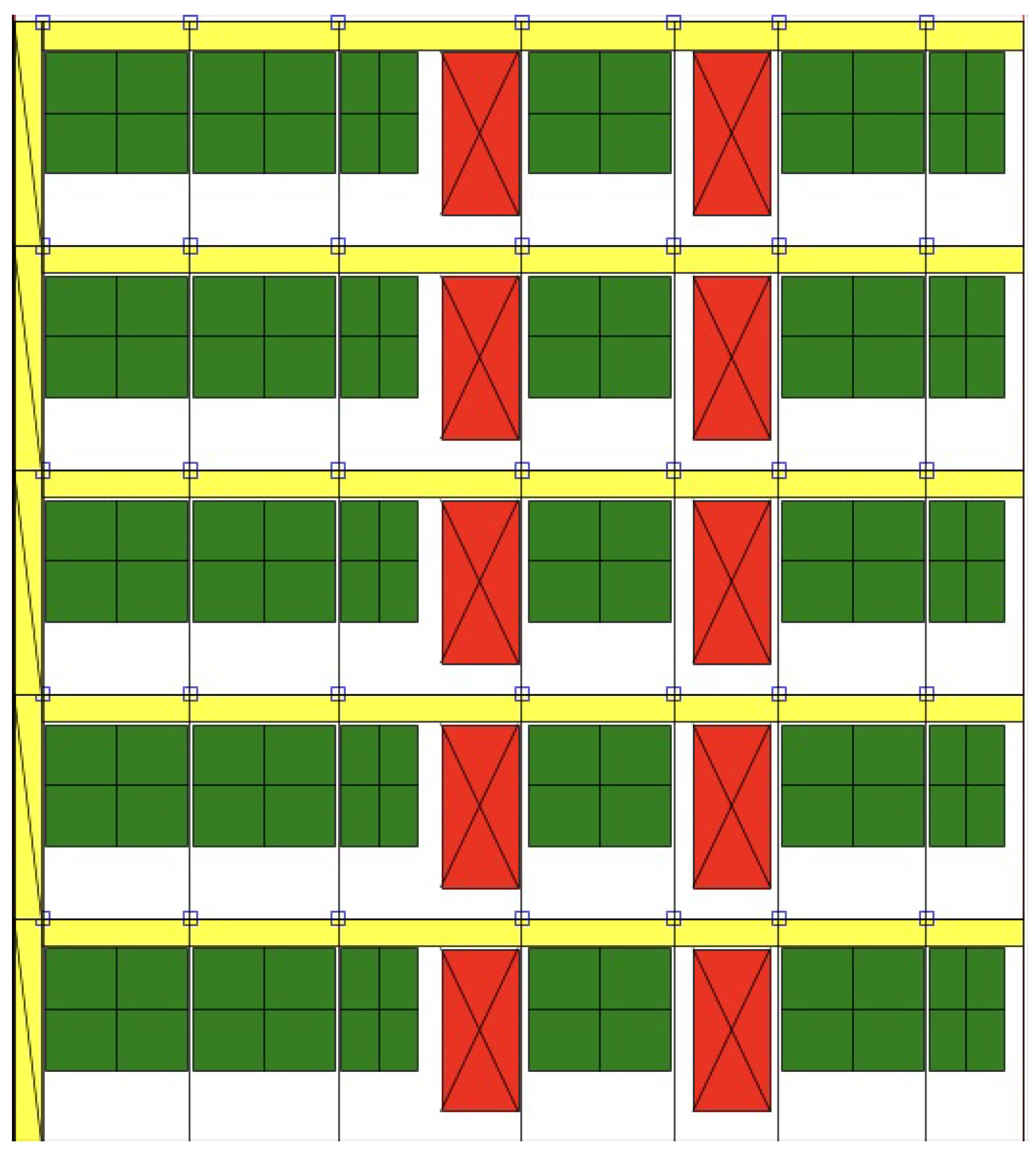
2.8. Generating Outputs
The output of the solar panel maximization algorithm generates a visual plot of the entire facade. This is achieved using Matplotlib (see
Figure 8).
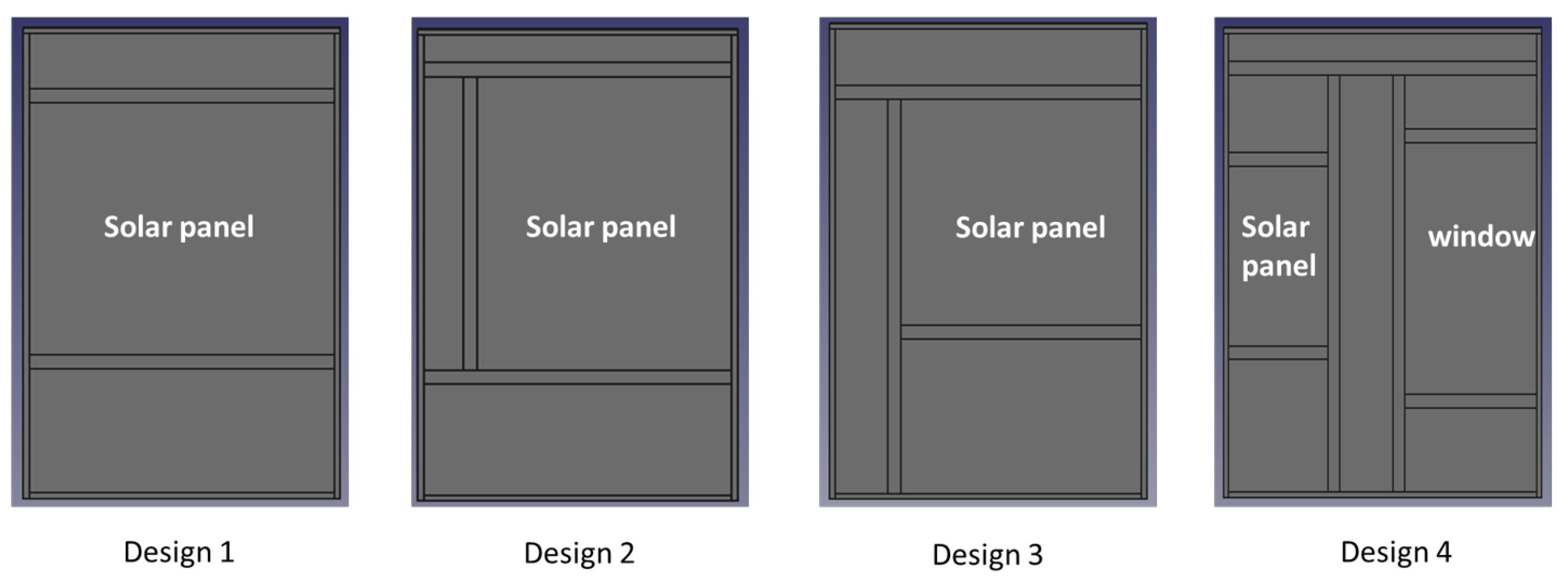
It is also possible to generate a JSON file providing detailed information regarding the 2D coordinates of each module and panel in the facade. Currently, four different designs of prefabricated modules are being used in the project as shown in
Figure 9.
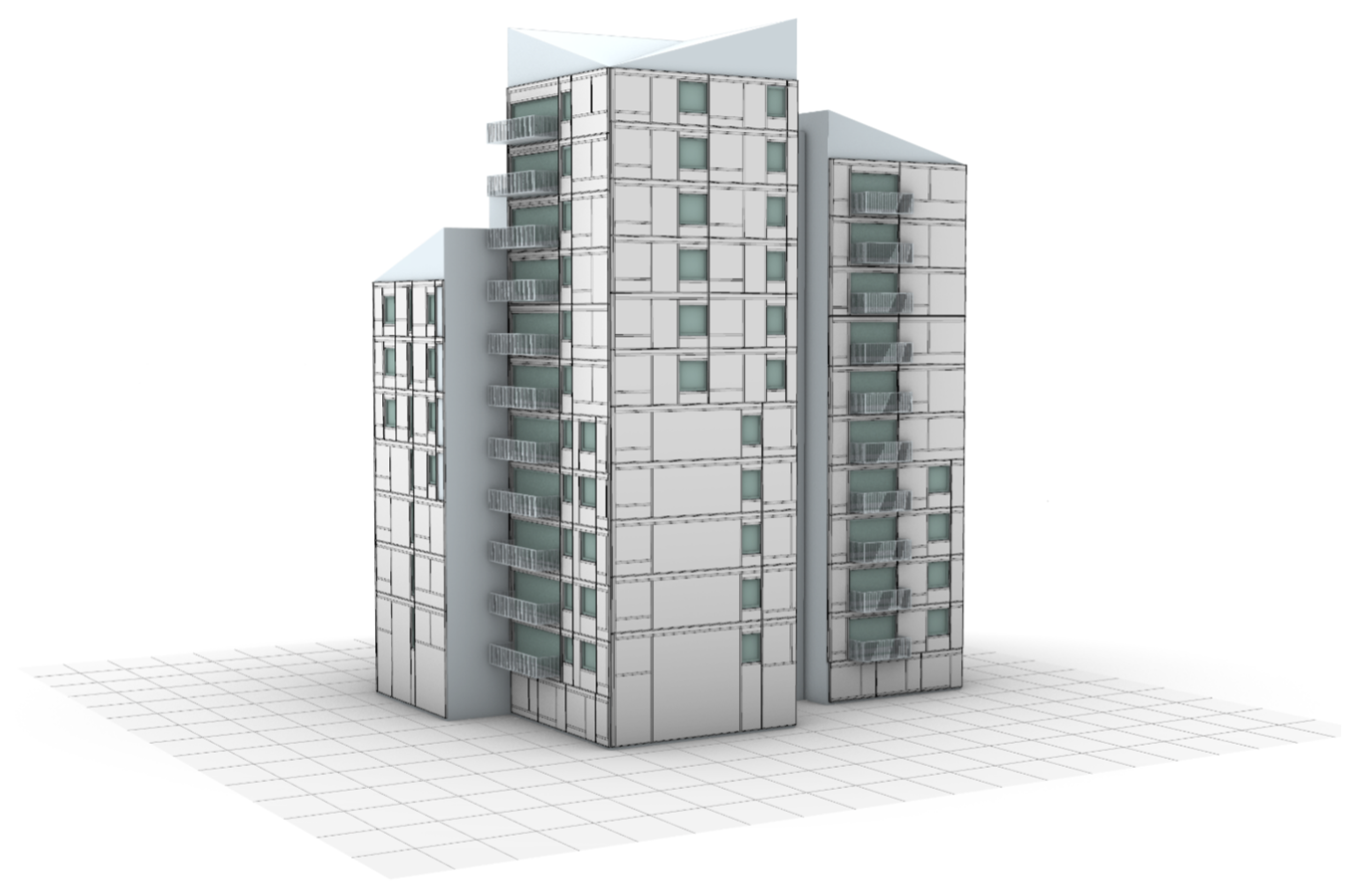
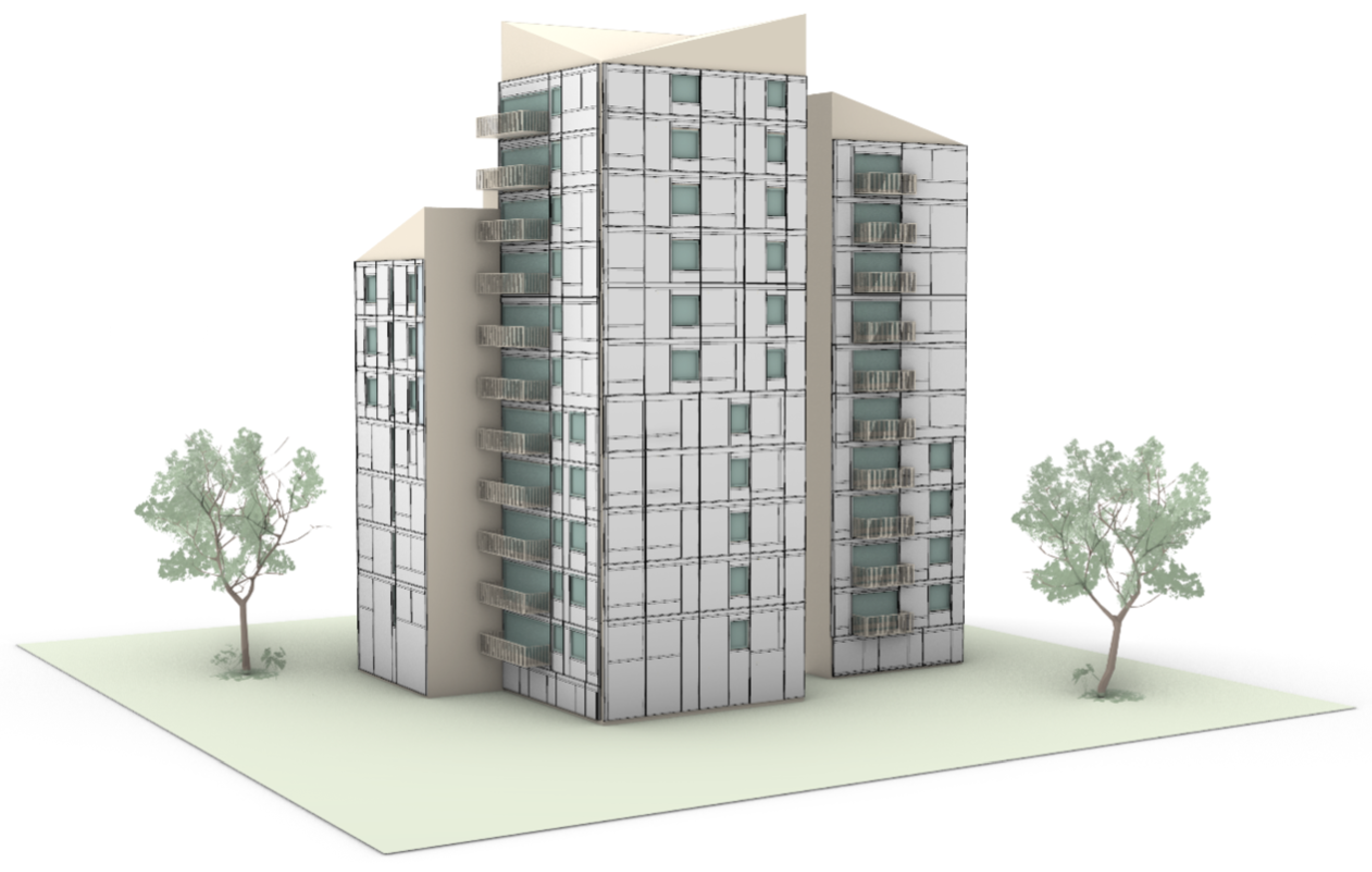
Comparing the module and panel dimensions from the data generated by the algorithm, the most appropriate design (out of the four available designs) is chosen. These four designs are hard-coded using simply Python and FreeCAD tools. Now, the 3D projection algorithm is applied and the already existing 3D model in FreeCAD now gets updated by the solar panel modules as shown in
Figure 10.
Furthermore, two Excel files are generated as well. One of them provides the connector positions corresponding to each module and window in the facade. The other file provides intricate details regarding the dimensions of each component of each module in the facade, which are essential for robotic assembly. These data can also provide a total manufacturing cost estimate for the project.
3. Addressing RG1.4 by Re-Configuring the Layout of the Prefabricated Modules
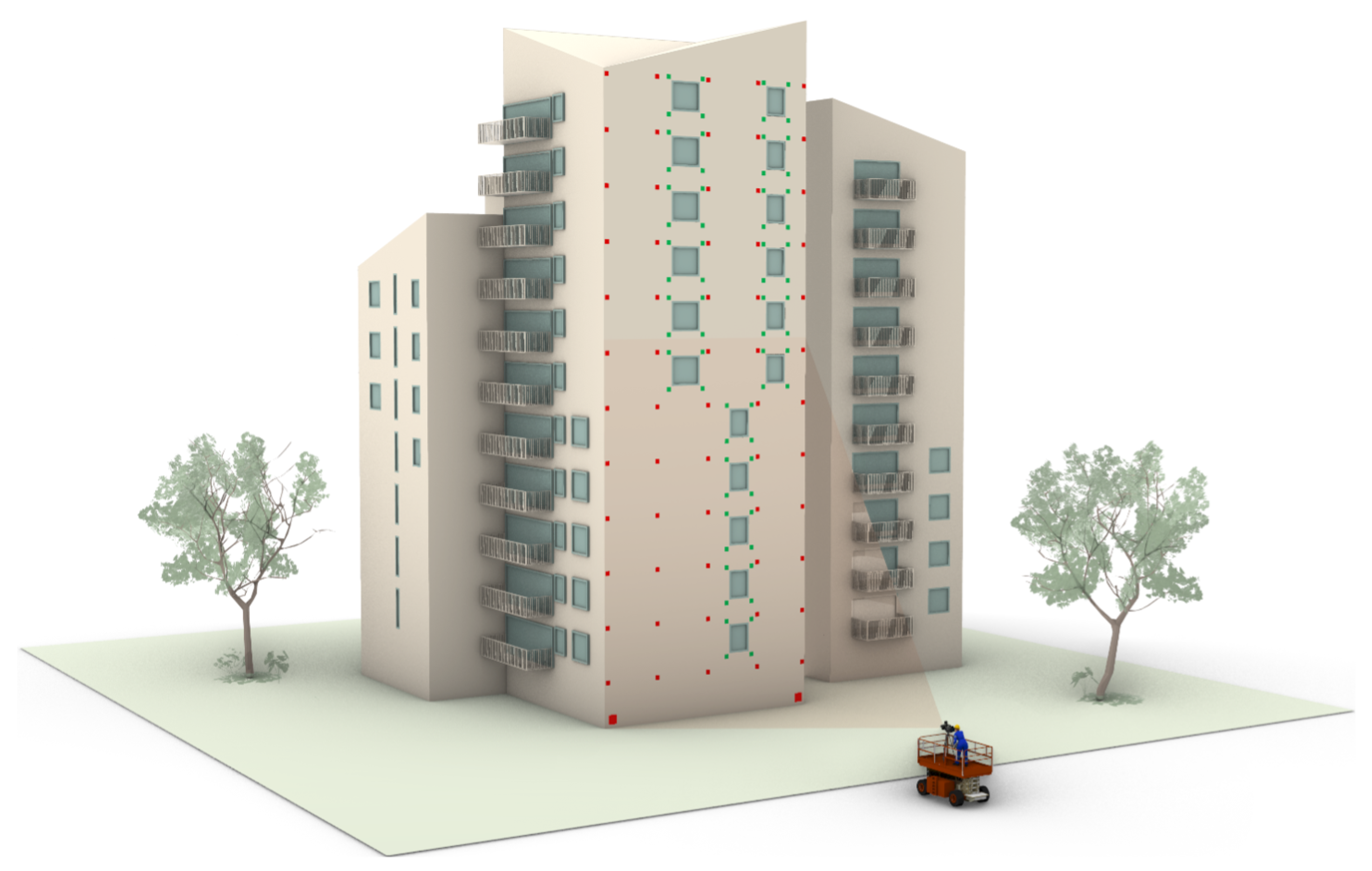
In the next step of the building renovation project, the engineering team visits the site and obtains accurate measurements of the building. The technique used in the ENSNARE project is based on using targets on the critical parts of the building, such as the location of the connectors, windows, and other building edges. Once the engineering team has measured the location of the targets (see
Figure 11), the building model measurements need to be readjusted, and accordingly, the layout of the prefabricated modules too.
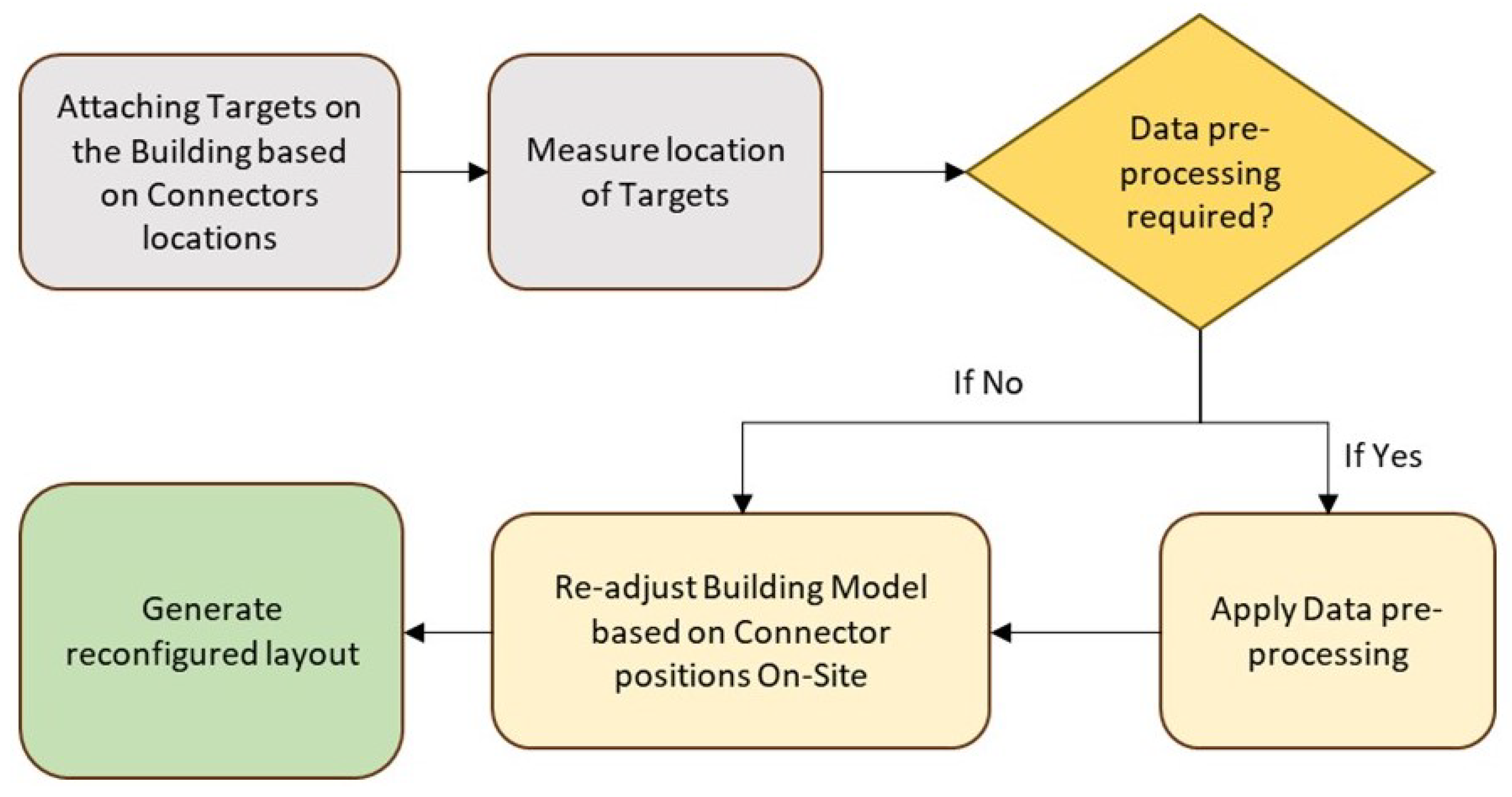
Adjusting the layout of prefabricated modules manually is time-consuming work. The Flowchart described in
Figure 12 describes the automated steps to reduce this time.
Data pre-processing may be necessary depending on the structure and orientation of the data provided. The pre-processing steps taken may include generating a transformation matrix to multiply the provided data and transform it into a form compatible with the algorithm. Additionally, it is important to note that the connector positions are provided, rather than the actual window positions on the facade. As a result, it is necessary to determine the correct window dimensions and positions before applying the algorithm. This is achieved by subtracting or adding the connector offset length to the provided data in order to derive the required positions and dimensions of windows.
In order to generate the text file with correct information, the following functions were implemented:
1. First, the data provided needed to be converted into 2D because otherwise the algorithm cannot be applied. Hence, the slope of the facade is determined, along with its width, height, and floors from the provided data. This is achieved through Listing 21 shown below:
| Listing 21. A Python function which determines the facade slope. |
![Buildings 13 02981 i026]() |
![Buildings 13 02981 i027]() |
2. Then, the window list is generated, as shown in Listing 22, from the provided data through the code shown below. Once this window and other important information pertaining to the facade width, height, and floors have been obtained, the text file is generated in order to apply the algorithm.
| Listing 22. A Python function which generates a text file containing the list of windows. |
![Buildings 13 02981 i028]() |
![Buildings 13 02981 i029]() |
![Buildings 13 02981 i030]() |
It must be said that the prefabricated module layout is as detailed as for being used for manufacturing purposes, including profiles, enclosure boards, insulation and, of course, solar panels (see
Figure 13).
4. Tests and Results of the Solutions
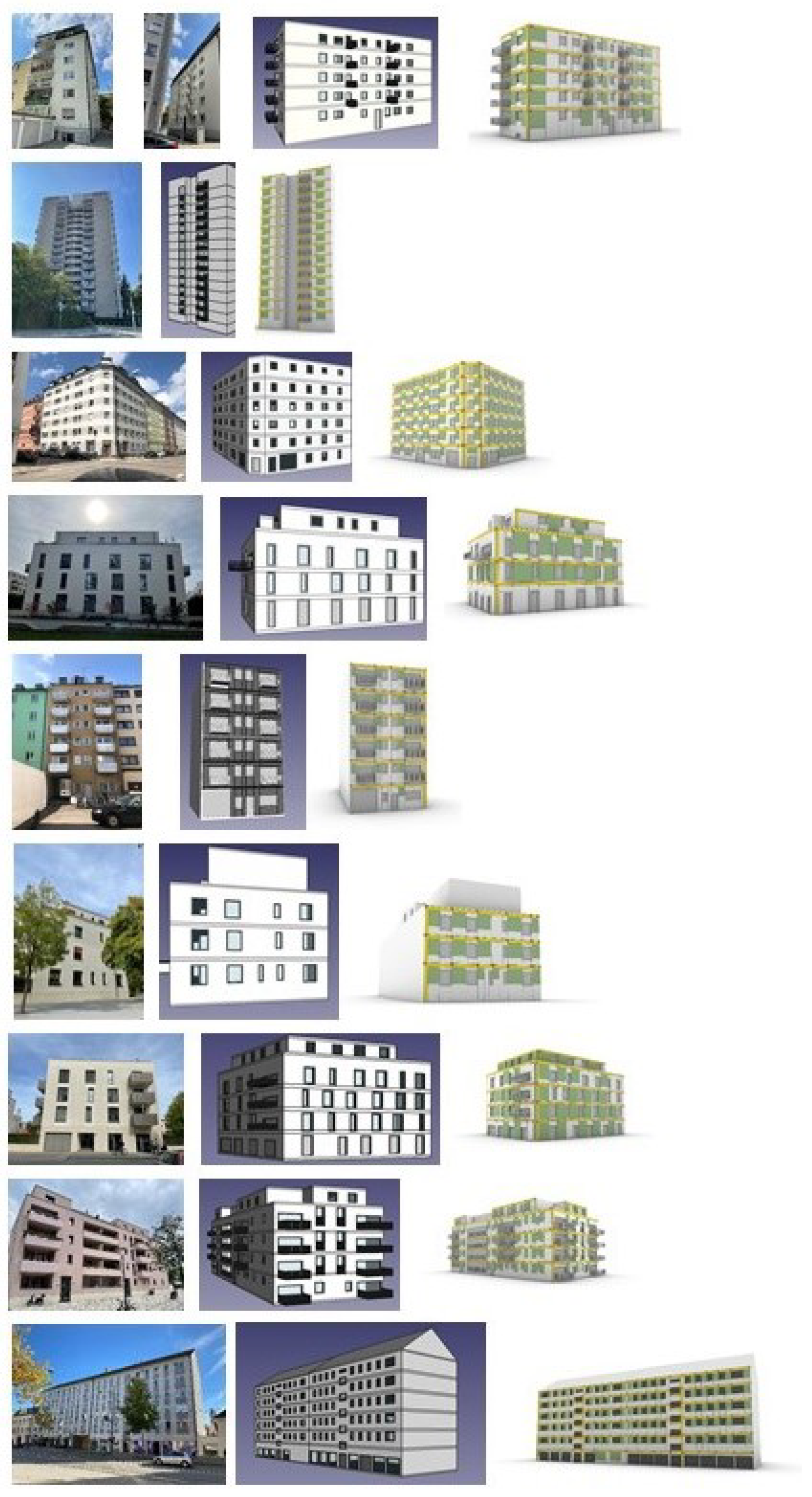
The main objective of the solutions was to reduce time. In order to test the efficiency of the solutions, up to 10 residential buildings have been used to test the aforementioned tools, as explained in
Figure 14. Applying the algorithm takes a few minutes, depending on the complexity of the building.
As an example, a complex residential building like the demo building in Milan, which has approximately 3000 m² of building envelope was monitored. Defining the prefabricated layout manually can take up to 1020 h (0.34 × 3000) according to previous manual tests [
23]. With the solutions described in this paper, it can take about 25 min in each of the steps (RG 1.2 and RG 1.4).
With this technique, the arduous work of defining the layout of prefabricated modules for facade renovation can be reduced to a minimum. By utilizing these tools, residential building owners, promoters, and engineers can make informed decisions regarding the installation of prefabricated modules with solar panels, thereby ensuring that the renovation project is both economically viable and energy-efficient.
5. Conclusions and Further Developments
The results described in this paper have successfully addressed the research gaps RG1.2 and RG1.4. The time consumed for generating the prefabricated facade module layout is minimal with a commercial and updated computer/processor.
The various tools and techniques introduced will help semi-automate the process of making buildings more energy efficient. Future research will include:
Improving the optimization algorithm. Currently, there are certain facades where the algorithm performs poorly. This can be circumvented by trying a different approach, instead of the greedy approach as discussed in this paper. It is possible to re-formulate this problem as an optimal packing problem [
26,
27].
As discussed before, the methods discussed in this paper have not been fully extended to include more diverse building types, such as buildings with pitched roofs. This is one possible avenue for further advancements.
As a final conclusion, it must be commented that the techniques described in this paper will be integrated with an online tool that will include not only the techniques in RG1.1, RG1.2, and RG1.3, but also energy calculations. All this will contribute to reducing the energy consumption of the residential building stock. However, it must be said that these automated procedures developed in RG1.2 and RG1.4 cannot exchange the experience and knowledge of human designers. Aesthetic criteria, for instance, is not considered yet. Therefore, the designs and layouts must always be supervised and, if needed, amended.

 ,
, 


