1. Introduction
In recent years, with the vigorous development of global infrastructure construction, tunnel construction technology has witnessed unprecedented rapid advancement. In the meantime, tunnel construction is facing the challenges of complex geological conditions and difficult construction environments [
1], which demand not only innovative engineering techniques but also improvements in construction equipment and comprehensive solutions [
1]. As a key technology of tunnel construction, the slurry shield method combines a shield machine with a mud circulation system to realize the tunnel excavation and tunnel support at the same time so as to provide substantial support for urban development and infrastructure construction [
2]. Slurry shield technology boasts significant advantages in tunnel engineering. Firstly, in comparison with traditional blasting methods, slurry shield tunneling technology avoids issues such as noise and vibrations, which can effectively reduce the impact on the surrounding environment and structures. Secondly, continuous excavation and support can be carried out during the construction of a slurry shield, which can improve construction efficiency and shorten the project period [
3]. Of particular significance, the mud pump plays a critical role in slurry shield tunneling construction; it is responsible for transporting mud from the surface to the tunnel construction site and sustaining the circulation and stability of mud throughout the tunnel excavation process. However, with the continuous expansion of the construction scale and the increasingly complex geological conditions, the demand for mud pumps has steadily increased [
4,
5,
6]. Therefore, ensuring normal operation under more complex geological conditions, enhancing discharge efficiency to adapt to larger-scale construction, and reducing energy consumption are all pressing issues that need to be solved for the mud pump. However, under high-pressure and high-frequency reciprocation, a significant amount of frictional heat will be generated in the piston of the mud pump, influenced by both surface frictional heat and internal frictional heat, the piston’s wear resistance deteriorates sharply, which leads to a loss of piston sealing capability, and resulting in sand particles in the mud easily infiltrating into the gap between the piston and the cylinder. Eventually, not only the rubber piston will be damaged, but also the cylinder will be worn and scratched [
7,
8,
9,
10]. Consequently, enhancing the frictional wear performance of the mud pump piston has become a pressing issue that requires immediate attention.
To enhance the wear resistance of mud pump pistons, researchers both domestically and internationally have conducted relevant studies from the perspectives of material and structural optimization. Regarding material optimization, as early as the 1990s, scholars began investigating the use of modified materials such as MoS
2, fiberglass, and graphite to improve the wear reduction and wear-resistant properties of pistons [
11]. Wang [
12] pointed out that the use of a composite structure with rubber and fabric reinforcement layers, as well as utilizing a multi-layered composite rubber-coated fabric strengthening layer at the base of the piston, is advantageous for enhancing the pressure resistance and wear resistance of the piston. Mu et al. [
13] incorporated MoS
2 into the piston rubber material to reduce the friction coefficient of the piston and optimize its wear resistance. Burov et al. [
14] proposed the use of a polyurethane material instead of rubber material, which is conducive to reducing the friction coefficient of the piston and enhancing its wear resistance. Karnaukhov et al. [
15] indicated that the supporting and sealing components of the piston should be made of materials with different hardness values. The supporting components should have higher hardness, disregarding their elasticity, to withstand the primary deformation caused by the settling of abrasive grain and reduce the load on the sealing components.
Based on current research, there is relatively limited study regarding the improvement of materials for mud pump pistons. Due to numerous constraining factors, achieving significant breakthroughs in the realm of materials appears to be challenging. Nevertheless, as the field of biomimetics advances, researchers embarked on deriving inspiration from natural organisms and proposed the biomimetic non-smooth design for piston surfaces by analyzing the characteristics of drag reduction, anti-adhesion, and wear resistance of the bionic non-smooth surface of natural organisms [
16,
17]. Etsion et al. [
18,
19,
20] proposed that the sealing and wear resistance will be better by applying non-smooth surfaces to different lubricating mechanical parts (especially sealing devices and piston rings). Ryk et al. [
21,
22] stated that the piston ring with partial surface texture can reduce friction by about 25% compared with the conventional cylindrical piston ring. Wu et al. [
23,
24] studied that the design of bionic structures of pits and through-holes on the surface of internal combustion engine pistons can play the role of oil storage, chip storage, and lubrication improvement and can unload the concentrated stress in the piston oil ring groove. Zheng et al. [
25] pointed out that the bionic structure of hardness gradient and hexagonal texture is beneficial to improve wear resistance and provide a new strategy for the wear and friction management of pistons. Cheng et al. [
26] indicated that striped-shape structures can alter the stress distribution on the working surface of the piston, enhance the storage space for lubricating oil, improve the wear resistance of the piston, and reduce squeeze damage to the root of the piston. Gao et al. [
27,
28] pointed out that designing cylindrical dimples on the piston surface can decrease the flow velocity of lubricating oil, elevate oil film pressure, and these dimples can function as reservoirs for lubricating oil, providing secondary lubrication to the friction pair interface. Zhang et al. [
29] noted that groove structures are beneficial for enhancing the sealing performance of the piston, but it will lead to additional bending stress; specifically, the mechanical properties of the triangular groove structure are better than those of other groove structures. Guo et al. [
30] indicated that reasonable bionic pit parameters can significantly improve the service life of the piston; for the bionic structure with a pit shape, the pit diameter has the greatest influence on the life of the piston, while the pit depth has the least influence. Maddox et al. [
31] designed a surface texture consisting of dimples and grooves arranged in elongated hexagon shapes on the piston surface, which can reduce the friction coefficient of the piston surface by an average of 18% compared with the flat surface.
In summary, it is more effective and convenient to improve the performance of the piston by optimizing its shape. However, previous studies mainly focused on the stress distribution on the piston surface through static mechanical analysis, which ignored the influence of friction heat on the strength and wear resistance of the piston; the research results have certain limitations. Therefore, inspired by the surface features of biological entities in nature, the bionic design of a mud pump piston was proposed. The stress field and temperature field of the bionic piston were analyzed using the finite element method. The optimal bionic surface morphology and structural parameters of the piston were determined, thereby providing theoretical support for the design of a high-performance mud pump piston.
2. Design of Bionic Morphology for Mud Pump Pistons
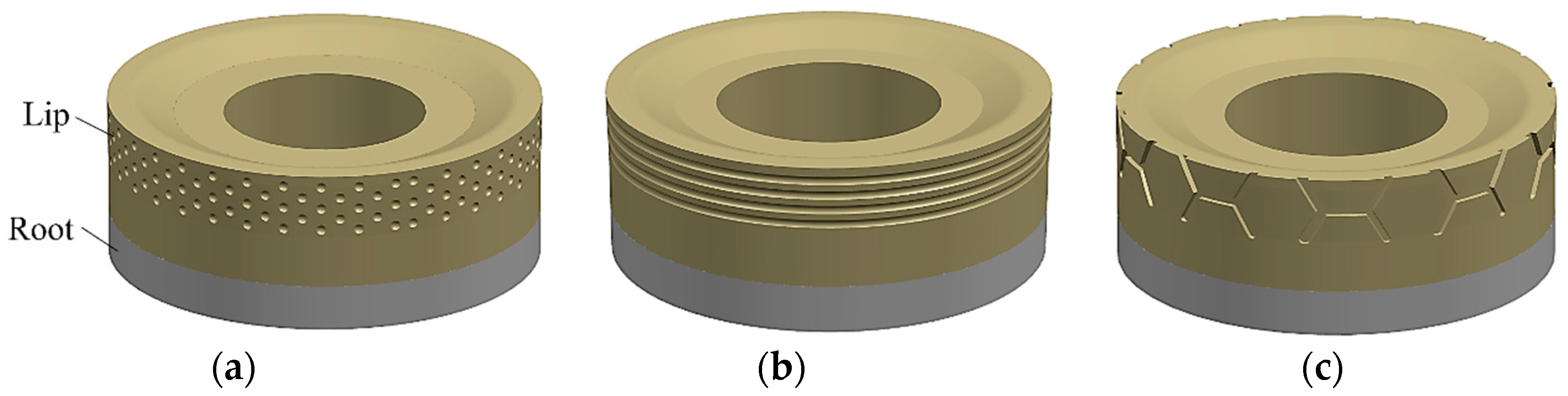
In the operational process of a mud pump, the piston and cylinder experience repetitive frictional contact, which can lead to wear of the piston and cylinder. The bionic piston comprises a rubber lip section and a nylon root section. The rubber lip section engages in interference contact with the cylinder, while the nylon root section primarily serves protective and transitional functions. As a result, significant emphasis is placed on the biomimetic non-smooth morphology design of the piston lip section.
For the dung beetle, the pit shape morphology on its surface reduces its contact area with the soil, consequently lowering soil adhesion forces; simultaneously, the air stored within these dimples generates localized negative pressure, which serves to counteract a certain level of contact pressure, which achieves the purpose of reducing resistance [
32]. For the earthworm, its surface is comprised of multiple stripe shape segments; during its crawling process within the soil, these segments exhibit flexible twisting and extension, creating a non-smooth, undulating wave-like pattern, effectively reducing the contact area with the soil and thereby lowering frictional resistance [
33,
34]. For the lizard inhabiting desert regions, its surface is covered by multi-layered skin, and the skin is closely embedded to form rhomboidal scales, which can effectively reduce the contact area between the body surface and the ground, leading to a reduction in frictional resistance [
35]. The surface structures of the dung beetle, earthworm, and lizard are depicted in
Figure 1.
Therefore, taking inspiration from the biological prototypes of beetles, earthworms, and lizards, three biomimetic structural forms were designed for the piston lip: pit shape, stripe shape, and prismatic shape, as illustrated in
Figure 2.
Using the Abaqus 6.14 finite element analysis software, stress and temperature field analyses were conducted on the three biomimetic piston structures, aiming to identify the optimal biomimetic morphology.
3. Stress Field Simulation Analysis of a Mud Pump Piston
The sealing and friction-wear performance of the piston is primarily influenced by the contact stress between the piston and the inner wall of the cylinder. Therefore, stress field analyses were performed on pistons with pit shape, stripe shape, and prismatic shape biomimetic structures, respectively, to determine the optimal biomimetic structural morphology.
3.1. Preprocessing for Simulation
The reciprocating motion of the mud pump piston within the cylinder was simulated and analyzed using the Abaqus finite element software. Given the complex operating conditions of the cylinder friction pair in practical scenarios, the following assumptions were made to ensure the smooth progress of the simulation: ① The friction pair of the cylinder was treated as an ideal axisymmetric model. ② The materials used for various components, including the piston and the cylinder, are considered continuous, uniform, and isotropic. ③ The material of the piston was uniformly defined as polyurethane rubber.
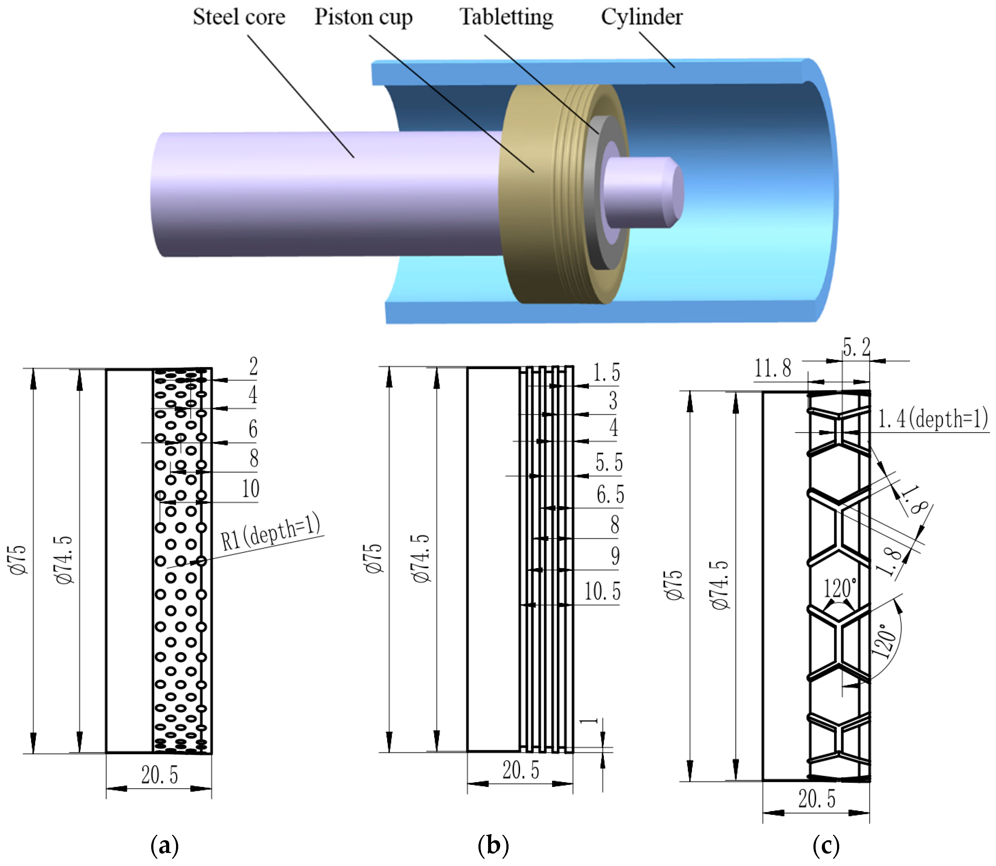
The three-dimensional simulation model of the mud pump piston–cylinder friction pair and the piston parameters are depicted in
Figure 3. The materials used for the cylinder, tableting, and steel core were 45 steel, with an elastic modulus of 210 GPa, a Poisson’s ratio of 0.3, and a density of 7800 kg/m
3. The piston material was defined as a hyperelastic rubber with a density of 1120 kg/m
3. The material was characterized using a two-parameter Mooney–Rivlin model [
36]. The physical properties in this model were mainly expressed by the strain energy function, that is
where
W is the strain energy function;
C10 and
C01 are Rivil coefficients, they are positive definite constants; in this work,
C10 = 2.5 Mpa and
C01 = 0.625 MPa;
I1 and
I2 are the second and third green strain invariants;
J is the volume ratio;
D1 is the incompressibility parameter of the material; in this work,
D1 = 0.032 MPa
−1 [
28].
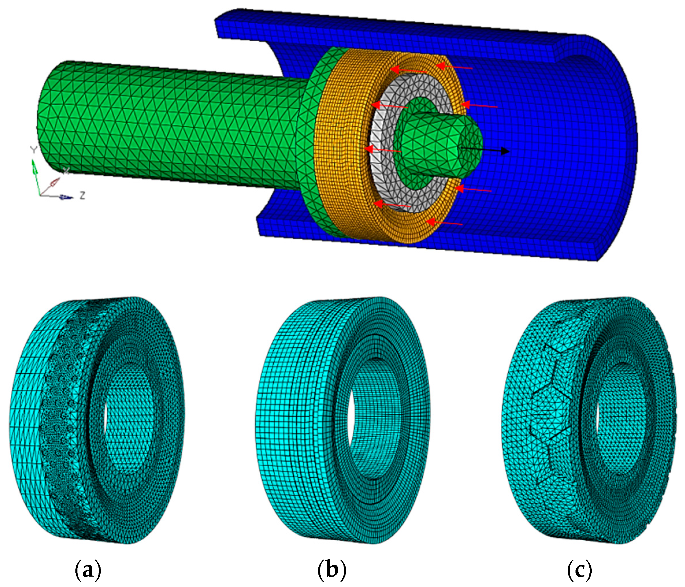
A contacting friction pair was formed between the piston and the inner wall. To enhance computational accuracy, the outer surface of the piston was subjected to mesh refinement. The mesh elements were defined using the C3D8H cell type, with a minimum grid size controlled at 1.5 mm.
Figure 4 depicts the mesh division model of the mud pump piston–cylinder friction pair.
Two sets of frictional contact pairs were employed for the analysis: the piston–cylinder friction pair and the piston–steel core friction pair. The frictional contact algorithm utilized for the former was the augmented Lagrangian method, with a friction coefficient of 0.37. For the latter, there was no gap between the piston and the steel core, thus defining a non-separating interface between them. The piston underwent reciprocating motion driven by the steel core, while the tableting was integrated with the steel core. Full fixed constraints were applied at both ends of the cylinder. Additionally, the movement of the piston and steel core was restricted in all directions except for the axial displacement direction.
The motion analysis of the piston within the cylinder liner was conducted in three loading steps: ① Simulating the piston’s interference fit within the cylinder aimed to achieve initial sealing. ② Keeping the cylinder, piston, steel core, and tableting static, with the premise of initial preloading force, the working pressure of 6 MPa was uniformly applied on the right end face of the piston in contact with the mud, as indicated by the red arrow in
Figure 4. ③ Applying a stroke displacement along the positive direction of
Z-axis to the piston to simulate the process of mud discharging (shown by the black arrow in
Figure 4).
Figure 5 shows the loading curve of the analysis step.
The following analysis was based on the completion of the third loading step, that is, the piston reciprocated in the positive direction of the Z-axis for one cycle (corresponding time is 0.02 s).
3.2. Analysis of Stress Fields in Different Bionic Structure Pistons
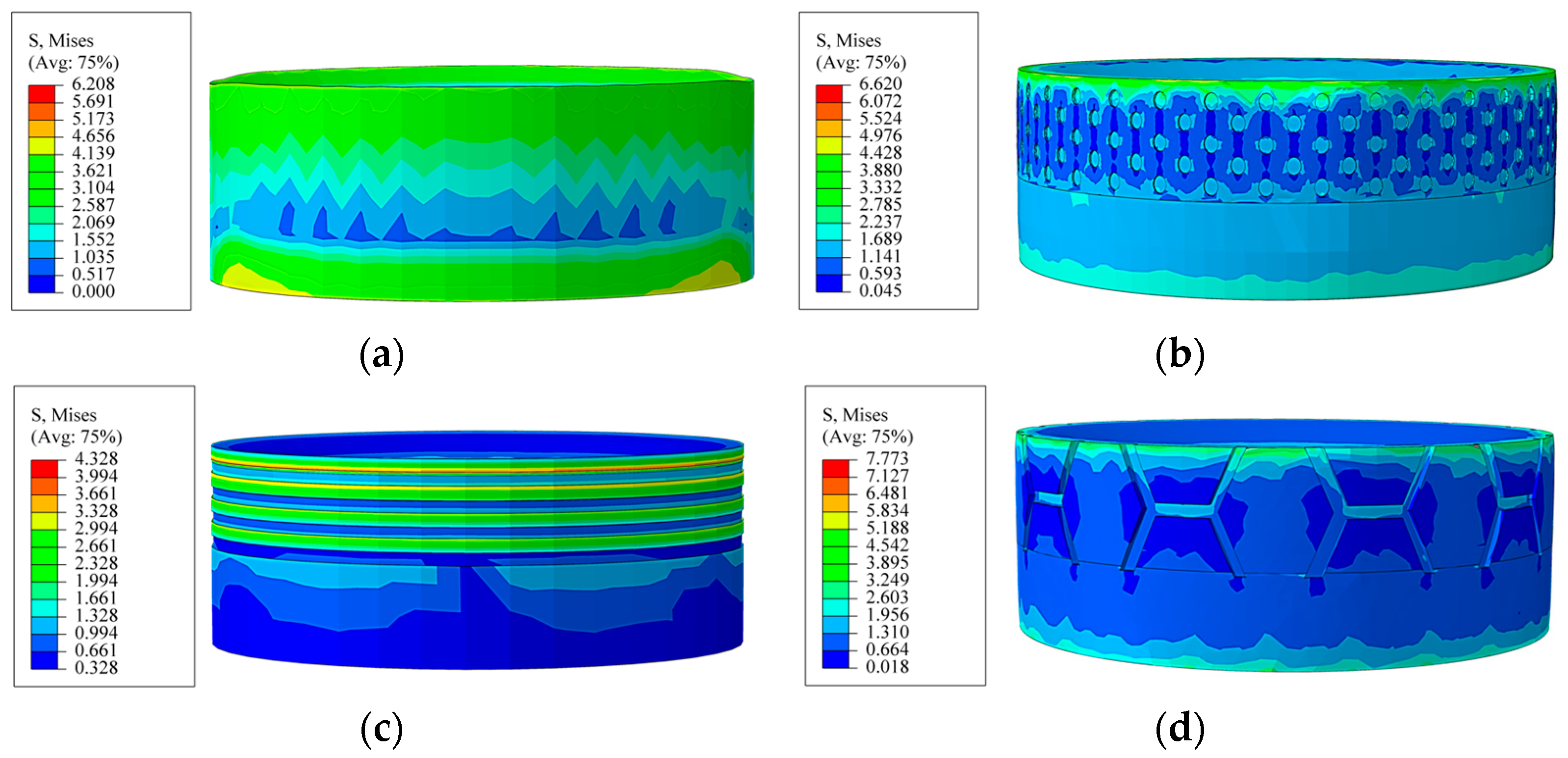
Based on the simulation results, taking a traditional planar piston as a reference, the stress distribution characteristics of the four pistons, planar shape, pit shape, stripe shape, and prismatic shape were analyzed.
Figure 6 illustrates the von Mises stress contour plots of the four kinds of pistons.
Analyzing
Figure 6, the stress distribution area on the surface of the planar-shaped piston was large, the maximum stress was concentrated at the lip and the root, and the lip of the planar-shaped piston was slightly deformed. The prismatic-shaped piston experienced relatively higher von Mises stress values; these stresses were concentrated primarily at the lip and the root, making the root susceptible to squeeze damage, which accelerated the wear of the piston. The maximum equivalent stress of the pit-shaped piston occurred at the lip region and the interior of the pit array near the bottom of the pit. This pit configuration facilitated the absorption of partial stress through microstrains at the pit locations; however, the stress on the root of this structure was relatively high. The von Mises stress of the stripe-shaped piston was distributed on both sides of the stripe structure (which was consistent with the conclusion given in reference [
26,
29]), significantly reducing stress at the root and minimizing the occurrence of root fractures; the maximum equivalent stress occurred at the elevated portion between the stripes.
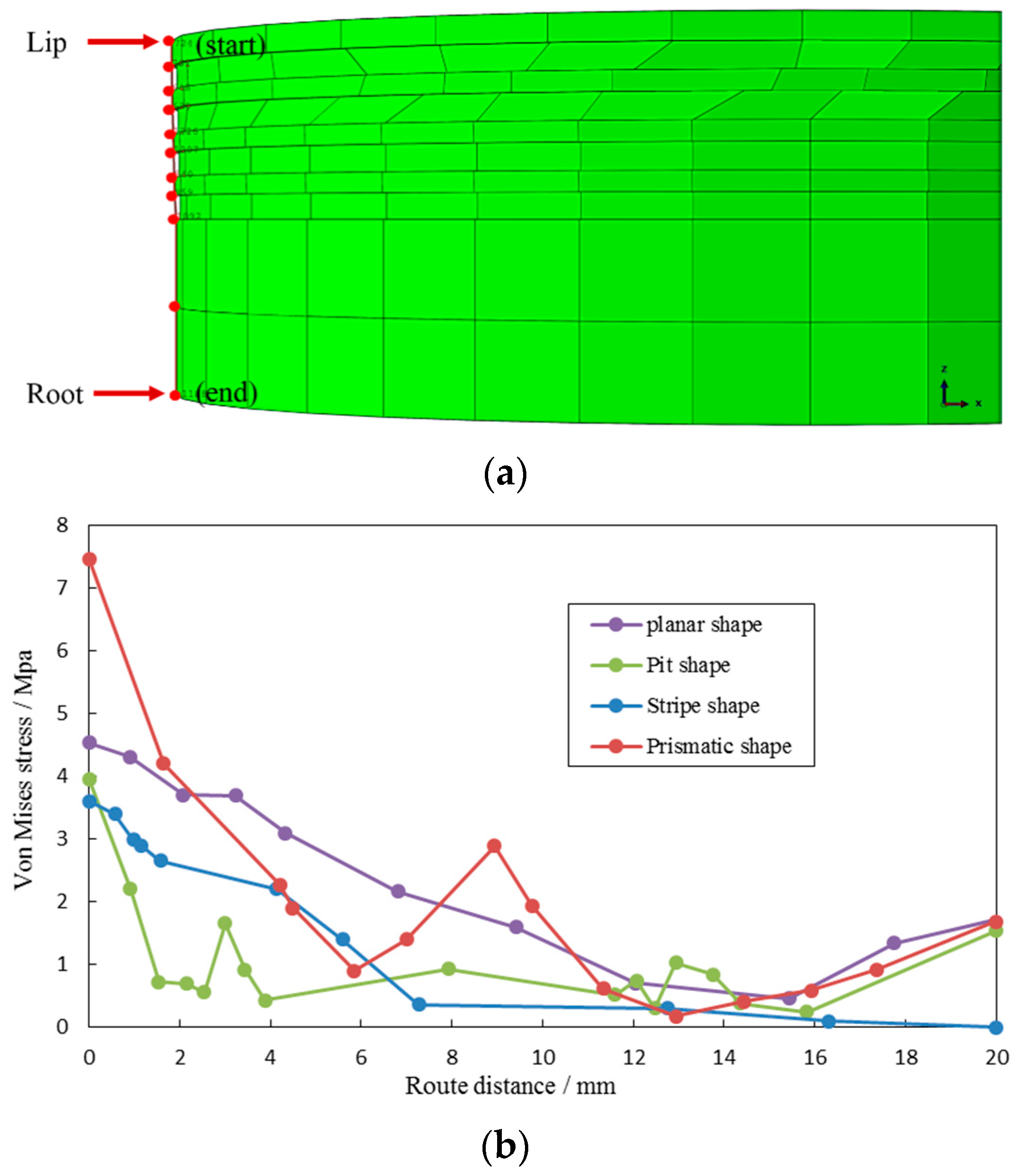
A group of nodes was selected along the piston axis from the lip to the root, and a path of nodes was created. This path was used to plot the variation of von Mises stress along the axis, as depicted in
Figure 7.
Analyzing
Figure 7, it can be observed that from the lip region to the root, there was an overall decreasing trend in the von Mises stress on the surfaces of the four structure pistons. In particular, the planar shape, pit shape, and prismatic shape pistons experienced stress rebound at the root, leading to an increase in stress. Under real working conditions, the lip tends to experience a centripetal effect under pressure, resulting in distortion and a lack of close contact with the cylinder wall, and the stress values at the lip area are significantly reduced. Conversely, the phenomenon of stress concentration at the root will become more pronounced and evident, often leading to squeeze damage. Therefore, special attention should be given to the root, which represents a critical weak point. Under the application of identical pressure loads, the surface stress variation of the stripe-shaped bionic piston remained relatively stable; there were no nodes exhibiting abrupt increases or decreases in stress, and the stress at the root was the lowest among the three structures. Hence, optimizing the stripe-shaped structure as the final scheme for the bionic piston can effectively reduce the stress variation gradient on the piston surface, safeguard the root, and mitigate the risk of surface damage to the piston.
3.3. Parameter Optimization of a Stripe-Shaped Bionic Piston Based on Stress Analysis
In
Section 3.2, the optimal bionic piston structure, namely the stripe-shaped bionic piston, was obtained. Subsequently, an optimization design was conducted for the stripe width parameter. Four sets of structural schemes with stripe widths of 0.5 mm, 1 mm, 1.5 mm, and 2 mm were designed, respectively. Stress field simulation analyses were performed on these schemes.
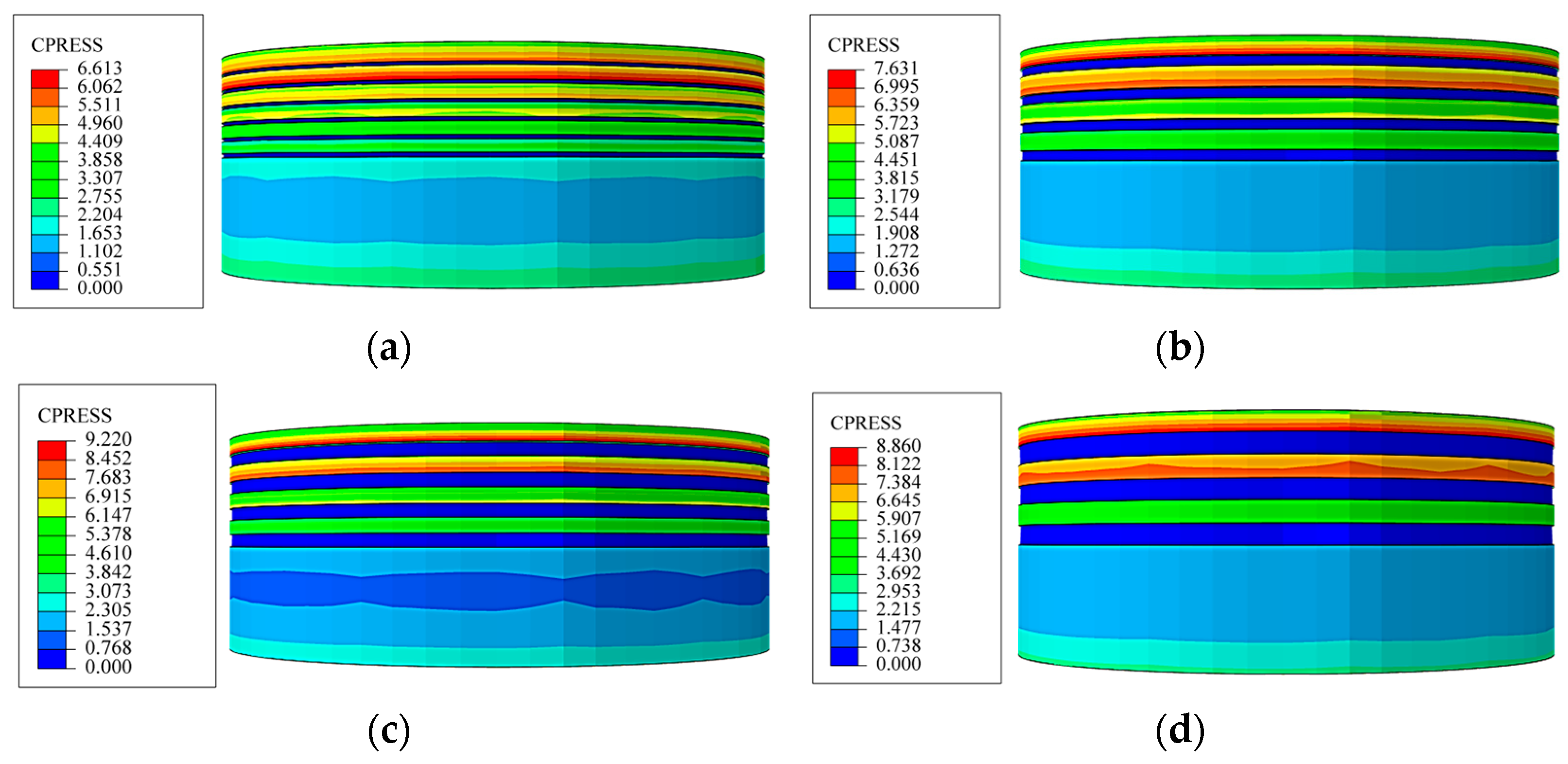
Figure 8 illustrates the contact stress contour maps of the bionic pistons with different stripe widths.
From
Figure 8, it can be observed that the maximum contact stress of the stripe-shaped piston was located in the elevated area between adjacent stripes. When the stripe width was less than or equal to 1.5 mm, with the increase in stripe width, the maximum contact stress gradually increased. However, when the stripe width was 2 mm, the maximum contact stress slightly decreased.
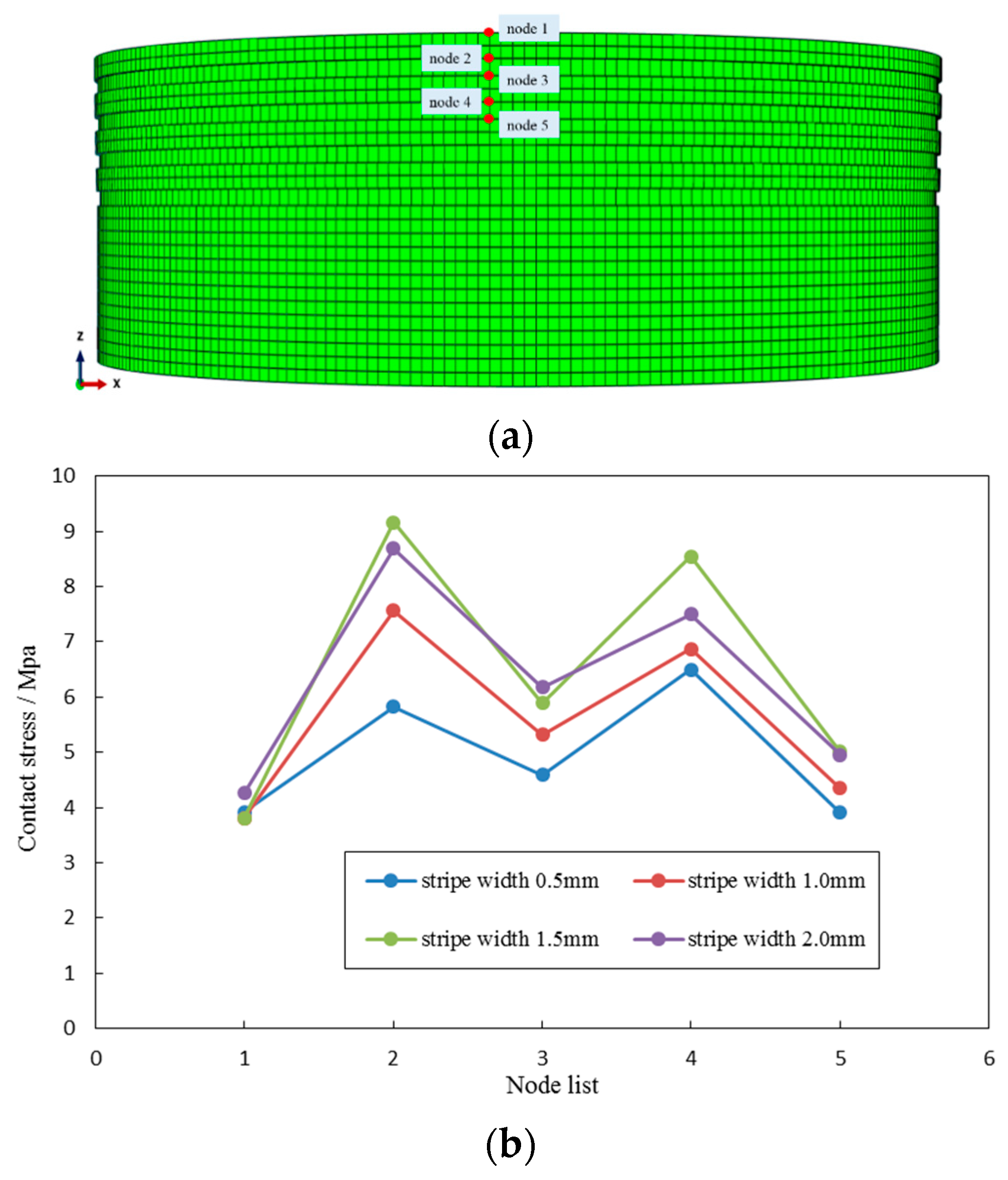
Once the mud entered the piston–cylinder friction pair from the lip of the piston, it accelerated the piston’s wear, leading to piston failure. Hence, the focus was placed on the analysis of contact stress characteristics at the lip of the piston. For the lip of the stripe-shaped piston, five nodes were selected along the piston’s axial direction. The contact stress values at these five nodes were extracted and plotted to form a curve, as depicted in
Figure 9.
The greater the contact stress on the piston surface, the smaller the gap between the piston and the cylinder. This led to more effective prevention of mud from entering the piston–cylinder friction pair. As observed from
Figure 9, when the stripe width was between 1.5 mm and 2 mm, the contact stress on the piston surface was relatively high, resulting in better sealing performance.
Figure 10 presents von Mises stress contour maps for four sets of stripe-width bionic pistons.
Since the root is a vulnerable part of the piston, a comparative analysis of the von Mises stress distribution at the piston root is of particular significance. As evident from
Figure 10, the von Mises stress was minimized at the piston root when the stripe width was 1.5 mm. For the root of the stripe-shaped piston, five nodes were selected along the piston’s axial direction. The contact stress values at these five nodes were extracted and plotted to form a curve, as illustrated in
Figure 11.
There is a certain gap between the root of the piston and the cylinder. However, to prevent piston eccentric wear, this gap is often very small. While maintaining the constant gap between the piston root and the cylinder, reducing the von Mises stress at the piston root can effectively decrease its wear degree. As indicated in
Figure 11, when the stripe width was 1.5 mm, the von Mises stress at the piston root was minimized, indicating the best wear resistance at this condition.
Therefore, considering the combined effects of contact stress and von Mises stress on the piston surface, the optimal stripe width for the bionic piston with stripe shape patterns is suggested to be 1.5 mm. At this width, the piston exhibits the best sealing performance and wear resistance.
4. Temperature Field Simulation Analysis of a Mud Pump Piston
The repeated friction between the piston and cylinder generates a substantial amount of frictional heat. If this heat is not effectively controlled, it can adversely affect the lifespan of the piston. Hence, a comparative analysis of the temperature field characteristics of three types of bionic structure pistons (pit, stripe, and prismatic) was conducted to optimize the bionic morphology of the piston, minimize the generation of frictional heat, and enhance the piston’s lifespan.
4.1. Preprocessing for Simulation
The frictional heat generated by the reciprocating motion of the mud pump piston within the cylinder was analyzed using Abaqus finite element software. The same assumptions, a three-dimensional model of the mud pump piston–cylinder friction pair, and a mesh division model as presented in
Section 3.1 were employed (refer to
Figure 3 and
Figure 4).
During the meshing process, the unit type for all components was set as temperature-displacement coupled units. The unit types of cylinder, steel core, and tableting were both set as C3D8T, while the unit type of the piston was set as hyperelastic C3D10MHT.
The materials for the cylinder, tableting, and steel core were 45 steel, with Poisson’s ratio of 0.3, density of 7800 kg/m
3, thermal conductivity of 48 w/(m·k), and specific heat capacity of 460 J/(kg·k). The elastic modulus and thermal expansion coefficients were set as temperature-dependent parameters, as shown in
Table 1.
The piston was defined as a hyperelastic rubber material with a density of 1120 kg/m3, thermal conductivity of 0.2 w/(m·k), specific heat capacity of 1700 J/(kg·k), and thermal expansion coefficient of 9.00 × 10⁻⁵ K−1. The material was represented using the two-parameter Mooney–Rivlin model, where C10 was 2.5 MPa, C01 was 0.625 MPa, and D1 was 0.032 MPa−1.
A frictional contact pair was established between the piston and the cylinder, with the friction coefficient between them varying with temperature, as shown in
Table 2. A frictional contact pair was established between the piston and the steel core, with no gap between them, thus defined as a non-separating interface.
Convection boundary conditions were applied to all interfaces connecting the model with the external environment. The ambient temperature was specified as 20 °C, and the convective heat transfer coefficient was set at 10 w/(m
2·k). A displacement-temperature coupled analysis step was employed. The loading step was applied as in
Section 3.1.
4.2. Analysis of Temperature Fields in Different Bionic Structure Pistons
Analyzing the simulated results, a comparative study was conducted on the temperature field variations of the bionic pistons with the pit shape, stripe shape, and prismatic shape. As shown in
Figure 12, temperature field contour maps of the three bionic structure pistons were presented.
Analyzing
Figure 12, the temperature of all structural pistons was mainly distributed in the bionic unit of the lip. The maximum temperature of the pit-shaped piston was mainly distributed at the top of the pit, and the value was the largest compared with the stripe-shaped and prismatic-shaped pistons. The maximum temperature of the stripe-shaped piston was mainly distributed in the convex part between the stripes near the lip, and the value was the smallest compared with the pit-shaped and prismatic-shaped pistons. The maximum temperature of the prismatic piston was mainly located on the convex prism line.
Statistical simulation results in
Table 3 show the maximum temperature, heat flux, and contact area values of the three bionic structural pistons.
As indicated in
Table 3, the pit-shaped piston exhibited the largest contact area with the cylinder. Its surface temperature was the highest among the three different piston shapes, which was attributed to its asymmetry in both circumferential and axial directions, resulting in temperature concentration on localized regions of the piston. The piston was unevenly heated, and the heat generated during the piston–cylinder friction process was difficult to spread. The heat flux of the prismatic-shaped piston was the largest; that is, the frictional heat transferred per unit of time was the largest; thus, the risk of thermal damage to this piston was higher. The contact area, surface temperature, and heat flux of the stripe-shaped piston were the smallest, owing to the circumferential and axial symmetry of the stripe shape, the generated heat was evenly distributed, and the temperature gradient was smaller than that of the pit-shaped and prismatic-shaped pistons. This characteristic facilitates better heat dissipation, making the stripe-shaped piston’s heat dissipation performance optimal.
4.3. Parameter Optimization of the Stripe-Shaped Bionic Piston Based on Temperature Analysis
In
Section 4.2, the optimal bionic piston structure, namely the stripe-shaped bionic piston, was obtained. Subsequently, an optimization design was conducted for the stripe width parameter. Four sets of structural schemes with stripe widths of 0.5 mm, 1 mm, 1.5 mm, and 2 mm were designed, respectively.
Figure 13 shows the temperature distribution contour maps of the stripe pistons with four stripe width parameters.
Analyzing
Figure 13, when the stripe width was 0.5 mm, the temperature distribution on the piston surface was more uniform, but the overall temperature was greater than 80 °C, and the maximum temperature was 119.7 °C. When the stripe widths were 1.0, 1.5, and 2.0 mm, the maximum temperature on the piston surface was concentrated in the first and second convex stripes from the lip. When the stripe width was 1.0 and 2.0 mm, the maximum temperature of the two pistons all exceeded 100 °C. When the stripe width was 1.5 mm, the temperature of the piston was generally small (about 65 °C), and the maximum temperature did not exceed 85 °C.
Statistical simulation results in
Table 4 show the maximum temperature, heat flux, and contact area values of the stripe pistons with four different stripe widths.
According to
Table 4, it can be observed that with the increase in stripe width, the contact area between the piston and cylinder decreased gradually. When the stripe width was 1.5 mm, the maximum temperature was the smallest compared with the other strip-width pistons, and the heat flux on localized regions was minimal; the frictional heat transferred per unit of time was the smallest. Thus, the risk of thermal damage of this piston was less. Except for the stripe width of 1.5 mm, both the temperature and heat flux increased during the movement of pistons. Therefore, the optimal stripe width design was 1.5 mm.
5. Conclusions
Drawing on the anti-wear and drag reduction characteristics of the surface structures of dung beetles, earthworms, and desert lizards, this work presented a biomimetic morphological design for a mud pump piston. Three types of surface structures, namely, pit shape, stripe shape, and prismatic shape, were proposed for the mud pump pistons based on the bionic features of these organisms. Finite element simulations were conducted to analyze the stress and temperature distributions of the three biomimetic piston structures. The following conclusions were summarized:
The stress distribution of pit shape and prismatic shape pistons was concentrated at the lip and root. The prismatic-shaped piston experienced the highest stress, and the stress concentrated at the root can lead to the occurrence of the piston squeeze damage phenomenon. The stress of the stripe-shaped piston was dispersed on both sides of the stripe structure, with lower stress at the root; the axial surface stress variation gradient was gentle, which was favorable for reducing the risk of surface damage to the strip piston. For the stripe-shaped piston, when the stripe width was 1.5 mm, the contact stress on the piston surface was relatively high, the sealing performance was the best, and the stress at the piston root was the least, leading to the best wear resistance performance.
The pit-shaped piston exhibited the largest contact area with the cylinder, and its surface temperature was the highest among the three different piston shapes. The maximum temperature of the prismatic piston was mainly located on the convex prism line, and the heat flux was the largest; the risk of thermal damage to this prismatic piston was the highest. The contact area, surface temperature, and heat flux of the stripe-shaped piston were the smallest, it had the best heat dissipation performance, and the risk of thermal damage of this stripe piston was the least.
Therefore, considering the stress and temperature, the performance of the stripe piston is the best, and when the striated width is 1.5 mm, the piston sealing performance is the best, and the risk of thermal damage is the lowest. Future work can focus on the optimum design of all the parameters of the stripe piston, as well as its field test.


