Article

Vacuum-Assisted Die Casting Method for the Production of Filigree Textile-Reinforced Concrete Structures

Institute of Concrete Structures, TUD Dresden University of Technology, 01062 Dresden, Germany
*
Author to whom correspondence should be addressed.
Buildings 2023, 13(10), 2641; https://doi.org/10.3390/buildings13102641
Submission received: 11 September 2023 / Revised: 6 October 2023 / Accepted: 18 October 2023 / Published: 19 October 2023
(This article belongs to the Special Issue Research on the Performance of Non-metallic Reinforced Concrete)

Abstract

:
Concrete is the most widely used building material today. The enormous amount used goes hand in hand with high material consumption and CO2 emissions. Thus, building with concrete must be improved, becoming part of the solution on the way to climate-friendly building. Non-metallic fibres are an alternative to corrosion-sensitive steel reinforcement, and they enable the production of filigree, high-performance, structured components with low concrete cover. This article presents an alternative manufacturing method. Our thesis was that concreting under negative air pressure conditions (APC) allows the easy production of complicated, thin-walled geometries without defects or loss of mechanical properties. We firstly present the principle of the vacuum-assisted method and its technical realization. The proof of concept included the production and laboratory tests of different specimens, casted under normal and negative APC. The fine concrete’s properties were determined in flexural and compression tests. Textile-reinforced concrete was analysed in tensile and bond tests as well as in bending trials on 2.7 m long shell elements. To summarize, it can be stated that the mechanical properties achieved were comparable, independent of the manufacturing conditions. The production quality of the shell elements was improved by concreting under negative APC. Finally, an outlook is given to further improve the method.

1. Introduction

Steel-reinforced concrete (RC) is the most used material in building construction. Besides its well-known advantages like, e.g., its universal and easy applicability, good value for money and high resistance against different loads and environmental impacts, there are some disadvantages which have to be addressed and eliminated in future building. The huge consumption of resources and energy, the generation of high CO2 emissions and the often-insufficient material utilization require new approaches in building with concrete-based materials. Non-metallic, fibre-based reinforcements suitable for combination with mineral matrices—known, e.g., as textile-reinforced concrete (abbreviated: TRC; also known as textile-reinforced mortar, abbreviated: TRM; or fiber-reinforced cementitious matrix, abbreviated: FRCM composites)—are a promising alternative, which is researched and used worldwide, see, e.g., references [1,2,3,4,5,6,7].
The basic principle is the same for TRC and RC: the reinforcement absorbs the tensile and the concrete the compression forces. The continuous fiber-based reinforcements usually have smaller diameters, are not susceptible to corrosion and are often more flexible than steel. Therefore, they are particularly suitable for the production of filigree, lightweight concrete components or for strengthening existing load-bearing structures with very thin, additional load-bearing layers. However, depending on the fiber material, the reinforcements may have a higher transverse pressure sensitivity or a lower robustness against mechanical damaging. This results in special requirements for the processing and handling of the reinforcements as well as the structural design of the components. There are also differences in behavior under high temperatures, depending on the type of fiber and the impregnation used. Improving the fire resistance is the subject of ongoing research.
To contribute to the advancement of concrete construction, the usage of TRC is one possibility. In order to really exploit its performance, appropriate material-adapted design principles for material-minimized components must be conceived and researched. This was the motivation for initiating the Collaborative Research Centre (CRC)/Transregio 280 (TRR 280) “Design Strategies for Material-Minimised Carbon-Reinforced Concrete Structures—Principles of a New Approach to Construction” [8]. The overarching goal of the project C01 of TRR 280 “Use of Pervading Internal Shell-Type Substructures to Dissolve Compact Components” is to develop a method to replace the compact interior of concrete elements by inner single or self-intersecting shell structures and thus to exploit the efficient load-bearing behaviour of shells on a small scale. The basic design idea is visualized in Figure 1. Research aspects of the project can be subdivided into two groups. At first, we focus on numerical analysis, which contains the principal design of such components, the analysis of their global and local load-bearing behaviour and failure mechanisms and material aspects. The second group is aimed at the production techniques and includes constructive design and details, production limitations and possible manufacturing methods.
Due to the large design space of the possible solutions, it was decided that we would develop a parametric multi-objective simulation environment. In its first stage of development, the components of the tool were used and validated to design the TWIST part of the carbon-reinforced concrete building CUBE (e.g., [9,10]), completed in September 2022 in Dresden, and the CarboLight Bridge, a demonstrator for the Deutsches Museum in Munich [11]. The basics of the structural analysis of the numerical tool are described in reference [12]. With the help of this tool, it is possible to perform comprehensive parameter studies with clearly less effort compared to real scale tests. But, of course, experiments are needed to verify and prove the theoretical calculations and to estimate the possible production constraints. Textile- or carbon-reinforced concrete elements can be produced by laminating, spraying or casting (see, e.g., reference [13]). To ensure a high quality of very filigree, possibly intersecting, complex TRC elements, the idea arose to produce them using the ‘die casting method assisted by vacuum conditions’.
In this paper, we firstly describe the working principle of the vacuum-assisted die casting method for thin TRC elements and the construction of vacuum-concreting facilities. Afterwards, we introduce the experimental plan and the used materials. The goal of the experiments was to validate the workability of the new concreting method compared to ‘normal’ casting, focusing on two main questions:
  • Are there visible differences in the quality of TRC elements produced by normal and by vacuum-assisted casting?
  • Is there any influence of the production method on the mechanical properties and the material behaviour of standard and shell-shaped specimens?
To answer these questions, different samples were manufactured and tested in the Otto Mohr Laboratory (OML) of TU Dresden. Based on the trials, we can conclude that there were no negative effects detectable due to vacuum conditions during casting. We observed some differences in the mechanical behaviour in detail. Currently, we are planning additional investigations to further research possible reasons for this. Regarding production quality, we detected more defects on the shell element’s surface after conventional casting. To summarize, we could demonstrate that vacuum-assisted die casting is a suitable alternative to common manufacturing methods for TRC elements.

2. Die Casting Method for Filigree Textile-Reinforced Concrete Elements

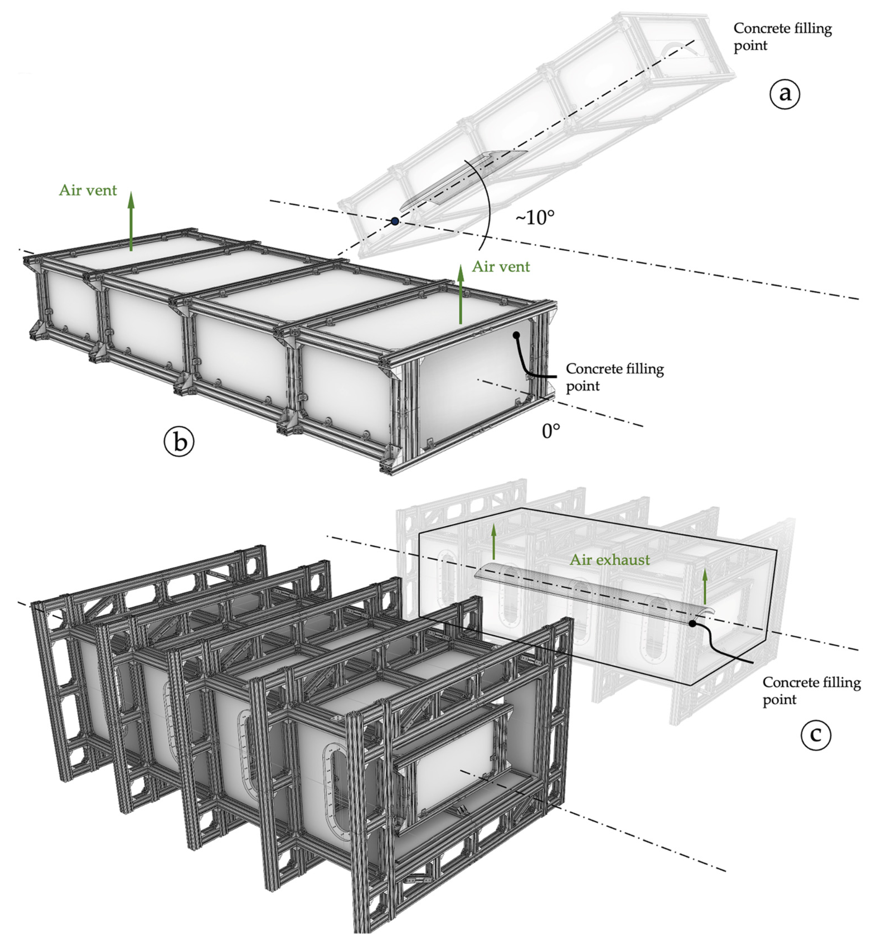
2.1. Working Principles

For the successful realization of the declared above production goals, a list of principles was compiled that needs to be followed during the development of the method. In Figure 2, all the principles are summarized in two groups. A so-called ‘Free-form Group’ collects the features that the method needs to possess to be able to provide ultimate freedom in the geometries production of the TRC structures. One of the most important aspects is an ambient shape control or, in other words, the possibility for the precise control of the shape from all sides to generate filigree TRC structures with high accuracy. As was indicated in the first stages of the current research project [14], the possible solution can be inspired by the production methods of composite structures made of polymeric resin and fibrous preform [15]. A similar approach but for TRC structures was indicated as a Resin Transfer Moulding (RTM) casting method [14]. Referencing the other industries and considering our performed development, the proposed method can be referred to as a ‘TRC die casting method’. Similarly to the traditional die casting method used for production using molten metal [16], the TRC elements are proposed to be casted into prepared die by a concrete pump that introduces hydraulic energy to the system. As part of the ambient shape control, consequent requirements are possibilities to ensure the production of thin-walled TRC structures with variable thicknesses and the respectful precise position of the textile reinforcement within the structures. A solution is described in Section 2.5.3.
The so-called ‘Worry-free Group’ collects the working principles required to guarantee high-quality casting by minimizing the possible defects in TRC elements. Because the other important demand regarding the proposed method is to realize the idea of invariance [17], according to this idea, the TRC elements are planned to be casted in the most ‘relaxed’ horizontal position to minimize the influence of hydrostatic pressure from fresh concrete onto formwork elements. Also, the same position during casting, regardless of the shape of the elements, promotes having clear roadmaps for all the participants and, as a result, the more efficient utilization and integration of the new technology [18] with the minimization of the possible scatter in the results that comes from the uncertainty of manual labour. Also, the invariance helps the proposed manufacturing method to match the key opportunities that are offered by Industry 4.0 by supporting a mass customization approach [19].
A possible mean source of defects in the casting of thin-walled elements, especially in an unfavourable position, is the presence of air inside the mould. Airlocks can completely block the concreting cavity and form ‘discontinues’, or accumulated air can result in macro voids or ‘defects’, especially on top of the concrete surface [20]. In addition, the entrapped air may experience high friction from densely packed reinforcement and form local air voids [14].

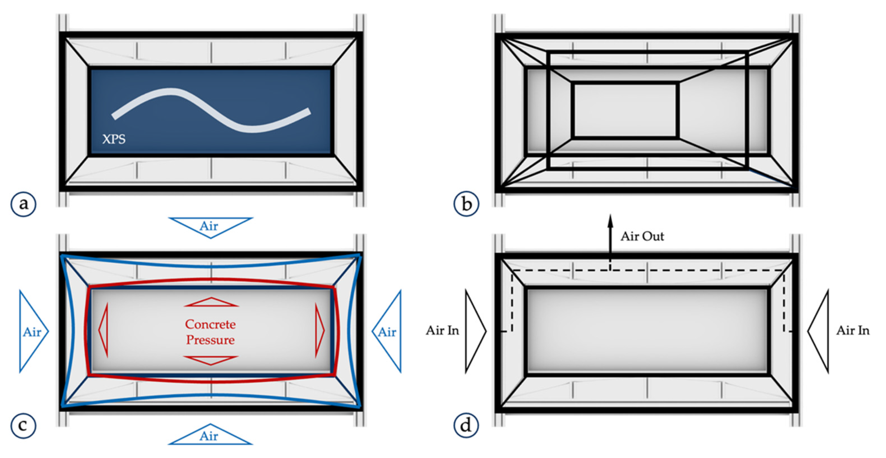
2.2. Vacuum Assistance

Referencing back to the standard die casting method for metal elements, the problem with air voids and reduced casting quality can be solved using various methods, but the one suitable for the production of the TRC structures is die casting with vacuum assistance. According to that idea, the vacuum assistance aimed to eliminate the dissolved gas in the matrix, reduce pressure in air locks and, through this, improve the casting quality, similarly to the metal vacuum-assisted die casting procedures [20,21,22]. Figure 3a–c shows the possible casting orientations of the TRC elements designed within the scope of the project. The red areas indicate the potential location of defects and discontinuities after the casting. As may be seen, any of the given orientations does not give a favourable solution for the casting procedure in the sense of trapped air. The mentioned vacuum assistance aimed to solve this problem and to realize the ‘invariance’ of the proposed method introduced above.
Referencing the initial research in the project, the ‘normal’ Air Pressure Conditions (APC) correspond to non-vacuum conditions. Negative pressure, and their respective vacuum conditions in turn, will be named as ‘negative’ APC. Additionally, it should be indicated that the utilization of negative APC promotes the reduction of the dissolved gas in the material matrix [14] and, as a result, porosity reduction. As is known, micro pores are in charge of crack initiation, therefore, within the scope of the project, an improvement in the material properties of high-performance concrete is possible, but is not an envisioned goal of the development.

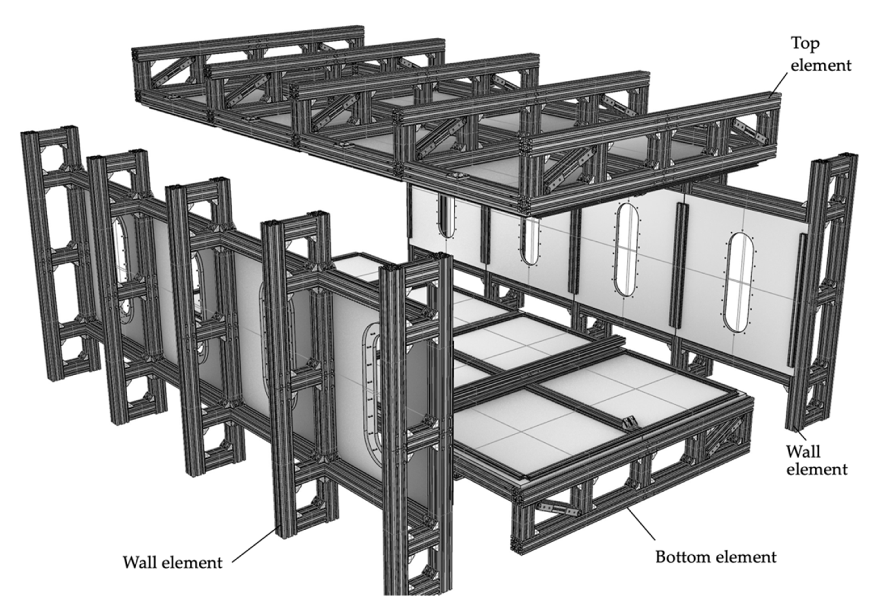
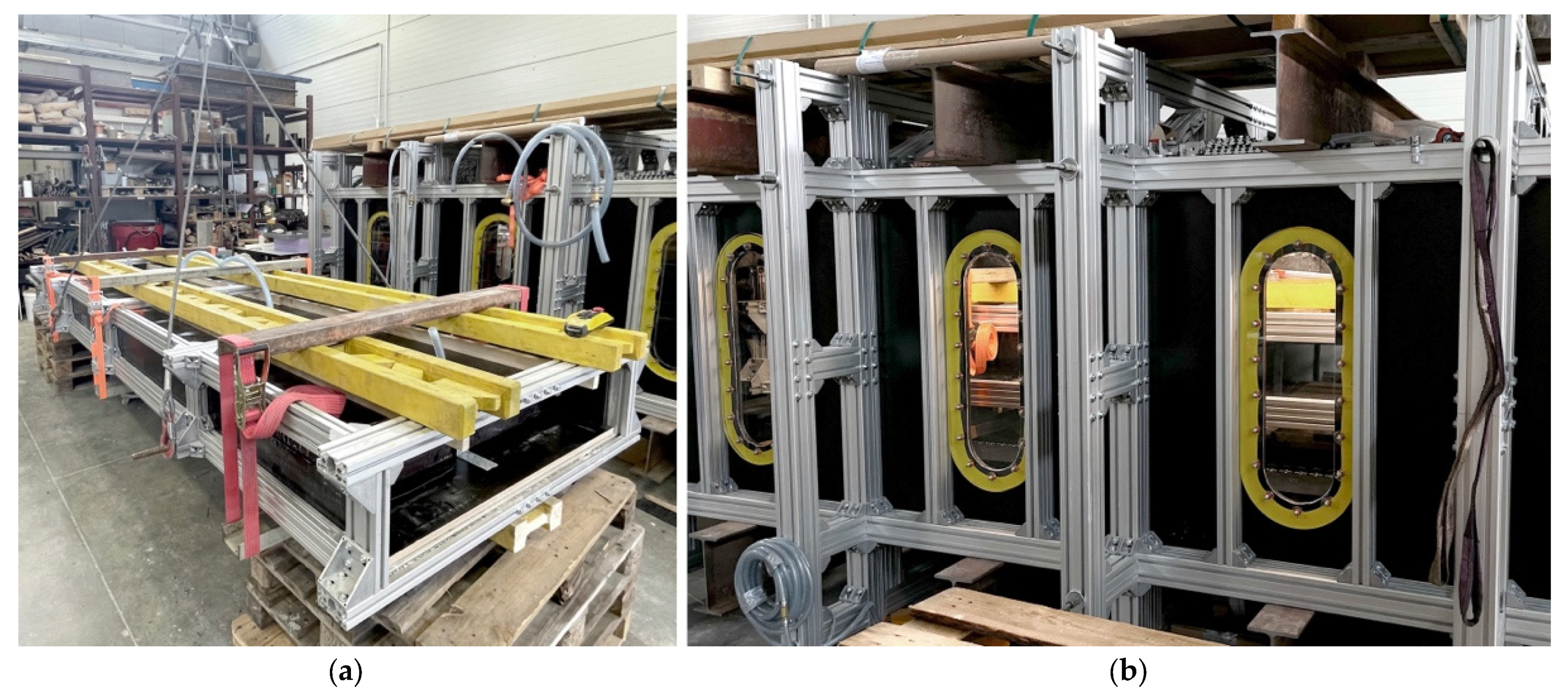
2.3. Construction of the Casting Chamber

To sum up all the aspects and requirements provided above regarding the concreting and vacuum chamber and their interaction, the next guidelines for the construction of the chambers may be highlighted. Figure 4 visualizes all of them. Thus, first of all according to Figure 4a, the system of chambers must be ready for the production of various TRC elements regardless of the geometry of the element. In this way it was decided that we would use Extruded Polystyrene (XPS) blocks as a material that may be easily cut to provide the required negative shape for casting but simultaneously to form a body to be installed into the concrete chamber. From Figure 4b, it follows that the vacuum chamber needs to be designed to adapt to the various shapes of the concrete chamber to be used for multiple work packages of the currently running project. Next, Figure 4c depicts that it is designed to ensure an air gap between the concrete and the vacuum chamber. Such a gap is required firstly to eliminate the influence of the deformation caused by external air pressure on the vacuum chamber. In the case of direct contact between the chambers, an inevitably deformed vacuum chamber will cause unrequired deviation inside the XPS blocks and, as a result, the required TRC elements’ geometry cannot be ensured. Furthermore, it was observed in the first technology tests and described in reference [14] that, right after the deactivation of the negative APC, the vacuum facility may experience a ‘reverse’ deformation that, in turn, considering the assumed thin-walled nature of the planned TRC elements, may significantly reduce the level of concrete within the casting mould. The reasons explained above for the necessary gap in-between the chambers were, in essence, the main driving argument to design the concreting facilities in the form of two independent chambers. Finally, Figure 4d gives another reason for the gap between these two chambers. It may be technically difficult to ensure a one hundred per cent sealed vacuum chamber and prevent any air leakage, and, therefore, the designed gap prevents the concrete chamber being saturated with air from the external walls. Thus, the concrete chamber remains in a stable reduced APC during the concreting procedure.
Figure 5 and Figure 6 show the concrete and vacuum chambers, respectively, in more detail. It may be seen from Figure 5 that the cage of the concrete chamber is assembled from a set of aluminium profiles and plywood panels. The cage contains the set of XPS blocks that works as a mould for the concrete die casting procedure and ensures the correct shape of the final TRC element from all directions. As is indicated in Figure 5, the XPS blocks have a special profile. Some part of the profile serves as formwork. The other part forms a special leakage lock. A sufficient closure between the XPS blocks prevents concrete leakage during the casting and ensures the easy separation of the blocks afterwards. The maximum size of the XPS set that can be installed is 3600 × 1200 × 500 mm. In the case of small TRC samples to be casted, additional general and reusable XPS blocks can be used to fill an empty space and ensure pressure in-between the shape blocks.
Figure 6 introduces the constituent parts of the big 4100 × 2760 × 1820 mm vacuum chamber. It was constructed from four main components assembled from a sequence of aluminium frames designed to keep the significant atmospheric pressure. The chamber is equipped with two openings located at its longitudinal ends to provide access for a maximum 3800 × 1800 × 600 mm measuring concrete chamber to be installed inside. For the convenient installation of various concrete chambers, the big vacuum chamber was equipped with a special rolling system. In this way, the installation process takes, on average, less than 15 min.
For the concreting of the specimen for standard tests, a small vacuum chamber was built according to the principles described before. For the sake of completeness, the very first constructed facility for concreting under a vacuum shall also be mentioned. Both are shown in Section 2.5.2.

2.4. Test Program and Materials

To verify the working principle of the new casting method, different specimens were manufactured under normal and negative APC. As so-called standard material characteristics, we determined the bending tensile and the uniaxial compressive strength on plain concrete prisms, and the uniaxial tensile strength as well as bond characteristics for the composite TRC. Within the frame of the proof of concept, we also conducted selected tests on cylindrical specimens to determine the elastic modulus and the σ-ε relation of the plain concrete. Furthermore, 2.7 m long shell elements were produced under normal air pressure at first in an inclined position. To reduce the work effort and fresh concrete pressure, we concreted afterwards two shell elements in a horizontal position, one under normal and one under negative APC. The test program is summarized in Table 1 and sorted chronologically according to the date of concreting (the denomination of the test series is explained in the table caption (c)). In the current paper, the percent values of 60% and 80% in the case of negative APC means, respectively, ambient air pressures of 400 mbar and 200 mbar.
In the project, we use a fine-grained concrete mixture well suited for combination with textile grids made of carbon fibres. The mixture ‘C3-B2-HF-2-190-2’ was developed in the frame of the joint research project C3—Carbon Concrete Composite, basic project C3-B2, by the Institute for Building Materials of TU Dresden and the Deuna cement plant (Dyckerhoff® company, Wiesbaden, Germany) [23,24]. The composition is given in Table 2.
The epoxy resin impregnated, symmetrical, bidirectional mat solidian GRID Q85-CCE-21-E5 [26] was selected as reinforcement. The factory-guaranteed properties are provided in Table 3.

2.5. Manufacturing of Specimens

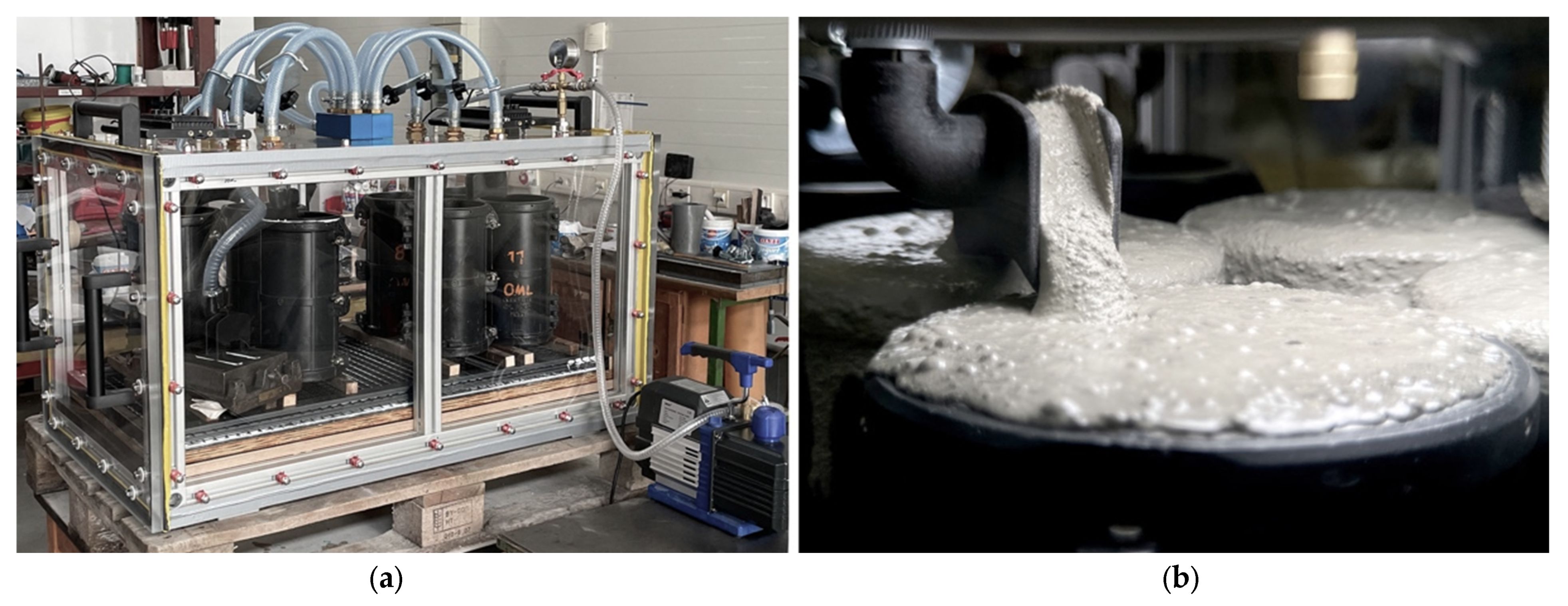
2.5.1. Samples for Standard Tests—Normal Conditions

Concrete prisms with dimensions of 40 × 40 × 160 mm are used to determine the bending tensile and the uniaxial compressive strength according to DIN EN 196-1 [27]. The prisms were casted in steel formworks and firstly remained in the moulds, covered with wet cloths. After demoulding on the 2nd day, they were stored in water until the 7th day and afterwards at 20 °C in a climate chamber with 65% relative humidity until testing at an age of 28 to 31 days. The cylindric specimen, with 150 mm diameter and 300 mm height, of series AP2_ST_02 was also left for one day in the mould, covered with wet cloths until the 7th day, and under lab conditions until the day of testing. They were used to exemplarily determine the elastic modulus and the stress–strain behaviour of the C3-B2-HF-2-190-2 concrete under uniaxial compression.
For uniaxial tensile tests on TRC specimens, as fundamentally described in reference [28], test samples are cut from a larger plate. Usually, in our lab, we concrete a 1220 mm × 540 mm measuring plate (per batch), from which samples for tensile and bond tests can be extracted. The plate thickness and the amount of carbon reinforcement layers can be varied, e.g., depending on the planned application, the maximum grain diameter and the layout of the reinforcement. For the first comparative tests between concreting under normal and under negative APC (series AP1_Ph1), we chose a plate thickness of 40 mm and a two-layer reinforcement according to the later planned shell elements. For series AP1_Ph2_1.3, we concreted thinner samples with a thickness of 25 mm. The reason for this was the general proof of concept, especially regarding the achievable quality while concreting under negative APC and preparing the material data for the calibration of the numerical analysis for further phases of the project development. After concreting, the whole slab was stored for one day under wet cloths, then until the seventh day under water and, afterwards, at 20 °C in a climate chamber with 65% relative humidity until testing.
To determine the bond characteristics between the carbon fibre textile and cementitious matrix, we used the single-sided pull-out test (SPO), e.g., see reference [29]. The test set-up is well suitable for a basic material screening, e.g., for comparison purposes when studying different matrices, textiles or just manufacturing conditions. The principal production of the samples corresponds to that of the tensile test samples. However, SPO specimens contain only one textile layer, with thickness of sample which was set to 10 mm. The SPO samples are symmetrical notched from both sides before testing. Thus, only the centrally situated yarn is pulled out. This yarn, in turn, is drilled or sawed through at a defined distance from the notches to fix the available anchorage length. The result of this kind of test is the force that can be transmitted at this special anchorage length.

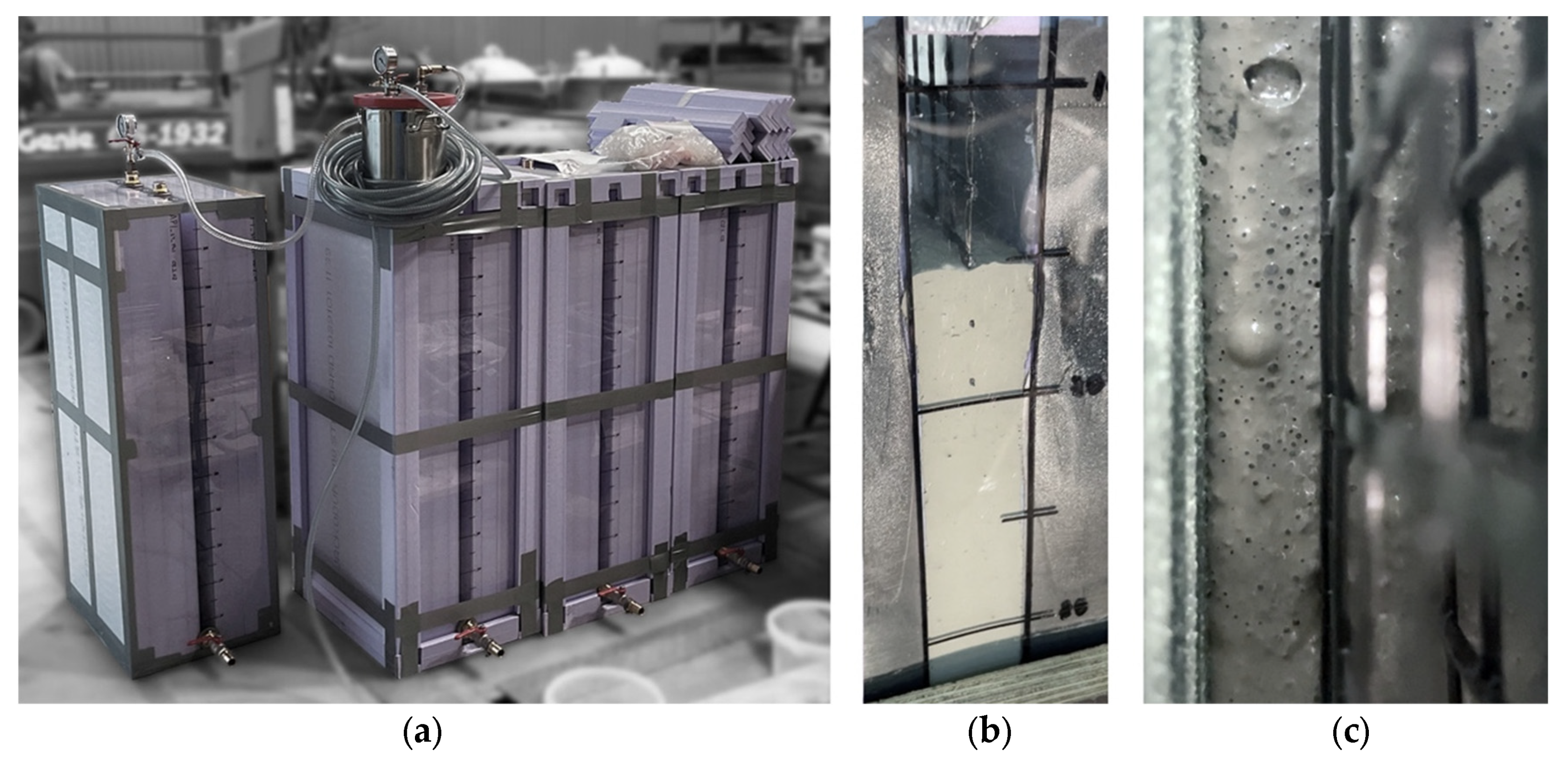
2.5.2. Samples for Standard Tests—Negative APC

Figure 7a shows the small vacuum chamber used to concrete the samples for the standard tests under negative APC. The chamber was designed to pack a large number of standard moulds. In the example shown, seven cylinders, three prisms and one 970 mm × 380 mm measuring plate for later cutting into five tensile test samples or five SPO test samples were casted simultaneously over a short period of time to ensure similar properties for concrete and ambient conditions. The formworks were filled stepwise one after another via the pipe system that was controllable due to the clamping devices that can be seen in Figure 7a on top of the facility. After the concreting, the fresh concrete samples remained for another 30 min under negative APC. During the concreting, an active deaeration was observed on the exposed fresh concrete surface, see Figure 7b. After this 30 min post concreting time period, the deaeration was almost finished due to the formation of a stiff enough film on top of the fresh concrete surface.
Subsequently, the chamber was opened. The next day, formworks were opened and the samples were stored in the same manner as the normal APC specimens. Until testing, they were then kept in the climatic chamber like the other specimens.
For the sake of completeness, the very first constructed facility for concreting under a vacuum shall also be mentioned (Figure 8), [14]. This prototype was used to concrete the tensile specimen of series AP1_Ph1. In contrast to the small vacuum chamber, the samples were concreted vertically, covered by XPS all around, except the narrow long sides. Here, transparent polymethyl methacrylate (PMMA) sheets allowed for observing the filling process.

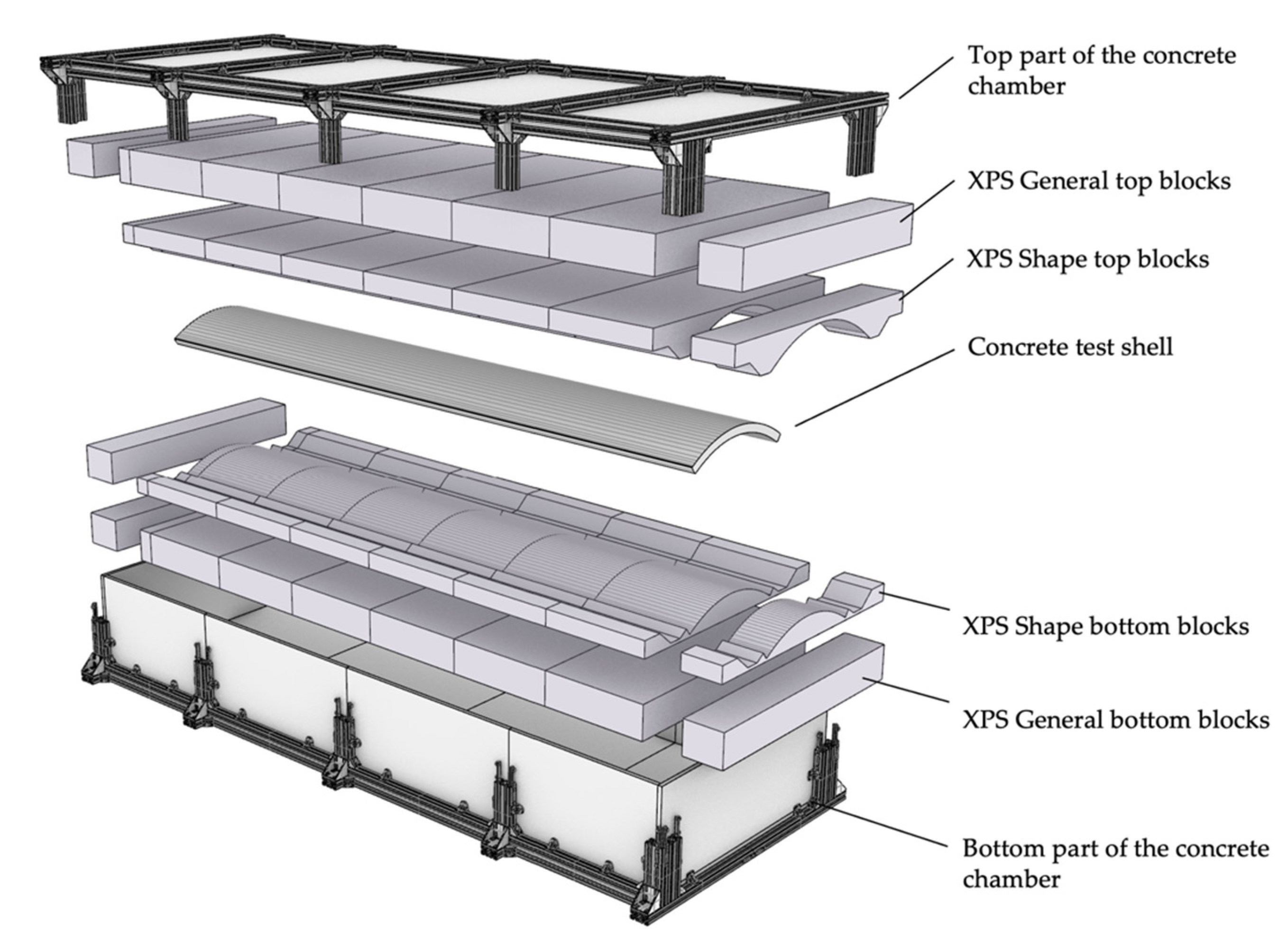
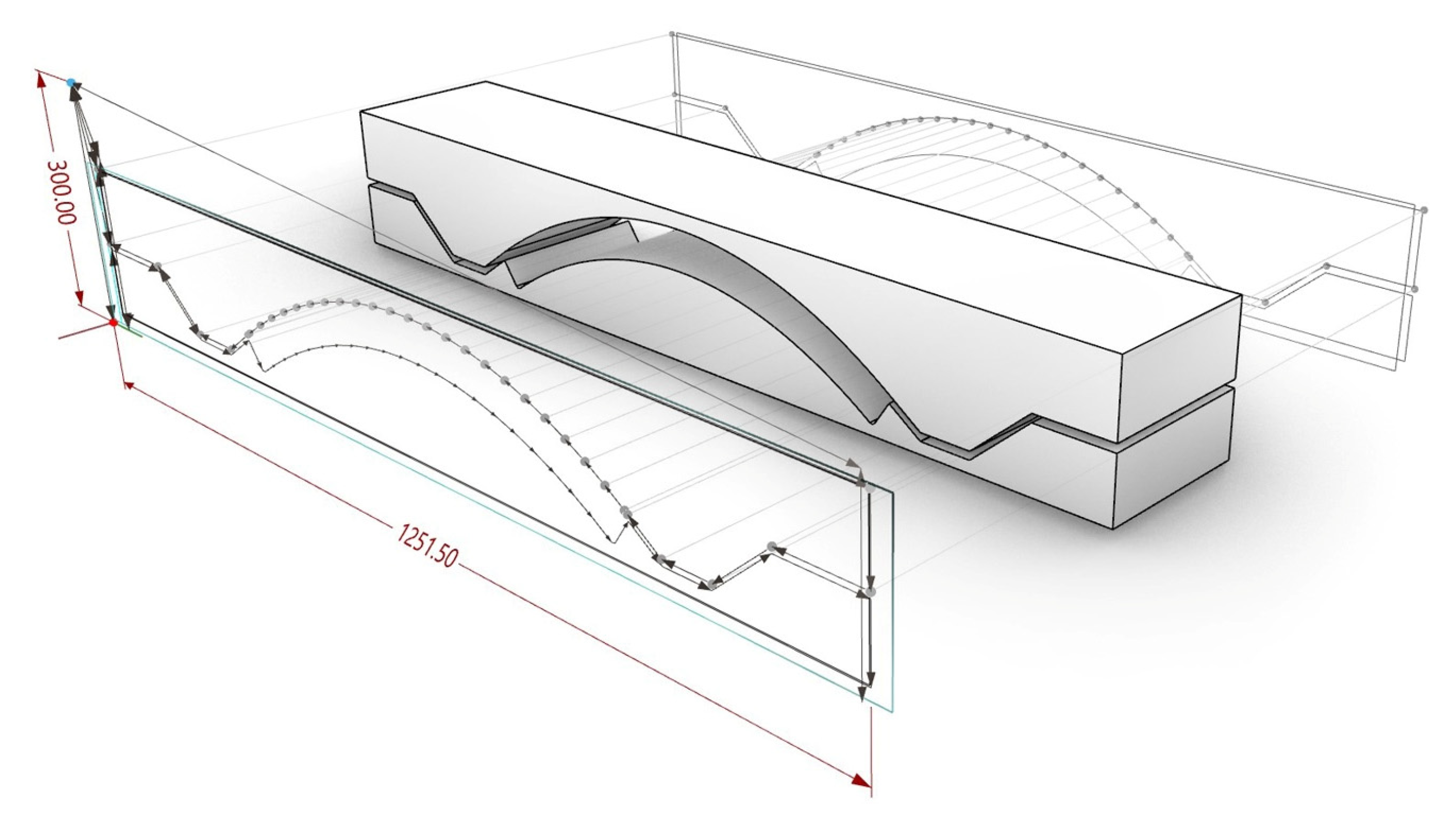
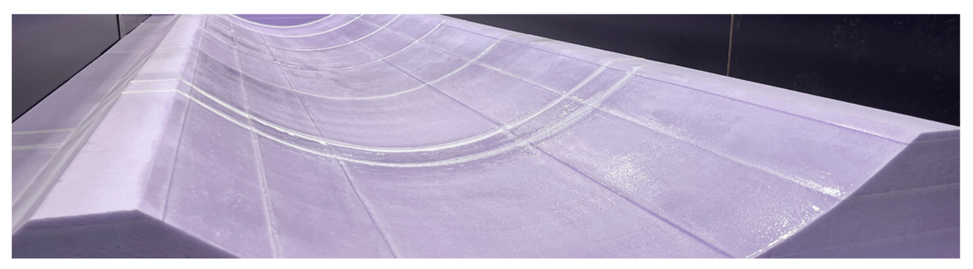
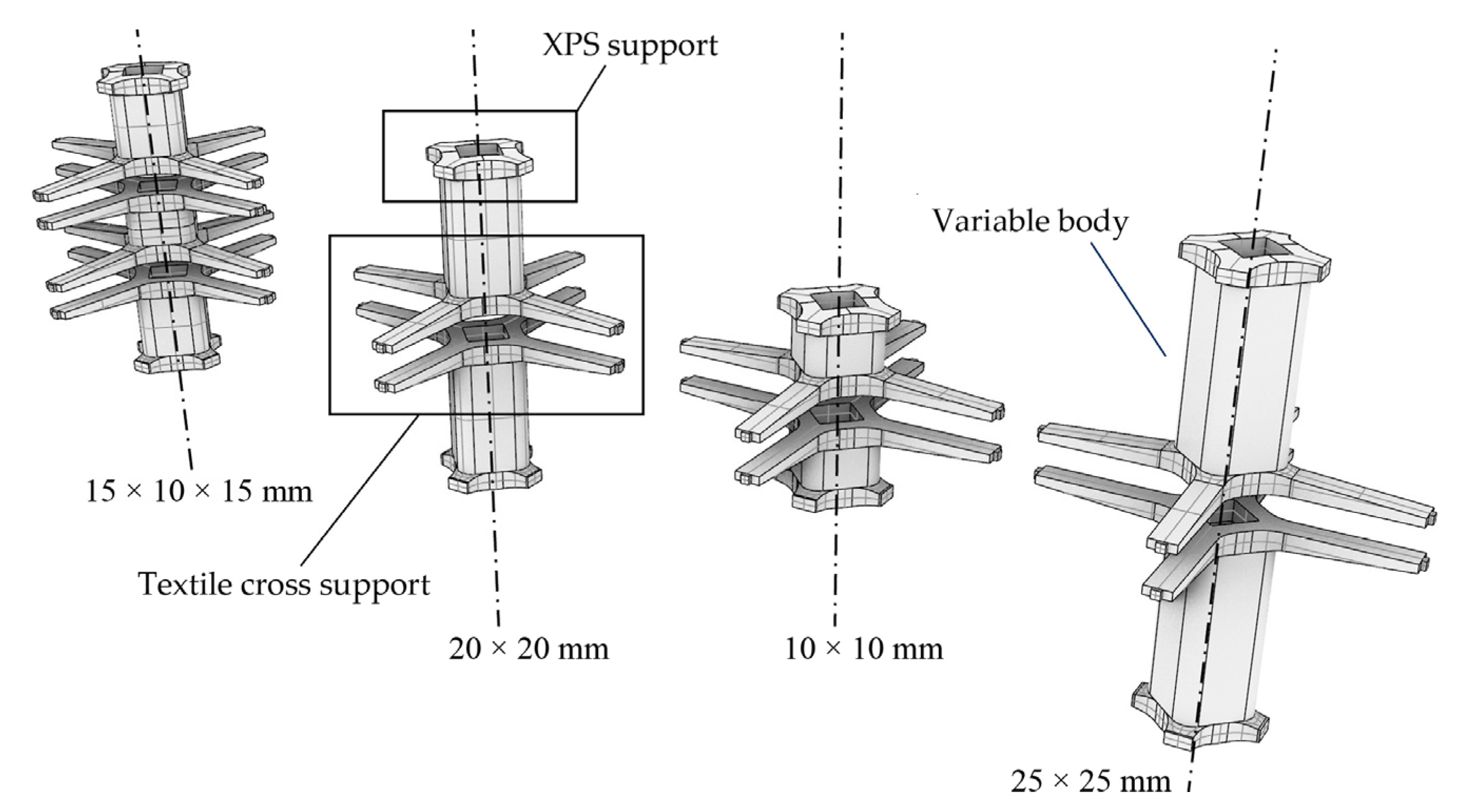
2.5.3. Preparation of Formwork and Other Components for the Shell Elements

Based on the successful experience of the realization of the carbon-reinforced concrete building CUBE [9,10], it was decided that we would use XPS cut blocks as removable formwork for the production of the TRC shell elements. XPS possesses properties that make it a perfect material for the formwork preparation. It is soft enough to be rapidly cut using a CNC machine equipped with a hot wire cutting tool and simultaneously give enough stiffness to withstand the hydrostatic pressure of the fresh casted concrete. In order to reduce the proceeding time for the formwork preparation, one of the tasks was to develop a production routine that ensures the usage of the cut XPS blocks multiple times. Figure 9 shows a Rh + GH environment aimed at preparing a G-Code for the cutting of the XPS blocks, which was then performed using a CNC cutting machine with four independent axes. The cutting hot wire was calibrated to keep 1.5 mm offset from the ‘perfect’ required surface of the XPS blocks. The distance was derived after a set of preliminary tests and selected as a balanced position to keep the average cutting temperature appropriate for the cutting of the segmented blocks.
Besides the benefits of XPS usage, there is also a drawback that needs to be considered. For instance, the cutting procedure emits a noticeable amount of fumes, so additional ventilation is required. The XPS blocks left a significant amount of waste after the concrete casting that, in turn, need to be disposed of. Regarding the CO2 footprint, the XPS material can be considered as a negative emission material because it can be used for energy generation [30]. But, of course, there is a vast need for circular solutions without downcycling for the building of the future.
The separate XPS formwork blocks after the cut procedure were first glued together and grinded to eliminate the sharp edges that were left after the cutting procedure due to the uneven redistribution of the temperature along the hot wire. Figure 10 shows the connected and smoothed formwork for the production of the TRC shell from Figure 5.
To be used multiple times, the XPS blocks needed to be prepared for easy separation from the concrete elements after initial curing. Thus, it should be covered with an appropriate release agent. For the project, we decided to use a Ecoratio Betonpro release agent [31]. Another option was the application of the two-component epoxy resin from brand Toolcraft® (Fort Wayne, IN, USA) in combination with a layer of oil. The epoxy resin was applied in five layers to prevent its accumulation in the lower regions of the formwork. Figure 11 shows four cases with different amounts of applied agent that were compared to find out the best combination of the release agent and XPS formwork.
From the figure, it may be seen that the amount of the Ecoratio release agent has a significant influence on the quality of the surface at comparable separability. Furthermore, the amount of release agent with approximately 270 g/m2 results in a noticeable quantity of oil on top of the concrete surface. Epoxy gives a smooth surface without a pattern in contrast to the surfaces received using the Ecoratio release agent.
After the concreting tests, however, it was found that both solutions possess significant drawbacks. The Ecoratio release agent promotes significant melting (approx. 5 mm depth) of the XPS blocks, which was visible after the demoulding. Such XPS blocks cannot be used again for the next concreting. Epoxy resin in combination with oil resulted in insufficient separation from the concrete surface. Thus, for the successful realisation of the project it was decided to combine both methods. The epoxy resin was applied first to cover the XPS blocks’ surface with a protective film. Afterwards, the Ecoratio release agent was applied on top of the epoxy resin surface. This combination ensures an appropriate level of separation from the TRC surfaces. Finally, the Ecoratio release agent and its viscous nature is an important part of the leakage lock in the XPS blocks provided above.
The other important aspect that ensures flexibility in the production of filigree TRC elements is the specially prepared space holders for the textile reinforcement designed according to the principle of mass customization. Figure 12 shows the general view and constituent parts of the developed space holders.
The modular designed space holders ensure the fixation of the textile reinforcement grid at the ‘Textile cross supports’ and appropriate contact with the XPS formwork blocks via the ‘XPS support heads’. The separately printed ‘Variable body’ allows for exactly defining the thickness of the TRC member. To finish the installation, laboratory technicians need to assemble all the parts into a merged single space holder. The provided space holder solution fulfils the main features of the die casting TRC manufacturing method. Besides ensuring the correct position of the textile reinforcement regardless of the member’s thickness, they provide the option to install different combinations and numbers of layers of textile reinforcement. Figure 12, for instance, shows a solution with a spacing of 15 × 10 × 15 mm for two textile layers (left) and another one for a single textile layer for spacing from 25 × 25 mm to 10 × 10 mm (right).

2.5.4. Concreting of the Shells

To perform clear comparable research into the influence of the die casting TRC production method and related techniques onto the quality of the final TRC shells, a sequence of cases in the modification of the concreting setup were performed (see also Table 1). Two parameters were selected to be varied: first, the angle of inclination of the concrete chamber and, secondly, the ambient air pressure conditions:
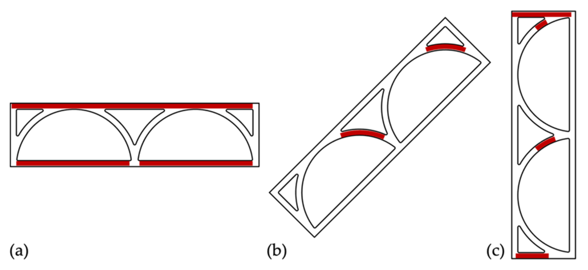
  • Inclined position of the concrete chamber with circa 10° in normal APC;
  • Horizontal position of the concrete chamber in normal APC;
  • Horizontal concrete chamber assisted with negative APC.
All the cases are visualized in Figure 13. The first case from Figure 13a is considered to serve as a reference point that assumes a basic die casting method without the assistance of the negative APC. The chamber was inclined for deaeration with an angle of near 10°. The concrete was filled in from the top right side of the chamber. Due to the inclination, the hydrostatic pressure at the bottom of the chamber was equal to 9.2 kPa. Therefore, the concrete chamber was assembled with additional longitudinal I-beams to provide sufficient stiffness. Also, the beams served as a measure that helps to introduce additional compressive stress to the inner XPS formwork blocks in order to prevent concrete from leaking through the gaps.
The second case in Figure 13b was aimed at eliminating the inclination of the formwork that was indicated at the beginning of the paper as a not-desired position for the concreting of complex elements. Now, the concrete was casted through the special ducts in the middle point of the concrete chamber to provide an equal possibility for the fresh concrete to reach the farthest points of the formwork. The chamber was additionally equipped with air vents to control the level of concrete during casting and to detect the point when concreting should be stopped. The air vents were also designed to be used as channels for air exhaust and, in that way, balance the air pressure outside and inside the concrete chamber.
The third case of the die casting procedure was the introduction of the negative APC assistance. As shown in Figure 13c, the concrete chamber was installed inside the vacuum chamber. The concrete was thus pumped through the door of the vacuum chamber directly to the concreting duct, analogous to the second case. The length of the concrete supplying pipes between the inlet in the vacuum chamber and concrete chamber was kept as short as possible to reduce the concrete friction inside the pipe system. Even though it reached up to 2–3 atm at the outlet of the concrete pump, such behaviour supports the hypothesis of concreting difficulties for complex TRC structures referenced in reference [14]. In contrast to the first case, the horizontal concreting resulted in less hydrostatic pressure that equals 2.3 kPa. The negative APC applied during the third case of concreting was kept at the level of 60%. This was technically the maximum achievable level of the vacuum for the big chamber at that time. The concreting procedure of the TRC shell itself took nearly 30 min. The pumping velocity was adjusted to keep the pressure in the pipes within the medium values of 4 atm, considering that the pipe system was designed for a pressure up to 8 atm.
Figure 14a gives an insight into the concrete chamber appearance, including the additional I-beams for stabilization, prepared to be installed inside the vacuum chamber. Figure 14b shows the big vacuum chamber during concreting. It was designed to provide enough observance of the process going inside the chamber and to control the level of the pumped concrete and condition of the supplying pipe system.
After the concreting was completed, the negative APC remained active for another 30 min, analogous to the standard specimen production described before (Section 2.5.2). Thus, the total duration of the negative APC assistance was equal to nearly 60 min. After opening the vacuum chamber, all the concreting pipe system was removed.
For all three cases, the demoulding procedure looked similar. During the first four days of curing, the concrete chambers were stored in the same position either inclined or horizontal as they were during the concreting procedure. Then, the concrete chamber was opened and the XPS blocks were separated from the concrete surfaces with the consequent repair of the local damages caused during the demoulding or concrete casting. Until testing, the shell elements were stored under room conditions (at circa 20 °C and 60% relative humidity) in the concreting hall of the lab.
Finally, it should be pointed out that all the small-scale and large-scale test samples were concreted using the same concrete pump. This selection should be mentioned for the reason that the properties of the concrete matrix may be influenced while going through the moving parts of the concrete pump. A deviation concerning this matter should be excluded.

3. Test Conduction and Experimental Results

3.1. Small-Scale Tests on Plain Concrete

3.1.1. Bending Tensile and Compressive Strength on Prisms

Prisms were at first tested under three-point bending according to DIN EN 196-1 [27]. Afterwards, the remaining broken pieces were used to determine the compressive strength. In Table 4, the test results are summarized.

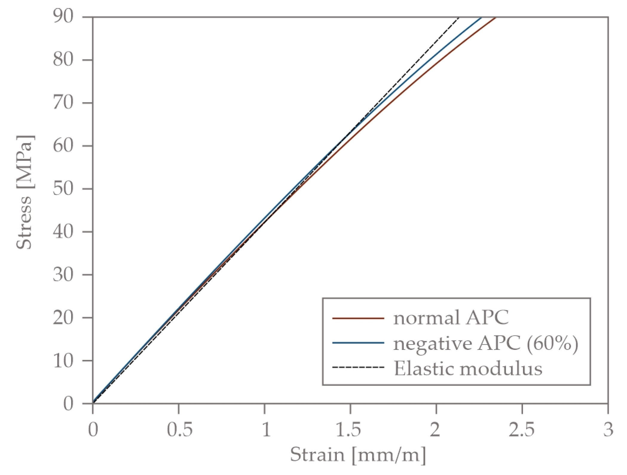
3.1.2. Compression Tests on Cylinders

Six cylinders were tested according to DIN EN 12390-13 [32]. Three were concreted under normal and three under negative APC. The test procedure included, firstly, loading twice to a stress level of 1/3 of the estimated failure load; after holding this load level for 1 min during the third loading sequence, the load was increased until failure. The results are summarized in Table 5 (second and third columns).
On another five samples, we determined the stress–strain relation of the plain concrete under compression and continuous loading. Three of the five samples were concreted under normal and two under negative APC. The strains were recorded with two strain gauges glued on opposite sides of the surface of the cylinders. The strength values can be seen in Table 5 (fourth and fifth column). The mean stress–strain relations are displayed in Figure 15 until a load level of 90 MPa. For comparison purposes, the elastic modulus specified in Table 5 was calculated in a stress region between 18 and 40 MPa.

3.2. Small-Scale Tests on TRC

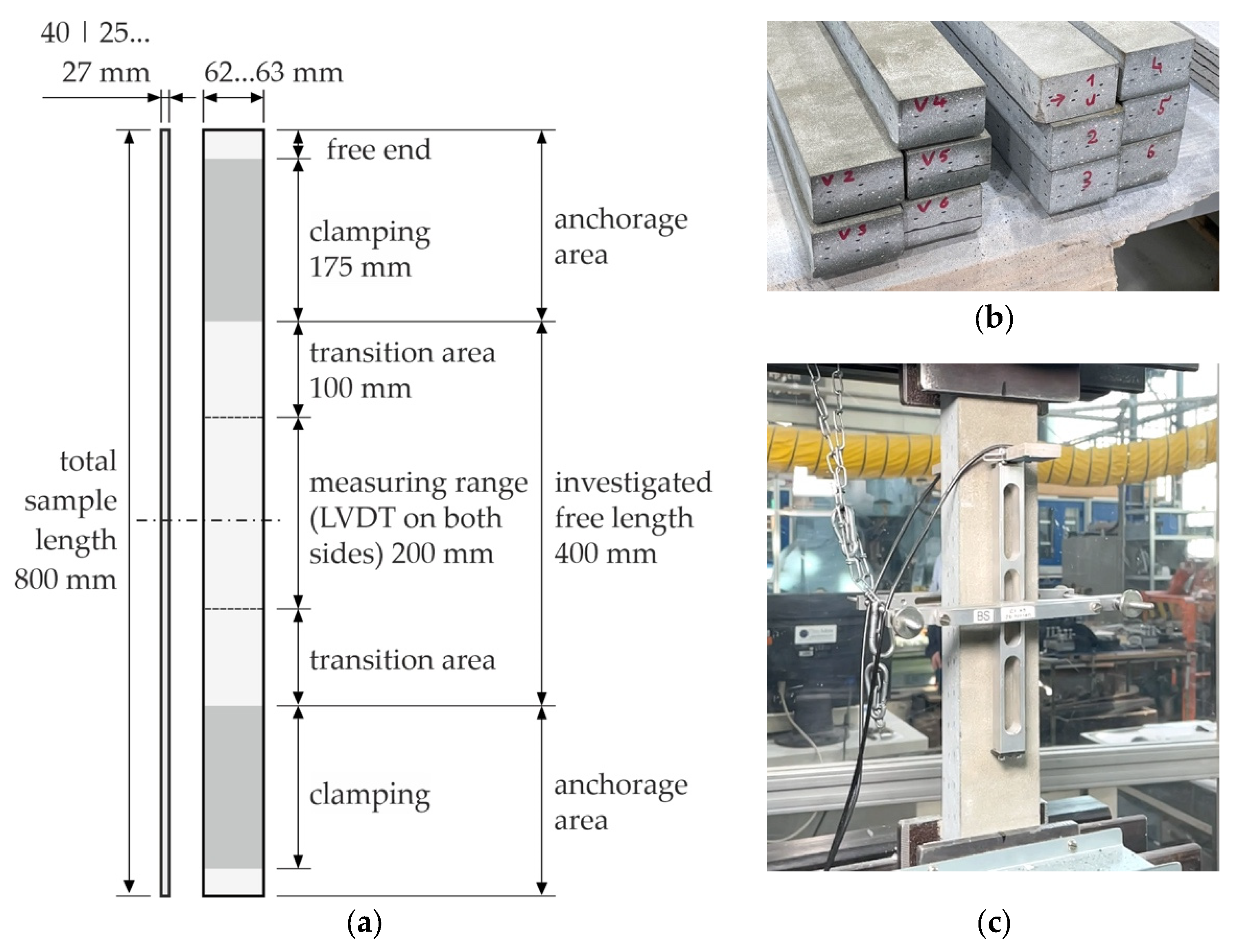
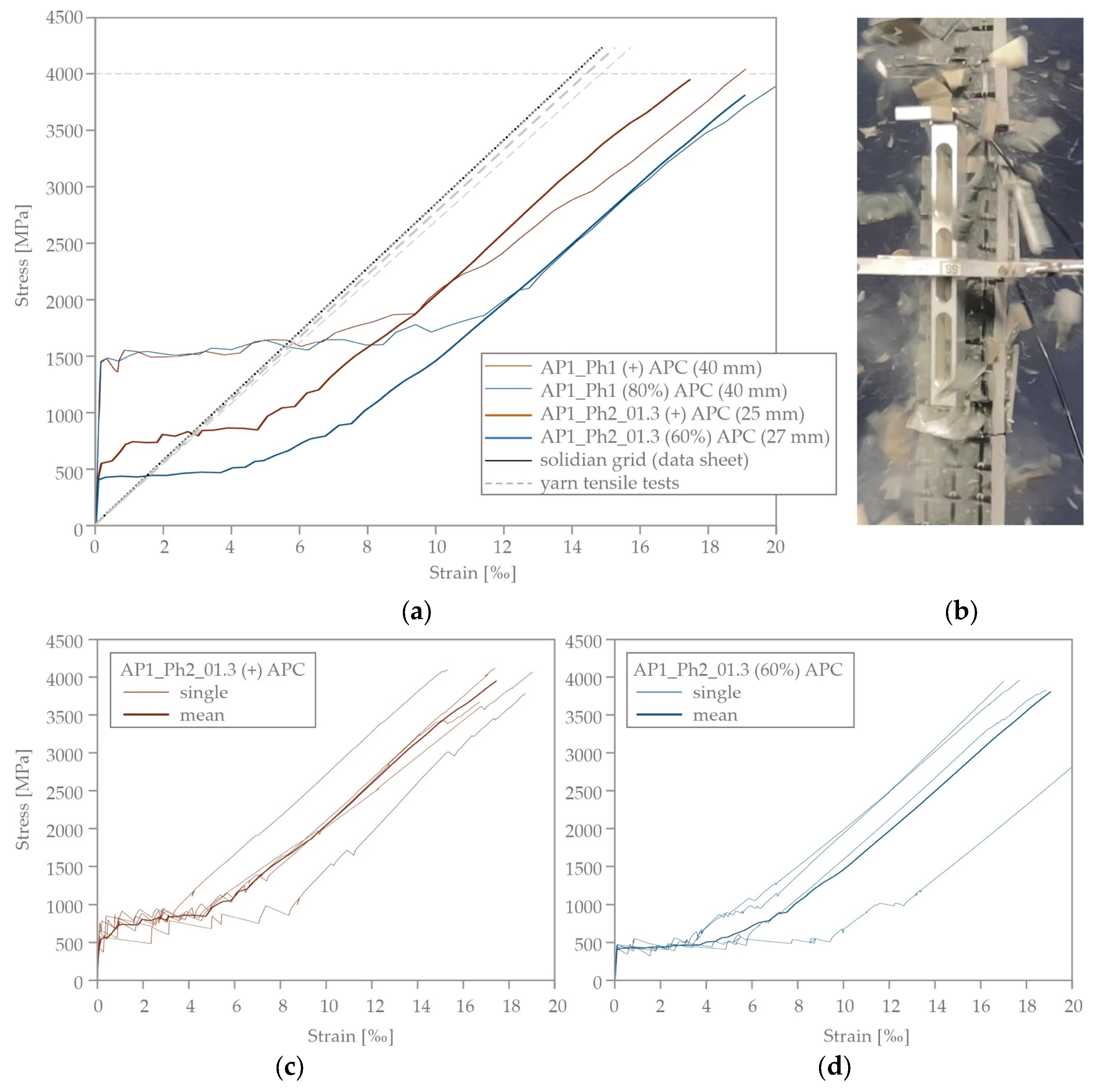
3.2.1. Tensile Strength of TRC

The principal dimensions and the test set-up for the tensile tests on TRC samples are shown in Figure 16.
The reinforcement was located centrically with a distance of 10 mm. The concrete covers on both sides of the test samples were equal to 15 mm (series AP1_Ph1) and 7 to 8 mm (series AP1_Ph2_01.3), respectively. Per layer, three rovings were tensioned (see Figure 16b). In general, the free length of the specimen is 400 mm. Due to technical circumstances, it was 300 mm for series AP1_Ph1 (Figure 16c), but, from our experience, this does not influence the test results. The samples were loaded with displacement controlled with a loading speed of 0.03 mm/min until failure. In addition to the force, the deformation was recorded with two LVDTs with a measuring range of 200 mm.
The determined mean stress–strain relations are shown in Figure 17a. The diagrams in Figure 17c,d show the scatter within the series AP1_Ph2_01.3. The shape of the curves displays the typical behaviour of TRC under tension. A first steep increase (state I) ends due to the formation of a first crack, followed by nearly horizontal curve progressions (state IIa). The visible sharp leaps result from successive further cracking. After the completion of crack formation, the curves increase continuously until failure (state IIb) due to the rupture of the carbon textile grid. In all trials, we observed the spalling of the concrete cover which is typical for the used concrete in the region of high stresses, see Figure 17b. It was remarkable that both cracking and splitting were accompanied by significantly more noise development in the vacuum-concreted samples than in the normal concretes’ ones.
All curves concur regarding the failure strength and the increase in state IIb, parallel to the stress–strain behavior of the pure grid or single yarns (curves are added in Figure 17a). There are some deviations in the amount of horizontal shift and the load levels of the first crack and of the state IIa region. From the results shown here in the frame of the intended proof of concept, we cannot specify the exact reasons. The possible reasons are charge dependencies or the different sample thicknesses, as well as the concreting parameters (e.g., vertical or horizontal position during concreting). A sliding of the LVDT also cannot be completely excluded.
Figure 18 shows two sets of damaged TRC samples—Figure 18a, the samples manufactured under normal APC, and Figure 18b, the samples casted under negative APC. During the test realization it was noticed for both sets under normal and negative APC that the deformation of the samples was accompanied by significant strain energy accumulation and the consequent explosive manner of the failure event. After the collapse, the test samples showed a significant splitting of the concrete matrix and the tensile rupture of the textile reinforcement.
The difference between the two sets was noticed in the average number of cracks that appeared during the tensile load application. Thus, according to the test data, an average amount of 3.4 and 5.2 cracks was determined within the measuring range of 200 mm in the samples manufactured under normal APC and negative APC, respectively. This can be seen also from the figure. Figure 18a shows many long concrete matrix fragments stuck in between the two layers of the textile with transversal cracks at a distance of up to four textile reinforcement yarns in the weft direction. The other Figure 18b shows a transversal crack in the concrete matrix almost at every weft textile yarn. Such behavior may indicate an increased bond between the concrete matrix and the textile reinforcement in the samples manufactured under negative APC.

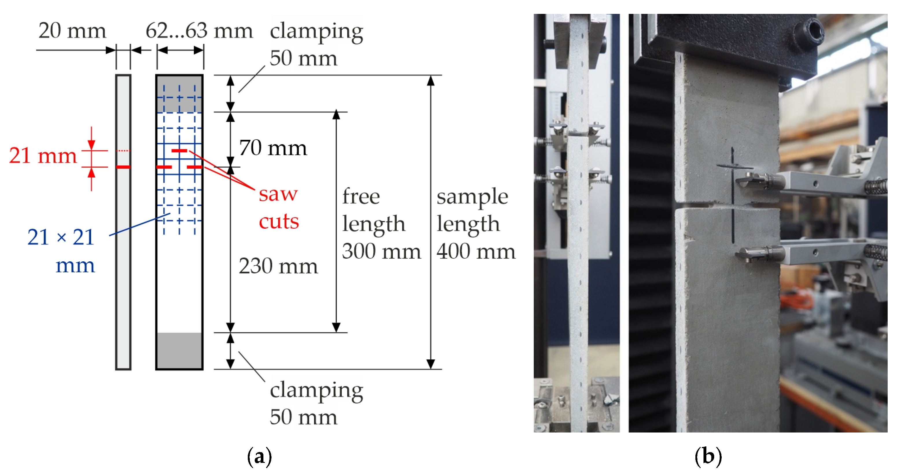
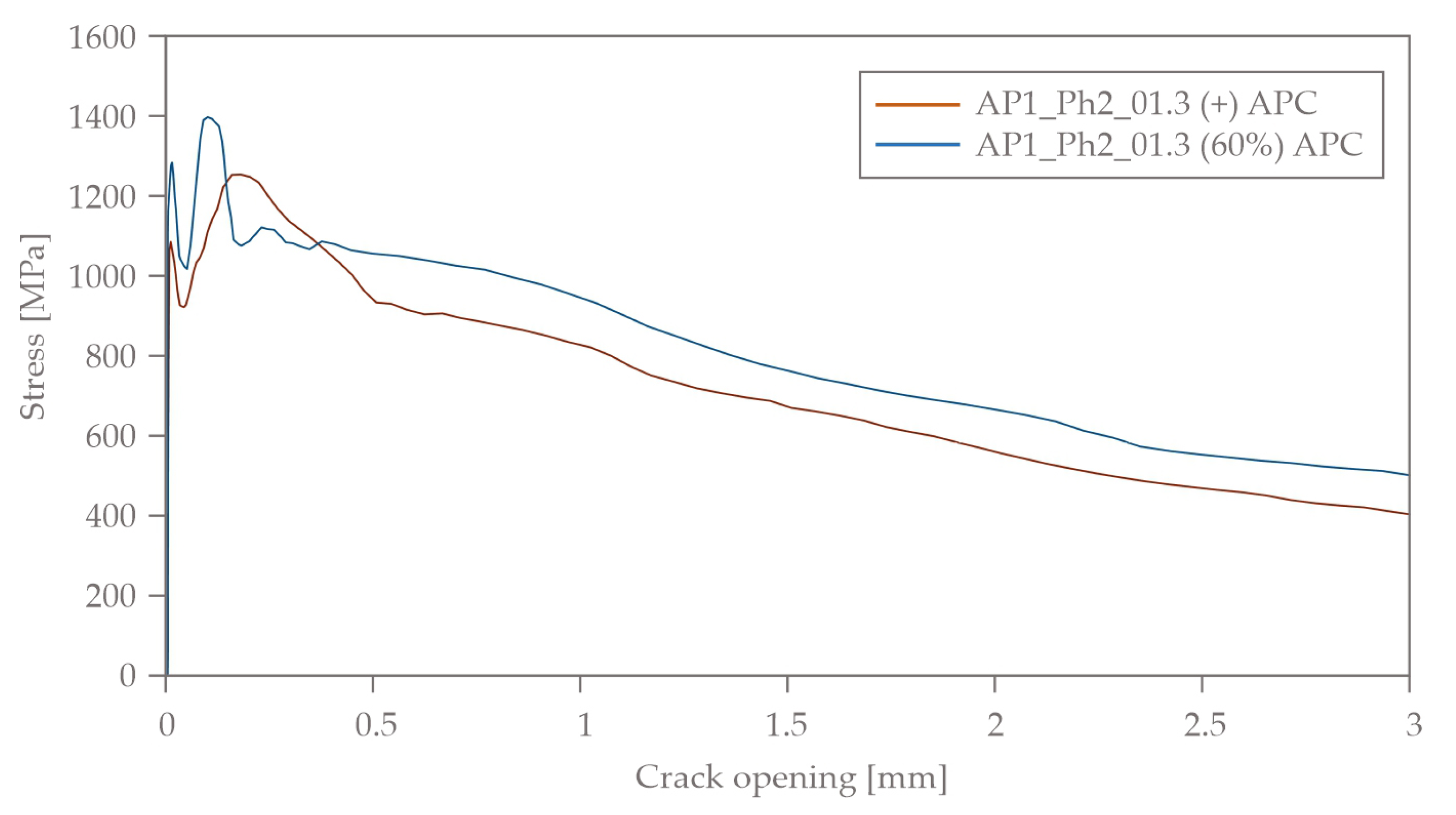
3.2.2. Bond Characteristics

The principal dimensions and the test set-up for the single-sided pull-out (SPO) tests on the TRC samples are shown in Figure 19. The lateral saw cuts were made exactly between two yarns. The middle continuous yarn was cut with an offset of one mesh width. In addition to the force, the crack opening in the predetermined breaking region was measured using an extensometer. The samples were loaded and displacement controlled with a loading speed of 0.03 mm/min until failure.
The mean bond stress–slip relations, calculated from the recorded forces and displacements, are shown in Figure 20. The curve AP1_Ph2_01.3 (+) APC was determined from five, and that for AP1_Ph2_01.3 (60%) APC from four single tests. The general shape of the curves is similar. On average, for the samples casted under negative APC, the adhesive bond was exceeded at a higher load level compared to the samples produced under standard conditions. All samples failed due to the pulling out of the middle yarn. A spalling of the concrete cover was observed for all samples casted under negative APC and for three of the five samples casted under normal APC.

3.3. Shell Tests

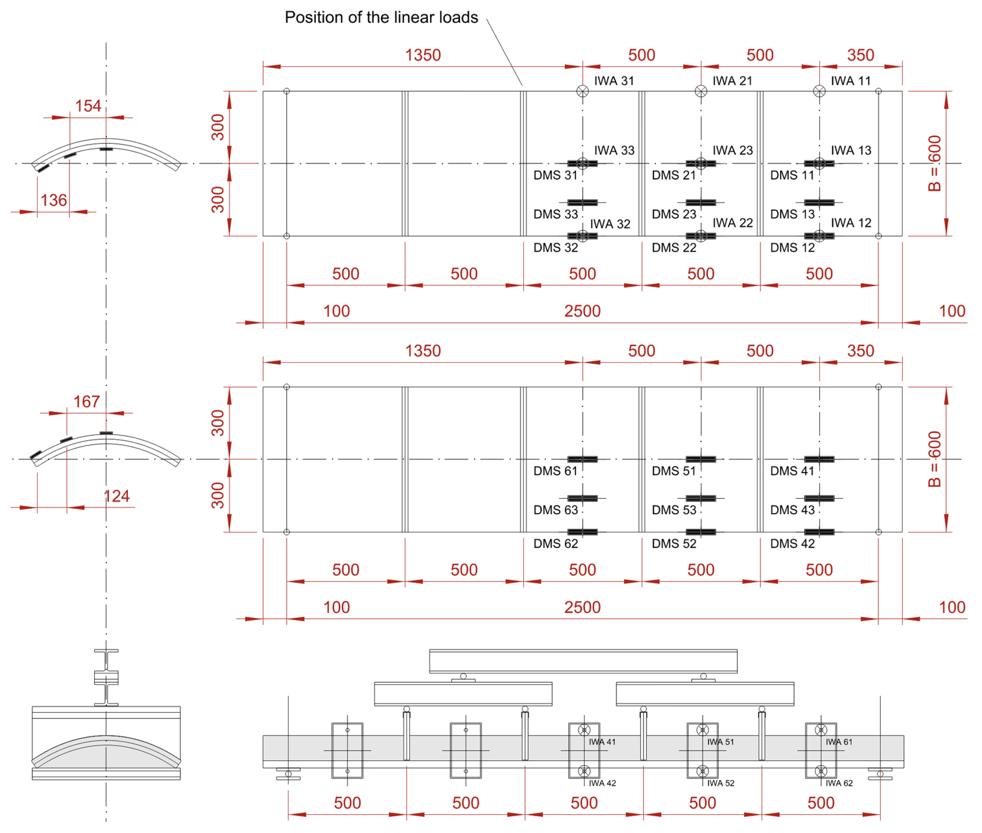
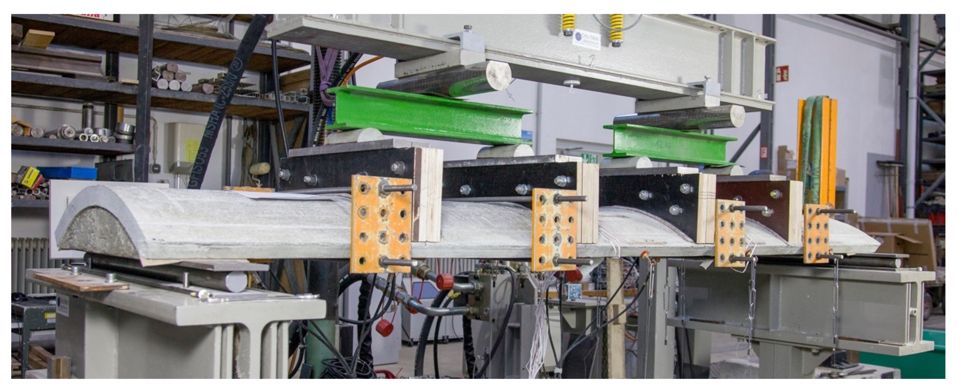
3.3.1. Test Set-Up and Conduction

For the purpose of the validation of the proposed production technique, arc-shaped TRC shell elements were tested in 6-point bending tests. The principle of the test set-up, as well as the general dimensions of the shell elements, are shown in Figure 21. The elements were hinged-line supported at both ends. Strain gauges (SG or German: Dehnungsmessstreifen, DMS) were glued on the element’s surface to detect the concrete strains. Inductive displacement transducers (IDT or German: induktive Wegaufnehmer, IWA) were used to determine the deflection in the vertical direction. From Figure 21, it is clear that the DMS sensors with a total amount of 18 form a field from top to bottom in one quarter of the TRC shell. The IWA sensors, in turn, cover half of the shell.
From Figure 21 and, next, Figure 22, it follows that the line support for the shell element solved as an arch-like concrete block that matches the shape of the TRC shell. Such a solution ensured sufficient freedom in the rotational movement to receive hinged behavior and enough strength to prevent the TRC shell from locally crashing at the region of support. The load was introduced by a single hydraulic cylinder and distributed in the longitudinal direction of the TRC shell via a sequence of I-beams. The load was applied directly to the shell in four locations using specially prepared plywood blocks adapted to the shape of the concrete shell. The selected loading principle showed a good stability during the whole loading phase even with relatively significant midpoint deflection.
From the figure, it may be seen that the TRC shell was constrained from the long sides with steel panels that imitate the possible walls or the sequence of similar shells that forms the ceiling of a building. Each steel plate was adapted with force gauges (FG) to measure the reacting force.
The load was introduced in a displacement-controlled manner with a velocity of 0.05 mm/s until failure. To check the crack pattern, there were three 10 min breaks at load levels of 5, 15 and 25 kN to mark the propagation of cracks. The last, fourth step in crack marking was carried out after reaching the critical load of the shell element and unloading.

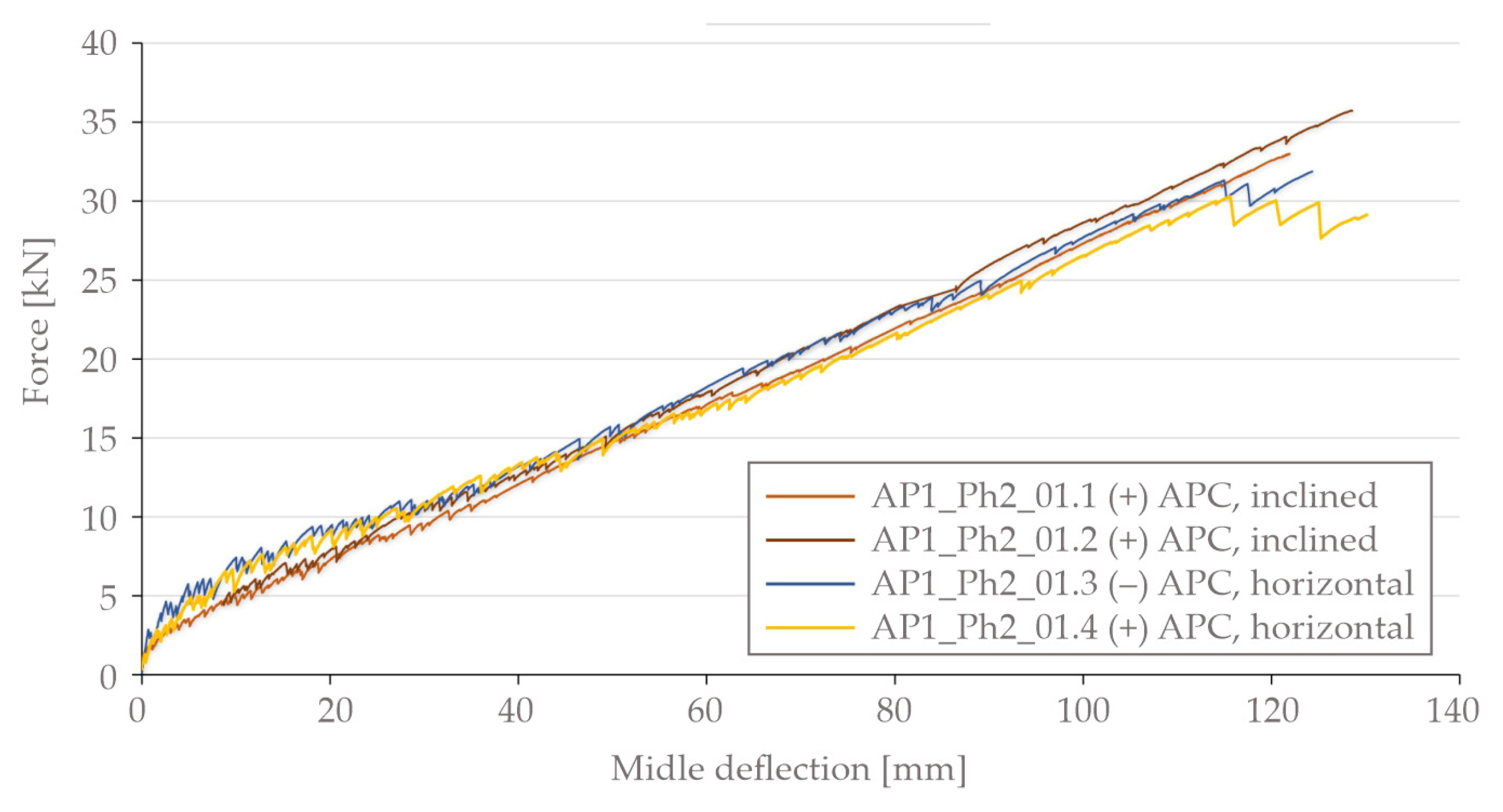
3.3.2. Force-Deflection Behavior

Figure 23 shows the midpoint deflection of the shells under the applied load. From the protocol of the experiments, it should be mentioned that the ranges for the maximal failure load and deflection for all the shells lay in-between 31.9 kN and 35.7 kN and 121.9 mm and 128.6 mm, respectively. The average values for the maximum failure load and midpoint deflection are 33.5 kN and 125 mm, respectively.
From the figure, it may be observed that the deflection curve possesses predominately linear behavior with a very minor non-linear range of up to approximately 2.5 kN of the applied load. This initial range indicates the initial bending stiffness of the shell elements with an uncracked concrete matrix (state I). Furthermore, the deflection curves with minor scatter between the values shows that the proposed manufacturing method gives good repetitiveness in developed TRC shell elements.
Also, it should be indicated that, as hoped, the ultimate load does not depend on the shell being produced under either negative or normal APC. Considering the nature of the derived failure mentioned above, clearly the ambient air pressure condition does not influence the strength of the textile reinforcement, though the difference between the shells produced horizontally and inclined is visible in the figure. Thus, the shells of series AP1_Ph2_01.3 and AP1_Ph2_01.4 (horizontal concreting) shows any higher bending stiffness in the range of the applied load between 0 kN and 15 kN. In addition, the curves for these shells tend to show somewhat higher force drops after each crack event. During the test of the negative APC shell, the crack formation was accompanied by significantly louder noise compared to the other shell tests. This may indicate that a higher amount of strain energy was released after each crack event in contrast to the samples produced with an inclined position as well as normal APC.

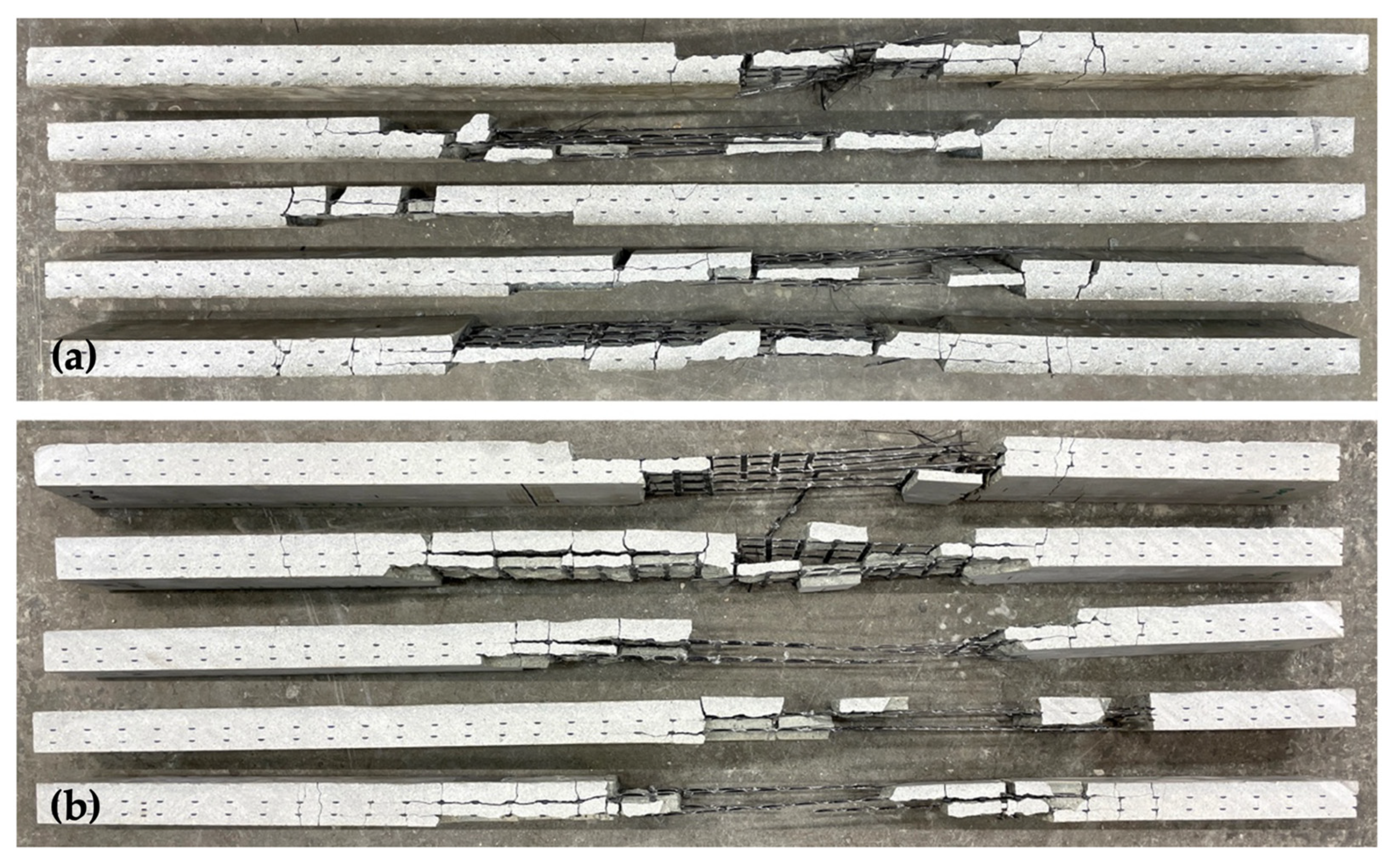
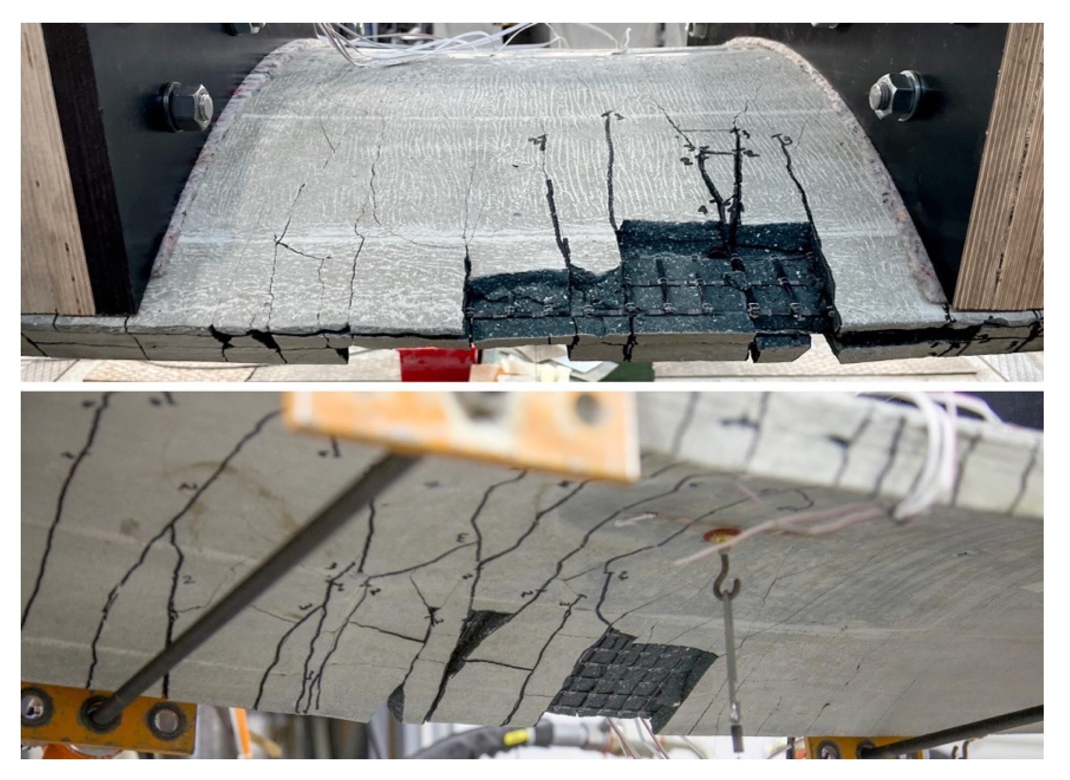
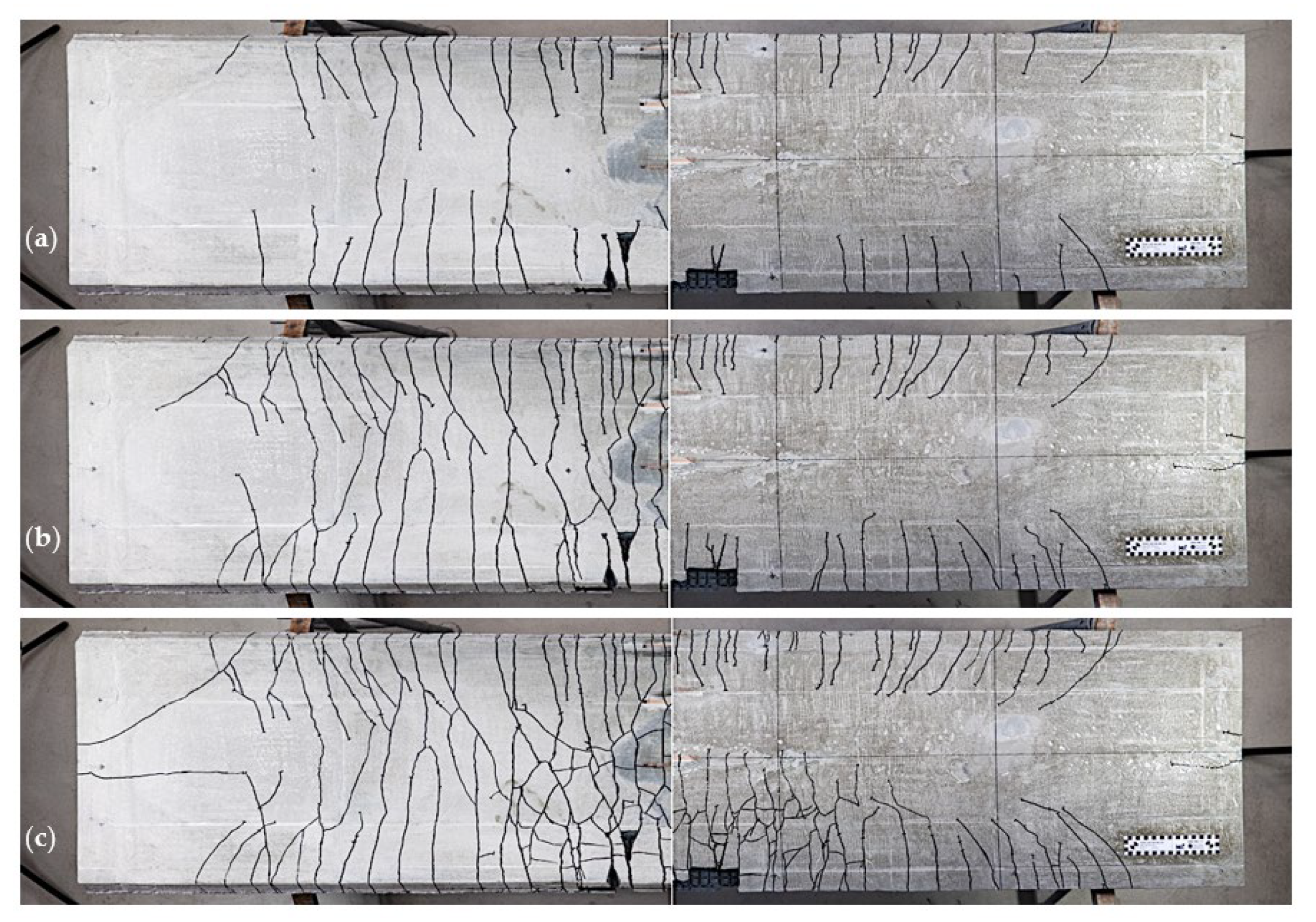
3.3.3. Crack Patterns

Figure 24 shows the typical resulting failure region from the top and bottom side. As can be seen, the failure happens in the tensile zone of the shell. The bottom surface of the shell is covered with cracks already, before the reaching the failure load. From this it is clear that the neutral stress line is located within the cross-section of the TRC shell. The propagation length of the crack from the top side of the shell matches the numerical analysis performed within the scope of the project and described in reference [12]. Furthermore, it can be indicated that the crack pattern follows the position of the transverse textile reinforcement yarns that is typical for the composite TRC.
From the shell tests, it can be deduced that the production technique has a minor influence on the crack pattern. Figure 25 shows the typical crack pattern for the bottom (left side of the figure) and top side (right side of the figure) of the shell element AP1_Ph2_01.3 derived for the three load increments of 15 kN, 25 kN and failure load. From Figure 25a, it can be seen that the main crack propagation phase belongs to the loading range of 0–15 kN and corresponds to the TRC material crack formation state IIa. As was recorded during the test, the consequent load steps mainly contribute to the increasing width of the already formed cracks and to the initiation of new cracks in the top part of the shell. While the load is further increased, new cracks are initiated due to the reason that the neutral line is rising up towards to the top side of the shell as a result of the stress redistribution within the shell element. Finally, from Figure 25c, a significant initiation of new cracks at the failure event is a result of the major deflection that comes after the reduction in the shell’s bending stiffness at that moment. Such an explosive manner of the crack formation and release of the accumulated strain energy leads to the splitting of the concrete matrix and the creation of the noticeably damaged area, which is visible in the figures. Also, the given crack patterns over the whole shell element indicate that the neutral line keeps its position along nearly the whole length of the shell with minor deviations at the supporting areas.

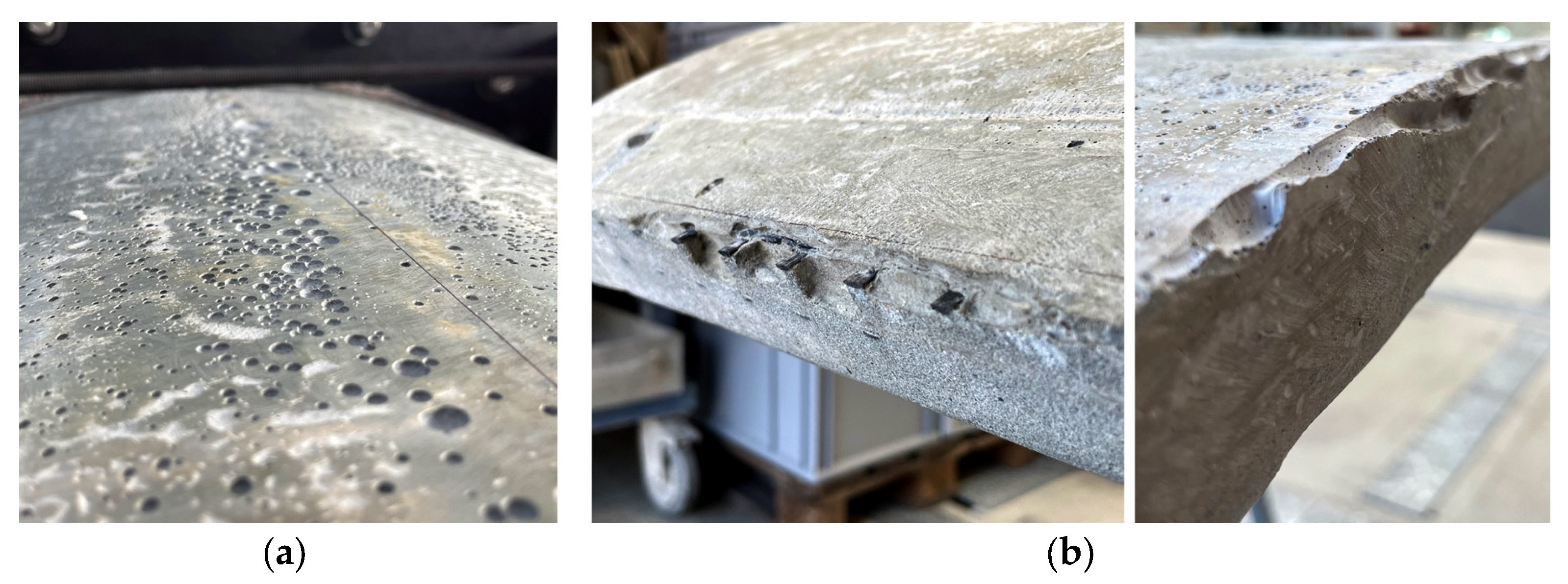
3.3.4. Observed Defects

The proposed production technique shows that both the horizontally oriented shells of series AP1_Ph2_01.3 and AP1_Ph2_01.4 possess generally accumulated air voids on top of the shell’s surface that form visible defects, see Figure 26a. However, the amount of air voids on the shell made under negative APC was somehow smaller than for the one produced under normal APC. The average diameter of the observed voids is close to 10 mm. Whether these defects are the reason for the somewhat lower failure loads of the horizontally concreted shells cannot be said with certainty, as the concrete itself usually has scattering properties, e.g., per batch. However, for elements with wall thicknesses significantly thinner than 4 cm, which should be the goal for future building with TRC, such defects will certainly have an impact.
Additionally, it was observed that the horizontal concreting under normal APC brought some other local defects in the edge areas of the element, which are visible in Figure 26b.

4. Discussion

4.1. Rating of the Vacuum Die Casting Method—Technical Aspects and Workflow

Regarding the proposed die casting method itself, some major observations should be discussed. First of all, on the one hand, it can be said that the workflow was somewhat more elaborate, especially the introduction of the concrete chamber into the vacuum chamber and the achievement of the air tightness of the whole facility, compared to conventionally casting. On the other hand, concreting with a horizontally positioned mould under negative APC was advantageous because of the lower number of voids, the absence of edge defects and the significant reduction in fresh concrete pressure.
Secondly, due to fast concrete hardening, 30 min of vacuum exposure for the high-performance freshly concreted samples was enough to reduce the deaeration to a minimum, even though the samples were under negative APC. Such behavior may eliminate the potential benefits that can be achieved for the concrete material properties. For potential future research with the aim of improving the concrete properties under negative APC, it may be recommended to use negative APC not only during the casting but during the mixing of the raw concrete components as well. First, the dry components need to be prepared under negative APC and a degasification procedure must be performed with a required amount of water. The degasification should be performed at least three times by reaching nearly 100% vacuum conditions. With consequent mixing under negative APC to prevent the introduction of a significant amount of air into the concrete mixture, the potential maximum improvement in material properties may be reached.
Another point regarding the utilization of the negative APC is the potential accumulation of air voids in areas with an increased density of the textile reinforcement or a higher ambient amount of formwork surfaces like edge or intersecting zones. Thus, as was described in Section 3.3.4, the noticeable air void accumulations on the element’s surface may be even with relatively high thicknesses like 40 mm. Consequently, with the further development of the current topic of thin-walled TRC structures, the accumulating of the air voids in more dense structures like TRC shells with thicknesses of about 10 mm may be more critical. As a result, air voids may completely fill the thickness of the TRC webs inside the complex structures and form unsolvable discontinuities in the shell structures.

4.2. Material Behavior of Samples Produced under Different APC

In the following, the results that were derived in the set of standard and large-scale tests shall be discussed. All the tests collected into the groups are provided further in the text:
  • Plain concrete tests. Considering the initial research results presented in reference [14], the detected reduced porosity in the samples casted under 80% negative APC promotes an increased compressive and bending tensile strength. In contrast, the samples concreted under 60% negative APC showed the opposite behavior. Taking into account the usual scatter when testing concrete, such diversity is not supposed to be a result of the different levels of the ambient pressure. Currently, we are preparing CT scans on small samples drilled from the tested specimen to obtain more information about the material’s structure and porosity. The scans will be performed at the Institute of Photogrammetry and Remote Sensing of TU Dresden as part of the fruitful collaboration within the TRR 280 project.
  • In the tensile tests on TRC, on the one hand, we achieved a comparable failure strength independent of the casting parameters. On the other hand, we observed different elongations in state IIa during crack development, visible in the horizontal shift of the mean value curves. Based on the available small amount of test results, no clear conclusion can be drawn. It seems that concreting under negative APC results in higher strains until the end of state IIa; the curve increase in state IIb is similar and parallel to the stress–strain behavior of a pure grid or yarn. The point is that such a shift indicates lower stiffness for the samples casted under negative APC, though it counteracts the results derived in the SPO tests that indicate a higher bond between the reinforcement and concrete matrix. Regarding this topic, additional systematic investigations are planned, varying the sample thickness and grade of APC in several steps.
  • SPO tests. The bond characteristics determined in the SPO tests also show some differences between the negative and normal APC, though the observed scatter makes it difficult to compare the results reliably. To determine the anchorage lengths, overlap or single yarn pull-out tests should be carried out.
  • Large-scale shell elements. All the four trials on the TRC shell elements show similar results regarding mechanical behavior. Therefore, the proof of concept of the proposed vacuum-assisted die casting method for the production of textile-reinforced concrete elements was successful.

5. Conclusions and Outlook

Generally, two important aspects, derived from the results presented above, may be concluded. The utilization of vacuum assistance for the proposed die casting method brings neither a noticeable decrease nor improvement in the material properties. Thus, it may be indicated that, for the purpose of the design of TRC structures, it is possible to use material properties derived from test under normal APC. The aim of the first experiments on the samples concreted using the vacuum-assisted die casting method was to prove the concept. We could show the proposed technology as a promising alternative to the conventional methods of production of TRC elements. Furthermore, considering the principles that were laid out on the basis of the given production method, it is theoretically possible to produce TRC structures of any envisioned complexity and, through this, achieve ultimate flexibility in the design of naturally inspired shell-like elements.
During the further course of our research project, we will perform some additional tests on the microstructures of small TRC samples obtained from the already tested elements, together with partners from the CRC/Transregio 280 project. The gained experimental data will be used for the examination, verification and enhancement of the production techniques and numerical calculation tool. Currently, we will update the vacuum chamber for the future vacuum-assisted production of more complex TRC elements in the next steps of the project. Furthermore, a systematic study regarding the tensile and bond characteristics of TRC produced under different conditions is planned. In the future, the further development of the shell-based segmentation of carbon-reinforced concrete elements and their production, and aspects of their environmental impact, will also be taken into account [33,34].

Author Contributions

Conceptualization, M.C., S.S. and I.V.; methodology, I.V.; validation, I.V. and S.S.; formal analysis, I.V.; investigation, I.V.; writing—original draft preparation, I.V. and S.S.; writing—review and editing, S.S. and I.V.; visualization, I.V. and S.S.; supervision, M.C. and S.S.; project administration, I.V.; funding acquisition, M.C. and S.S. All authors have read and agreed to the published version of the manuscript.

Funding

The authors greatly acknowledge the funding from the Deutsche Forschungsgemeinschaft (DFG, German Research Foundation) in the framework of the Collaborative Research Centre CRC/TRR 280 “Design Strategies for Material-Minimized Carbon Reinforced Concrete Structures—Principles of a New Approach to Construction” (project ID 417002380). The Article Processing Charges (APC) were funded by the joint publication funds of the TU Dresden, including the Carl Gustav Carus Faculty of Medicine, and the SLUB Dresden as well as the Open Access Publication Funding of the DFG.

Data Availability Statement

The data presented in this study are available on request from the corresponding author. The data are not publicly available due to the ongoing study.

Acknowledgments

The successful realization of the vacuum concreting facilities and the conduction of the tests in different scales was only possible with the broad support of our colleagues in the Otto Mohr Laboratory. We would like to especially emphasize the contributions of Rainer Belger and René Wallschläger (formwork and vacuum facility preparation), Jens Hohensee, Jens Lutz Reinhardt, Mario Polke-Schminke (concreting), Maik Patricny (preparation measurement technique), Doreen Sonntag, Michael Liebe, Katrin Dietz, Heiko Wachtel and Tino Jänke (test conduction and data recording), and Karoline Holz, as well as Sabine Wellner (lab coordination). Thanks to Arshad Kamal Chakkarathodi for his help in several stages of preparing the vacuum chambers and the shell production. Special thanks to the whole team of SLUB Makerspace and especially to Maik Jähne and Bastian Elsner for providing the production facilities and help in the development of the formwork and vacuum equipment components. We want especially highlight Stefan Gröschel, who photographed the different preparation steps and all the shell tests. Last but not least, we thank Peter Betz for the valuable discussions, Josiane Giese for providing tensile test result on plain yarns, and Liesen…alles für den Bau GmbH for the sponsoring of the super plasticizer.

Conflicts of Interest

The authors declare no conflict of interest.

References

  1. Triantafillou, T.C. (Ed.) Textile Fibre Composites in Civil Engineering; Woodhead Publishing: Duxford, UK; Elsevier: Amsterdam, The Netherlands, 2016. [Google Scholar] [CrossRef]
  2. Peled, A.; Bentur, A.; Mobasher, B. Textile Reinforced Concrete; Series: Modern Concrete Technology No 19; CRC Press: Boca Raton, FL, USA, 2017; Available online: https://www.taylorfrancis.com/books/mono/10.1201/9781315119151/textile-reinforced-concrete-alva-peled-barzin-mobasher-arnon-bentur (accessed on 10 August 2022).
  3. Pellegrino, C.; Sena-Cruz, J. (Eds.) Design Procedures for the Use of Composites in Strengthening of Reinforced Concrete Structures; State-of-the-Art Report of the RILEM TC 234-DUC 2016; Springer: Dordrecht, The Netherlands, 2016. [Google Scholar] [CrossRef]
  4. Koutas, L.N.; Tetta, Z.; Bournas, D.A.; Triantafillou, T.C. Strengthening of Concrete Structures with Textile Reinforced Mortars: State-of-the-Art Review. J. Compos. Constr. 2019, 23, 03118001-1–03118001-20. [Google Scholar] [CrossRef]
  5. Reichenbach, S.; Preinstorfer, P.; Hammerl, M.; Kromoser, B. A review on embedded fibre-reinforced polymer reinforcement in structural concrete in Europe. Constr. Build. Mater. 2021, 307, 124946. [Google Scholar] [CrossRef]
  6. JSCE. Recommendation for Design and Construction of Concrete Structures Using Continuous Fiber Reinforcing Material; Japan Society of Civil Engineers, Research Committee on Continous Fiber Reinforcing Materials: Tokyo, Japan, 1997. [Google Scholar]
  7. Dalalbashi, A.; Ghiassi, B.; Oliveira, D.V. Textile-to-mortar bond behavior: An analytical study. Constr. Build. Mater. 2021, 282, 122639. [Google Scholar] [CrossRef]
  8. Collaborative Research Centre/Transregio 280 (CRC/TRR 280) [Homepage]. Available online: https://www.sfbtrr280.de/en/ (accessed on 1 September 2023).
  9. Vakaliuk, I.; Frenzel, M.; Curbach, M. C3 Technology Demonstration House—CUBE—“From Digital Model to Realization”. In Inspiring the Next Generation—Proceedings of the IASS Annual Symposium 2020/21 and the 7th International Conference on Spatial Structures, Guildford, UK, 23–27 August 2022; Behnejad, S.A., Parke, G.A.R., Samavati, O.A., Eds.; Spatial Structures Research Centre of the University of Surrey: Guildford, UK, 2021; pp. 1827–1837. [Google Scholar]
  10. Beton- und Stahlbetonbau 2023, 118, S2—CUBE Das Carbonbetongebäude, 1–143. Available online: https://onlinelibrary.wiley.com/doi/10.1002/best.202390001 (accessed on 10 September 2023).
  11. Koschemann, M.; Vakaliuk, I.; Curbach, M. An Ultra-Light Carbon Concrete Bridge: From Design to Realisation. In Concrete Innovation for Sustainability—Proceedings of the 6th fib Congress, Oslo, Norway, 12–16 June 2022; Stokkeland, S., Braarud, H.C., Eds.; fib: Lausanne, Switzerland, 2022; pp. 2358–2367. [Google Scholar]
  12. Vakaliuk, I.; Scheerer, S.; Curbach, M. Numerical Analysis of the TRC Shells. Basic Principles. Struct. Concr. 2023. [Google Scholar]
  13. Brameshuber, W. Manufacturing Methods for Textile-Reinforced Concrete. In Textile Fibre Composites in Civil Engineering; Triantafillou, T., Ed.; Woodhead Publishing: Duxford, UK; Elsevier: Amsterdam, The Netherlands, 2016; pp. 45–59. [Google Scholar] [CrossRef]
  14. Vakaliuk, I.; Scheerer, S.; Curbach, M. Initial Laboratory Test of Load-Bearing Shell-Shaped TRC Structures. In Concrete Innovation for Sustainability—Proceedings of the 6th fib Congress, Oslo, Norway, 12–16 June 2022; Stokkeland, S., Braarud, H.C., Eds.; fib: Lausanne, Switzerland, 2022; pp. 675–684. [Google Scholar]
  15. Govignon, Q.; Bickerton, S.; Piaras, K. Liquid Composite Molding Processes. In Advanced Fiber-Reinforced Polymer (FRP) Composites for Structural Applications, 2nd ed.; Series in Civil and Structural Engineering; Bai, J., Ed.; Woodhead Publishing: Kidlington, UK, 2023; pp. 101–136. [Google Scholar] [CrossRef]
  16. Stefanescu, D.M. Casting, Metals Handbook, 9th ed.; ASM International: Kinsman Road Materials Park, OH, USA, 1988; Volume 15. [Google Scholar]
  17. Weisstein, E.W. “Invariant.” from MathWorld—A Wolfram Web Resource. Available online: https://Mathworld.Wolfram.Com/Invariant.html (accessed on 1 September 2023).
  18. Phaal, R.; Farrukh, C.J.P.; Probert, D.R. Technology Roadmapping—A Planning Framework for Evolution and Revolution. Technol. Forecast. Soc. Chang. 2004, 71, 5–26. [Google Scholar] [CrossRef]
  19. Butt, J. A Strategic Roadmap for the Manufacturing Industry to Implement Industry 4.0. Designs 2020, 4, 11. [Google Scholar] [CrossRef]
  20. ASM International. Casting—Design and Performance; ASM International: Kinsman Road Materials Park, OH, USA, 2009. [Google Scholar]
  21. Campbell, J. Complete Casting Handbook: Metal Casting Processes, Techniques and Design; Elsevier Ltd.: Amsterdam, The Netherlands, 2011. [Google Scholar]
  22. Chul, K.J.; Chang, H.J.; Chung, G.K. Vacuum Die Casting Process and Simulation for Manufacturing 0.8 mm-Thick Aluminum Plate with Four Maze Shapes. Metals 2015, 5, 192–205. [Google Scholar] [CrossRef]
  23. Carbon Concrete Composite e.V. Matrix-Datenblatt: C3-B2-HF-2-145-5; Carbon Concrete Composite e.V.: Dresden, Germany, 2016. [Google Scholar]
  24. Schneider, K.; Butler, M.; Mechtcherine, V. Carbon Concrete Composites C3—Nachhaltige Bindemittel und Betone für die Zukunft. Beton- und Stahlbetonbau 2017, 112, 784–794. [Google Scholar] [CrossRef]
  25. Dyckerhoff. C3 Carbon Concrete Composite—Binder for High Strength Carbon Concrete. 2017. Available online: https://www.dyckerhoff.com/documents/209745/0/424C3Bindemittel_GB.pdf/03fe968e-1139-e1ad-b06e-5c84f1bd221a (accessed on 1 September 2023).
  26. Solidian GmbH. Technical Product Data Sheet Solidian GRID Q85-CCE-21-E5 [Datasheet]; Solidian GmbH: Albstadt, Germany, 2023. [Google Scholar]
  27. DIN EN 196-1:2016-11; Prüfverfahren für Zement-Teil 1: Bestimmung der Festigkeit. Beuth: Berlin, Germany, 2016.
  28. Schütze, E.; Bielak, J.; Scheerer, S.; Hegger, J.; Curbach, M. Einaxialer Zugversuch für Carbonbeton mit textiler Bewehrung|Uniaxial Tensile Test for Carbon Reinforced Concrete with Textile Reinforcement. Beton- und Stahlbetonbau 2018, 113, 33–47. [Google Scholar] [CrossRef]
  29. Bielak, J.; Spelter, A.; Will, N.; Classen, M. Verankerungsverhalten textiler Bewehrungen in dünnen Betonbauteilen. Beton- und Stahlbetonbau 2018, 113, 543–550. [Google Scholar] [CrossRef]
  30. Hatzfeld, T.; Jana, G.B.; Christoph, S.; Edeltraud, G.; Marzia, T. Environmental Assessment of Carbon Reinforced Concrete Recycling Options. In Concrete Innovation for Sustainability—Proceedings of the 6th fib Congress, Oslo, Norway, 12–16 June 2022; Stokkeland, S., Braarud, H.C., Eds.; fib: Lausanne, Switzerland, 2022; pp. 891–900. [Google Scholar]
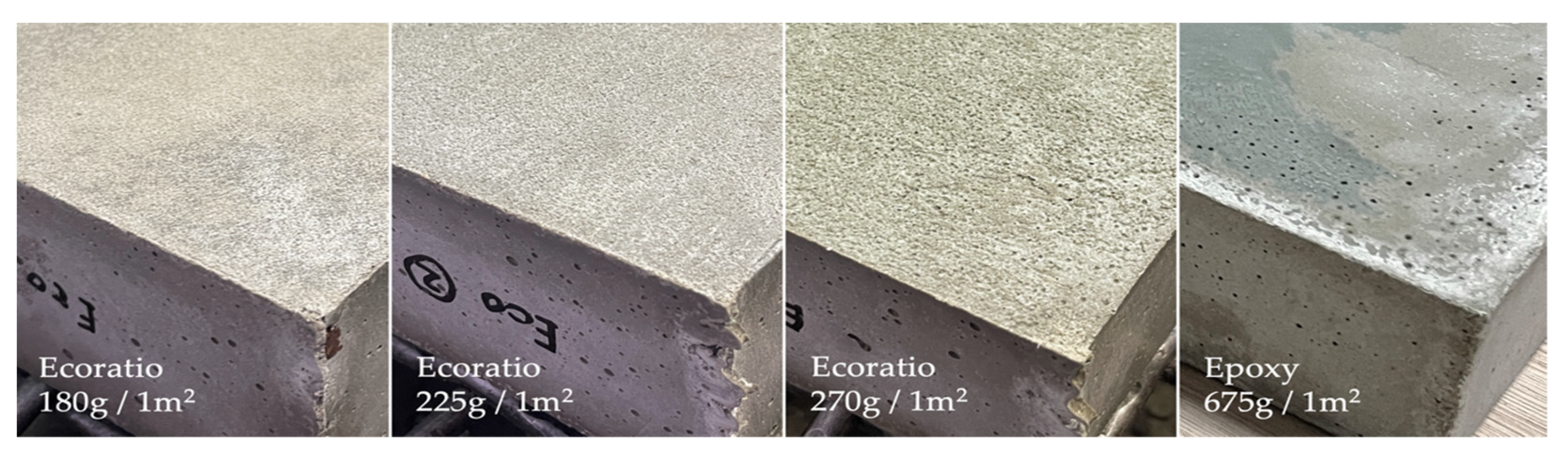
  31. Ecoratio Betonpro Wax G [Datasheet]. Available online: https://ecoratio.com/ (accessed on 1 September 2023).
  32. DIN EN 12390-13:2021-09; Prüfung von Festbeton—Teil 13: Bestimmung des Elastizitätsmoduls unter Druckbelastung (Sekantenmodul); Deutsche Fassung EN 12390-13:2021. Beuth-Verlag: Berlin, Germany, 2021.
  33. Stoiber, N.; Hammerl, M.; Kromoser, B. Cradle-to-gate life cycle assessment of CFRP reinforcement for concrete structures: Calculation basis and exemplary application. J. Clean. Prod. 2020, 280, 124300. [Google Scholar] [CrossRef]
  34. Backes, J.G.; Del Rosario, P.; Petrosa, D.; Traverso, M.; Hatzfeld, T.; Günther, E. Building Sector Issues in About 100 Years: End-of-Life Scenarios of Carbon-Reinforced Concrete Presented in the Context of a Life Cycle Assessment, Focusing the Carbon Footprint. Processes 2022, 10, 1791. [Google Scholar] [CrossRef]
Figure 1. Fundamental project idea for innovative material-efficient TRC structures; photo: Sylke Scholz, Dresden.
Buildings 13 02641 g001
Figure 2. Working principles to be considered in TRC die casting method; graphic: Iurii Vakaliuk.
Buildings 13 02641 g002
Figure 3. Possible orientation of a TRC element during concreting: (a) orientation when top and bottom shell may have unfavorable conditions, (b) orientation when mainly arch-like elements subjected to unfavorable conditions, (c) orientation when minor flat areas and partially arch-like areas subjected to unfavorable conditions; graphic: Iurii Vakaliuk.
Buildings 13 02641 g003
Figure 4. Guidelines that the design solution of the concrete and vacuum chambers need to follow: (a) free-form TRC structure within the chambers, (b) vacuum chamber prepared for multiple concrete chamber sizes, (c) influence of the deformation of the chambers, (d) prevention from the secondary saturation with air; graphic: Iurii Vakaliuk.
Buildings 13 02641 g004
Figure 5. Assembly of the concrete chamber with main constituent parts; graphic: Iurii Vakaliuk.
Buildings 13 02641 g005
Figure 6. Assembly of the vacuum chamber with main constituents; graphic: Iurii Vakaliuk.
Buildings 13 02641 g006
Figure 7. Small vacuum chamber (a) with moulds for standard samples inside and (b) active deaeration of the fresh concrete; photos: Iurii Vakaliuk.
Buildings 13 02641 g007
Figure 8. (a) Prototype vacuum chambers, used for first concreting trials (series AP1_ph1); (b) Control of filling level; (c) Observed active deaeration (vertical view down on the rising fresh concrete); Photos: Iurii Vakaliuk.
Buildings 13 02641 g008
Figure 9. Planning CNC production of the XPS blocks using Rh + GH environment; graphic: Iurii Vakaliuk.
Buildings 13 02641 g009
Figure 10. Mould from connected XPS blocks; photo: Iurii Vakaliuk.
Buildings 13 02641 g010
Figure 11. Comparison of the different types and amounts of release agent; photos: Iurii Vakaliuk.
Buildings 13 02641 g011
Figure 12. General structure and constituents of space holders for TRC; graphic: Iurii Vakaliuk.
Buildings 13 02641 g012
Figure 13. Investigated concreting types of the TRC shells; (a) Concreting with an inclination of approx. 10° (normal APC); (b) Concreting in horizontal position (normal APC); (c) Concreting horizontally (negative APC); Graphic: Iurii Vakaliuk.
Buildings 13 02641 g013
Figure 14. Concrete chamber ready for installation (a) and installed into the big vacuum chamber (b), prepared to perform concreting under negative APC; photos: Iurii Vakaliuk.
Buildings 13 02641 g014
Figure 15. Stress–strain relation and derived Young’s modulus from compression tests on concrete cylinders manufactured under normal and negative APC; graphic: Iurii Vakaliuk and Silke Scheerer.
Buildings 13 02641 g015
Figure 16. Tensile tests on TRC: (a) sample geometry; (b) 40 mm thick samples before testing (view on cross section); (c) Sample during testing; Graphic: Silke Scheerer, photos: Iurii Vakaliuk.
Buildings 13 02641 g016
Figure 17. Results from tensile tests on TRC samples concreted under different conditions: (a) Mean values, supplemented by linear relations based on the elastic moduli from the data sheet (grid) and from yarn tests (minimum, maximum and mean values); (b) Sample from series AP1_Ph2_01.3—60% vacuum in the moment of failure; (c) Single values, series AP1_Ph2_01.3—normal APC; (d) Single values, series AP1_Ph2_01.3—60% vacuum; Photo: Iurii Vakaliuk, graphics: Iurii Vakaliuk and Silke Scheerer.
Buildings 13 02641 g017
Figure 18. Damaged samples after the tensile test: (a) manufactured under normal APC and (b) manufactured under negative APC; photo: Iurii Vakaliuk.
Buildings 13 02641 g018
Figure 19. SPO tests on TRC: (a) sample geometry; (b) samples during testing; graphic: Silke Scheerer; photos: Michael Liebe.
Buildings 13 02641 g019
Figure 20. Stress–crack opening relation of the samples concreted under normal and negative APC; graphic: Iurii Vakaliuk and Silke Scheerer.
Buildings 13 02641 g020
Figure 21. TRC shells test sensors set-up; graphic: Iurii Vakaliuk.
Buildings 13 02641 g021
Figure 22. Set-up of 6-point bending test on TRC shells; photo: Stefan Gröschel.
Buildings 13 02641 g022
Figure 23. Midpoint deflection–force diagram for the TRC shells during 6-point bending test; graphic: Iurii Vakaliuk and Silke Scheerer.
Buildings 13 02641 g023
Figure 24. Typical failure mode of the TRC shell; photo: Stefan Gröschel, Iurii Vakaliuk.
Buildings 13 02641 g024
Figure 25. Typical crack pattern during and after 6-point bending test—bottom view on the left and top view on the right—at load steps of (a) 15 kN and (b) 25 kN as well as (c) at failure load; photos: Iurii Vakaliuk.
Buildings 13 02641 g025
Figure 26. Observed voids (a) and edge defects (b) of TRC shell concreted horizontally under normal APC (series AP1_Ph2_01.4); photos: Iurii Vakaliuk.
Buildings 13 02641 g026
Table 1. Test program—amount (and age [d]) of specimens.
Kind of TestAPC
Condition (a)
AP1_Ph1 (c)AP1_Ph2
_01.1 (c)
AP1_Ph2
_01.2 (c)
AP2_ST
_02 (c)
AP1_Ph2
_01.3 (c)
AP1_Ph2
_01.4 (c)
Plain concrete
Bending tensile and compressive strength (prism)(+) APC3 (b) (28)3 (b) (29)3 (b) (29)3 (b) (28)3 (b) (28)3 (b) (28)
(−) APC---3 (b) (28; 80%)3 (b) (28; 60%)-
E-modulus (cylinder)(+) APC---3 (31)--
(−) APC---3 (31; 80%)--
Compressive strength and σ-ε relation (cylinder)(+) APC----3 (29) -
(−) APC----2 (29; 60%)-
TRC
Uniaxial tensile strength(+) APC6 (28)---5 (28)-
(−) APC6 (28; 80%)---5 (28; 60%)-
Bond characteristics (SPO)(+) APC----5 (28)-
(−) APC----5 (28; 60%)-
TRC shell ------
6-point bending test(+) APC-1 (29)1 (29)--1 (28)
(−) APC----1 (28; 60%)-
Concreting
position
-inclinedinclined-horizontalhorizontal
(a) (+) means “normal” and (−) negative APC; (b) Here, the quantity of bending tensile tests is given which equals half of compression tests on prisms; (c) Test series were designated and numbered according to the working plan in the project proposal. “AP1/2” stands for the work package no. 1 or 2, “Ph1/2” means phase 1 or 2 within a work package. The numbers “01” means shell type no. 01, the following numbers “1–4” count the single shell tests. “ST” indicates a set of standard tests to determine the material properties, here as a first step in work package 2.
Table 2. Composition of C3-B2-HF-2-190-2 concrete.
Raw MaterialsQuantity [kg/m3]
Binder compound (a)815
Quartz sand 0.06/0.2340
Sand 0/2965
Superplasticizer (b)17
Water190
(a) BMK-DS-1 by Dyckerhoff GmbH, Germany [25]; (b) Currently we use LIESEN Superplasticizer 877 by Liesen (Bau GmbH, Wehr, Germany).
Table 3. Properties of the carbon fibre mat solidian GRID Q85-CCE-21 [26].
PropertyLongitudinalTransversal
Fibre cross-sectional area of fibre strand [mm2]1.811.81
Fibre cross-sectional area of mat [mm2]85.485.6
Roving axis distance (grid with) [mm]2121
Mean tensile strength (a), (b) [MPa]≥3950≥4250
Characteristic tensile strength (a), (b) [MPa]≥3050≥3250
Average Young’s modulus (b) [MPa]≥251,500≥254,000
(a) Short time value [25]; (b) Regarding fibre cross-sectional area.
Table 4. Bending tensile and compressive test results from prisms.
PropertiesAP2_ST_02AP1_Ph2_01.3
APC(+)(−) 80%(+)(−) 60%
Mean density [kg/m3]2320233023302330
Mean bending tensile strength (single values) [MPa]11.6
(10.3, 11.9, 12.6)
12.1
(13.2, 11.4, 11.8)
14.9
(13.4, 15.6, 15.5)
13.2
(13.8, 12.7, 13.1)
Mean compressive strength (single values) [MPa]95.0
(101.0, 95.1, 89.3,
95.1, 99.2, 90.4)
98.0
(91.8, 105.3, 92.9,
97.1, 100.6, 100.2)
108.1
(112.2, 113.3, 111.1,
107.5, 105.6, 98.9)
101.1
(100.5, 110.3, 96.1,
104.3, 101.2, 94.6)
Table 5. Compressive strength and elastic modulus determined on concrete cylinders.
PropertiesAP2_ST_02AP1_Ph2_01.3
APC(+)(−) 80%(+)(−) 60%
Mean density [kg/m3]2350234723572315
Mean compressive strength
(single values) [MPa]
121.1
(119.9; 123.6; 119.8)
124.1
(122.3, 124.8, 125.3)
106.6
(110.0, 103.4, 103.3)
113.3
(113.5, 113.0)
Mean elastic modulus
(single values) [MPa]
42,100
(41,900, 42,600, 41,800)
42,600
(43,500, 42,000, 42,300)
42,350 (a)
(a) mean value, determined from σ-ε relations.
Disclaimer/Publisher’s Note: The statements, opinions and data contained in all publications are solely those of the individual author(s) and contributor(s) and not of MDPI and/or the editor(s). MDPI and/or the editor(s) disclaim responsibility for any injury to people or property resulting from any ideas, methods, instructions or products referred to in the content.

