Article

Experimental Assessment and Validation of the Hygrothermal Behaviour of an Innovative Light Steel Frame (LSF) Wall Incorporating a Monitoring System

1
University of Coimbra, CERIS, 3030-289 Coimbra, Portugal
2
Itecons, 3030-289 Coimbra, Portugal
3
CeNTI—Centre for Nanotechnology and Smart Materials, 4760-034 Vila Nova de Famalicão, Portugal
4
University of Coimbra, CERIS, Department of Civil Engineering, 3030-790 Coimbra, Portugal
*
Author to whom correspondence should be addressed.
Buildings 2023, 13(10), 2509; https://doi.org/10.3390/buildings13102509
Submission received: 16 August 2023 / Revised: 21 September 2023 / Accepted: 29 September 2023 / Published: 3 October 2023
(This article belongs to the Special Issue Advances in Sustainable Building Materials)

Abstract

:
Currently, the construction sector is witnessing a growing demand for lightweight solutions, which can be justified by the need to adopt high-performance solutions and the fact that the industry is struggling with a shortage of skilled labour. In this sense, this study focuses on a novel and flexible building wall system, constructed using an innovative extensible LSF profile. To enhance its functionality, a monitoring system comprising printed sensors was integrated into the wall. These sensors underwent a thorough verification process. To evaluate the hygrothermal performance of the complete LSF wall solution and validate the novel monitoring system, an extensive ageing test focused on heat/rain, freeze/thaw cycles was conducted on a large-scale wall prototype. Additionally, this research introduces a novel approach by simulating exceptional solar radiation conditions, surpassing the standard cycles outlined in EAD 040083-00-0404, for the first time in this kind of solution. The results cover the measurements taken inside the building system using the incorporated monitoring system. Additionally, supplementary external temperature and heat flow sensors were used to determine the thermal transmittance. Visual and thermography inspections were also carried out. The findings reveal no instances of failures or defects that could potentially impact the hygrothermal behaviour of the system. The hybrid LSF constructive solution leads to more stable temperatures on the inner surface. The presence of direct solar radiation can raise surface temperatures by up to 5 °C compared to surfaces not exposed to such radiation, even when a light-coloured surface is used. The monitoring system worked correctly. In conclusion, the innovative profile proved to be resistant to hygrothermal cycles and the monitoring system developed is efficient.

1. Introduction

The trend of innovation in the construction sector is to develop new materials and constructive solutions that are more efficient, durable, safe, and that provide comfort and hygiene conditions without increasing the cost of construction and maintenance of the building throughout its service life [1,2]. Construction is one of the most important economic and social development sectors. However, the main challenge that we are facing today is to keep a high level of activity to ensure countries develop as much as possible, but with the smallest environmental impact possible. In fact, the need to prevent the excessive energy consumption of buildings and reduce the waste of construction works, and the lack of labour, are the biggest challenges facing the construction industry, according to several studies [2,3,4,5]. One of the approaches to address these challenges is to develop more efficient and sustainable innovative construction technologies. In this context, prefabricated construction, which has been growing, is seen as an important strategy for the sustainability of the construction [3,6,7,8,9].
Prefabricated construction is a process in which building components are fabricated in a factory and transported to a construction site where the components are assembled to create buildings. It is based on manufacturing elements, panels, or modules [10] which may be made of common construction materials such as steel, concrete, or wood.
Prefabricated construction can imply a substantial reduction of resources compared with conventional construction. It can lead to a decrease in embodied energy (up to −40%), end of Life (up to −90%), and life cycle impacts (up to −10%) [8]. In the study [11], where traditional construction is compared with modular construction through two real modular buildings, it was found that the modular constructive technologies used allowed a reduction of between 46% and 87% in waste generation, 66% and 70% in water consumption, 25% and 50% in noise reduction, 32% and 50% in speed of construction, and over a 100% improvement in on-site labour productivity. The advantages of prefabricated construction in relation to traditional construction are detailed in the scientific literature [5,12,13,14,15], which often highlights the rapid construction, the lower needs for on-site space, the reduction of water consumption, the lower construction and demolition waste, as well as the easier disassembly and recyclability potential at the end of life.
One of the prefabricated building technologies that is emerging as a real option is light steel framing (LSF) [8]. LSF is a building construction technique that uses dry materials such as cold-formed steel (CFS) sections with some load-bearing capacity, sheeting panels, and insulation materials. Other materials are necessary, such as screws, membranes for waterproofing and air tightness, and finishing layers [16]. The LSF façade walls can be classified into three types (cold, hybrid, and warm), depending on the position of the thermal insulation [16,17,18], as shown in Figure 1. The cold frame construction includes only insulation material inside the wall cavity, while in the warm frame construction, the insulation is completely shifted to the external side of the wall. Typically, the solution is ETICS (External Thermal Insulation Composite Systems). Finally, in the hybrid frame construction, the insulation is applied both inside the wall cavity and externally.
This constructive system is being adopted more often all over the world, as stated by several authors [1,16,19,20,21,22,23] as a result of the advantages mentioned above. Moreover, Lim et al. [12] noted that the use of cold-formed steel in modular buildings can significantly reduce the project cost (by up to 23%) while simultaneously providing better storey shear and storey drift, with the environmental and social impact also being lower than for traditional construction. These advantages meet the needs of the construction sector, which is looking for new construction methods and solutions that require less labour and are faster, more sustainable, and help to optimize construction methods.
Despite the numerous advantages, the LSF system has some disadvantages related to the lack of adaptability, namely in situations where it is necessary to make some adjustments on site. This leads to the production of waste derived from the need for cuts and splices, the lack of specialized labour and the risk of durability failure if the water-tightness is not guaranteed. In LSF systems the risk of condensation and possible air and water infiltration can cause corrosion of the metallic elements of the structure, as well as the appearance of mould, thus jeopardizing the construction elements’ durability. Minor defects in this type of modern construction can lead to severe degradation including corrosion, mould growth and accelerated weathering regimes [20]. Continued corrosion of the metal can occur if the relative humidity is greater than 80% while the temperature is above 0 °C at the surface. With regard to mould growth, studies point to a maximum relative humidity limit of 75% to prevent it, as reported by Zhan et al. [19] based on studies [24,25,26].
The increased use of LSF motivates the industry and researchers to develop more efficient and sustainable systems [27]. These developments include the introduction of innovative profiles as mentioned in [28] where several examples are presented. These include prestressed CFS beams [29,30], optimized folded-flange section [31] and super-sigma section [32], hollow flange sections [33,34,35,36,37], rivet fastened hollow flange sections [38,39], and gapped built-up sections [40,41].
Based on a research project led by the industry and supported by R&D centres, an innovative LSF system incorporating a monitoring system was developed. Unlike commercial static profiles, the steel profile developed is intended to be extensible, which minimizes the disadvantages of current profiles regarding flexibility and adaptability through the introduction of extensibility capacity. This new LSF profile allows for faster construction, reducing the waste of construction and labour required due to the flexibility introduced, which leads to an easy adjustment to the particularities and design requirements without the need for multiple cuts, connections between profiles, or splices. Also, the transport and assembly are optimized with this innovative profile. The monitoring system consists of temperature and water detection sensors developed through screen-printing techniques.
The experimental validation of innovative materials and large-scale constructive solutions is fundamental, as noted by Abdelmageed and Zayed [42]. Regarding the characterization of the hygrothermal performance, several researchers have conducted experimental work on LSF systems to present scientific works carried out in this context. In the following paragraphs, some of these studies are presented.
Zhan et al. [19] assessed the hygrothermal performance of typical lightweight steel-framed wall assemblies in hot–humid climate regions through 10 months of monitoring under real-world environmental conditions and verified that the studied wall assembly can become wet when the weather is humid, or the indoor environment is air-conditioned. In another study, Zhan et al. [20] conducted fundamental research on the hygrothermal performance of LSF wall assemblies by characterizing the hygrothermal responses under hot–humid climatic conditions, validating simulation models. This validation focused on humidity and temperature measurements. Four typical and full-scale LSF wall assemblies were tested and compared using two room-like test cubes in Guangzhou, a hot–humid city in China. The authors concluded that, generally, wall assemblies with ventilated rainscreen and external insulation exhibited the best hygrothermal response in a hot–humid climate Still driven by Zhan et al. [43], the hygrothermal performance of an LSF wall in hot–humid regions was optimized using orthogonal experimental design and a validated simulation model. In this study, a solution comprising six construction layers was explored in order to reduce the moisture risk. In this study, the authors concluded that, to reduce moisture risks, LSF wall assemblies should generally minimize the infiltration of outdoor moisture as much as possible while enhancing internal drying capacity. Santos and Mateus [21] carried out an experimental assessment of thermal break strips performance in load bearing and non-load bearing LSF walls by measuring the thermal performance of twenty LSF wall configurations, using the flow meter method under controlled laboratory conditions. The authors found that the use of heat flux sensors (one on each side of the wall sample) significantly reduced the expected uncertainty range. For the determination of the thermal transmittance of LSF walls, Atsonio et al. [1] presented two new methods for the in situ measurement of the overall thermal transmittance of cold frame LSF walls. These new methods combine the analysis of the examined wall using thermal images with the recording and processing of indoor/outdoor air temperature and heat flux. The results of the in situ measurements were in a good agreement with the theoretical values. Roque et al. [13] assessed the opportunities and limitations of LSF and hollow brick masonry constructive systems in terms of minimizing energy consumption and providing a comfortable indoor environment during the hot season based on a long-term programme of experiments monitoring the indoor temperature associated with the operation of the heating equipment. The results revealed that the LSF test cell is more responsive to the external weather stimulus and, therefore, more susceptible to the nocturnal temperature drop and overheating during warmer conditions. Martins et al. [44] assessed the thermal performance of two types of boards applied to LSF building systems. Comparative analyses and measurements of thermal performance were carried out by spectrophotometer tests to calculate solar absorptance, by infrared thermography to obtain surface temperatures, and by evaluation of external and internal dry bulb temperatures with data loggers and prototype instrumentation. Friis et al. [45] conducted a study to assess the hygrothermal performance of exterior walls in an arctic climate. This study included detailed measurements and simulations of a test facility. The authors analysed five wall construction solutions, including a steel solution with mineral wool in the cavity. This solution proved to be suitable for the Arctic climate. Temperature and relative humidity measurements were taken using sensors placed within the test facility. Santos et al. [46] evaluated the thermal transmittance of three different LSF walls experimentally, numerically, and analytically. The experimental measurements were performed using a hot and a cold climatic chamber and the Heat Flow Meter (HFM) method. The authors concluded that given the thermal insulation continuity of the ETICS, the steel studs thermal bridging effect was significantly reduced.
Most of these types of experimental programmes use cell tests that are subjected to a specific real climate during a certain period. Replicability tests are not feasible with this type of setup due to the variability of conditions. This study introduces the utilization of a climatic chamber that not only simulates temperature, humidity, and rain, but also incorporates the simulation of solar radiation.
In this work, the research object is a building wall system made of an innovative extensible LSF profile incorporating a monitoring system composed of printed sensors. These sensors were subjected to verification. Concerning the evaluation of the hygrothermal behavior of the full wall solution and the validation of the monitoring system, a large-scale wall was subjected to ageing tests. The prototype was composed of both a cold and a hybrid solution and included a real window so that the test specimen had specific features. In addition to standard heat/rain and freeze/thaw cycles prepared according to EAD 040083-00-0404 [47], exceptional solar radiation simulations were also introduced. In Figure 2 is presented the methodology followed. The introduction of solar radiation during hygrothermal cycles aimed to make the hygrothermal assessment of constructive solutions more comprehensive and closer to reality. In this way, an innovation was introduced to laboratory hygrothermal evaluations, as the current practice involves conducting hygrothermal cycles without solar radiation.
The results include the measurements taken inside the building system, using the incorporated monitoring system (printed sensors), and those obtained using additional external temperature and heat flow sensors, which allowed for the determination of the thermal transmittance. Visual and thermography inspections were also carried out.
The work was part of a research project called SMARTLSF, which was led by the industry and supported by R&D centers. This research was performed by CeNTI (Centre for Nanotechnology and Smart Materials) and Itecons (Institute for Research and Technological Development in Construction, Energy, Environment, and Sustainability).

2. Materials and Methods

2.1. Description of the LSF Innovative Profile

The development of the LSF profile focused on introducing an innovative extensibility feature. This novel LSF solution consists of two steel profiles with a groove geometry that enables sliding movements when they are connected, as illustrated in Figure 3. This design feature facilitates the extension of the structural element by a maximum of 500 mm. The connection between the two profiles is achieved on-site by nailing them together along the overlapping zone. The design depicted in Figure 3 resulted from a conceptual study developed within the scope of the SMARTLSF project, and it was experimentally and numerically validated. This design has proven to be easily extensible and applicable in construction. The final system, composed of these profiles, offers the advantage of being dynamic in three dimensions, simplifying its transportation and installation. The flexibility introduced by the extensible profiles allows the LSF elements to easily adapt to the specific requirements and demands of the project without the need for multiple cuts or connections between profiles or joints.

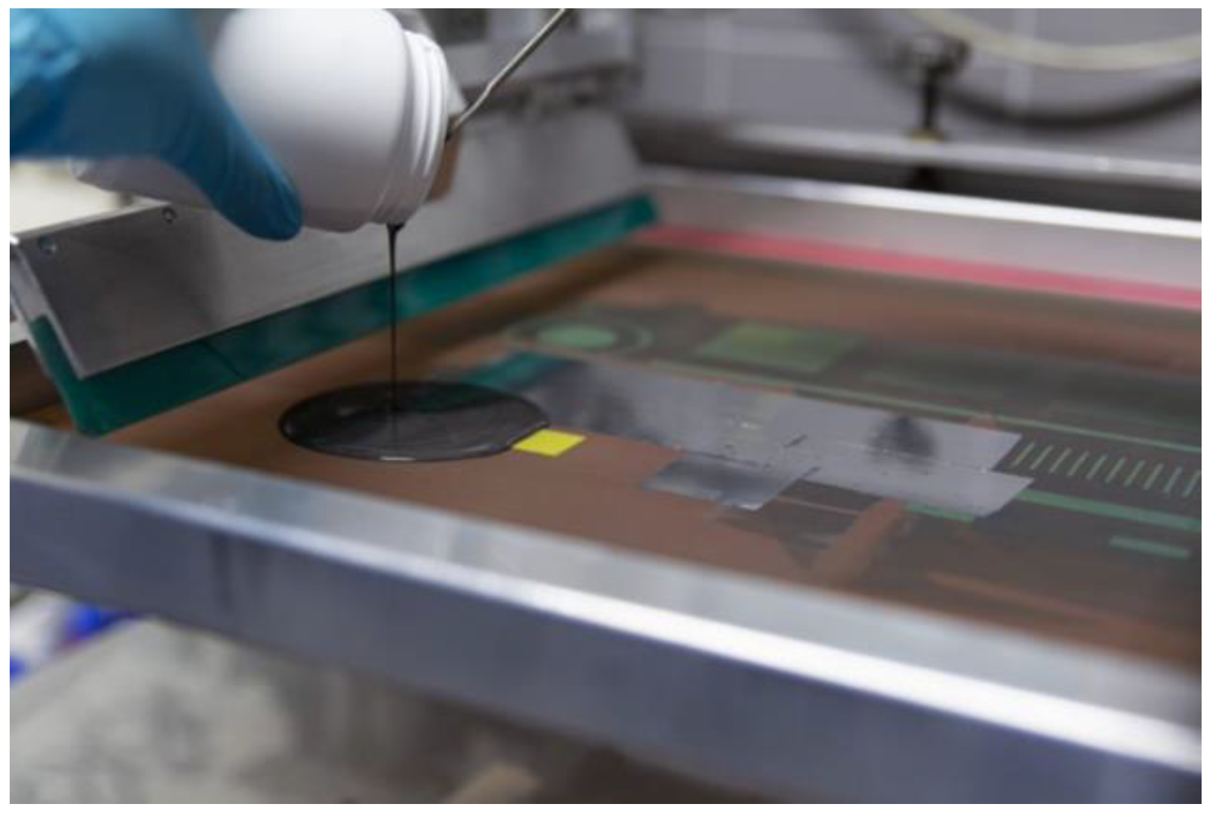
2.2. Development of the Hygrothermal Sensors

The sensors developed under the SMARTLSF project were based on screen-printing techniques. In this printing method, a porous screen mesh with the desired printing pattern is used as a stencil. When printing, a squeegee moves along the screen and applies enough pressure to force the ink paste to penetrate through the open mesh areas, therefore depositing it on the final substrate. The main advantage of this method is that it can significantly increase the production yield by upscaling to a roll-to-roll process. Figure 4 depicts the screen-printing equipment available at CeNTI that was used for the production of the sensors described below.
To proceed with the development of the printed temperature sensor, a thermoresistive principle was selected as the basis of operation. This principle is related to metallic materials whose electrical resistivity is dependent on the surrounding temperature and is commonly associated with linear behavior within a wide range of temperatures. Sensors were therefore screen-printed onto polyimide substrates using a commercial silver ink. The geometry of the sensor was designed to meet the desired characteristics (for example, sensitivity and overall area) by referring to the properties of the ink. Figure 5a presents an example of a printed sensor developed for temperature monitoring.
Regarding the water detection sensor, its transduction principle was based on a capacitive operation. In this case, the presence of water in the monitoring area of the sensor leads to a change in the dielectric constant of the medium, which is manifested through a change in the capacitance signal. The main advantage of this operation is that it does not require direct contact between the water and the conductive electrodes of the sensor, therefore improving the devices’ lifetime. To develop it, a commercial silver ink was selected to print the sensors’ interdigitated structure onto PET substrates, as shown in the example in Figure 5b.
These sensors were previously checked using a climatic chamber and small-scale tests specimens. The results are presented in Section 3.1.

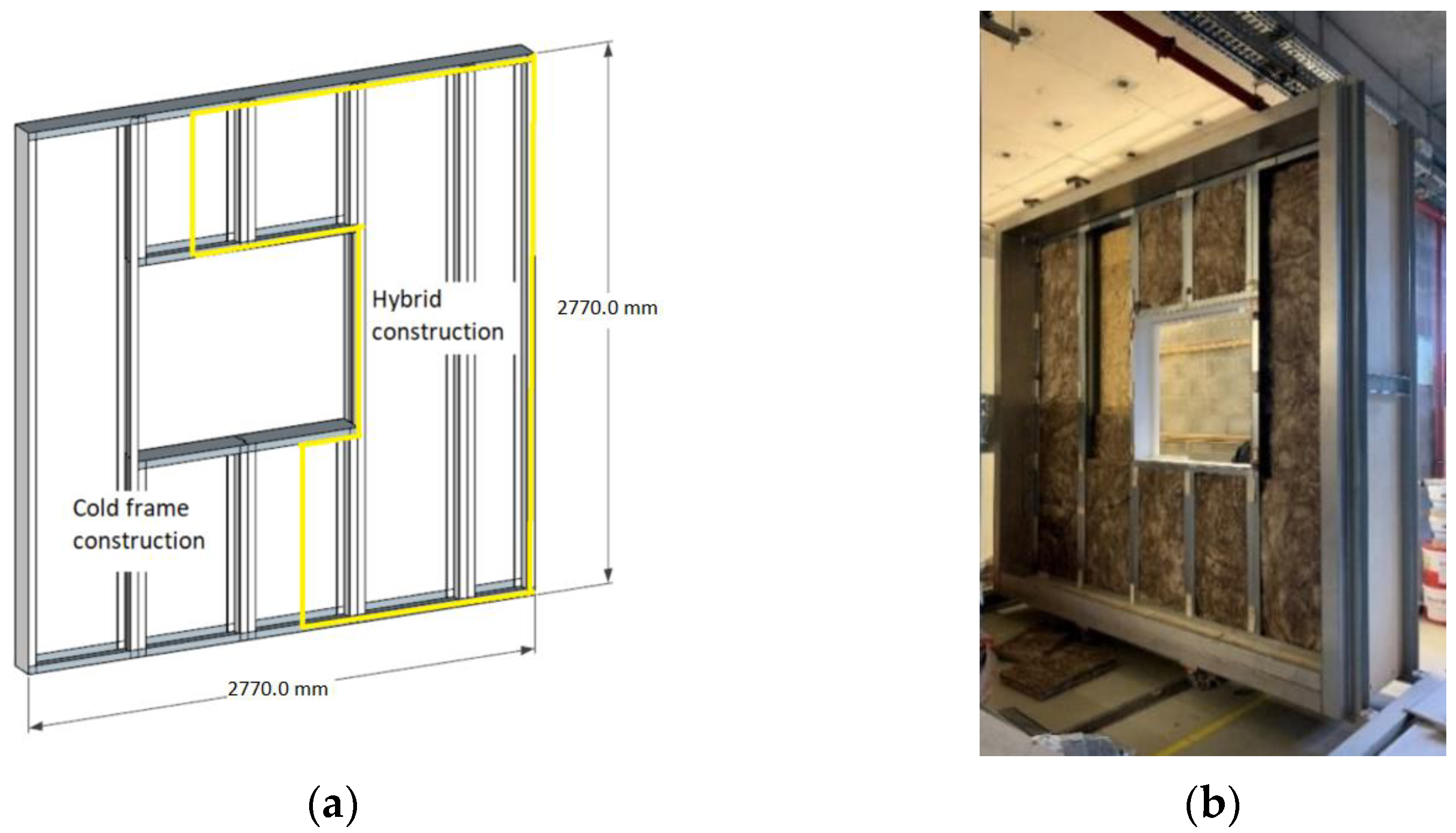
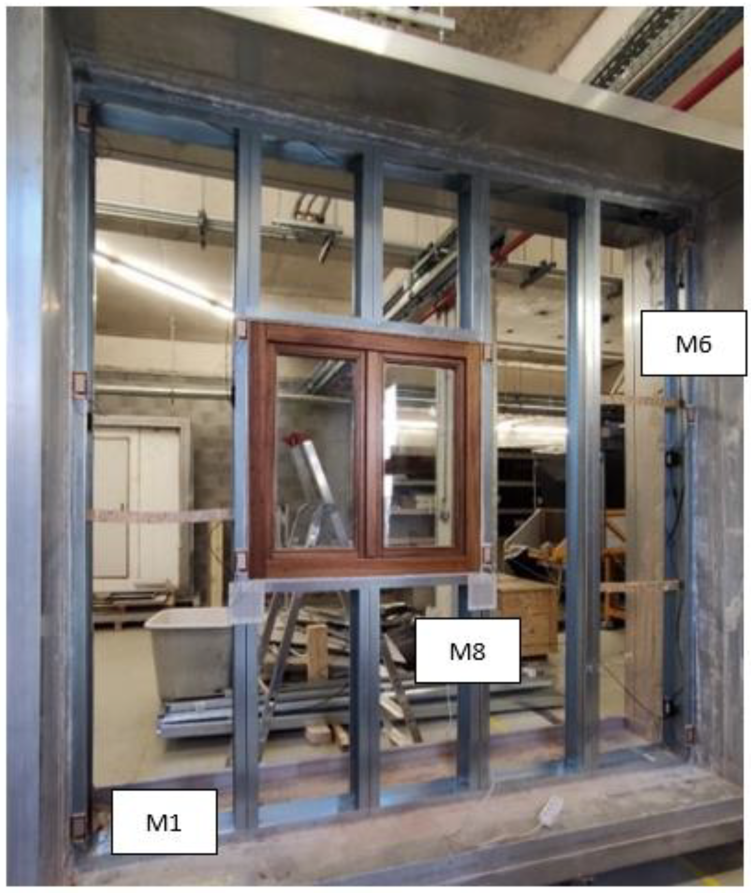
2.3. Description of the Test Specimen

The test specimen consists of a 2.77 m × 2.77 m LSF wall constructed using the innovative LSF profiles. The test specimen combined a cold frame construction and a hybrid construction, as depicted in Figure 6a. To study the details of its installation and assess the hygrothermal behavior in the vicinity of singularities (such as wall-window junctions), a wood-frame window was installed. Before starting the tests, the test specimen was cured for 28 days according to the instructions of EAD 040083-00-0404 [47].
Figure 6 presents the test specimen configuration.
The components of the test specimen and its characteristics are presented in Table 1. The selection of the components presented is in line with the constructive solutions of other similar studies, such as the studies [13,16,17,18,19,20], proving to be common components of light steel frame (LSF) constructive solutions. Regarding mineral wool, the choice for insulating the cavity is due to its advantages related to fire behavior.
Concerning the monitoring system, in the first stage, a strategic distribution of the monitoring modules and respective sensors was defined to gather valuable insights from the hygrothermal cycles. Two possible configurations were established for the modules: (i) printed temperature sensors, integrated in the external and internal surfaces of the metallic profile, and (ii) identical to (i), with the addition of printed water detection sensors, placed either on the external surface or on the interior of the structure, depending on the respective monitoring zone. A schematic of the modules’ distribution in the test specimen is shown in Figure 7, with the identification of the hybrid construction with ETICS.
Given this distribution proposal, a total of 10 modules were produced to incorporate in the smart structure for the hygrothermal tests. To accomplish that, 20 temperature sensors and 8 water detection sensors were prepared as described in Section 2.2, as well as the required control electronics. It should be noted that each module was composed of a dedicated printed circuit board (PCB) responsible for gathering the data from the relevant sensors. The final sensing structure is presented in Figure 8.
To install the printed sensors on the test specimen, they were first incorporated in strips of a functional composite component also developed under the SMARTLSF project, with improved acoustic and flame retardancy properties. A detailed view of three modules integrated into the test structure is shown in Figure 9. As can be seen, the sensing composite strips were installed directly on the metallic structure and each module was fitted with a casing that housed the respective PCB, in addition to an SHT commercial sensor for temperature reference.
For the correct operation of the smart system, the 10 modules were connected in series and with a gateway that was responsible for supplying energy to the entire system, as well as for gathering the acquired data from each module during the hygrothermal cycles. These data were subsequently analyzed to assess the performance of the innovative profiles, and the results are described in Section 3.
To monitor the temperature during the ageing tests under solar radiation and to estimate the U-value of the solutions, the specimen was also instrumented with commercial thermocouples and heat flux sensors. To assess the impact of solar radiation on the surface temperature, a set of standard thermocouples were installed as illustrated in Figure 10.
The thermal transmittance (U-value) was determined by installing thermocouples and heat flux sensors higher up the internal and external surface of the test specimen, as shown in Figure 11.

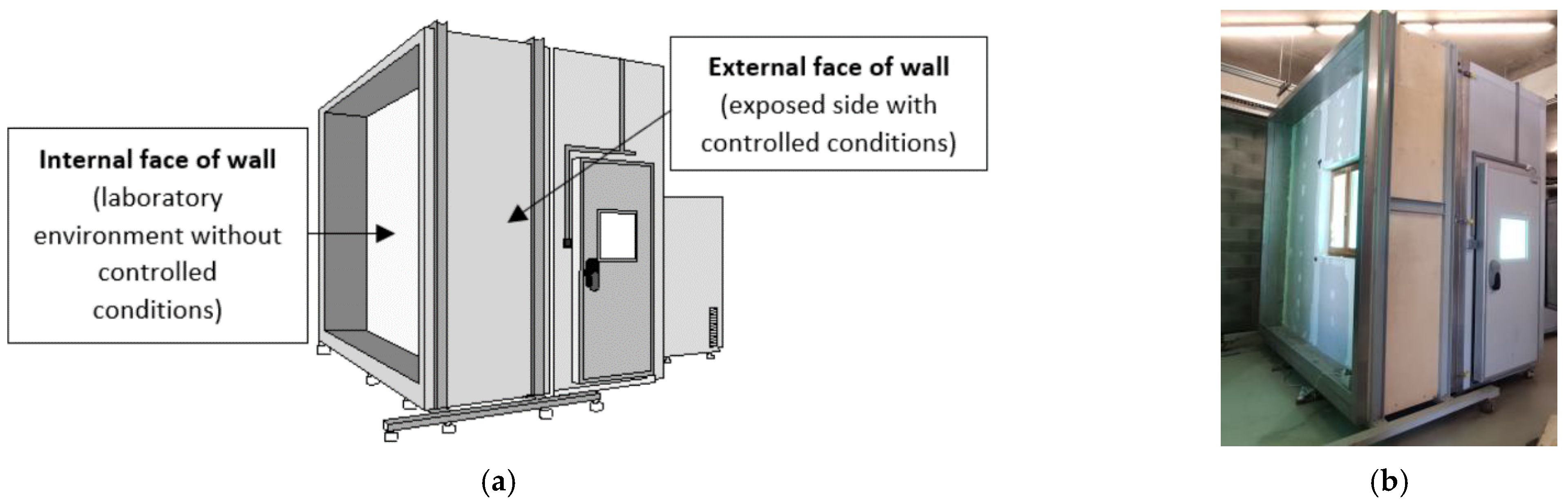
2.4. Description of the Test Apparatus

The hygrothermal cycles were carried out at Itecons facilities in a climatic chamber (FitoClima 1000 EC 50), with 14.5 m3 of conditioned volume, temperature range from −20 to 150 °C (±5 °C) and humidity from 10 to 98% (±10%), a water spraying system providing 1 L/min·m2. Figure 12 shows the test apparatus used for the experimental assessment of the hygrothermal behavior of the solution.
The apparatus for the radiation test consisted of two BF SUN 2500 W lighting systems, each with a metal halide lamp, Osram HMI 2500 W, and an electronic power supply unit with intensity control 40–100% was installed inside the hygrothermal chamber, 0.9 m from the test specimen surface. This artificial global radiation system meets the requirements for automobile industry ageing tests [48], simulating the wavelength spectral range of 230–3000 nm, which includes UV-C, UV-B, UV-A, visible and infrared radiation. The test area with homogenous solar radiation incidence can be seen in Figure 13.
Complementary to the experimental campaign based on the hygrothermal cycles and solar radiation, a visual inspection was carried out to assess the state of the LSF profiles in terms of warping, cracks, and other defects. Furthermore, an infrared thermography study using an infrared camera was carried out to evaluate the appearance of anomalies such as moisture, detachments, and others.
The specifications of the equipment and sensors used in the hygrothermal cycles tests are given in Table 2.

2.5. Description of the Test Procedures

The test procedure included three stages: stage 1 with steady state conditions in order to experimentally determine the U-value of the wall; stage 2 consists of the ageing hygrothermal cycles; and stage 3 consists of an innovative ageing test that includes solar radiation.
The U-value was calculated according to ISO 9869-1—Thermal insulation—Building elements. In situ measurements of thermal resistance and thermal transmittance [49]. According to this standard, the U-value is determined as follows:
U = j = 1 n q j j = 1 n T i j T e j
where:
  • qi, density of heat flow [W/m2];
  • Ti, interior environmental temperature [°C or K];
  • Te, exterior environmental temperature [°C or K];
  • j, enumerates the individual measurements.
According to ISO 9869-1 [49] a period of constant temperature is required. Therefore, a period of four days with a constant temperature of 35 °C was established before performing the hygrothermal cycles (stage 1).
The hygrothermal cycles carried out in this work were based on EAD 040083-00-0404—External Thermal Insulation Composite Systems (ETICS) with Renderings [47]. The rig was subjected to a series of 80 heat/rain cycles, comprising the following stages:
  • Heating to 70 °C (for 1 h) and maintaining at (70 ± 5) °C and 10 to 30% RH for 2 h (total of 3 h);
  • Spraying for 1 h (water temperature (+15 ± 5) °C, amount of water 1 L/m2 min);
  • Leave for 2 h (drainage).
Next, after at least 48 h of conditioning at temperatures between 10 and 25 °C and a minimum relative humidity of 50%, the same test rig was exposed to five freeze/thaw cycles of 24 h consisting of the following stages:
  • Exposure to (50 ± 5) °C (increasing for 1 h) and maximum 30% RH for 7 h (total of 8 h);
  • Exposure to (−20 ± 5) °C (decreasing for 2 h) for 14 h (total of 16 h).
After the standard hygrothermal cycles, new ageing cycles that included solar radiation simulation were carried out. The test procedure consisted of inducing accelerated ageing by exposing the test specimen to a controlled temperature, relative humidity, and solar radiation intensity. The rig is subjected to five cycles, comprising these steps:
  • Heating to 35 °C (for 1 h) and maintaining the temperature at (35 ± 5) °C and RH at 20–30% for 1 h (total of 2 h);
  • Maintaining the temperature at (35 ± 5) °C and turning the solar radiation lamps on at a setpoint of (1100 ± 100) W/m2 for 5 h;
  • After turning off the solar radiation lamps, cooling the air chamber within 2 h to a temperature of (−20 ± 5) °C and maintaining it for 15 h (total 17 h).

3. Results

3.1. Initial Verification of the Developed Sensors

To evaluate the performance of the printed temperature sensors, they were first characterized in a laboratory climatic chamber under temperatures ranging from −10 °C to 85 °C (prior to their integration in the innovative LSF structure). This interval was chosen due to the temperatures that can be expected to be reached in the LSF structure in a real-case scenario for different climatic zones. The responses obtained with three replicas (from a group of several printed samples) of the temperature sensor are given in Figure 14.
The analysis of the characterization data shows that the variation of resistance as a function of temperature follows a linear trend for all samples. The sensitivity is given by the slope of the curve, with values ranging from 0.228 Ω/°C to 0.288 Ω/°C (± 0.1%). The discrepancy observed in this sensitivity is justified by differences in the reference resistance of each sample as a result of the printing process itself. Consequently, at this stage, the sensors were calibrated individually to guarantee a low error percentage when measuring the temperature in the LSF structure.
To characterize the capacitive response of the printed water detection sensors, a test apparatus was produced from a miniaturized version of one of the innovative LSF profiles developed in the SMARTLSF project. The sensors were installed on the base of the test structure since water could be expected to be deposited in this area (by gravity). In addition, the materials of the wall were placed in the apparatus to simulate the conditions of the final application (inset from Figure 15), particularly due to the impact that the surroundings have on capacitive sensors. During the characterization, 50 mL amounts of water were deposited on the top surface of the mineral wool slab at different times in the test. Figure 15 shows the capacitance behavior of two samples during the respective characterization tests, with each step representing the detection of water.
The results were found to validate the capability of the printed sensors to detect the presence of water. The change in the capacitive signal at each step can be directly related to the amount of water that reached the sensor, a parameter that could not be controlled during the test since it depended on the absorption rate of the mineral wool. It is therefore important to note that this type of sensor must be strategically positioned, particularly in areas associated with a higher risk of water leakage in order to guarantee correct and prompt detection.

3.2. Hygrothermal Cycles of the Innovative LSF Profile

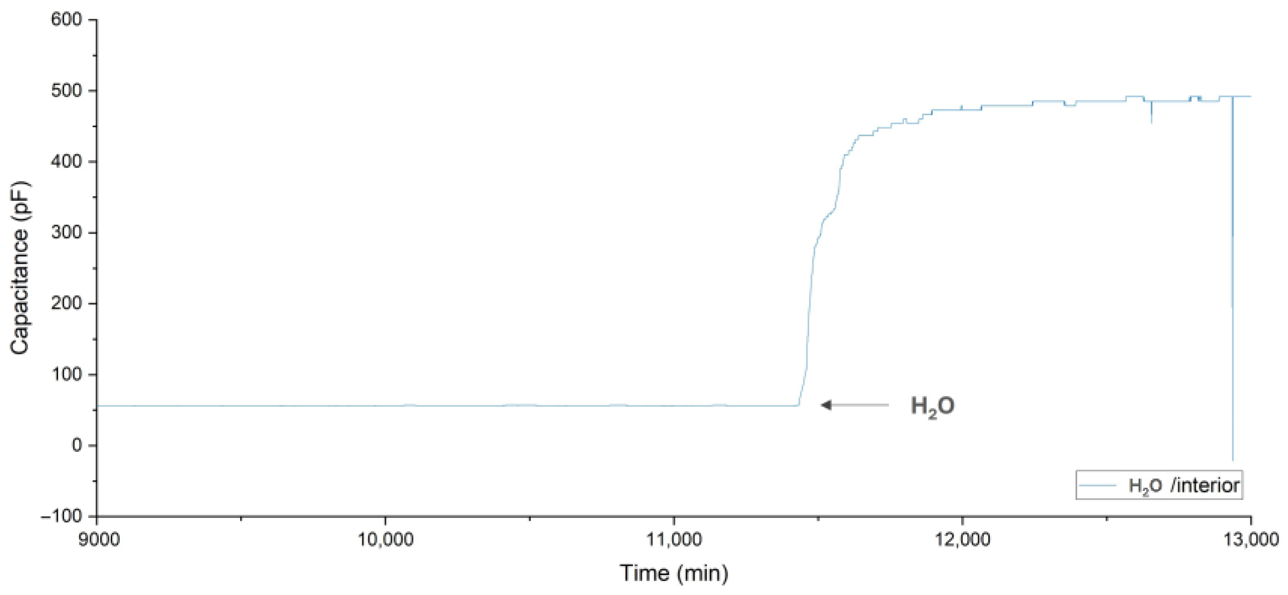
3.2.1. Temperature and Water Detection Measurements during Hygrothermal Cycles

The temperature measurements presented in Figure 16 were performed using the new monitoring system and gathered using the gateway. They exhibit the expected variations. This figure shows the results for the sensor positioned at M2 (positions according to Figure 6), belonging to the cold LSF type. The maximum temperature was recorded at the sensor close to the exterior side and reached approximately 60 °C when the climatic chamber was set to 70 °C. This was the behavior for 80 cycles, and both the climatic chamber and printed sensors exhibited a good replicability during this stage of the test. The high rate of temperature variation was well-registered, with the temperature drop during the one-hour rain simulation being particularly interesting. Later, the temperature sensors also correctly recorded the temperature change during the freeze/thaw cycles (a zoom of these results is shown in Figure 17). Inside the wall, the temperature varies between around 45 °C and −8 °C, which was expected when the climatic chamber was set to be between 50 °C and −20 °C. The measurements are also consistent with the pattern of the reference sensors (SHT).
A comparison between the hybrid and the cold LSF construction types can also be assessed from the measurements collected during the test. Figure 18 and Figure 19 summarize the maximum and minimum temperatures registered during the heat/rain and freeze/thaw cycles, respectively.
Evaluation of the above charts allows us to conclude that hybrid construction improves the thermal effects in the structure. Specifically, when considering the maximum temperatures achieved during the heat/rain cycles, the values recorded by the sensors (both interior and exterior) were considerably lower for modules M6 and M8 (hybrid construction) when compared to the ones from modules M2 and M11 (cold frame construction). In particular, the temperature differences were as high as 30 °C. In contrast, for the minimum temperatures of the freeze/thaw cycles, a higher temperature was noted in the ETICS area. For example, the exterior temperature registered for module M6 was 15 °C warmer than the equivalent for M11. Therefore, these results demonstrate the positive influence of the ETICS system in the attenuation of thermal bridges in LSF profiles.
In addition to the thermal analysis, the operation of the printed water detection sensors was also assessed. The occurrence of infiltrations in the test specimen during the heat/rain cycles meant that the presence of water on the inside of the LSF structure was detected by the sensors of the modules M1 and M7 (installed on the lower part of the profile and consequently more exposed to water penetration in the interface between the wall and the supported frame, which is rising by capillarity). The respective capacitive responses of these sensors are presented in Figure 20 and Figure 21.
As mentioned previously, the presence of water is identified because of the increase of the capacitive signal when referred to its base signal. From a further visual inspection of the test specimen, the infiltration of water in the wall was confirmed in the area of the abovementioned modules. No occurrence was identified for the M3 and M5 modules, with the integrity of the wall being subsequently confirmed.

3.2.2. Temperature Measurements during Solar Radiation Cycles

Figure 22 presents the results for the accelerated cycles under solar radiation. A comparison between surface temperatures with and without radiation is made on the hybrid LSF side. The maximum temperature is approximately 5 °C higher on the external surface affected by radiation, even for the same temperature inside the climatic chamber. This demonstrates that solar radiation will increase the temperature stress put on the rendering system layers and may also affect the LSF profiles during the ageing cycles.

3.2.3. Determination of the Thermal Transmission Coefficient, U-Value

The determination of the U-value was carried out according to ISO 9869-1—Thermal insulation—Building elements—In situ measurements of thermal resistance and thermal transmittance [49]. The temperature and heat flux measurements, recorded for approximately 90 h of steady state conditions, are presented in Figure 23.
Applying Equation (1) (Section 2.5) to the values depicted in the graph in Figure 23, a U-value of 0.38 W/m2 K is obtained for the hybrid solution (result of the division between the sum of the heat flux values (solid black line) and the sum of the difference between the internal surface temperature (dashed red line) and the external surface temperature (solid red line)), with a standard deviation of 0.02 W/m2·K. For the cold solution, the obtained U-value was 1.38 W/(m2·K) (result of the division between the sum of the heat flux values (dashed green line) and the sum of the difference between the internal surface temperature (dashed blue line) and the external surface temperature (solid blue line)), with a standard deviation of 0.03 W/(m2·K).
These results also highlight the relevance of the ETICS solution for the thermal performance of the LSF wall, minimizing the impact of LSF thermal bridges and avoiding the heat flux variations due to the internal surface temperature fluctuations (non-controlled environment).

3.2.4. Visual Inspection

Visual inspection of the test specimen after the hygrothermal cycles showed that the innovative LSF profile did not present dimensional variations and that no cracks were found in the rendering system. Figure 24 presents images of the visual inspection performed on the test specimen after the hygrothermal cycles.
After dismantling the test specimen, the proper condition of the LSF profiles and the presence of water (wet mineral wool) in the lower part of the wall were confirmed. The water had already been detected by the sensors during the ageing test. The infiltration occurred because the point where the base of the wall and the support metal frame met was not watertight.

3.2.5. Thermographic Analysis

A thermographic study was also carried out during the heating period of the heat/rain cycles and during the freezing period of the freeze/thaw cycles. Figure 25 presents the thermograms during the heating period of the heat/rain cycles and Figure 26 presents the thermograms during the freezing period of the freeze/thaw cycles. The side on which the images were taken is the inner side (non-controlled conditions).
The thermograms presented in Figure 25 and Figure 26 highlight the lower thermal performance in the zone of the LSF profiles (thermal bridge zone). In the thermograms obtained during the heating cycles the profile zone has a higher temperature than the zone without the profile. This is observed in the two constructive solutions assessed. However, the profile zones of the cold frame solution reveal higher heat transfer rates. On the other hand, the thermograms obtained during the freezing cycles show that the profiles exhibited lower temperatures than the current zone. The thermograms also show that the zone around the window is an area that allows greater heat exchange, as expected. An important linear thermal bridge in the window-wall junction explains this behavior.
From the thermograms, it should also be noted that water is present in the bottom of the test specimen. The bottom lower temperatures disclose the presence of water. When the moisture increases, the thermal transmittance rises. Moreover, the drop in the surface temperature may also be due to surface evaporation. The presence of water in the bottom of the test specimen, as mentioned in Section 3.2.1, was also identified by the sensors placed in that particular area (sensor M1 and M7). Consequently, the findings from the thermographic study serve to confirm the results obtained from sensor readings.

4. Discussion

4.1. Main Findings

The results showed that the innovative profile proved to be resistant to hygrothermal cycles with and without solar radiation. The profile is perfectly adjustable to current LSF constructive solutions. The faster installation of the new LSF profile was established during the construction of the real-scale test specimen. The monitoring system developed is efficient and works correctly. It was also demonstrated that a cold frame solution leads to greater heat loss and greater temperature variations, which means that this constructive solution has a lower hygrothermal performance and is therefore more vulnerable to internal mold growth and to superficial and interstitial condensation. This conclusion is in line with other studies. Zhan et al. [43] stated that the exterior cladding was crucial not only for aesthetic design purposes but also for controlling the level and duration of heat and humidity exposure. Santos et al. [46] verified, through infrared thermography images, that in a LSF wall with ETICS, the location of the vertical steel studs is not clearly visible, unlike walls without ETICS. These authors also concluded that the application of an ETICS system leads to an approximation of the U-value between the profiles zone and the U-value of the zone with metallic profiles. In another study, based on the temperature measurements they conducted, Atsonios et al. [1] observed that in the cold solution, the profiles led to a greater surface temperature disturbance (more than 3 °C) compared to the hybrid solution they studied (1.2 °C). These conclusions demonstrate that ETICS has a high efficacy in mitigating steel frame thermal bridging.
An additional concern identified by the authors of this study relies on the fact that the geometry of the innovative profile’s cross-section is larger than that of a conventional LSF profile. This leads to a higher impact of thermal bridges. Consequently, an additional study was conducted to determine the resulting impact of the increased cross-sectional area. To achieve this, using the “Guarded Hot Plate Single-specimen Apparatus λ-Meter EP 500” and considering the steady-state heat conduction phenomenon, the thermal resistance of the innovative profile embedded in EPS (Expanded Polystyrene) and a conventional profile, also embedded in EPS, was determined, as documented by the images in Figure 27. The tests for determining thermal conductivity were carried out at an average temperature of 23 °C with a 20 °C temperature difference between the plates of the equipment.
The results obtained are presented in Table 3.
The results show that due to the larger cross-section of the innovative profile, the thermal resistance of this assembly is lower (a difference of 0.24 m2·°C/W).

4.2. Limitations and Advantages

Despite the significant findings, some limitations should be considered in interpreting the results. The main limitations of the present study include the need for conducting a similar study with a large test specimen constructed using current LSF profiles to compare the results. Furthermore, conducting a comparative study of economic feasibility would enhance the comprehensiveness and robustness of this work. For that, manufacturers need to define the real cost of the profiles. From the perspective of hygrothermal assessment, the test specimen is an isolated 2D element, it is essential to evaluate connections with roofing, flooring, and other specificities of a building, such as corners, balconies, or connection to the ground slab layer. Moreover, as the procedure used for hygrothermal cycles under solar radiation is innovative, further studies are needed to increase confidence in the obtained results. Therefore, these limitations present opportunities for future work to enhance the quality and confidence of this study.
Regarding the advantages, the current study has developed and implemented a novel laboratory ageing method that enables a more comprehensive and realistic assessment of hygrothermal performance. An innovative monitoring system was implemented and validated, allowing for the evaluation of the hygrothermal performance of an LSF structure throughout its service life. This monitoring system will help prevent building pathologies related to water ingress and interstitial condensation. It is also worth mentioning that the adopted methodology follows the ideas mentioned in other studies, such as [22,42], where it is stated that: the light steel frame walls require more complex and detailed analysis than ones necessary for reinforced concrete and masonry constructions; the heterogeneity of materials and the high frequency of metal studs may lead to an overestimation of thermal resistance using available technical data from manufacturers; and there is a need for large scale case studies for proper assessment. Additionally, the results of temperature and heat flow measurements can be used for the validation of numerical models. Overall, this study, in addition to validating an innovative LSF profile incorporating printed sensors, could establish a foundation for more comprehensive assessments and enhancements of the hygrothermal performance, durability, and sustainability of LSF buildings.

5. Conclusions

The main goal of this study was to evaluate the hygrothermal behavior of an innovative LSF profile incorporating a monitoring system developed under an innovation action with industry (SMARTLSF project). For this purpose, an experimental procedure was carried out on a large-scale specimen placed in a climatic chamber. The test specimen was subjected to standard ageing cycles according to EAD 040083-00-0404 [47] and to innovative accelerated ageing cycles under solar radiation simulation. The temperature and water detection printed sensors were verified first using small-scale specimens. In addition to this new monitoring system incorporated in the structure, the test specimen was instrumented with thermocouples and heat flux sensors in the LSF profile areas to assess the influence of the solar radiation and to determine the thermal transmittance (U-value) of the LSF wall.
First, the experimental procedure considered a steady-state boundary condition to allow the determination of the thermal transmittance. Next, the experimental procedure followed standard hygrothermal cycles (the above-mentioned ageing cycles), including 80 heat/rain and five freeze/thaw cycles. Finally, innovative ageing cycles with solar radiation simulation were performed.
The main conclusions of this work are as follows:
  • The sensors used in the integrated monitoring system proved to be efficient. The results show that the measurements with the printed sensors followed the expected variation of each test cycle; they were also consistent with the pattern of the reference sensors (SHT). Furthermore, the monitoring system was capable of evaluating the thermal gradients and the presence of water infiltration that occurred during the tests.
  • The innovative profile developed proved to be stable during the hygrothermal cycles. No failures or defects such as deformations, warping, or distortions that could compromise the hygrothermal behavior of the system occurred. Thus, the stability of the innovative profiles is considered validated from the point of view of hygrothermal behavior. Wind resistance tests were performed for a maximum pressure of 3000 Pa, as well as impact tests of 10 J (not presented in this paper), and the wall kept its structural integrity.
  • The hybrid LSF constructive solution using an external thermal insulation composite system applied to the OSB layer leads to more stable temperatures on the inner surface. On the other hand, this constructive solution resulted in a higher external surface temperature than the solution without ETICS, leading to higher levels of stress for the rendering system.
  • The results during the accelerated ageing cycles under solar radiation simulation show that the incidence of solar radiation may lead to surface temperatures 5 °C higher compared to the surface without the incidence of direct solar radiation, even using a light color.
  • The thermographic study and the in situ determination of the U-value reveal that the use of an ETICS system is essential to minimize the effect of thermal bridges caused by LSF profiles. The U-value of the hybrid constructive solution is, as expected, lower than the cold constructive solution. Moreover, the thermograms showed higher heat transfer rates in the profile zone of the cold constructive solution than the profile zone of the hybrid constructive solution.
  • Additionally, the thermographic study confirmed the presence of water in the bottom of the test specimen. This indicates that the wall became wet due to capillary action, as indicated by the readings from the printed sensors installed in this area of the test specimen. Consequently, the evidence obtained from the thermographic study supports and validates the results obtained from the sensors developed.
  • One of the weaknesses of the wall is the singularities associated with the window installation. The thermograms clearly show the thermal bridges created in the wall-window junctions. The window in the LSF was installed normally, with no difficulties arising in its execution. No water penetration was registered. However, it is highly recommended to cover the window frame with insulation or to fit the window with the plane of the wall insulation in order to minimize the installation thermal bridges.

Author Contributions

Conceptualization, R.J. and N.S.; methodology, R.J., M.G. and N.S; investigation, R.J. and M.G.; resources, M.G. and C.F. (Cristina Furtado); monitoring system, C.F. (Cristina Furtado), K.R. and C.F. (César Ferreira); validation, N.S.; data curation, R.J., M.G., C.F. (Cristina Furtado), K.R. and C.F. (César Ferreira); writing—original draft preparation, R.J and C.F. (Cristina Furtado); writing—review and editing, R.J., M.G., K.R. and N.S.; supervision, N.S. All authors have read and agreed to the published version of the manuscript.

Funding

This research was funded by the FCT Portuguese Foundation for Science and Technology (UIDB/04625/2020) from the research unit CERIS and by the SMARTLSF project (POCI-01-0247-FEDER-039955) co-financed by the European Regional Development Fund (FEDER).

Data Availability Statement

The data presented in this study are available on request from the corresponding author.

Acknowledgments

The authors gratefully acknowledge the support of CERIS, Itecons and CeNTI.

Conflicts of Interest

The authors declare no conflict of interest. The funders had no role in the design of the study; in the collection, analyses, or interpretation of data; in the writing of the manuscript; or in the decision to publish the results.

References

  1. Atsonios, I.A.; Mandilaras, I.D.; Kontogeorgos, D.A.; Founti, M.A. Two new methods for the in-situ measurement of the overall thermal transmittance of cold frame lightweight steel-framed walls. Energy Build. 2018, 170, 183–194. [Google Scholar] [CrossRef]
  2. Soliman, A.; Hafeez, G.; Erkmen, E.; Ganesan, R.; Ouf, M.; Hammad, A.; Eicker, U.; Moselhi, O. Innovative construction material technologies for sustainable and resilient civil infrastructure. Mater. Today Proc. 2022, 60, 365–372. [Google Scholar] [CrossRef]
  3. Zhou, J.; Li, Y.; Ren, D. Quantitative study on external benefits of prefabricated buildings: From perspectives of economy, environment, and society. Sustain. Cities Soc. 2022, 86, 104132. [Google Scholar] [CrossRef]
  4. Tavares, V.; Soares, N.; Raposo, N.; Marques, P.; Freire, F. Prefabricated versus conventional construction: Comparing life-cycle impacts of alternative structural materials. J. Build. Eng. 2021, 41, 102705. [Google Scholar] [CrossRef]
  5. Wang, H.; Zhang, Y.; Gao, W.; Kuroki, S. Life cycle environmental and cost performance of prefabricated buildings. Sustainability 2020, 12, 2609. [Google Scholar] [CrossRef]
  6. Chen, Y.; Zhu, D.; Tian, Z.; Guo, Q. Factors influencing construction time performance of prefabricated house building: A multi-case study. Habitat Int. 2023, 131, 102731. [Google Scholar] [CrossRef]
  7. Navaratnam, S.; Satheeskumar, A.; Zhang, G.; Nguyen, K.; Venkatesan, S.; Poologanathan, K. The challenges confronting the growth of sustainable prefabricated building construction in Australia: Construction industry views. J. Build. Eng. 2022, 48, 103935. [Google Scholar] [CrossRef]
  8. Tavares, V.; Gregory, J.; Kirchain, R.; Freire, F. What is the potential for prefabricated buildings to decrease costs and contribute to meeting EU environmental targets? Build. Environ. 2021, 206, 108382. [Google Scholar] [CrossRef]
  9. Thai, H.T.; Ngo, T.; Uy, B. A review on modular construction for high-rise buildings. Structures 2020, 28, 1265–1290. [Google Scholar] [CrossRef]
  10. Hong, J.; Shen, G.Q.; Li, Z.; Zhang, B.; Zhang, W. Barriers to promoting prefabricated construction in China: A cost–benefit analysis. J. Clean. Prod. 2018, 172, 649–660. [Google Scholar] [CrossRef]
  11. Pan, W.; Zhang, Z. Benchmarking the sustainability of concrete and steel modular construction for buildings in urban development. Sustain. Cities Soc. 2023, 90, 104400. [Google Scholar] [CrossRef]
  12. Lim, Y.W.; Ling, P.C.H.; Tan, C.S.; Chong, H.Y.; Thurairajah, A. Planning and coordination of modular construction. Autom. Constr. 2022, 141, 104455. [Google Scholar] [CrossRef]
  13. Roque, E.; Vicente, R.; Almeida, R.M.S.F.; Ferreira, V.M. Energy consumption in intermittently heated residential buildings: Light Steel Framing vs hollow brick masonry constructive system. J. Build. Eng. 2021, 43, 103024. [Google Scholar] [CrossRef]
  14. Aye, L.; Ngo, T.; Crawford, R.H.; Gammampila, R.; Mendis, P. Life cycle greenhouse gas emissions and energy analysis of prefabricated reusable building modules. Energy Build. 2012, 47, 159–168. [Google Scholar] [CrossRef]
  15. Cao, X.; Li, X.; Zhu, Y.; Zhang, Z. A comparative study of environmental performance between prefabricated and traditional residential buildings in China. J. Clean. Prod. 2015, 109, 131–143. [Google Scholar] [CrossRef]
  16. Soares, N.; Santos, P.; Gervásio, H.; Costa, J.J.; Simões da Silva, L. Energy efficiency and thermal performance of lightweight steel-framed (LSF) construction: A review. Renew. Sustain. Energy Rev. 2017, 78, 194–209. [Google Scholar] [CrossRef]
  17. Roque, E.; Santos, P. The effectiveness of thermal insulation in lightweight steel-framedwalls with respect to its position. Buildings 2017, 7, 13. [Google Scholar] [CrossRef]
  18. Perera, D.; Poologanathan, K.; Gillie, M.; Gatheeshgar, P.; Sherlock, P.; Nanayakkara, S.M.A.; Konthesingha, K.M.C. Fire performance of cold, warm and hybrid LSF wall panels using numerical studies. Thin-Walled Struct. 2020, 157, 107109. [Google Scholar] [CrossRef]
  19. Zhan, Q.; Xiao, Y.; Musso, F.; Zhang, L. Assessing the hygrothermal performance of typical lightweight steel-framed wall assemblies in hot-humid climate regions by monitoring and numerical analysis. Build. Environ. 2021, 188, 107512. [Google Scholar] [CrossRef]
  20. Zhan, Q.; Pungercar, V.; Musso, F.; Ni, H.; Xiao, Y. Hygrothermal investigation of lightweight steel-framed wall assemblies in hot-humid climates: Measurement and simulation validation. J. Build. Eng. 2021, 42, 103044. [Google Scholar] [CrossRef]
  21. Santos, P.; Mateus, D. Experimental assessment of thermal break strips performance in load-bearing and non-load-bearing LSF walls. J. Build. Eng. 2020, 32, 101693. [Google Scholar] [CrossRef]
  22. De Angelis, E.; Serra, E. Light steel-frame walls: Thermal insulation performances and thermal bridges. Energy Procedia 2014, 45, 362–371. [Google Scholar] [CrossRef]
  23. Perera, D.; Upasiri, I.R.; Poologanathan, K.; Gatheeshgar, P.; Sherlock, P.; Hewavitharana, T.; Suntharalingam, T. Energy performance of fire rated LSF walls under UK climate conditions. J. Build. Eng. 2021, 44, 103293. [Google Scholar] [CrossRef]
  24. Brambilla, A.; Sangiorgio, A. Mould growth in energy efficient buildings: Causes, health implications and strategies to mitigate the risk. Renew. Sustain. Energy Rev. 2020, 132, 110093. [Google Scholar] [CrossRef]
  25. Gradeci, K.; Labonnote, N.; Time, B.; Köhler, J. Mould growth criteria and design avoidance approaches in wood-based materials—A systematic review. Constr. Build. Mater. 2017, 150, 77–88. [Google Scholar] [CrossRef]
  26. Orlik-Kozdoń, B. Microclimate conditions in rooms: Their impact on mold development in buildings. Energies 2020, 13, 4492. [Google Scholar] [CrossRef]
  27. Hancock, G.J. Cold-formed steel structures. J. Constr. Steel Res. 2003, 59, 473–487. [Google Scholar] [CrossRef]
  28. Gatheeshgar, P.; Parker, S.; Askew, K.; Poologanathan, K.; Navaratnam, S.; McIntosh, A.; Widdowfield Small, D. Flexural behaviour and design of modular construction optimised beams. Structures 2021, 32, 1048–1068. [Google Scholar] [CrossRef]
  29. Hadjipantelis, N.; Gardner, L.; Wadee, M.A. Prestressed cold-formed steel beams: Concept and mechanical behaviour. Eng. Struct. 2018, 172, 1057–1072. [Google Scholar] [CrossRef]
  30. Hadjipantelis, N.; Gardner, L.; Wadee, M.A. Finite-Element Modeling of Prestressed Cold-Formed Steel Beams. J. Struct. Eng. 2019, 145, 04019100. [Google Scholar] [CrossRef]
  31. Ye, J.; Hajirasouliha, I.; Becque, J.; Pilakoutas, K. Development of more efficient cold-formed steel channel sections in bending. Thin-Walled Struct. 2016, 101, 1–13. [Google Scholar] [CrossRef]
  32. Gatheeshgar, P.; Poologanathan, K.; Gunalan, S.; Nagaratnam, B.; Tsavdaridis, K.D.; Ye, J. Structural behaviour of optimized cold-formed steel beams. Steel Constr. 2020, 13, 294–304. [Google Scholar] [CrossRef]
  33. Keerthan, P.; Mahendran, M. Improved shear design rules of cold-formed steel beams. Eng. Struct. 2015, 99, 603–615. [Google Scholar] [CrossRef]
  34. Keerthan, P.; Mahendran, M.; Hughes, D. Numerical studies and design of hollow flange channel beams subject to combined bending and shear actions. Eng. Struct. 2014, 75, 197–212. [Google Scholar] [CrossRef]
  35. Perera, N.; Mahendran, M. Finite element analysis and design for section moment capacities of hollow flange steel plate girders. Thin-Walled Struct. 2019, 135, 356–375. [Google Scholar] [CrossRef]
  36. Poologanathan, K.; Mahen, M. Numerical Modeling of LiteSteel Beams Subject to Shear. J. Struct. Eng. 2011, 137, 1428–1439. [Google Scholar] [CrossRef]
  37. Anapayan, T.; Mahendran, M.; Mahaarachchi, D. Section moment capacity tests of LiteSteel beams. Thin-Walled Struct. 2011, 49, 502–512. [Google Scholar] [CrossRef]
  38. Siahaan, R.; Keerthan, P.; Mahendran, M. Finite element modeling of rivet fastened rectangular hollow flange channel beams subject to local buckling. Eng. Struct. 2016, 126, 311–327. [Google Scholar] [CrossRef]
  39. Steau, E.; Mahendran, M.; Keerthan, P. Web crippling tests of Rivet Fastened Rectangular Hollow Flange Channel Beams under Two Flange Load Cases. Thin-Walled Struct. 2015, 95, 262–275. [Google Scholar] [CrossRef]
  40. Roy, K.; Ting, T.C.H.; Lau, H.H.; Lim, J.B.P. Nonlinear behaviour of back-to-back gapped built-up cold-formed steel channel sections under compression. J. Constr. Steel Res. 2018, 147, 257–276. [Google Scholar] [CrossRef]
  41. Roy, K.; Lau, H.H.; Ting, T.C.H.; Chen, B.; Lim, J.B.P. Flexural capacity of gapped built-up cold-formed steel channel sections including web stiffeners. J. Constr. Steel Res. 2020, 172, 106154. [Google Scholar] [CrossRef]
  42. Abdelmageed, S.; Zayed, T. A study of literature in modular integrated construction—Critical review and future directions. J. Clean. Prod. 2020, 277, 124044. [Google Scholar] [CrossRef]
  43. Zhan, Q.; Xiao, Y.; Zhang, L.; Lin, Z.; Zou, Y.; Liao, W. Hygrothermal performance optimization of lightweight steel-framed wall assemblies in hot–humid regions using orthogonal experimental design and a validated simulation model. Build. Environ. 2023, 236, 110262. [Google Scholar] [CrossRef]
  44. Martins, J.A.; Gomes, C.M.; Fontanini, P.; Dornelles, K. Comparative analysis on thermal performance of MgO and fiber cement boards applied to light steel frame building systems. J. Build. Eng. 2019, 21, 312–316. [Google Scholar] [CrossRef]
  45. Friis, N.K.; Møller, E.B.; Lading, T. Hygrothermal assessment of external walls in Arctic climates: Field measurements and simulations of a test facility. Build. Environ. 2023, 238, 110347. [Google Scholar] [CrossRef]
  46. Santos, P.; Gonçalves, M.; Martins, C.; Soares, N.; Costa, J.J. Thermal transmittance of lightweight steel framed walls: Experimental versus numerical and analytical approaches. J. Build. Eng. 2019, 25, 100776. [Google Scholar] [CrossRef]
  47. EOTA External Thermal Insulation Composite Systems (Etics) with Renderings. 2019. Available online: https://www.eota.eu/download?file=/2014/14-04-0083/for%20ojeu/ead%20040083-00-0404_ojeu2020.pdf (accessed on 2 September 2022).
  48. (DIN) DIN 75220; Ageing of Automotive Components in Solar Simulation Units. Deutsches Institut fur Normung E.V.: Berlin, Germany, 1992.
  49. ISO 9869-1:2014; Thermal Insulation—Building Elements—Insitu Measurement of Thermal Resistance and Thermal Transmittance. Part 1: Heat Flow Meter Method. ISO: Geneva, Switzerland, 2014.
Figure 1. Types of LSF constructive solutions: (a) Cold solution; (b) Hybrid solution; (c) Warm solution. 1—Rendering system of the cold solution or ETICS of the hybrid solution and warm solution. 2—Exterior sheeting panel. 3—Cavity with or without thermal insulation. 4—Interior sheeting panel.
Buildings 13 02509 g001
Figure 2. Work methodology.
Buildings 13 02509 g002
Figure 3. The innovative profile developed under the SMARTLSF project with an extensibility feature.
Buildings 13 02509 g003
Figure 4. Screen-printing equipment available at CeNTI.
Buildings 13 02509 g004
Figure 5. Example of printed sensors produced for SMARTLSF project: (a) For temperature measurements; (b) For water detection.
Buildings 13 02509 g005
Figure 6. Test specimen: (a) Design of structure; (b) Construction of the test specimen; (c) Completed test specimen; (d) Test specimen in the climatic chamber.
Buildings 13 02509 g006aBuildings 13 02509 g006b
Figure 7. Schematic of the sensing modules’ distribution in the test specimen structure (external view).
Buildings 13 02509 g007
Figure 8. Test specimen structure from SMARTLSF project with integrated sensors (external view).
Buildings 13 02509 g008
Figure 9. Detailed images of the integration of three modules (identified as M1, M6, and M8 in Figure 8) in distinct positions.
Buildings 13 02509 g009
Figure 10. Placement of the thermocouples used to evaluate the ageing cycles under solar radiation: (a) Illustrative scheme with the position; (b) Placement of the sensors on the internal surface of the specimen; (c) Placement of the sensor on the external surface of the specimen.
Buildings 13 02509 g010
Figure 11. Placement of the thermocouples and heat flux sensors for the determination of the U-value: (a) Schematic; (b) Placement of the sensors on the external surface of the specimen and (c) Placement of the sensor on the internal surface of the specimen.
Buildings 13 02509 g011
Figure 12. Hygrothermal cycles apparatus: (a) Schematic of the climatic chamber FitoClima EC 50; (b) Test specimen installed in the climatic chamber.
Buildings 13 02509 g012
Figure 13. Solar radiation simulation system: (a) Solar lamps installed inside the chamber; (b) Test area with homogenous solar radiation incidence.
Buildings 13 02509 g013
Figure 14. Comparison of the characterization curves of three printed temperature sensors (as example), obtained with the laboratory climatic chamber.
Buildings 13 02509 g014
Figure 15. Comparison of the characterization curves from two examples of printed water detection sensors (inset: characterization setup).
Buildings 13 02509 g015
Figure 16. Temperatures registered by the sensors positioned at M2 during the hygrothermal cycles.
Buildings 13 02509 g016
Figure 17. Detailed view of the values registered by the temperature sensors from M2 during the freeze/thaw cycles.
Buildings 13 02509 g017
Figure 18. Overview of the maximum temperatures registered by the printed sensors (on external and internal sides) during heat/rain cycles.
Buildings 13 02509 g018
Figure 19. Overview of the minimum temperatures registered by the printed sensors (on external and internal sides) during freeze/thaw cycles.
Buildings 13 02509 g019
Figure 20. Capacitive response of the water detection sensor from M1 (detection after 26.3 h of testing).
Buildings 13 02509 g020
Figure 21. Capacitive response of the water detection sensor from M7 (detection after 190.6 h of testing).
Buildings 13 02509 g021
Figure 22. Temperature of the radiation cycles.
Buildings 13 02509 g022
Figure 23. Heat flux and temperature measured for the experimental determination of the U-value.
Buildings 13 02509 g023
Figure 24. Images of the visual inspection performed after the hygrothermal cycles.
Buildings 13 02509 g024
Figure 25. Thermograms during the heating period of the heat/rain cycles.
Buildings 13 02509 g025
Figure 26. Thermograms during the freezing period of the freeze/thaw cycles.
Buildings 13 02509 g026
Figure 27. (a) Testing of the specimen with the innovative LSF profile; (b) Testing of the specimen with the current LSF profile.
Buildings 13 02509 g027
Table 1. Components and its characteristics of the test specimen.
Cold Frame ConstructionHybrid Construction
ComponentThickness [mm]ComponentThickness [mm]
Gypsum board12.5Gypsum board12.5
Mineral wool150Mineral wool150
OSB12OSB12
Rendering system2ETICS system with 40 mm of EPS45
Table 2. Description of the equipment in the hygrothermal cycles resistance test.
Item (Model)DescriptionOutputIllustration
Climatic chamber (FitoClima 1000 EC 50)Climatic chamber with 14.5 m3 of conditioned volume. Temperature range
capacity of −20 to 150 °C (±5 °C) and humidity of 10–98% (±10%); Includes a water spraying system with 1 ± 0.1 L/(min·m2). This chamber is annually calibrated to accomplish the test procedure requirements.
Temperature control, relative
humidity control and water
spraying.
Buildings 13 02509 i001
Thermocouples (Type T thermocouples)Thermocouple with temperature range between −270 to 370 °C and
accuracy ± 1.0 °C or 0.75%
TemperatureBuildings 13 02509 i002
Heat flux sensor (FHF02SC-02)Heat flux sensor with a measurement range (−10 to +10) × 103 W/m2, a sensitivity of 5.5 × 10⁻⁶ V/(W/m2) and an uncertainty of calibration of 5%Heat flux (W/m2) and temperature (°C)Buildings 13 02509 i003
Data logger (Keysight 34970A)Data acquisition unitData filesBuildings 13 02509 i004
Infrared camera (FLIR T630sc)Infrared camera with accuracy: ±1 °C or ±1% at 25 °C; object temperature range: −40 °C to 150 °C; and resolution: 640 × 480 pixelsInfrared thermogramsBuildings 13 02509 i005
Solar radiation simulation system (BF SUN 2500 W)BF SUN 2500 W with a Osram HMI 2500 W lamp, and an Electronic Power Supply UnitSolar radiation: UV-C, UV-B, UV-A, visible and infrared radiationBuildings 13 02509 i006
Table 3. Thermal resistance of the LSF/EPS profile sets tested.
Test Specimenλ23 °C [W/(m·°C)]R23 °C [m2·°C/W]
Innovative LSF profile + EPS0.166841.271
Current LSF profile + EPS0.114871.511
Disclaimer/Publisher’s Note: The statements, opinions and data contained in all publications are solely those of the individual author(s) and contributor(s) and not of MDPI and/or the editor(s). MDPI and/or the editor(s) disclaim responsibility for any injury to people or property resulting from any ideas, methods, instructions or products referred to in the content.

