
Web-Crippling Capacity of High Performance Cold-Formed Lipped Steel Sections Subjected to Elevated Temperature

 , , and
Abstract
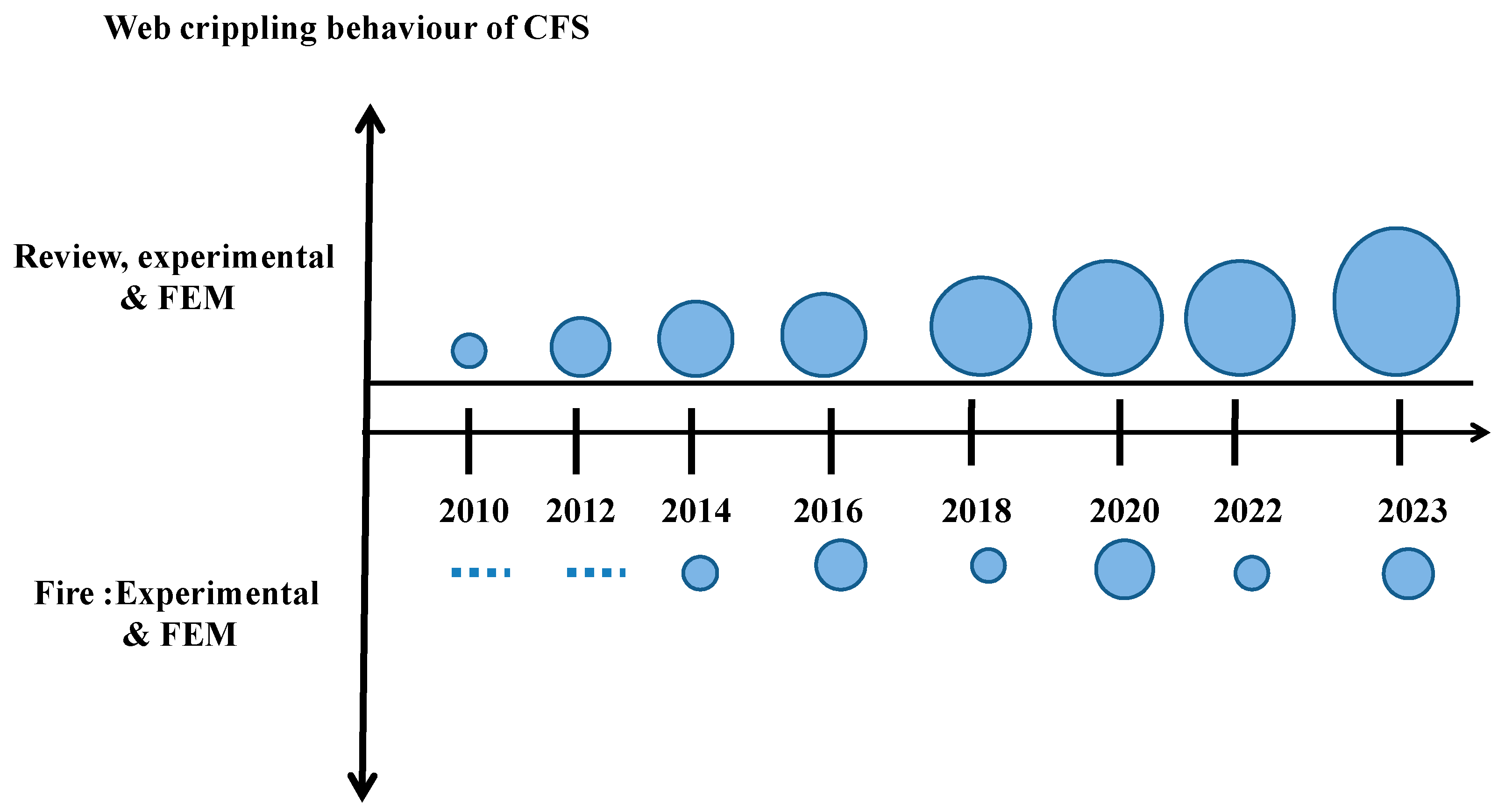
:1. Introduction
Research Significance
- To study the post-fire performance and web-crippling behaviour of high-performance CFS elements subjected to elevated temperature as per ISO 834 standard fire curve.
- Influence of web holes on web-crippling strength of high-performance CFS sections exposed to elevated temperature under ITF and ETF load cases.
- Investigations are conducted to examine the load-deflection behaviour, web-crippling strength, and failure modes of the CFS specimens heated and cooled by different mode.
- To understand the web-crippling response of high-performance CFS specimens, a FEM model was developed and validated with test results.
2. Experimental Investigation
2.1. Overview
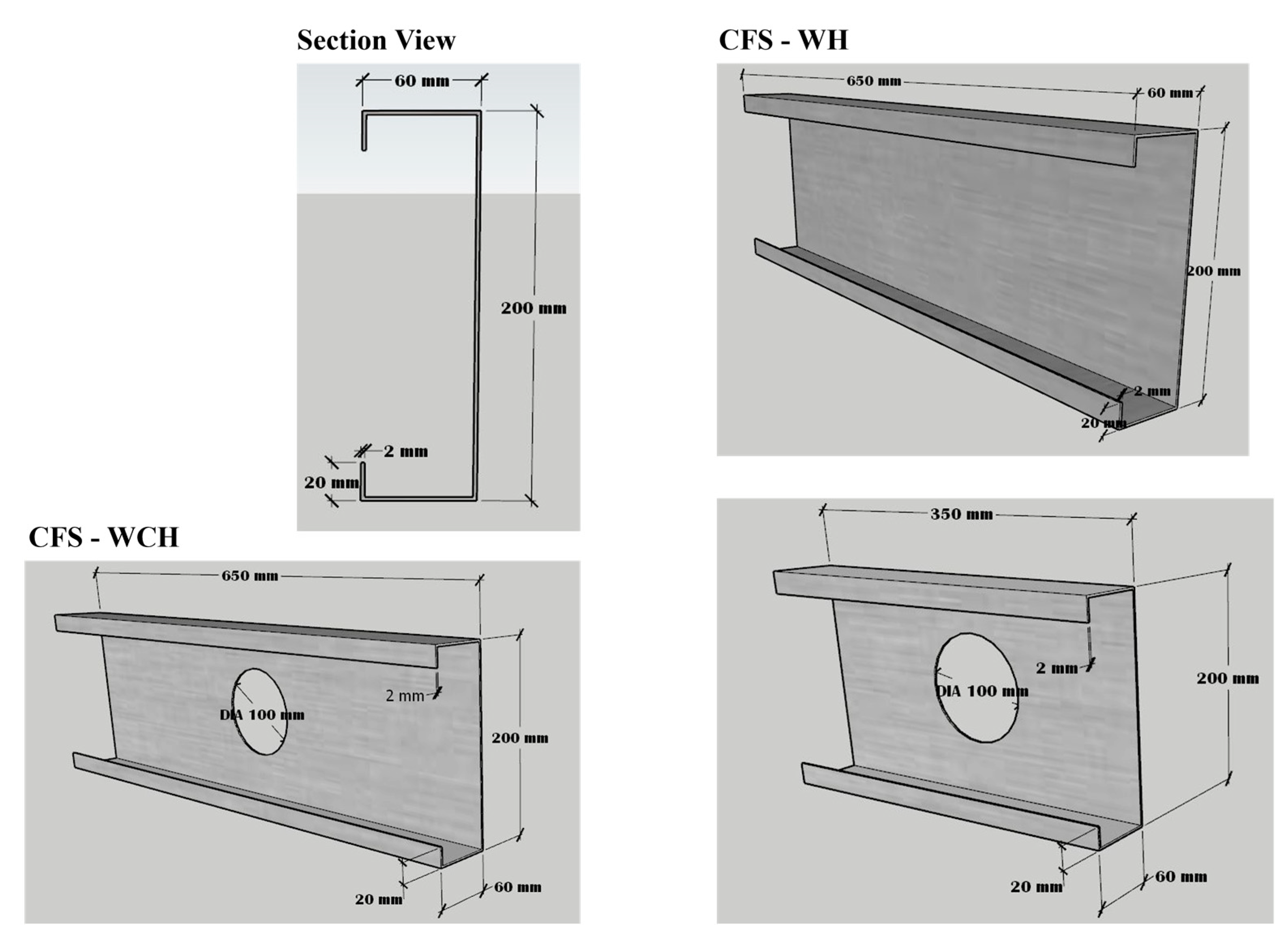
2.2. Specimen Details
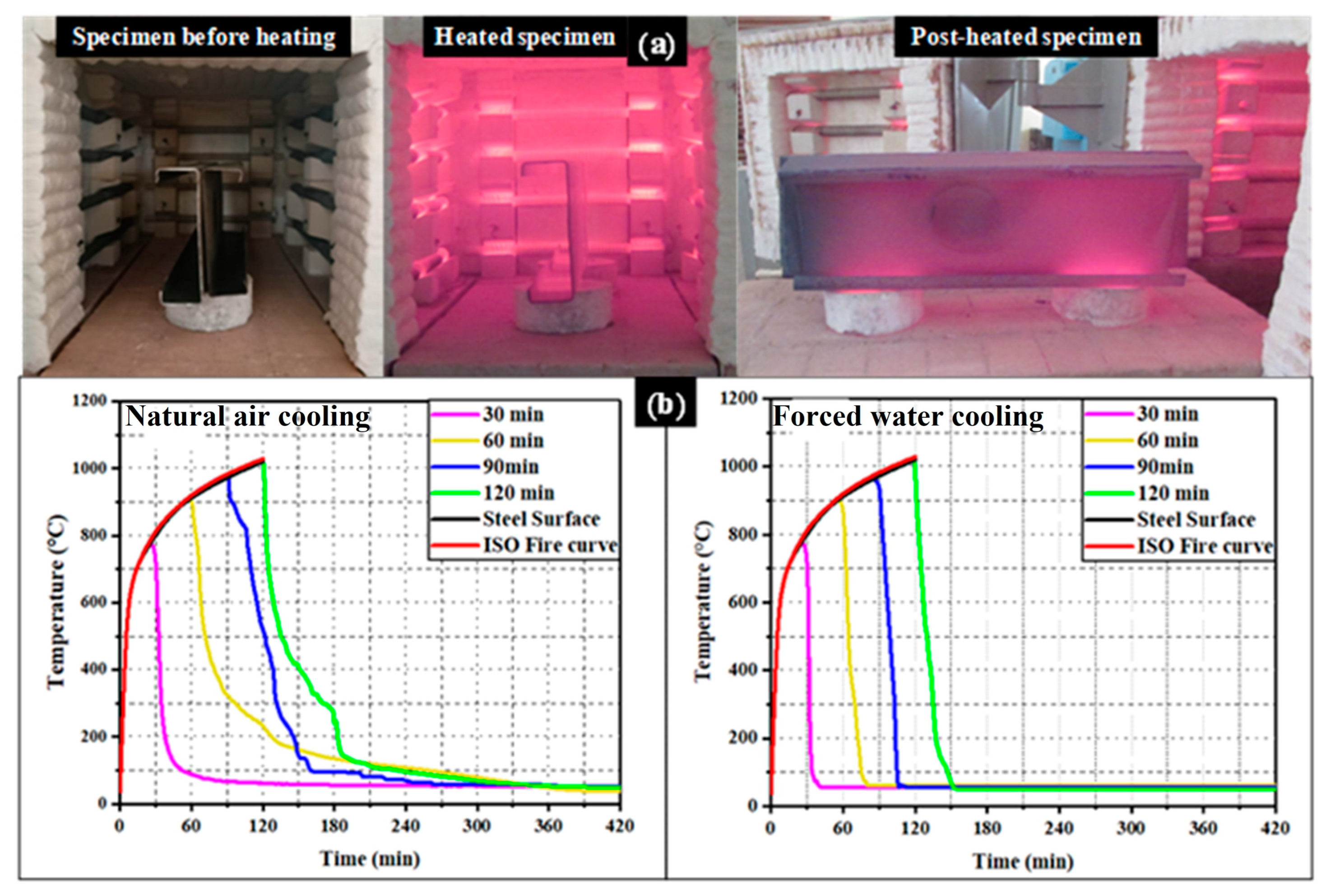
2.3. Elevated Temperature Test on CFS Sections (Heating and Cooling)
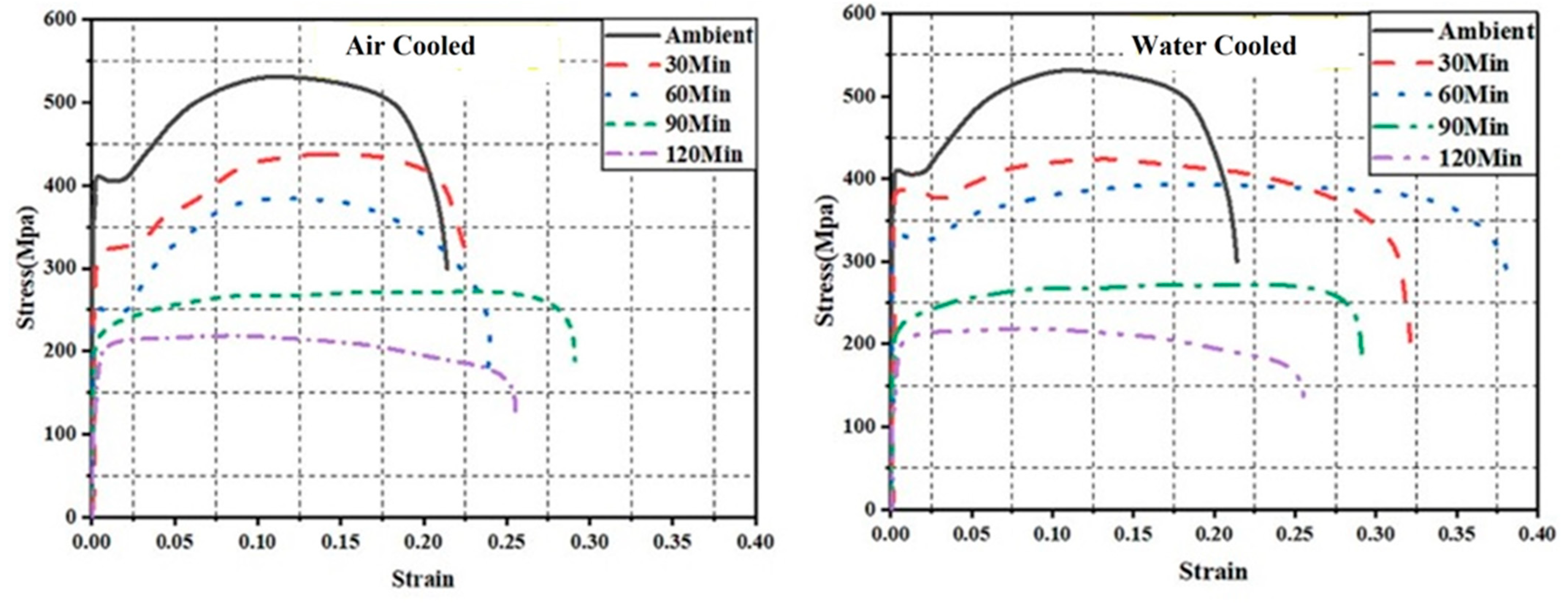
2.4. Material Properties
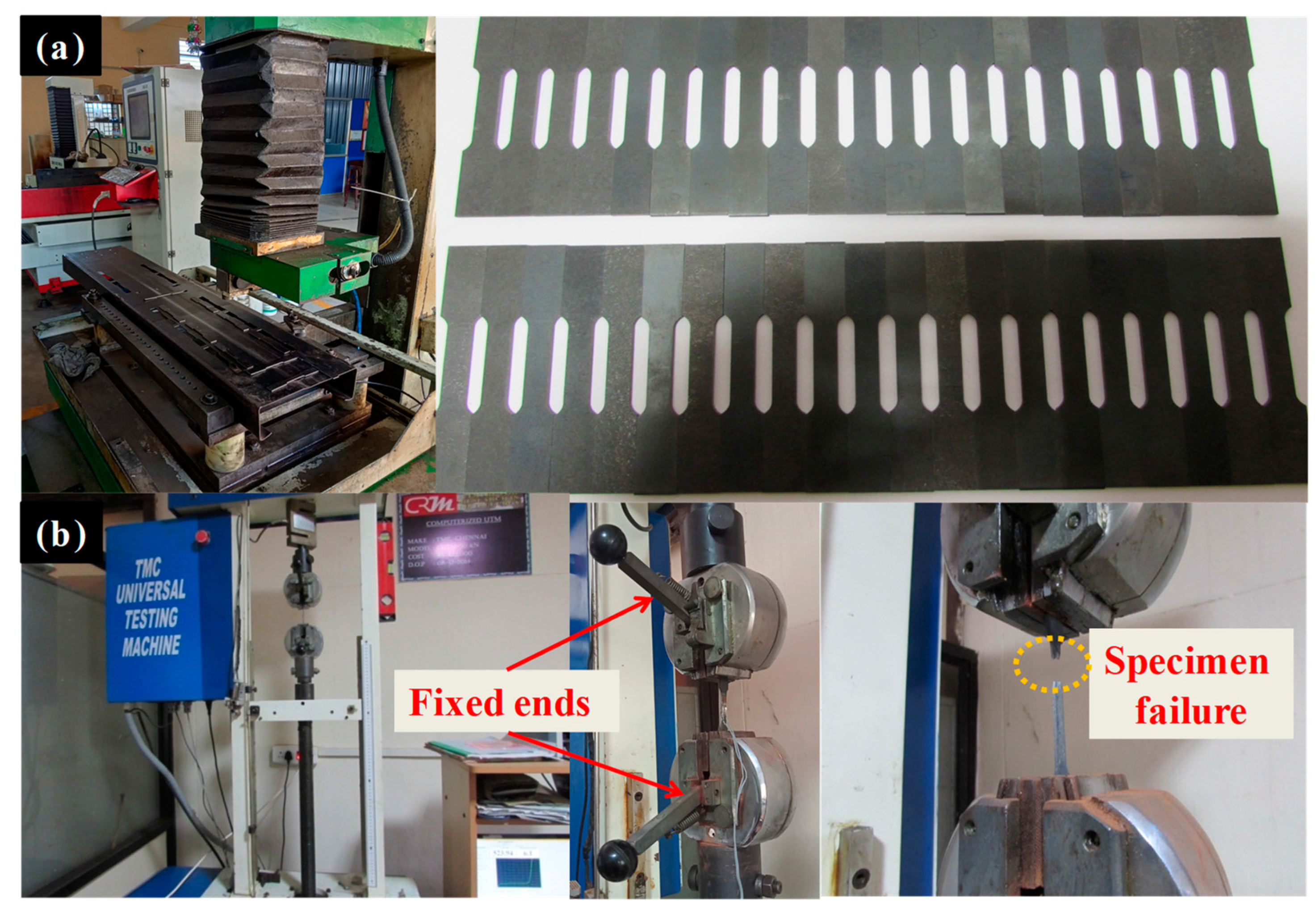
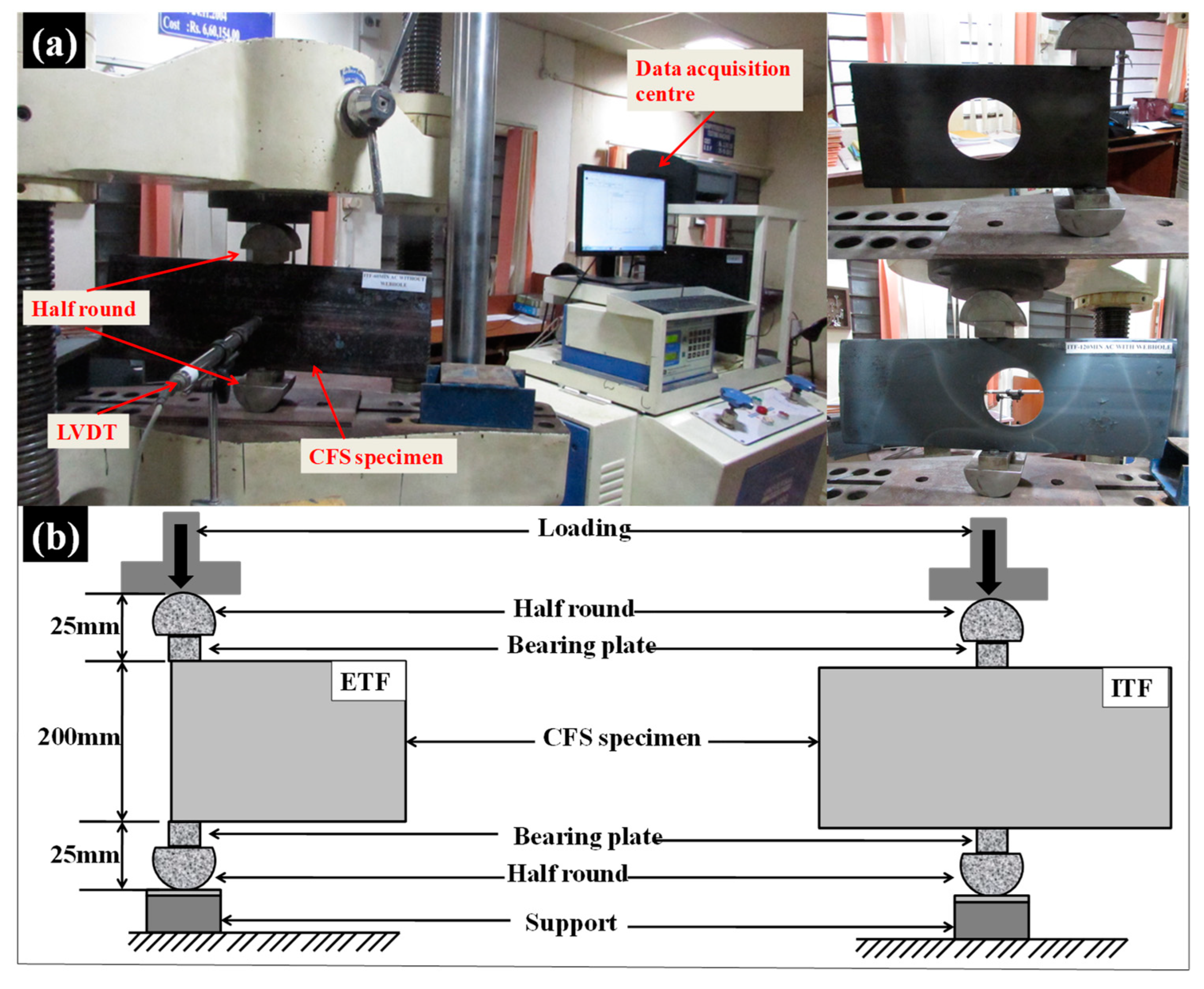
2.5. Experimental Setup
3. Results and Discussion
3.1. Load-Deflection Behaviour of CFS Beams
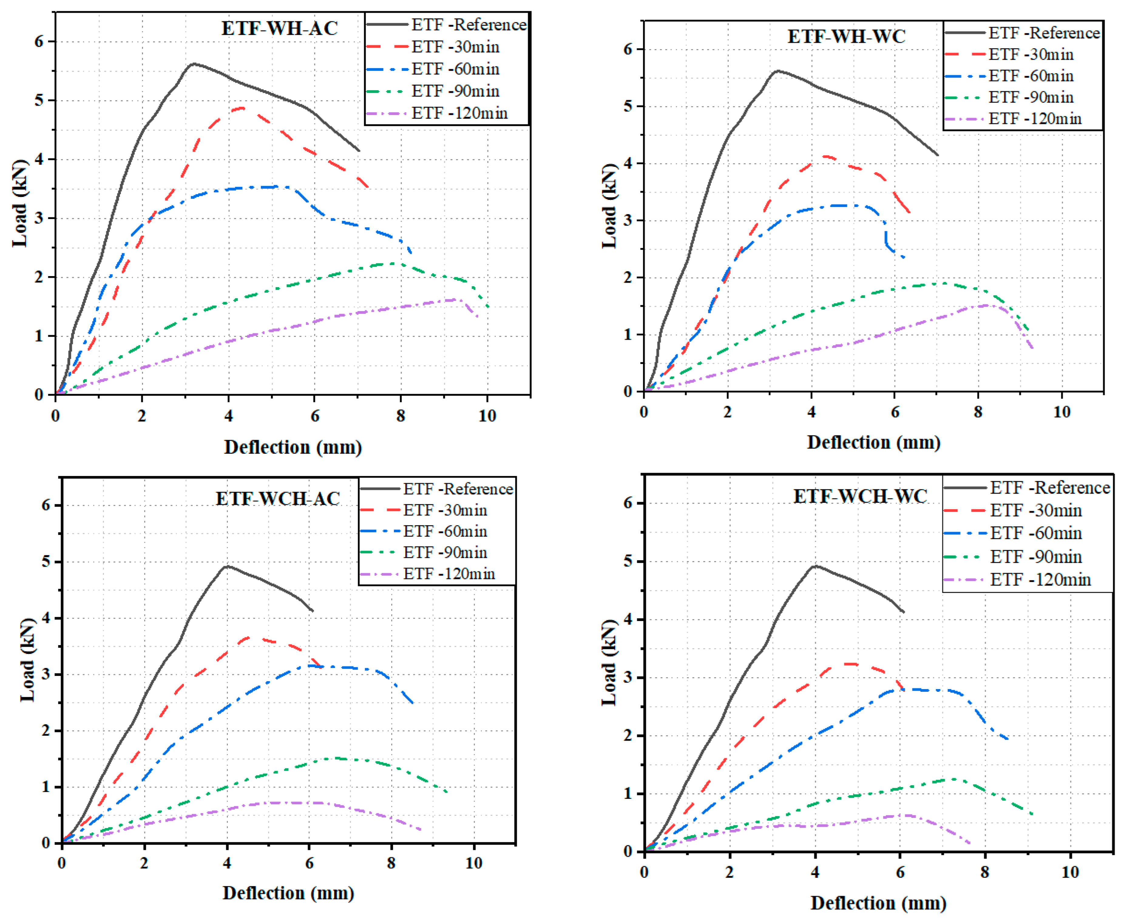
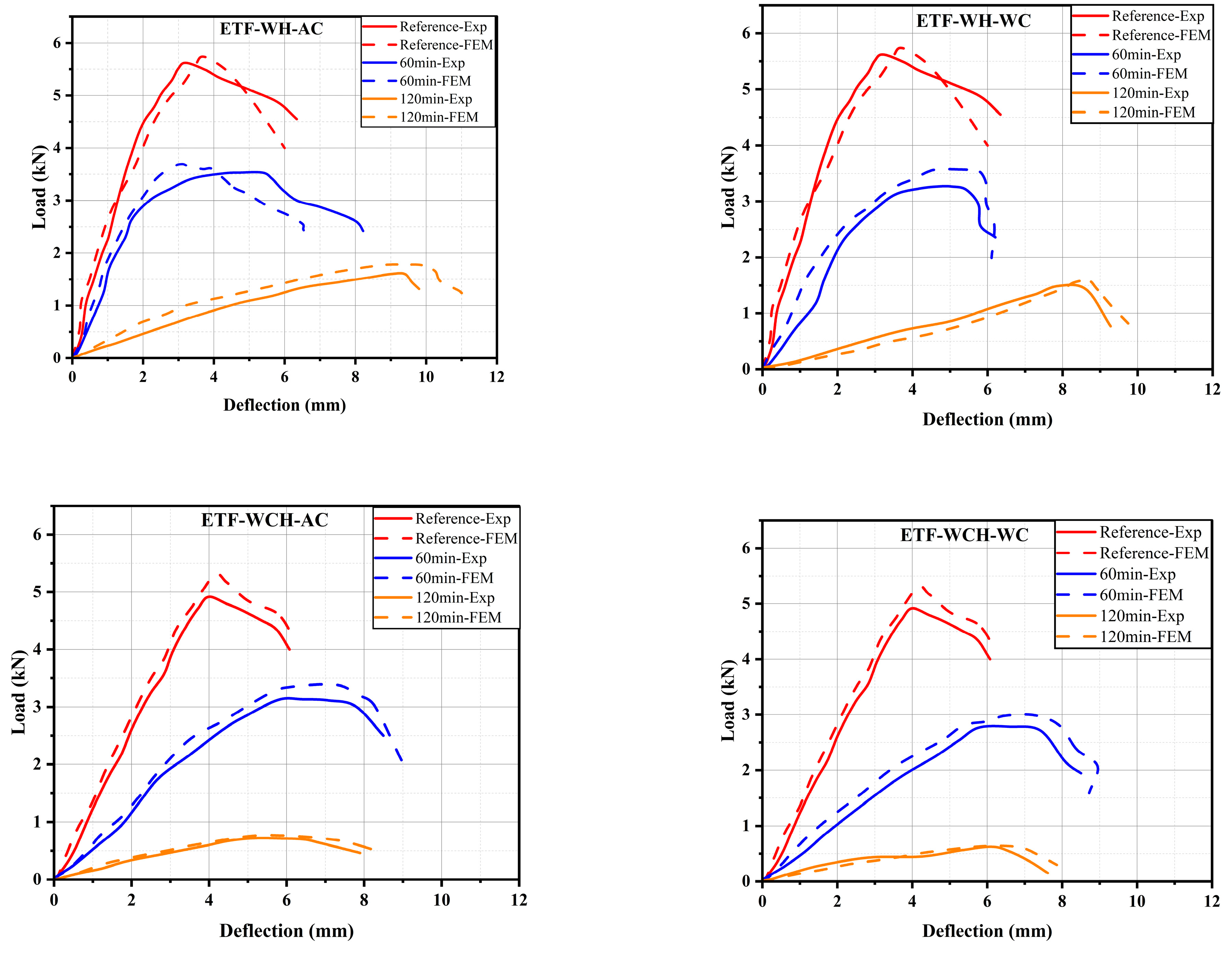
3.1.1. Load-Deflection Behaviour at ETF Condition
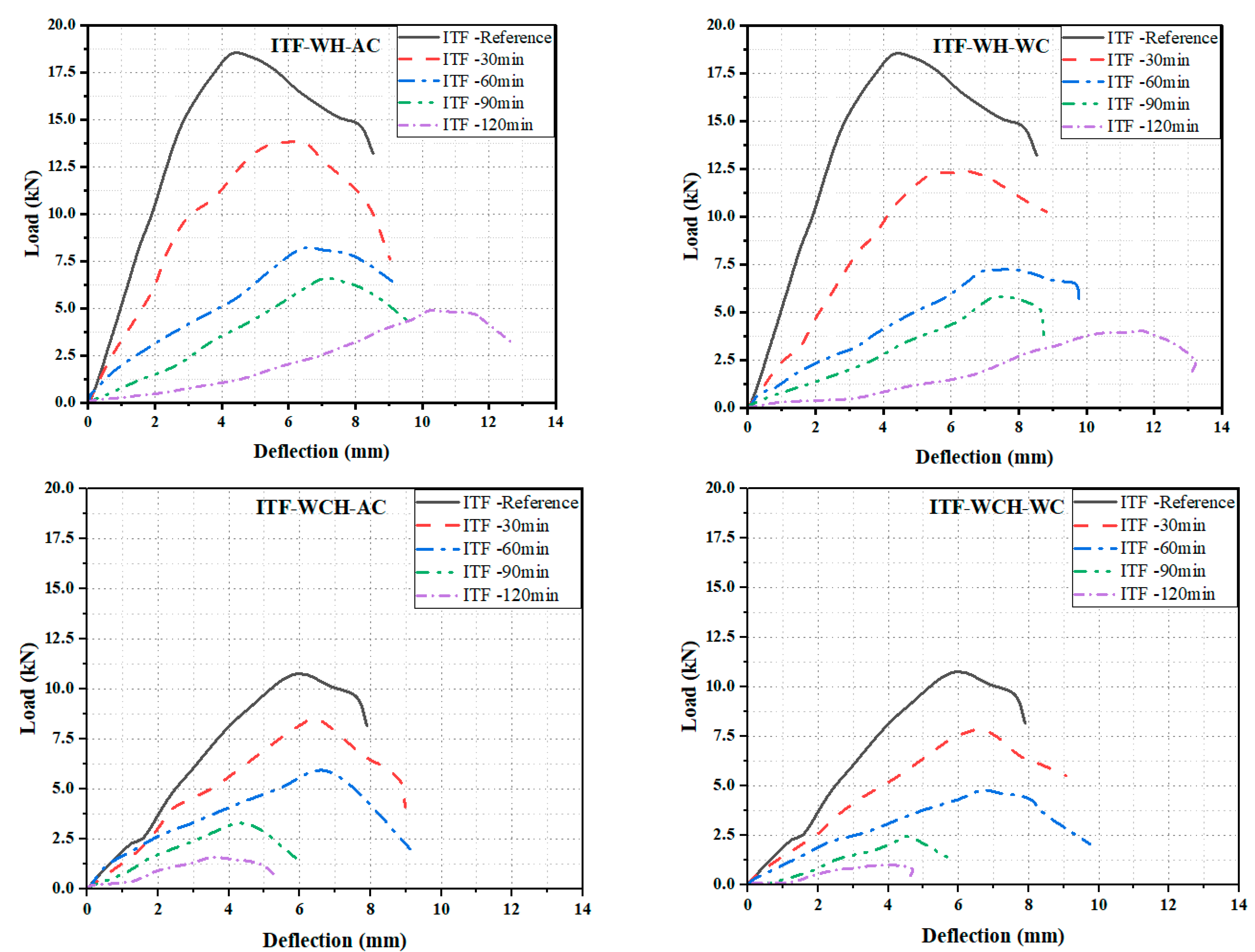
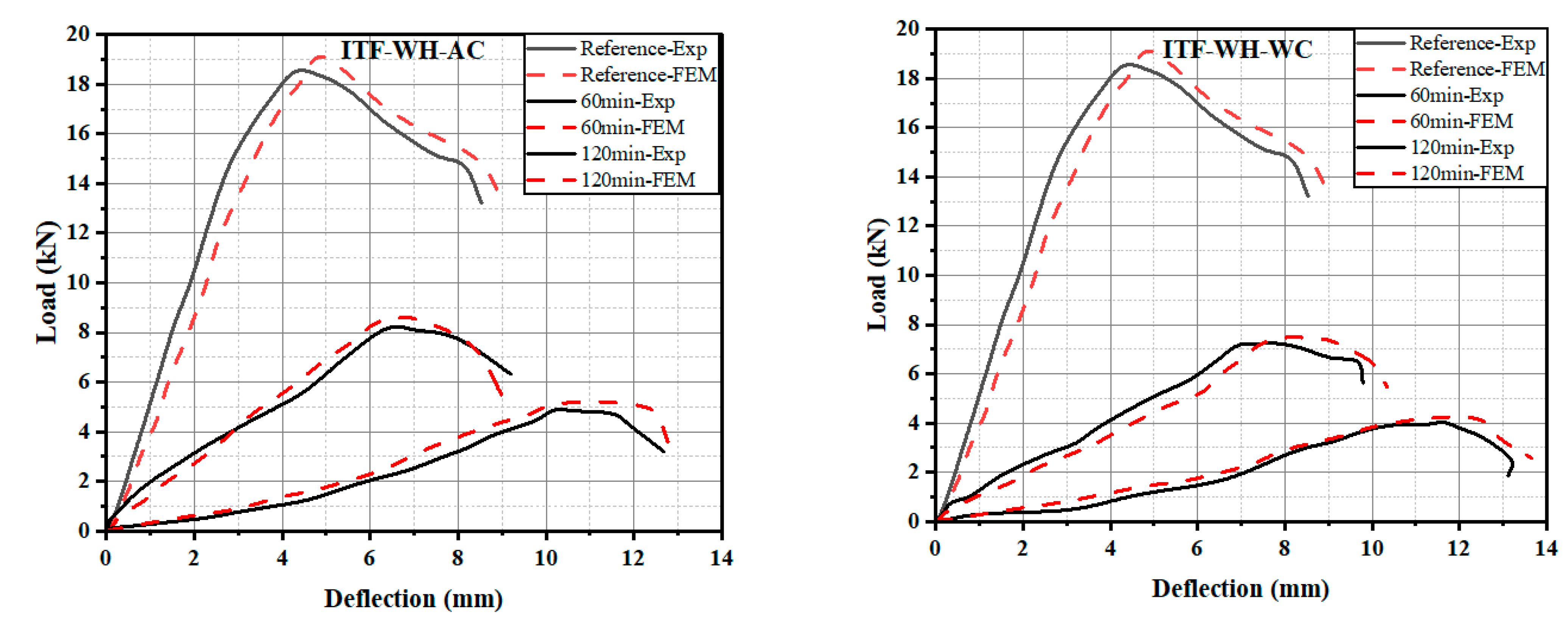
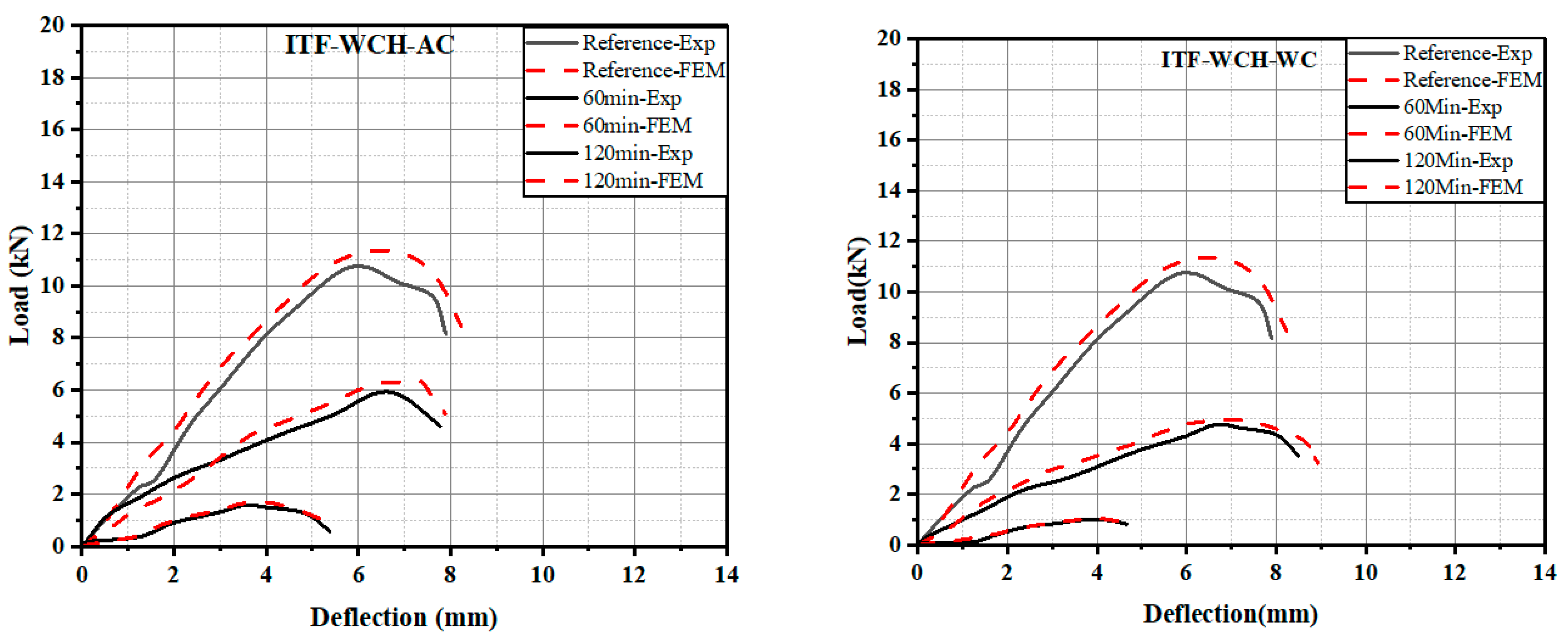
3.1.2. Load-Deflection Behaviour at ITF Condition
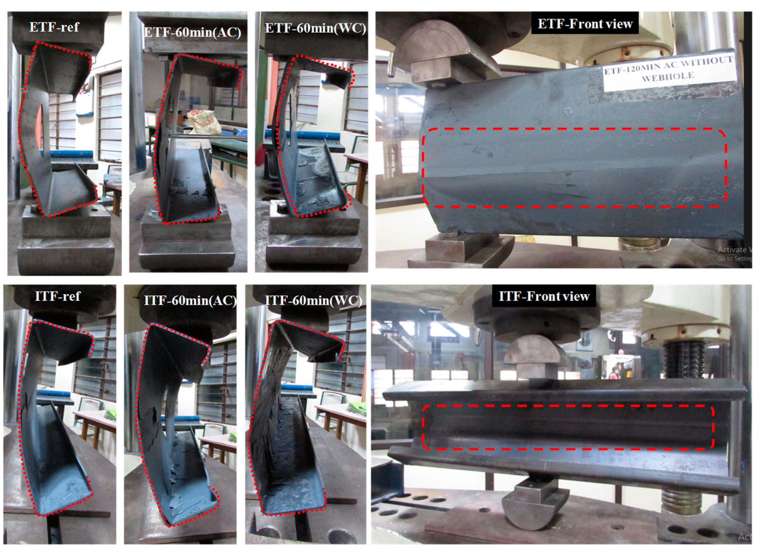
3.2. Failure Modes of High Performance CFS Specimens
4. Finite Element Modelling
4.1. Numerical Simulation
4.2. Modelling and Material Property
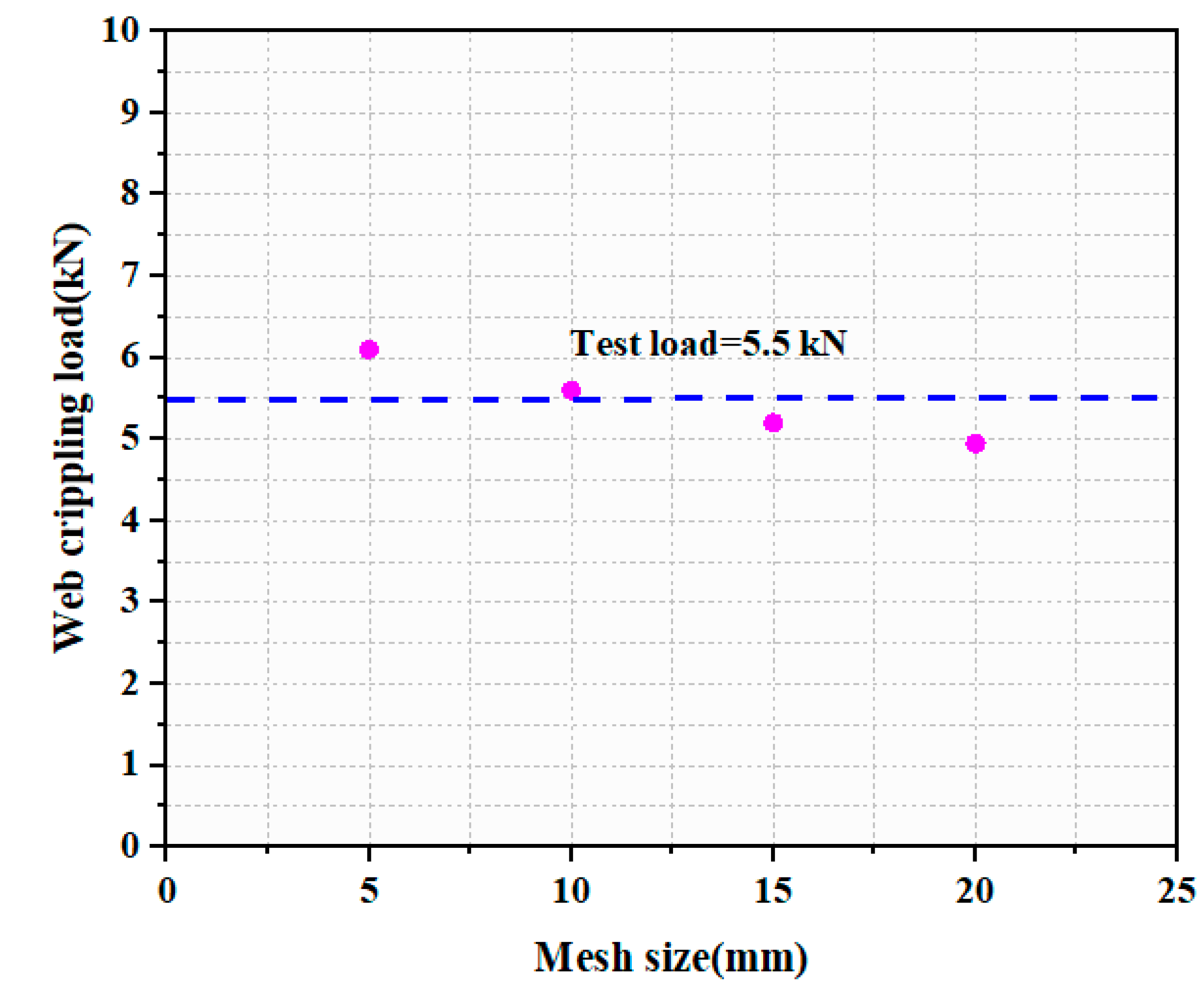
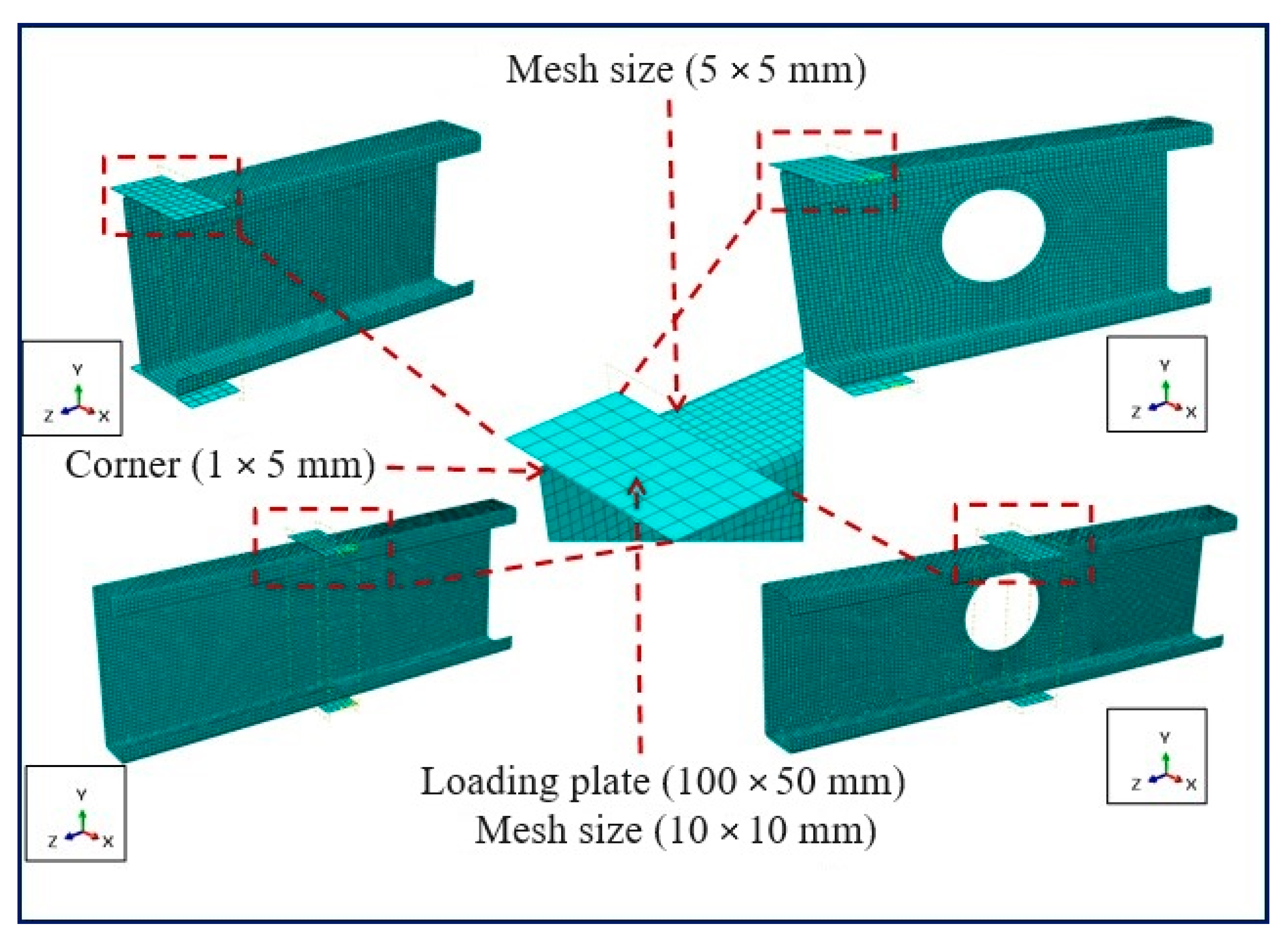
4.3. Element Type and Meshing
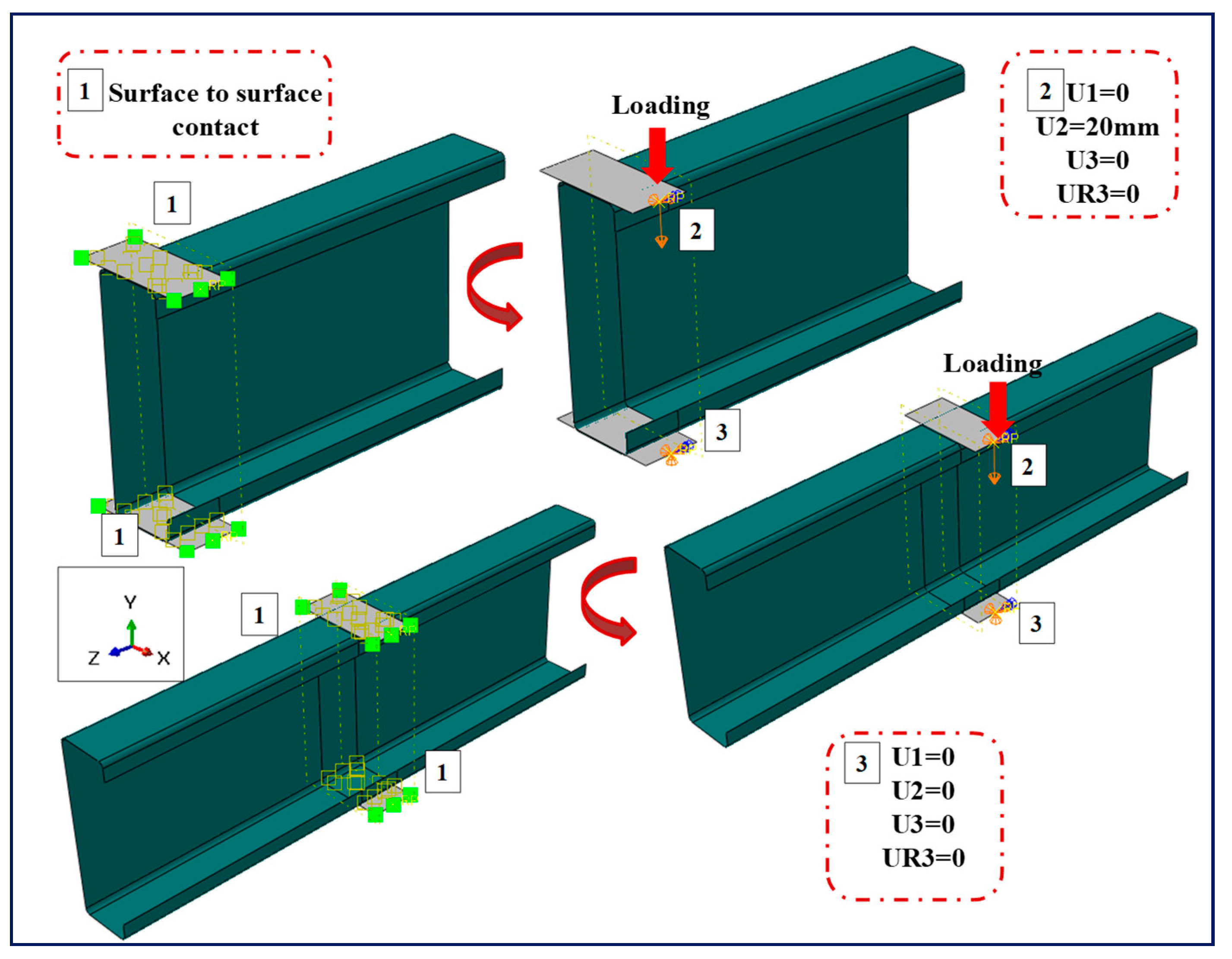
4.4. Contact Properties, Loading and Boundary Conditions
4.5. Geometrical Imperfections
4.6. Validation
4.6.1. Comparison of Load-Deflection Behaviour (Experimental Results vs. FEM)
4.6.2. Failure Modes (Experimental Results vs. FEM)
5. Conclusions
- In the case of the ETF-loading condition, without considering the effect of web hole, the water-cooled specimens showed a decrease in web-crippling capacity of about 7.5–10% when compared to air-cooled specimens. When web hole is considered, under ETF loading condition, the decrease in strength was observed between 7.5 and 15%.
- At prolonged duration of heating, i.e., at 60 min and 120 min, the decrease in residual strength was observed as 37.2% to 71.44% for WH and 36.27% to 85.38% for WCH under ETF conditions.
- An increase in lateral deflection was observed at higher duration of heating for water-cooled specimens when compared to air-cooled specimens.
- In the case of ITF-loading conditions, about 10–15% increase in strength was inferred when compared to ETF-loading conditions.
- The failure modes and web-crippling capacity of FEM for both ETF and ITF were validated with experimental results and the capacity was found to be conservative.
6. Scope for the Future Study
- Shear and web-crippling capacity of high-performance CFS specimens to be evaluated with edge stiffened and unstiffened conditions under the exposure of elevated temperature.
- To conduct a detailed parametric study on influencing parameters and proposal of new design guidelines for high-performance CFS structures under fire conditions.
Author Contributions
Funding
Informed Consent Statement
Data Availability Statement
Conflicts of Interest
Abbreviations
| CFS | Cold-Formed Steel |
| ETF | End Two Flange |
| ITF | Interior Two Flange |
| WH | Without Circular Hole |
| WCH | With Circular Hole |
| FEM | Finite Element Modelling |
References
- Jaya Kumar, G.; Kiran, T.; Anand, N.; Al-Jabri, K. Influence of fire-resistant coating on the physical characteristics and residual mechanical properties of E350 steel section exposed to elevated temperature. J. Struct. Fire Eng. 2023, 14, 228–253. [Google Scholar] [CrossRef]
- Jaya Kumar, G.; Kiran, T.; Anand, N.; Anbarasu, M.; Lubloy, E. Post-fire flexural behaviour and performance of unrestrained cold-formed steel built-up section beams: Experimental and numerical investigation. Case Stud. Constr. Mater. 2023, 18, e01978. [Google Scholar] [CrossRef]
- McIntosh, A.; Kanthasamy, E.; Poologanathan, K.; Gunalan, S.; Gatheeshgar, P.; Corradi, M.; Higgins, C. Web crippling design of channel beams: Carbon steel, stainless steel and aluminium. J. Constr. Steel Res. 2022, 196, 107427. [Google Scholar] [CrossRef]
- Sundararajah, L.; Mahendran, M.; Keerthan, P. Experimental studies of lipped channel beams subject to web crippling under two-flange load cases. J. Struct. Eng. 2016, 142, 04016058. [Google Scholar] [CrossRef]
- Chen, B.; Roy, K.; Fang, Z.; Uzzaman, A.; Chi, Y.; Lim, J.B. Web crippling capacity of fastened cold-formed steel channels with edge-stiffened web holes, un-stiffened web holes and plain webs under two-flange loading. Thin-Walled Struct. 2021, 163, 107666. [Google Scholar] [CrossRef]
- Degtyareva, N.; Poologanathan, K.; Mahendran, M. Web crippling tests of cold-formed steel channels with staggered web perforations. Thin-Walled Struct. 2021, 159, 107314. [Google Scholar] [CrossRef]
- Sundararajah, L.; Mahendran, M.; Keerthan, P. Web crippling experiments of high strength lipped channel beams under one-flange loading. J. Constr. Steel Res. 2017, 138, 851–866. [Google Scholar] [CrossRef]
- Kanthasamy, E.; Chandramohan, D.L.; Shanmuganathan, G.; Poologanathan, K.; Gatheeshgar, P.; Corradi, M.; Mcintosh, A. Web crippling behaviour of cold-formed high-strength steel unlipped channel beams under End-One-Flange load case. Case Stud. Constr. Mater. 2022, 16, e01022. [Google Scholar] [CrossRef]
- Fang, Z.; Roy, K.; Uzzaman, A.; Lim, J.B. Numerical simulation and proposed design rules of cold-formed stainless-steel channels with web holes under interior-one-flange loading. Eng. Struct. 2022, 252, 113566. [Google Scholar] [CrossRef]
- Hancock, G.J.; Pham, C.H. Buckling Analysis of thin-walled sections under localised loading using the semi-analytical finite strip method. Thin-Walled Struct. 2015, 86, 35–46. [Google Scholar] [CrossRef]
- Nguyen, V.V.; Hancock, G.J.; Pham, C.H. Analyses of thin-walled sections under localised loading for General End Boundary Conditions—Part 1: Pre-Buckling. Thin-Walled Struct. 2017, 119, 956–972. [Google Scholar] [CrossRef]
- Nguyen, V.V.; Hancock, G.J.; Pham, C.H. Analyses of thin-walled sections under localised loading for General End Boundary Conditions—Part 2: Buckling. Thin-Walled Struct. 2017, 119, 973–987. [Google Scholar] [CrossRef]
- AISI S100; North American Specification for the Design of Cold-Formed Steel Structural Members. American Iron and Steel Institute: Washington, DC, USA, 2016.
- AS/NZS 4600; Australian/New Zealand Standard Cold-Formed Steel Structures. Standards Australia: Sydney, Australia, 2018.
- EN 1993-1-3; Eurocode 3: Design of Steel Structures—Part 1–3: General Rules—Supplementary Rules for Cold-formed Members and Sheeting. National Standards Authority of Ireland: Dublin, Ireland, 2006.
- Nguyen, V.V.; Hancock, G.J.; Pham, C.H. New Developments in the Direct Strength Method (DSM) for the design of Cold-Formed Steel Sections under localised loading. Steel Constr. 2017, 10, 227–233. [Google Scholar] [CrossRef]
- Nguyen, V.V.; Hancock, G.J.; Pham, C.H. Consistent and Simplified DSM for Design of Cold-Formed Steel Structural Members under Localized Loading. J. Struct. Eng. 2020, 146, 04020090. [Google Scholar] [CrossRef]
- Johnston, R.P.; Sonebi, M.; Lim, J.B.; Armstrong, C.G.; Wrzesien, A.M.; Abdelal, G.; Hu, Y. The collapse behaviour of cold-formed steel portal frames at elevated temperatures. J. Struct. Fire Eng. 2015, 6, 77–102. [Google Scholar] [CrossRef]
- Roy, K.; Lim, J.B.; Lau, H.H.; Yong, P.M.; Clifton, G.C.; Johnston, R.P.; Wrzesien, A.; Mei, C.C. Collapse behaviour of a fire engineering designed single-storey cold-formed steel building in severe fires. Thin-Walled Struct. 2019, 142, 340–357. [Google Scholar] [CrossRef]
- Nadjai, A.; Naveed, A.; Charlier, M.; Vassart, O.; Welsh, S.; Glorieux, A.; Sjostrom, J. Large scale fire test: The development of a travelling fire in open ventilation conditions and its influence on the surrounding steel structure. Fire Saf. J. 2022, 130, 103575. [Google Scholar] [CrossRef]
- Javed, M.F.; Hafizah, N.; Memon, S.A.; Jameel, M.; Aslam, M. Recent research on cold-formed steel beams and columns subjected to elevated temperature: A review. Constr. Build Mat. 2017, 144, 686–701. [Google Scholar] [CrossRef]
- Cai, Y.; Wang, L.; Zhou, F. Lean duplex stainless steel tubular sections undergoing web crippling at elevated temperatures. J. Constr. Steel Res. 2021, 182, 106681. [Google Scholar] [CrossRef]
- Laim, L.; Rodrigues, J.P.C.; Da Silva, L.S. Experimental and numerical analysis on the structural behaviour of cold-formed steel beams. Thin-Walled Struct. 2013, 72, 1–13. [Google Scholar] [CrossRef]
- Kiran, T.; Anand, N.; Mathews, M.E.; Andrushia, A.D.; Walls, R.; Kanagaraj, B. Post-fire behaviour and improving the performance of hot rolled open sections subjected to standard fire exposure. Case. Stud. Constr. Mater. 2022, 16, e01021. [Google Scholar] [CrossRef]
- Fang, Z.; Roy, K.; Lakshmanan, D.; Pranomrum, P.; Li, F.; Lau, H.H.; Lim, J.B. Structural behaviour of back-to-back cold-formed steel channel sections with web openings under axial compression at elevated temperatures. J. Build. Eng. 2022, 54, 104512. [Google Scholar] [CrossRef]
- Li, H.T.; Young, B. Cold-formed high strength steel SHS and RHS beams at elevated temperatures. J. Constr. Steel Res. 2019, 158, 475–485. [Google Scholar] [CrossRef]
- Lu, J.; Liu, H.; Chen, Z.; Luke, B. Experimental investigation of the residual mechanical properties of cast steels after exposure to elevated temperature. Constr. Build Mat. 2017, 143, 259–271. [Google Scholar] [CrossRef]
- Chong Ren; Liusi Dai; Yuner Huang; Wenfu He, Experimental investigation of post-fire mechanical properties of Q235 cold-formed steel. Thin-Walled Struct. 2020, 150, 106651. [CrossRef]
- AISI S909-13; Standard Test Method for Determining the Web Crippling Strength of Cold-Formed Steel Beams. American Iron and Steel Institute Specification (AISI): Washington, DC, USA, 2013.
- ISO 834-1; Fire-Resistance Tests—Elements of Building Construction—Part 1: General Requirements. ISO Stand.: Geneva, Switzerland, 1999.
- ASTM E8/E8M-16; Standard Test Methods for Tension Testing of Metallic Materials. ASTM International: West Conshohocken, PA, USA, 2016.
- ABAQUS/Standard Version 6. 13, ABAQUS/CAE User’s Manual; Dassault Systèmes Simulia Corp.: Providence, RI, USA, 2013. [Google Scholar]


| Duration of Heating (min) | Yield Strength-AC (MPa) | Yield Strength-WC (MPa) | Ultimate Strength-AC (MPa) | Ultimate Strength-WC (MPa) | Elastic Modulus-AC (GPa) | Elastic Modulus-WC (GPa) | % Elongation-AC | % Elongation-WC |
|---|---|---|---|---|---|---|---|---|
| Reference | 415 | NA | 544 | NA | 211 | NA | 0.43 | NA |
| 30 | 335 | 318 | 425 | 401 | 157 | 150 | 0.38 | 0.36 |
| 60 | 255 | 237 | 385 | 360 | 146 | 142 | 0.35 | 0.33 |
| 90 | 183 | 165 | 250 | 202 | 102 | 92 | 0.3 | 0.24 |
| 120 | 147 | 140 | 210 | 190 | 65 | 54 | 0.21 | 0.20 |
| S. No | Duration of Heating and Cooling Type | Temperature as per ISO 834 | Web-Crippling Capacity (kN) | |||||||
|---|---|---|---|---|---|---|---|---|---|---|
| ETF WH | ETF WCH | ITF WH | ITF WCH | |||||||
| Exp | FEM | Exp | FEM | Exp | FEM | Exp | FEM | |||
| 1 | Reference | 0 °C | 5.619 | 5.737 | 4.914 | 5.292 | 18.565 | 19.103 | 10.795 | 11.376 |
| 2 | 60 min AC | 925 °C | 3.529 | 3.692 | 3.131 | 3.385 | 8.281 | 8.640 | 5.963 | 6.361 |
| 3 | 60 min WC | 925 °C | 3.263 | 3.573 | 2.782 | 2.986 | 7.238 | 7.503 | 4.752 | 4.962 |
| 4 | 120 min AC | 1029 °C | 1.605 | 1.780 | 0.718 | 0.768 | 4.933 | 5.232 | 1.621 | 1.023 |
| 5 | 120 min WC | 1029 °C | 1.490 | 1.585 | 0.624 | 0.644 | 4.047 | 4.195 | 1.743 | 1.083 |
| Duration of Heating | Air Cooled-ETF-without Hole | |
|---|---|---|
| Exp | FEM | |
| Reference |  |  |
| 60 min |  |  |
| 120 min |  |  |
| Duration of Heating | Water Cooled- ETF- without Hole | |
| Exp | FEM | |
| Reference |  |  |
| 60 min |  |  |
| 120 min |  |  |
| Duration of Heating | Air-Cooled-ETF with Circular Hole | |
| Exp | FEM | |
| Reference |  |  |
| 60 min |  |  |
| 120 min |  |  |
| Duration of Heating | Water-Cooled-ETF with Circular Hole | |
| Exp | FEM | |
| Reference |  |  |
| 60 min |  |  |
| 120 min |  |  |
| Duration of Heating | Air-Cooled-ITF without Hole | |
|---|---|---|
| Exp | FEM | |
| Reference |  |  |
| 60 min |  |  |
| 120 min |  |  |
| Duration of Heating | Water-Cooled-ITF without Hole | |
| Exp | FEM | |
| Reference |  |  |
| 60 min |  |  |
| 120 min |  |  |
| Duration of Heating | Air-Cooled-ITF with Circular Hole | |
| Exp | FEM | |
| Reference |  |  |
| 60 min |  |  |
| 120 min |  |  |
| Duration of Heating | Water-Cooled-ITF with Circular Hole | |
| Exp | FEM | |
| Reference |  |  |
| 60 min |  |  |
| 120 min |  |  |
Disclaimer/Publisher’s Note: The statements, opinions and data contained in all publications are solely those of the individual author(s) and contributor(s) and not of MDPI and/or the editor(s). MDPI and/or the editor(s) disclaim responsibility for any injury to people or property resulting from any ideas, methods, instructions or products referred to in the content. |
© 2023 by the authors. Licensee MDPI, Basel, Switzerland. This article is an open access article distributed under the terms and conditions of the Creative Commons Attribution (CC BY) license (https://creativecommons.org/licenses/by/4.0/).
Share and Cite
Jayakumar, G.; Kiran, T.; Nammalvar, A.; Prasad Sah, T.; Mathews, M.E.; Anbarasu, M.; Dar, A.R. Web-Crippling Capacity of High Performance Cold-Formed Lipped Steel Sections Subjected to Elevated Temperature. Buildings 2023, 13, 2436. https://doi.org/10.3390/buildings13102436
Jayakumar G, Kiran T, Nammalvar A, Prasad Sah T, Mathews ME, Anbarasu M, Dar AR. Web-Crippling Capacity of High Performance Cold-Formed Lipped Steel Sections Subjected to Elevated Temperature. Buildings. 2023; 13(10):2436. https://doi.org/10.3390/buildings13102436
Chicago/Turabian StyleJayakumar, Gunasekaran, Tattukolla Kiran, Anand Nammalvar, Tilak Prasad Sah, Mervin Ealiyas Mathews, M. Anbarasu, and A. R. Dar. 2023. "Web-Crippling Capacity of High Performance Cold-Formed Lipped Steel Sections Subjected to Elevated Temperature" Buildings 13, no. 10: 2436. https://doi.org/10.3390/buildings13102436