1. Introduction
With the development of urban transportation facilities in sea conditions, such as undersea tunnels and cross-sea bridges, there are more and more projects crossing rivers and lakes. At present, the commonly used construction methods for crossing rivers and lakes are the shield method, cofferdam method, and immersed pipe method [
1,
2,
3,
4,
5,
6]. Compared with the other construction methods, the cofferdam method is characterized by low cost, high efficiency, and low construction difficulty and it is suitable for areas with relatively slow water flow and shallow water depth [
7,
8]. However, there are fewer engineering cases related to the excavation of oversized, deep foundation pits inside cofferdams, and the form of the cofferdam structure and the spacing between cofferdams and foundation pits are related to the success or failure of engineering construction. Therefore, it is necessary to research the deformation characteristics and design optimization of cofferdam and pit enclosure structures to ensure construction safety, improve construction efficiency, and provide references for similar projects.
Extensive research has been conducted on the structural forms of cofferdams and construction plans [
9,
10,
11,
12,
13,
14] to study the support strength of squares, timber pile islands, and tipping cofferdams. Sulovska et al. [
15] used Plaxis finite element software to analyze the stability of a cofferdam backfilled with stone around the outer sheet pile wall, and the horizontal displacement of the sheet pile wall was reduced by 30%. Jiang et al. [
16] used the same software to analyze the deformation characteristics and stability of a cofferdam during the super-historic flood period, and the safety factor of the cofferdam was correlated with the cofferdam slope ratio. Wang et al. [
17] numerically simulated the excavation process for a steep can-reinforced riverbank slope using FLAC3D finite element software and established that setting single or multiple rows of steel pipe piles could improve the cofferdam’s stability. Cofferdam stability is primarily improved by changing the structural form, backfilling the stone on the outside, and adding steel pipe piles. However, there are few studies on the effect of pit excavation on cofferdams.
During the excavation of the foundation pit, the impact on the surrounding environment can be reduced by improving the support system and changing the excavation method. Wu et al. [
18] proposed a method for the Taihu Lake Tunnel; in this method, a cofferdam of double-row steel sheet piles (DSSPs) was designed to divide the overlying excavation into several closed zones. This construction method ensured minimal disturbance to the cofferdam. A bipartition wall (BPW) construction method was introduced by Zhang et al. [
19], which was developed to reduce the excavation-induced adverse impact on the supporting structures and surrounding environment for oversized, deep foundation pits. Li et al. [
20] divided large, deep foundation pits into small independent areas for excavation and proposed a construction method in separate phases to reduce their impact on the surrounding environment. Ye et al. [
21] investigated the effect of pit excavation in Hefei on the deformation of an adjacent subway tunnel and found that the closer the excavation was to the tunnel, the more sensitive the deformation was. Zhang et al. [
22] studied the effects of pits with different support and excavation methods on adjacent pipelines and found that slope-release excavation can significantly reduce pipeline deformation. Zhao et al. [
23] excavated foundation pits using rotary spray piles and a four-layer support system. According to the monitoring results, this foundation pit support system could limit the settlement around the road, the horizontal displacement of the ring beam, and the deep soil displacement of the foundation pit. These methods reduce the impact on the surrounding environment by dividing the large foundation pit into several areas, changing the support system, and using other conventional methods. However, it is not possible to directly determine the optimal distance or the effect of the excavation method on the surrounding structures.
The foundation excavation process affects the deformation of the surrounding structures, which is usually determined through on-site monitoring; however, monitoring cannot predict future development. Many scholars have used numerical simulations [
24,
25,
26,
27,
28,
29,
30] to predict the deformation of surrounding structures and the environment under different construction scenarios to provide a reference for the construction of actual projects.
In this study, we investigated the effects of the lake pit excavation process on cofferdam deformation characteristics, employing an analysis of different distances from the impact of pit excavation, a stability analysis of the use of different slopes in the excavation method, and a comparative analysis of pit excavation distance combined with the excavation method. Looking at the Jinji Lake Tunnel Project, the effect of cofferdam design optimization was verified through on-site monitoring, and the mechanism of action was analyzed.
4. Analysis of Calculation Results
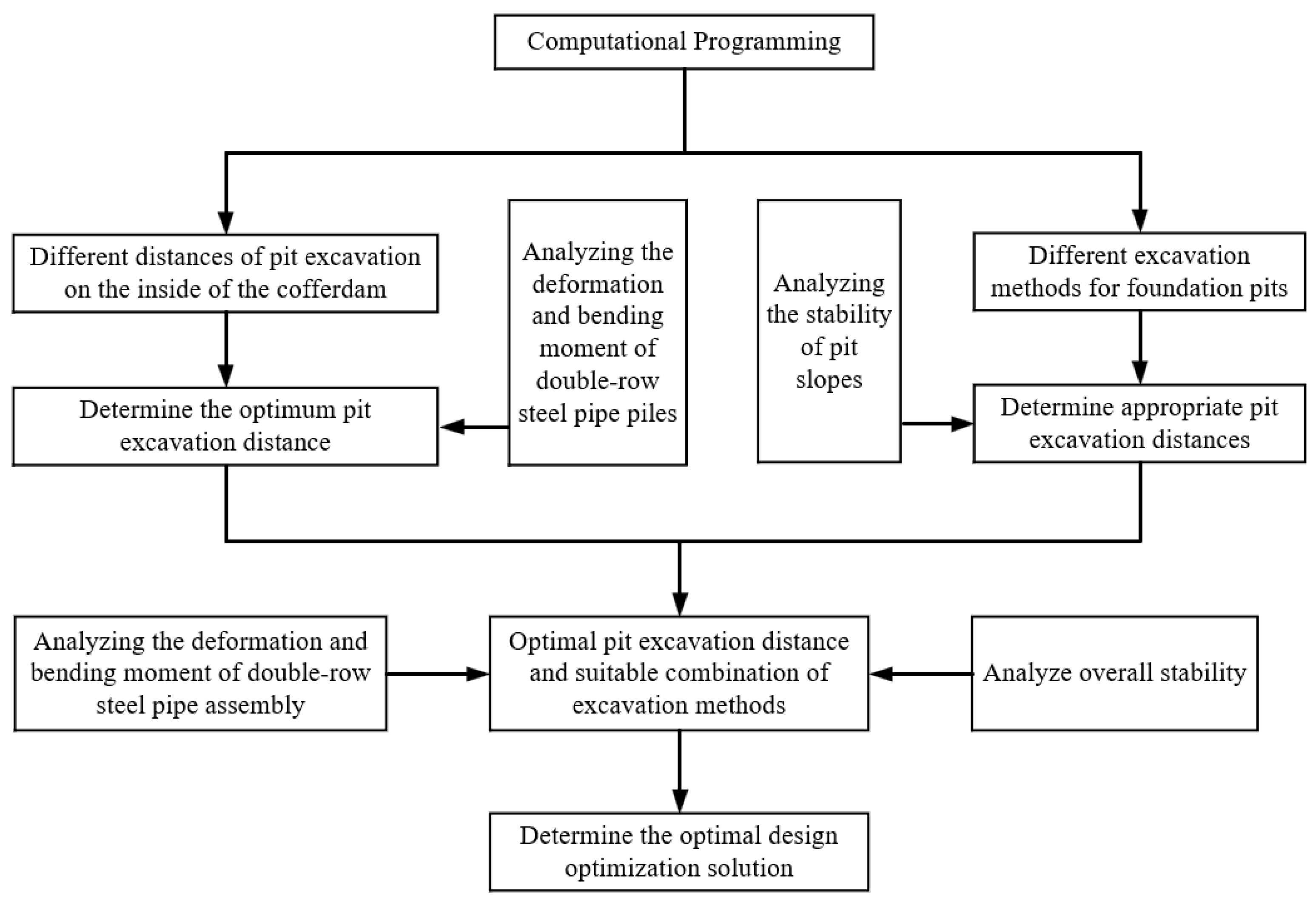
4.1. Computational Programming
Through the design and analysis of the calculation scheme, the optimal design optimization scheme was determined in terms of three aspects: different distances of pit excavation on the inside of the cofferdam, different excavation methods for the pit, and the optimal combination of pit excavation distances and excavation methods. The calculation scheme is shown in
Figure 7.
(1) The deformation and bending moments of the double-row steel pipe piles at different distances were analyzed for pit excavation with different distances on the inside of the cofferdam, comparing the piles from pit excavation one and two and the piles above and below the bottom surface of the lake to determine the pit excavation distances with the smallest impact.
(2) For different excavation methods for foundation pits, we analyzed the slope stability under different working conditions and compared different platform widths with the same aspect ratio and different aspect ratios with the same platform width to choose the appropriate excavation method for the foundation pit.
(3) Based on the research on different distances for the pit excavation and different excavation methods, a suitable combination of working conditions was selected. We analyzed the deformation, bending moment, overall stability, and the comparison of the excavation cross-section area of the double-row steel pipe piles under different combinations of working conditions and finally determined the optimal design optimization scheme.
4.2. Analysis of the Deformation of the Enclosing Piles on the Waterward Side
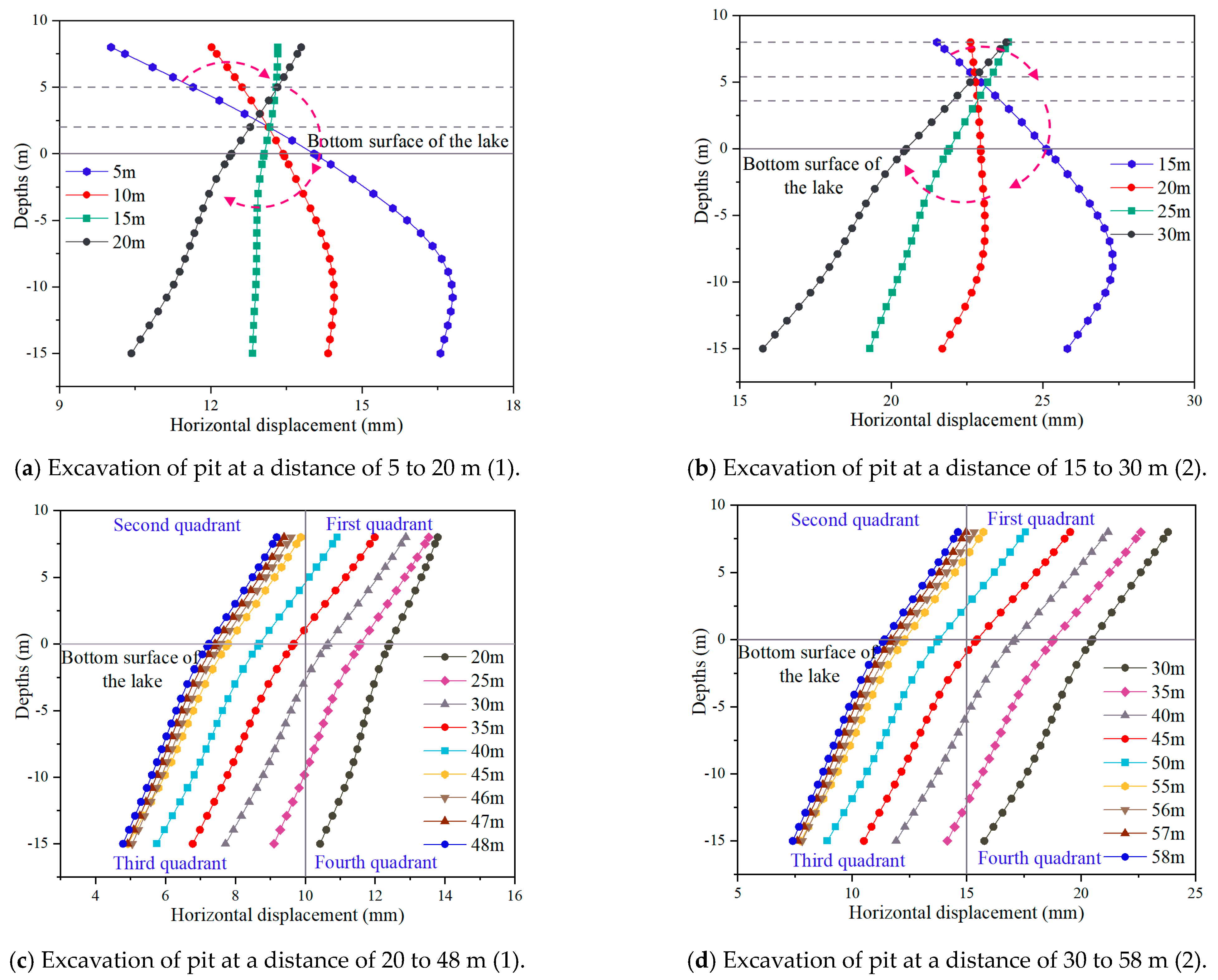
(1) As shown in
Figure 8a,b, due to the closer distance between the pit and the cofferdam, there is a greater impact from pit excavation unloading on the piles below the bottom surface of the lake, and with the increasing distance, the combined piles on the water-facing side of pit excavations one and two undergo clockwise rotational deformation, which has a greater impact on the piles above the bottom surface of the lake. The pile deforms from an “L” shape to a straight line. In pit excavation one, with the bottom surface of the lake as the dividing interface, the deformation of steel pipe piles above the bottom surface of the lake at distances of 5 m and 10 m is greater than that below the bottom surface of the lake, and due to the proximity, the unloading of the pit produces a bulge and a movement in the side slopes of the pit toward the inward direction, which drives the combined piles to the side facing the water. When the distance is 15 m, the deformation of the combined piles is approximated as a straight vertical translation due to the increase in distance and the effect of pit unloading on the piles’ movement towards the backwater side. At distances of 5, 10, and 15 m, the combined pile deformations are rotated clockwise using a position 2 m above the bottom surface of the lake as the axis point.
In pit excavation two, due to the use of a 1:2 aspect ratio slope release excavation form, the distance to the cofferdam is greater than the distance for excavation one, so when the distance is 20 m, due to the increase in excavation depth, the combination piles at a depth −8 m below are mainly subject to inward movement due to the slope of the pit. When the deformation of the pit tilts inward, the combination piles at a depth −8 m above are subject to the unloading of the pit generated by the uplift and the inward movement due to the pit slope of the common pile body seems to be a straight vertical translation. At depths greater than −8 m, the pile body is approximately vertically translated in a straight line due to the joint action of loading and unloading and the inward movement of the foundation slope. The axial point of rotation from a distance of 15 m to a distance of 20 m is 5.6 m above the bottom surface of the lake, and it can be raised under the influence of the augmentation of the unloading from pit excavation one. When the distance is greater than 20 m, it is mainly affected by the inward movement.
(2) As shown in
Figure 8c,d, when the distance between the excavation location of the foundation pit and the cofferdam is more than 20 m, the overall deformation of the pile decreases with the increasing distance, and the greater the pile length is, the smaller the deformation. The transformation of the combined piles into a diagonal distribution is mainly due to the inward movement of the slopes of the pit excavation. A plane-rectangular coordinate system was established with the bottom surface of the lake and horizontal displacements of 10 mm and 15 mm as dividing lines. In pit excavation one, the distances of 20 m and 45 m cross two quadrants, and when the distance is greater than 45 m, the deformation of the whole of the combined piles is less than 10 mm. In the range from 20 to 45 m, the combined piles all pass through three quadrants, whereas in the range near 35 m, the combined piles pass through the first and third quadrants. When the distance is greater than 35 m, the combined piles have a displacement of less than 10 mm for the part of the piles above the bottom surface of the lake, and when the distance is less than 35 m, the combined piles have a displacement greater than 10 mm for all of the piles above the bottom surface of the lake. In pit excavation two, the excavation distance is greater and the excavation area smaller compared to excavation one, so the deformation increases to a lesser extent than in excavation one. When the distance is greater than 47 m, the deformation of the whole combined piles is less than 15 mm.
4.3. Analysis of Deformation of Backwater-Side Enclosure Piles
(1) As shown in
Figure 9a,b, the rotation and deformation trends for the steel pipe pile on the backwater side are the same as those for the combined piles on the waterward side, but the rotation angle of the steel pipe piles on the backwater side is smaller than that of the combined piles on the waterward side. In pit excavation one, with a distance of 20 m, the deformation of steel pipe piles above the bottom surface of the lake is less than that below the bottom surface of the lake. For foundation pit excavation two, with a distance of 30 m, the combined piles at depths −5 m above, due to the foundation pit unloading generated by the uplift and the foundation pit, slope to the inner side of the movement of the joint role of the pile body and approximate a straight line vertical translation. Depths below −5 m are mainly subject to rumbling from pit unloading and slope towards the waterward side.
In pit excavation one, the point where the shaft rotates from a distance of 5 m to a distance of 10 m is at a location 3 m above the bottom surface of the lake, the point where the shaft rotates from a distance of 10 m to a distance of 15 m is at a location 1 m above the bottom surface of the lake, and the point where the shaft rotates from a distance of 15 m to a distance of 20 m is at a location 4.5 m above the bottom surface of the lake. In pit excavation two, the point where the axis rotates from a distance of 5 m to a distance of 10 m is at a location 5 m above the bottom surface of the lake, the point where the axis rotates from a distance of 10 m to a distance of 15 m is at a location 2 m above the bottom surface of the lake, and the point where the axis rotates from a distance of 15 m to a distance of 20 m is at a location 8 m above the bottom surface of the lake. Due to the effect of the unloading augmentation of pit excavation one, pit excavation two has a higher axis for the point of rotation.
(2) As shown in
Figure 9c,d, we established the plane right-angle coordinate system. When the distance between the excavation position of the foundation pit and the cofferdam is more than 20 m, the steel pipe pile gradually tilts to the backwater side while the deformation gradually decreases with the increasing distance, and the deeper the pile length is, the smaller the deformation. The deformation of steel pipe piles above the bottom surface of the lake is approximately straight, and the deformation of steel pipe piles demonstrates approximately vertical translation with the increase in distance. Due to the structural form of the double-row steel pipe pile combination, the water pressure on the water-facing side is mainly transmitted to the combination of steel pipe piles and inter-pile soils, and the inter-pile soils themselves can provide a certain level of horizontal resistance so that the steel pipe piles on the backwater side are less affected. In pit excavation one, when the distance is more than 45 m, the overall deformation of the steel pipe piles is less than 10 mm, and in pit excavation two, when the distance is more than 47 m, the overall deformation of the steel pipe piles is less than 15 mm.
4.4. Bending Moment Analysis of Double-Row Steel Pipe Piles
As shown in
Figure 10, with the gradual increase in the distance, the bending moment of the double-row pile gradually decreases, but the deformation law for the double-row pile bending moment does not change. The bending moment curve for the front row of piles has a reverse “S” shape and the bending moment curve for the back row of piles has an “S” shape. Due to the similarity of the double-row steel pipe piles and the end of the cantilever, there is a maximum value for the bending moment near the bottom surface of the lake, and the bending moment of the combined piles on the water-facing side is larger than the bending moment of the steel piles on the backwater side. With the increase in distance, the deformation patterns of the bending moments of the front and rear rows of steel pipe piles above the lake bottom surface do not change, indicating that the front and rear rows of steel pipe piles above the lake bottom surface are mainly affected by the water pressure, and the excavation of the foundation pit mainly affects the steel pipe piles below the lake bottom surface. As the distance increases further, the bending moment of the front row of steel pipe piles below the bottom surface of the lake decreases gradually, while the bending moment of the back row of steel pipe piles is less related to the distance. The maximum value of the positive bending moment of the combined piles on the waterward side appears near the bottom surface of the lake, and the maximum value of the negative bending moment appears nearly 10 m below the bottom surface of the lake. The maximum value of the positive bending moment of the steel pipe piles on the backwater side appears nearly 1 m below the bottom surface of the lake, and the maximum value of the negative bending moment appears nearly 2.5 m above the bottom surface of the lake.
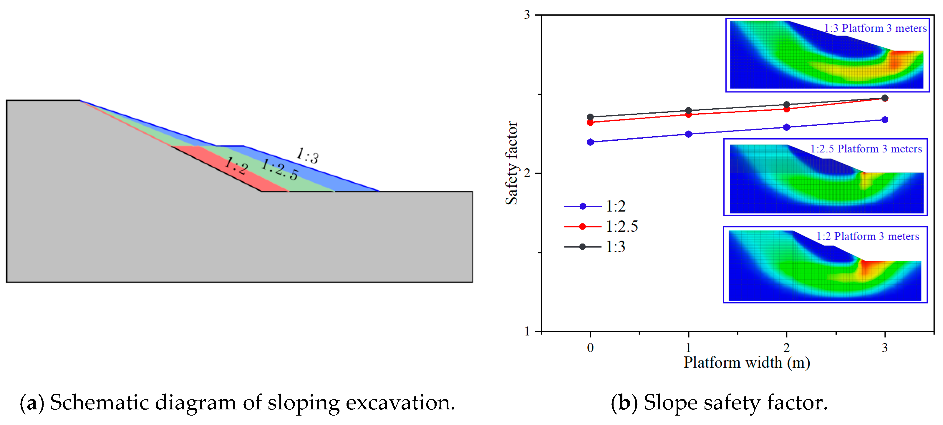
4.5. Stability Analysis of Pit Slopes
To compare the feasibility and safety of excavation with different slopes, a finite element model was established according to the soil parameters of the site, as shown in
Figure 11a, and the strength discount method was used for calculation. The safety factor is not only related to the aspect ratio but also to the platform width. As shown in
Figure 11b, for the same platform width, the smaller the aspect ratio is, the greater the safety factor. For the same aspect ratio, the greater the platform width is, the greater the safety factor. From the 1:2 aspect ratio to the 1:2.5 aspect ratio, the safety coefficient increases significantly, and from the 1:2.5 aspect ratio to the 1:3 aspect ratio, the safety coefficient increases slowly. Under the condition of a platform width of 3 m, the safety coefficient of a 1:2.5 aspect ratio is 2.474, and the safety coefficient of a 1:3 aspect ratio is 2.476; the safety coefficients of the two are almost equal. By analyzing the finite element results for the platform width of 3 m and different aspect ratios, it was found that the slip fracture surfaces all show circular arcs, and the areas of larger plastic strains are all at the foot of the slope, indicating that the plastic zone of the slope is not penetrated and no slip damage occurs.
4.6. Analysis of Deformation and Stability of Cofferdam with Different Excavations of the Foundation Pit
Through the stability analysis of the sloping excavation, the excavation method with a platform width of 3 m and 1:2, 1:2.5, and 1:3 aspect ratios was selected. As shown in
Figure 12, for the excavation of foundation pit one, the deformations of the combined steel pipe piles on the water-facing side and the steel pipe piles on the backwater side with the three different aspect ratios are very close. For pit excavation two, the three different height-to-width ratios have different deformations, and the deformation size relationship is 1:2 > 1:2.5 > 1:3. Above the bottom surface of the lake, the deformation of the combined steel pipe piles on the water-facing side decreases gradually from the top of the piles to the end of the piles, and the maximum horizontal displacement occurs at the top of the piles. This displacement is maximized at the top of the steel pipe piles on the water-facing side under the action of the tie rods. Below the bottom surface of the lake, the horizontal displacement of the steel pipe piles on the backwater side is significantly larger than that of the combined steel pipe piles on the waterward side. There are three main reasons for this: the first is that the waterward side is further away from the excavation of the foundation pit compared to the backwater side; the second is that the embedment depth of the steel pipe piles on the waterward side is greater than that of the steel pipe piles on the backwater side; and the third is that there is an inter-pile between the waterward side and the backwater side, and the gravitational force of the soil between the piles can increase the vertical stress on the soil body below the inter-pile and this vertical stress can increase the horizontal resistance of the soil.
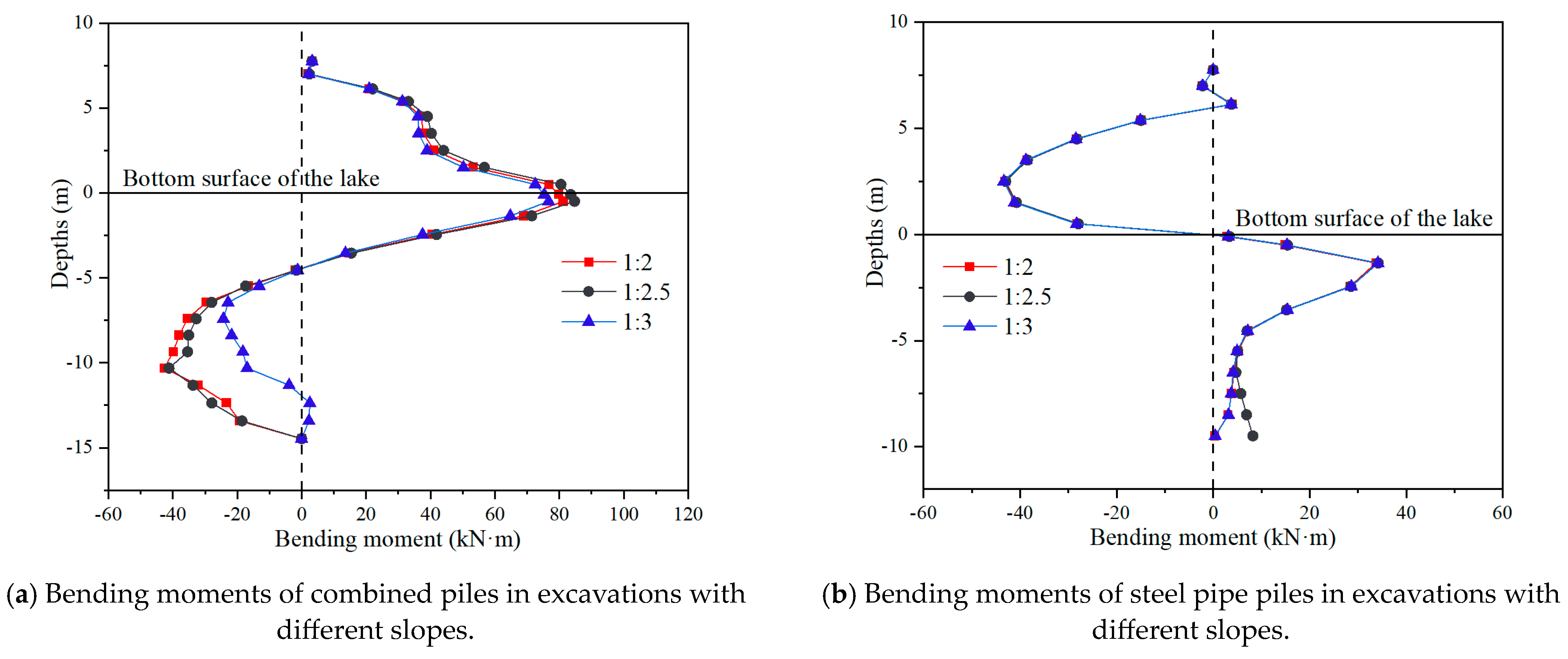
As shown in
Figure 13, the effects of the three different height-to-width ratios on the bending moments of the piles are very small, and the bending moments of the steel pipe piles on the backwater side hardly change from the top of the piles to the end of the piles. However, the combined piles on the waterward side change slightly under the combined effect of the water pressure and the excavation of the foundation pit. In the height range of the lake, the bending moment decreases as the height-to-width ratio decreases, and at the depths below 5 m in excavation two, the smaller the height-to-width ratio is, the smaller the bending moment is, which is due to the deep embedment of the combined piles on the water-facing side, which hinders their deformation.
As shown in
Figure 14, the intensity discount method was used to analyze the pit excavation with three aspect ratios. In pit excavation one, plastic areas appeared in the slopes and cofferdams with the three aspect ratios, but there was no penetration, which indicated that the cofferdams and the slopes had the same degree of danger, and the safety coefficients for the aspects ratios of 1:2, 1:2.5, and 1:3 were 3.60, 3.80, and 3.87, respectively. In pit excavation two, for the three aspect ratios, only the side slopes showed plastic areas, and all of them showed plastic deformation at the foot of the slope, but no penetration occurred, indicating that the danger for the side slopes at this time was greater than that for the cofferdams, and the coefficients of safety for the aspects ratios of 1:2, 1:2.5, and 1:3 were 1.99, 2.20, and 2.30, respectively. There was not a great difference between the coefficients of safety for the aspects ratios of 1:2.5 and 1:3. A comparison of the excavation cross-sections for both the 1:2.5 and 1:3 aspect ratios revealed that the 1:2.5 excavation cross-section was 5.38% smaller than the 1:3 excavation cross-section, as shown in
Figure 15, and that the use of the 1:2.5 aspect ratio could save costs and reduce the duration of the project.
6. Conclusions and Recommendations
In this paper, the combination of numerical simulation and on-site monitoring was used to study the structure of a cofferdam, and some understanding of regularities was obtained. It was found that, when large-scale pit excavation was carried out inside the cofferdam, the appropriate pit excavation distance and excavation method could effectively protect the cofferdam’s safety when the actual conditions of the project permitted it.
(1) The greater the distance between the pit and the cofferdam, the smaller the influence on the cofferdam will be, and the deeper the embedding of the pile, the smaller the deformation of the pile buried in the soil. If the excavation depth is 10 m and the distance between the pit and the cofferdam is greater than 47 m, the deformation of the whole pile will be less than 15 mm.
(2) With the same platform width in the slope excavation, the smaller the aspect ratio is, the greater the safety coefficient will be; with the same aspect ratio, the wider the platform is, the greater the safety coefficient will be. When the aspect ratio and platform width increase to a certain degree, the safety coefficient tends to stabilize, and the selection of the appropriate aspect ratio and platform width is effective in ensuring safety.
(3) When the pit is far away from the cofferdam, the appropriate sloping excavation method can ensure a reduced impact on the cofferdam and overall stability. Field application showed that the appropriate pit excavation distance and method effectively reduced the impact on the cofferdam, providing a reference for the design and construction of cofferdam pit excavations in lakes.
(4) In this paper, wave loads were not considered in the numerical simulation, and the effect of the cofferdam on the pit excavation under dynamic loads should be considered in subsequent work. In the stability analysis of the cofferdam, only the pit excavation was studied in detail, and we did not study the influence of the cofferdam structural form. Subsequent work can study the cofferdam pile spacing, the number of layers of tie rods, and other aspects.


