Article

Seismic Performance of Built-In Continuous-Column Steel Moment Frame with Low-Damage CPSFC at Column Bases

1
School of Urban Construction, Wuhan University of Science and Technology, Wuhan 430081, China
2
Hubei Provincial Engineering Research Center of Urban Regeneration, Wuhan University of Science and Technology, Wuhan 430081, China
3
Wuhan Urban Railway Construction Investment & Development Co., Ltd., Wuhan 430000, China
4
School of Civil and Hydraulic Engineering, Huazhong University of Science and Technology, Wuhan 430074, China
*
Author to whom correspondence should be addressed.
Buildings 2023, 13(1), 66; https://doi.org/10.3390/buildings13010066
Submission received: 21 November 2022 / Revised: 19 December 2022 / Accepted: 26 December 2022 / Published: 27 December 2022

Abstract

:
Integrating the concepts of frictional energy dissipation and low-damage mechanism, this paper proposes a built-in continuous-column (BCC) steel moment frame structure with low-damage cover plate slip-friction connections (CPSFCs) at the column bases. The slip-friction connections can convert the buckling energy dissipation of the column into frictional energy dissipation, and the continuous column can improve the lateral deformation mode of the structure under seismic action. The strength and stiffness deterioration characteristics of the material were considered in the simulation of the seismic performance of the structure, and the simplified numerical models of CPSFCs and continuous columns were established in OpenSees. Comparative analyses were carried on a seven-story steel frame, steel moment frame (SMF) with CPSFCs at the column bases (CPSFC–SMF), and a built-in continuous column steel frame (BCCF) with CPSFC at the column bases (CPSFC–BCCF). The results showed that CPSFC slightly reduced the bearing capacity of the steel moment frame but minished the structural stiffness degradation and increased the ductility of the structure. The setting of CPSFC changed the plasticity hinge sequence of the structure, resulting in a homogeneous deformation between stories. The CPSFC–BCCF had the best damage pattern and the most uniform inter-story energy dissipation.

1. Introduction

Damage control mechanisms targeting life safety are the essence of current seismic design. With the implementation of the concept of sustainability, there is a clear and urgent requirement to shift to performance-based damage control or low-damage design philosophy and technologies [1]. Under the random action of an earthquake and the P-Δ effect, if inter-story displacement is concentrated in a particular story, it will lead to weak story damage [2,3]. In actual earthquake damage, “strong columns” in the traditional “strong column–weak beam” mechanisms do not have the expected large stiffness effect [4,5,6], which may prevent the collapse of a weak story, but do not predict the actual collapse patterns of structures [7]. Integrating economic, life cycle safety, and sustainable development considerations to control damage to structure components is conducive to improving the seismic resilience and post-earthquake rehabilitation of structures [8]. Qu et al. [4] indicated that the key components of a structural system that are continuous along the height and have sufficient stiffness can result in uniform damage to stories and that the structure achieves a global type of yielding mechanism. A large number of studies have shown that the arrangement of key elements with vertical continuous stiffness in a structure is an effective measure for the damage control of a structure as a whole [9,10]. Francisco et al. [11] used an external arrangement of stiff rocking cores to strengthen steel frames in an SAC project; the results showed that stiff rocking cores along the height improved seismic performance. Feng et al. [12] applied rocking walls to buckling-restrained braced frames to alleviate the problem of inter-story displacement concentration. Li et al. [13,14] a built dissipative continuous column (DCC) into a steel frame structure and showed that DCC can effectively reduce the maximum inter-story displacement of structures. Li et al. [15] summarized and simplified different forms of key elements providing stiffness to built-in and external continuous columns (BCC) and compared them. The results showed that they are equivalent, and built-in continuous columns can solve the problems of site constraints and construction complexity. Compared to an external continuous column, BCC is integrated within the frame and is relatively easy and feasible to construct and design as a new seismic system.
Continuous columns can achieve damage control of a structure and form an ideal global-type collapse mode, which allows plasticity hinges to appear at column bases. As plasticity hinges increase, the main body of a structure shows severe buckling damage, increasing the difficulty of post-disaster reconstruction [16,17]. On the other hand, first-story frame columns are usually subjected to large axial and shear forces, which may lead to axial shortening and loss of bearing capacity when they form plasticity hinges, causing a serious impact on the overall collapse performance of the structure [18].
The use of slip-friction connections in structures is one effective way to reduce plastic damage in structural elements. Popov et al. [19] applied slip-friction connections to steel beam-column joints and developed a rotational slotted bolted connection (RSBC), which was applied to frame beam ends to reduce damage of the frame beams. Since then, researchers have proposed slip-friction connections for beams and columns and have carried out extensive research; the results verified the feasibility of using slip-friction connections to reduce structural damage [20,21]. Borzouie et al. [22] studied the cyclic loading performance of sliding hinge joints applied to steel frames at column bases. Benedetto et al. [23] studied the effect of low-damage friction joints on the global structures of steel frames; at the end of the test loading, almost no damage was observed. Zhang et al. [24] conducted a quasi-dynamic test on a self-centering steel frame substructure with intermediate columns containing friction dampers. The results showed that lateral stiffness resistance and energy dissipation capacity were greatly improved. A large study was carried out on the new seismic techniques for low-damage connections. Additionally, the effect of column base connections on the seismic and collapse performance of multi-story steel moment frames was investigated by Freddi et al. [25,26]. Under these research backgrounds, the present work adopted the cover plate slip-friction connection (CPSFC) to the column base of a steel frame, which used friction to dissipate energy during an earthquake so that the damage mode of the underlying frame column changed to the concentrated damage of specified energy-consuming elements and the advantages of a flexible and convenient arrangement and easy installation and disassembly are conducive to the replacement of damaged members after a disaster.
This work integrated novel seismic technologies, such as the continuous column concept, the column base energy dissipation mechanism, and slip-friction energy dissipation connections, to construct an innovative built-in continuous column steel frame (BCCF) structural system with cover plate slip-friction connections (CPSFC) at the column base from the system level, which is simply named CPSFC–BCCF, as shown in Figure 1. The built-in continuous column (BCC) is able to provide vertical continuous stiffness to the structure, effectively resolving the concentration of displacements between stories of the structure and facilitating the formation of an overall energy dissipation mode. The CPSFC is used to avoid damage to the main frame through frictional energy dissipation instead of buckling energy dissipation at the column bases.
To investigate the seismic performance of CPSFC–BCCF structure, the design and experimental analysis of the low-damage performance of CPSFC was firstly carried out and the numerical simplified model of CPSFC was validated. Then, three seven-story comparison frames were built in OpenSees. IDA and pushover analysis were used to investigate the seismic performance and deformation modes of different structural systems: a normal steel moment frame (SMF), a steel moment frame with CPSFC at the column base (CPSFC–SMF), and a steel moment frame with CPSFC and BCC (CPSFC–BCCF).

2. Design of CPSFC

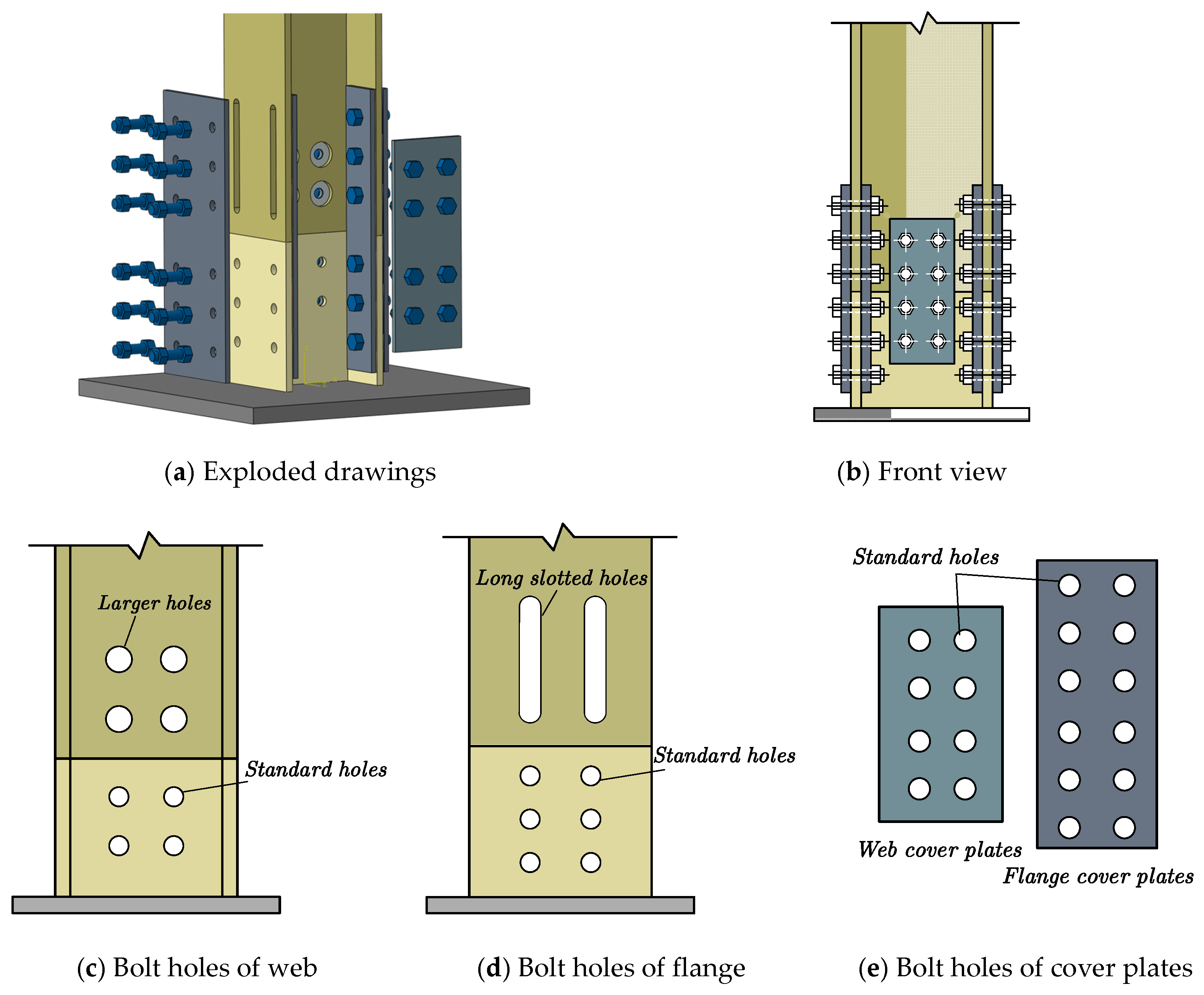
2.1. Basic Principle

The details of the CPSFCs are shown in Figure 2. The upper and lower columns are connected by cover plates at the flanges and webs. The upper column has long, slotted holes at the flange and large, circular holes at the web. The lower column flange and web are standard holes. The web and flange cover are standard holes, as shown in Figure 2c–e. The contact surfaces of the flange cover plates, the frictional dissipation energy between the cover and the frame column, is stabilized by sandblasting the web cover plates and frame columns. When the slip moment is reached, the upper column rotates around the flange on one side of the lower column. The form of the rotation of the CPSFC is shown in Figure 3. The long, slotted hole in the upper column flange and the large, round hole in the web ensure that the upper column is mainly subjected to frictional forces when sliding and rotating and that screws are not crushed against the wall of the hole. The cover plate uses standard holes. The bolts are installed tightly, and a high-strength bolts’ connection plays the role of applying preload and positioning. When the upper column is rotated, it does not drive the bolts to slide and the CPSFC rotates smoothly. The frictional energy between the steel column and the cover plates can replace the yielding energy of the column itself. The frame column remains elastic, thus achieving low or no damage to the main part of the structure.

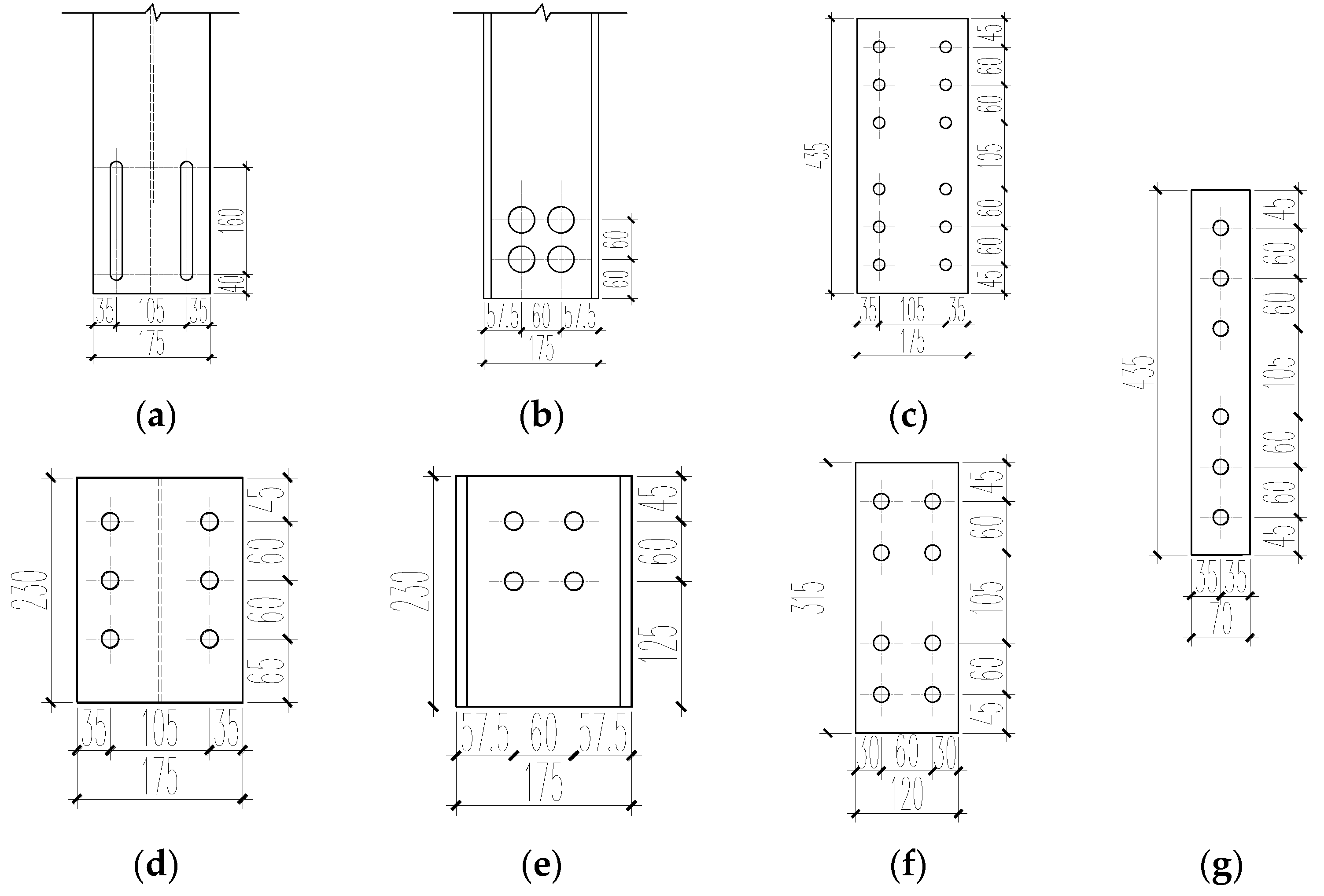
2.2. Analysis of Force Performance and Design

The stress state of the CPSFC at the column bases under the action of axial force (N), moment (M), and shear force (V) is shown in Figure 3. F c is the squeezing force between the upper and lower columns at the rotation point P. F f is the friction between the cover plates and flange of the column base. F w is the friction between the web cover plates and the web of the column base. The h is the height of the column section. The t f is the thickness for the flange of the column section. The θ p is the rotation angle of the upper column.
Based on the state of equilibrium of forces at the point of rotation P, Equations (1)–(6) can be derived for each parameter in the M - θ theoretical curve of CPSFC in Figure 4.
M D = N · ( h t f ) / 2
M 1 = M D + M f
M f = F f · ( h t f ) + 2 · F w · ( h t f ) / 2
M 2 = M 0 + M f
M 3 = M 2 2 · M f
M 4 = M 0 M f
where M D is the bending moment required to overcome the axial force, M f is the bending moment generated by the friction between the cover plates and the column, M 1 is the starting slip moment after the CPSFC has overcome axial force, M 2 is the calculated value of the bending moment when the rotation ratio of the upper column is θ p , M 3 is the starting slip moment after unloading, and M 4 is the bending moment required when the rotation ratio of the upper column is null.
To ensure that the frame columns are not excessively damaged after an earthquake, the ultimate bending moment M 2 when the CPSFC reaches ultimate rotation should be less than the plastic bending moment of frame columns. The CPSFC can be designed according to this principle.
The friction coefficient between the flange of the frame columns and cover plates is denoted as μ f and that between the web of the frame columns and cover plates is denoted as μ w . The friction between the flange and cover plates can then be calculated from Equation (7):
F f = μ f · n s · P
F w = μ w · n s · P
where n s is the number of friction surfaces for the transmission of high-strength bolts. Similarly, the friction between the web and cover plates can be calculated for the frame columns, as shown in Equation (8).

3. Finite Element Model of the CPSFC and Validation

3.1. Simplified Model

A simplified finite element model of the CPSFC was proposed by Elettor and built in OpenSees, as shown in Figure 5a [26,27]. In this model, the Parallel-1 and Parallel-2 materials were formed by a Steel02 constitutive model and ENT material in parallel for the simulation of frictional behavior between the cover plates and flange or web, as shown in Figure 5b,c, respectively. ENT is a uniaxial elastic, no-tension material subjected to compression. Steel02 is a steel material in OpenSees. The yield strength of the Steel02 constitutive model was calculated from the frictional forces on the flanges and webs of the frame columns; the modulus of elasticity of the Steel02 constitutive model was set to a larger value during the simulation to produce a smaller deformation when the Steel02 entered the yielding phase for the simulation of a state where the upper column is about to rotate. To simulate the mechanical behavior between the upper and lower column sections approaching infinity, the modulus of elasticity of an ENT material was set to 104 times the modulus of elasticity of the beam-column elements. The upper and lower rigid crossbeams simulated two sections where the upper and lower columns were in contact; so, the length was the height of the column section. Both rigid crossbeams used elastic beam and column elements, which had a modulus of elasticity that was 104 times that of the frame beam and column elements.

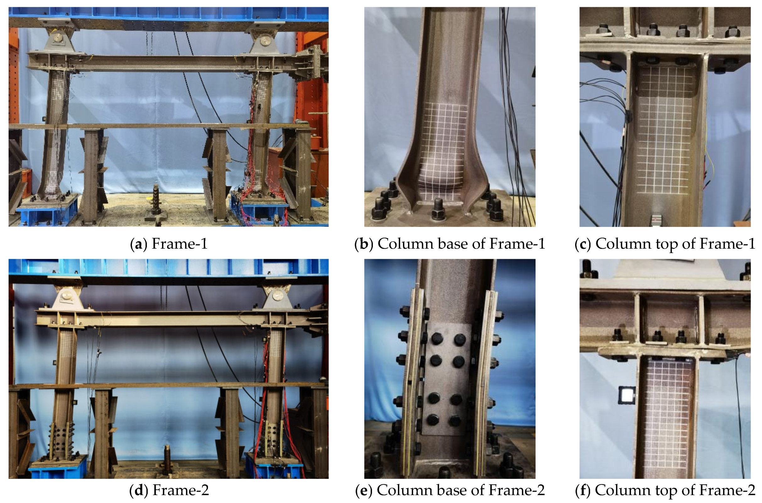
3.2. Experimental and Finite Element Model Validation of the CPSFC

3.2.1. Test Materials and Methods

Quasi-static tests were carried out on two single-story and single-span steel frames. Specimen Frame-1 was a normal steel frame, and specimen Frame-2 was a steel frame with CPSFCs at the column bases. The frame was a beam-through with a column height of 1.75 m and a beam span of 2.4 m. The section of the frame beam and column was HT 175 × 172 × 6.5 × 9.5, and the steel was Q235B. A detailed design of the CPSFC is shown in Figure 6.
The cover plates were Q355B and were connected by friction high-strength bolts of grade 10.9 with an applied bolt preload of 50–60% of the standard bolt preload [23]. The top plates of the column were connected to the beam by M20 friction high-strength bolts of 10.9, and the applied bolt preload was 155 kN. The filling brass shims between the friction pairs of the steel plates helped to reduce vibration and ease bolt loosening [28]. Given that the plasticity hinge at the column bases was generally located at 1.25–1.85 times the height of the column section [29], the height of the lower steel column was set at 230 mm to meet construction requirements and accommodate the number of bolts. The axial compression ratio applied to the frame columns was 0.2. The material properties of the flanges and webs of the steel and the cover plates were tested according to the standard GB/T 228.1-2021 [30]; the results are shown in Table 1.

3.2.2. Test Setup and Loading Regime

The test loading setup is shown in Figure 7. The frame column base was connected to the large base using M24 high-strength bolts of grade 8.8; the large base was anchored by ground anchor bolts. The vertical load, provided by a 200T hydraulic jack, was applied to a distribution girder, which was then transferred to the frame column top through the hinged support. A horizontal sliding device was placed between the top of the hydraulic jack and the distribution girder to the horizontal displacement. The horizontal load was applied on the frame through an electro-hydraulic servo actuator with a maximum displacement measurement of ±150 mm and a maximum load of 500 kN. To prevent out-of-plane instability on the frame, protective devices were set around the specimen. According to ANSI/AISC 341-16 [31], the loading was controlled by the inter-story drift ratio; the loading regime is shown in Figure 8.

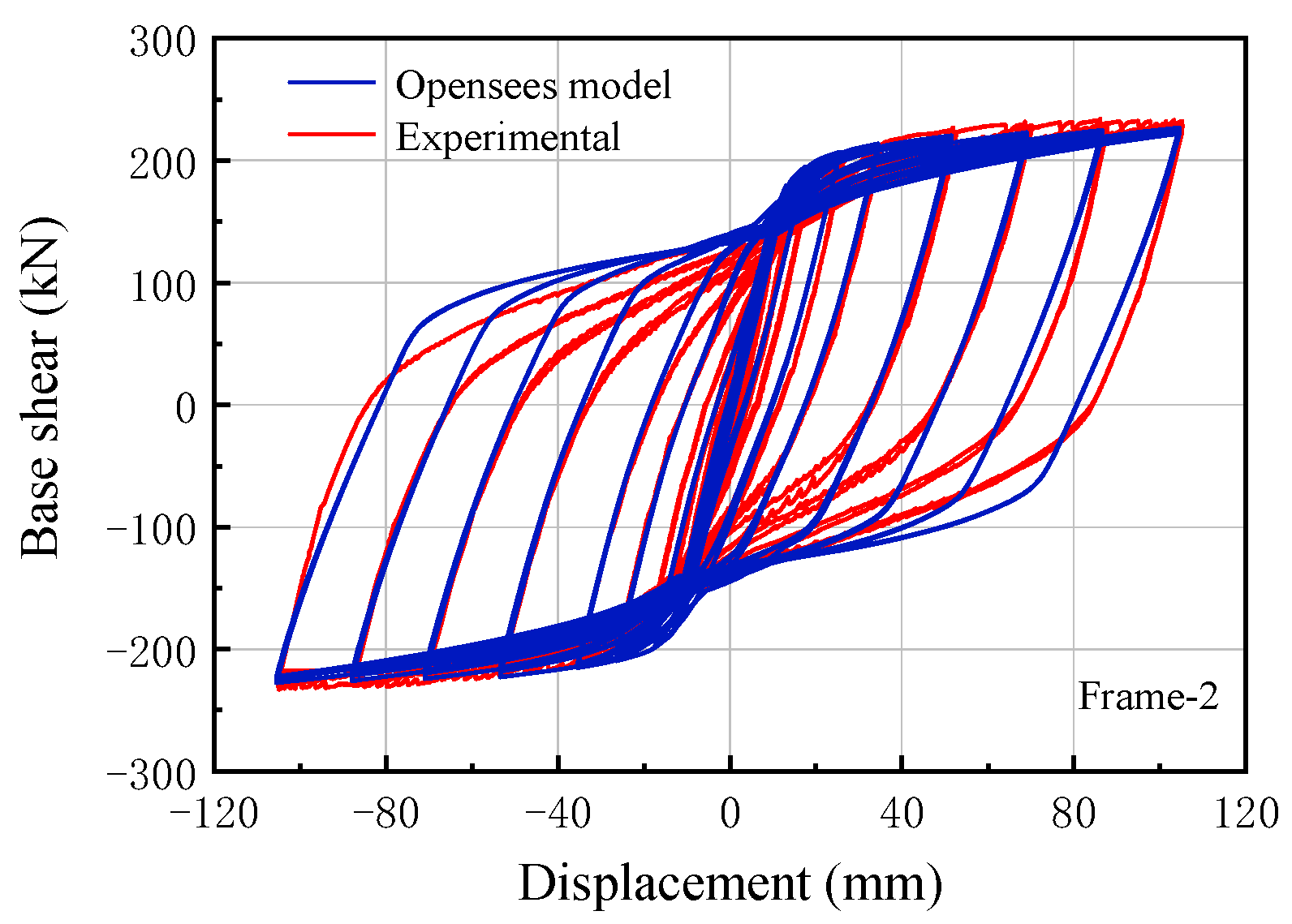
3.2.3. Test Results and Simulation Validation

The deformation modes of Frame-1 and Frame-2 are shown in Figure 9. The hysteresis curves of the two specimens are shown in Figure 10. In the early stage of loading, the specimens were in the elastic stage and a small area was enclosed by the hysteresis curve. When Frame-1 was loaded at a positive displacement of 52.5 mm(0.03 rad), a slight deformation of the flange at the column base was observed. As loading continued, the deformation at the column base became increasingly severe and the maximum bearing capacity reached 239.2 kN. Subsequently, under the same level of cyclic loading, the column base started to buckle and the frame-bearing capacity of the frame was degraded. The test was stopped when the loading reached a negative displacement of 105 mm (0.06 rad). Finally, Frame-1 had significant deformation at the bases of the columns and a slight bending of the beam ends. The buckling patterns of the two column bases of Frame-1 were not identical, resulting in an asymmetric hysteresis curve in the positive and negative directions.
At the initial loading stage, Frame-2 was in the elastic stage. At a positive horizontal displacement of 17.5 mm (0.01 rad), a slight slip rotation of the CPSFCs at the bases of columns was observed; as the loading continued, the slip rotation of the CPSFC became apparent. The test was stopped when the loading reached a negative displacement of 105 mm (0.06 rad). At the end of the loading period, the bearing capacity of Frame-2 tended to stabilize at 230.2 kN. For Frame-2, by the end of the test, it was evident that the cover plate at the flange had deformed significantly in bending and the column itself was not buckled, deformed, or damaged. The brass shims between the cover plates and columns were visibly worn. The comparative tests of Frame-1 and Frame-2 showed that the seismic performance of the steel frame structure with the CPSFC at the column bases was perfect and the damage was concentrated at the friction cover plates. The CPSFC can greatly reduce buckling damage to the columns and result in low or no damage to the main structure. The hysteresis curve of specimen Frame-2 had a slight “pinching” phenomenon; the frictional energy consumption of the column bases was stable and the positive and negative hysteresis curves showed good symmetry.
The hysteresis curves obtained from tests and simulations in OpenSees are shown in Figure 11. The hysteresis curves of test Frame-2 were in general agreement with the simulation, validating the rationality and feasibility of the finite element model for CPSFC. For the following section, the CPSFC was placed at the column bases of a multi-story SMF and built-in continuous column steel moment frame (BCCF) to further investigate.

4. Analysis of Multi-Story Steel Frames

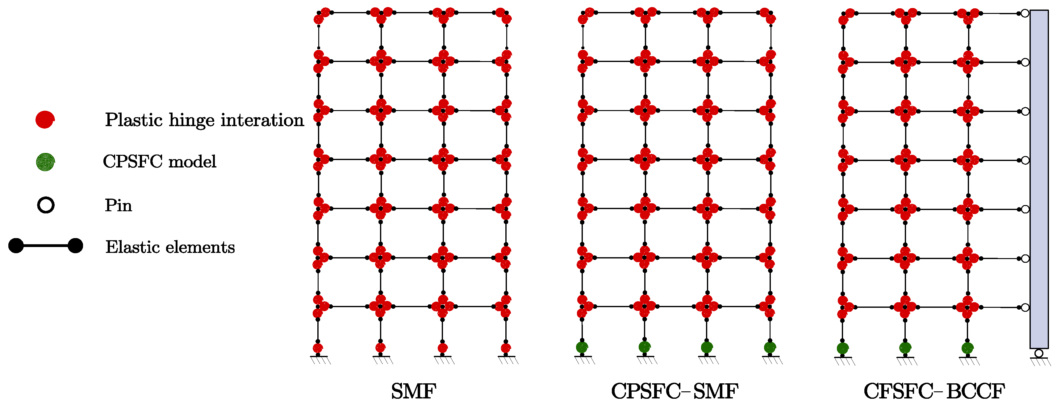
4.1. Establishment of Frames

A three-span, seven-story frame was used for the analysis and calculations. The span was 4 m, and the story heights were all 3.2 m [32]. The frame beams and columns were Q235 steel, and section dimensions are shown in Table 2. The dead and live loads acting on the structure were 600 kg/m2 and 200 kg/m2, respectively. The design seismic group was classified as the second group. According to the Chinese seismic design code [33], the fortification intensity was 8° and the characteristic period of the site was 0.4 s.
A one-bay frame was used for analysis; the CPSFC and BCC were arranged as shown in Figure 12. The benchmark steel moment frame and BCC steel moment frame were created in OpenSees. The CPSFC was added to the column bases of both frames as CPSFC–SMF and CPSFC–BCCF, as shown in Figure 12.
For this paper, OpenSees was used for finite element modeling and non-linear calculations. The finite element model of each frame structure was established using a concentrated plastic hinge approach, that is, the plastic hinge was considered as distributed at the ends of the frame beams and columns. The modified Ibarra–Medina–Krawinkler constitutive model was used for beams and columns to simulate the stiffness and strength deterioration characteristics of the steel, as shown in Figure 13 [34]. The individual mechanical parameters can also be obtained from the regression equations in reference [34]. The elastic beam column element was used to simulate the beams and columns of the frame, and a zero-length element was used to simulate the non-linear behavior of the concentrated plastic hinges at the ends of the beams and columns. The numerical model developed in Section 2.1 was used to simulate the CPSFC force performance at the column bases. To simplify analysis, continuous columns were built up using elastic beam-column elements. The stiffness analysis of the continuous columns will be shown in the following section. The Rayleigh damping ratio for each structure was set at 0.05.

4.2. Stiffness Design of Continuous Columns

To analyze the stiffness of the built-in continuous column, Qu et al. [4] defined the stiffness coefficient α of continuous columns, which can be considered analogously as a simply supported beams. The coefficient α is the ratio of stiffness of the built-in continuous column K c to that of the frame K f . Based on this theory, Li et al. [15] improved the equations, as shown in Equations (9)–(11):
α = K c K f
K c = 8 π 2 E c I c H c 3
K f = ( 2 π T 1 ) 2 M 1
where K f is the first-order vibration stiffness of a steel moment frame, K c is the first-order lateral stiffness of a built-in continuous column hinged to a frame, H c is the height of a continuous column, E c is Young’s modulus, I c is the inertia moment of a built-in continuous column, and M 1 and T 1 are mass and period for the first-order mode, respectively.
A simulation analysis was conducted to investigate the effect of the stiffness coefficient on the plasticity hinge ratio η p and the inter-story displacement concentration factor (DCF). These two parameters can be determined by IDA analysis of the CPSFC–BCC steel frame structure [15]. In this analysis, 22 ground motions in FEMA P695 [35] were introduced, as shown in Figure 14. Additionally, the intensity measure (IM) and damage measure (DM) were also needed. The average spectral acceleration of 5% damping, corresponding to the fundamental period of the frame Sa (T1, 5%), was taken as the ground motion intensity index IM. The maximum inter-story drift ratio was taken as the DM. According to the hunt-and-fill algorithm in the IDA analysis [36], the target IM of the structure can be derived from the DM referring to the maximum inter-story drift ratio (1/50) under different stiffness coefficients. The averaged plasticity hinge ratio η p and DCF of the structure were calculated from 22 ground motions. The calculation formula is Equations (12) and (13).
When η p = 0.5, the deformation pattern of a structure can be considered uniform, achieving the performance objective of adequate energy dissipation in each member [3]; η p can be calculated by Equation (12).
η P = N p N × 100 %
where N p is the number of actual plasticity hinges generated and N is the total number of possible plasticity hinges. The η p reflects the degree of concentration of structural deformation. If η p is low when the elastic–plastic inter-story drift ratio limit (1/50) is reached, it indicates that the structural deformation is concentrated in some structural members. Conversely, under the same case, the greater the value η p is implies that the deformation is uniformly distributed among the elements and the seismic energy on the structure is well dissipated.
The inter-story DCF can be calculated by Equation (13):
D C F = H · θ m a x Δ i
where H is the total height of the structure, θ m a x is the maximum inter-story drift ratio in the structure, and Δ i is the roof drift. The closer DCF is to 1, the inter-story deformation of the structure and the overall energy dissipation are more uniform.
Figure 15 shows the curves of the plasticity hinges’ ratio η P and DCF for CPSFC–BCCF at different stiffness ratios of α . As shown in Figure 15, when α = 0, the continuous column had a weak restraining effect on the structure, with η p at 27%, 29%, and 32% for three structures. As α increased, the η p of CPSFC–BCCF increased non-linearly. When α reached 3.0, the performance target η p = 50% was satisfied. The DCF curve also showed a clear inflection at α = 3.0, where α increased and DCF remained the same. Therefore, α = 3.0 can be taken as a reasonable stiffness ratio for a built-in continuous column.

4.3. Pushover Analysis Results and Discussion

The reasonable stiffness ratio of the CPSFC–BCCF was 3.0, and pushover research was carried out on the seismic performance of each frame. The loading modes used were all inverted triangular loading. As shown in Table 3, no significant change in all order periods of the structure appeared after the CPSFC was arranged in SMF, which indicated that the effect of the CPSCBC on the structural stiffness was insignificant.
As can be seen from Figure 16, the bearing capacity of the CPSFC–SMF was slightly deteriorated compared with the SMF, which was mainly due to the design of the CPSFC; so, the starting slip moment of the CPSFC was lower than the yield moment of the frame column. Owing to the development of structural plasticity, the CPSFC–SMF bearing capacity degradation was lower than that of the SMF. The bearing capacity curves of both eventually intersected at a single point because the addition of the CPSFC to the column bases changed the sequence of the plasticity hinges and damaged the pattern of the structure. No plasticity hinges formed at the column bases, and no bearing capacity degradation occurred. The incorporation of the BCC into the CPSFC–SMF resulted in significant improvement in bearing capacity degradation. Notably, the bearing capacity and lateral stiffness of the CPSFC–BCCF were less than that of the SMF and the CPSFC–SMF because the BCC was hinged to the foundation and frame, but its ability to control inter-story deformation was undeniable.
As can be seen from Figure 17 and Figure 18, the SMF had a large, abrupt change in the lateral displacement between the second and fourth stories. The corresponding plasticity hinge development of the SMF is shown in Figure 17a. The SMF formed plasticity hinges at the bottom of all the columns in the second story and at the top of all the columns in the fourth story; the SMF formed a typical local damage mode. By contrast, the CPSFC–SMF only formed plastic hinges at the top of all the columns at the fourth story; so, the DCF of the CPSFC–SMF was always smaller than the SMF. In addition, as shown in Figure 17c and Figure 18c, after placing BCC in the CPSFC–SMF, the inter-story drift ratio was more uniformly distributed and no abrupt inter-story drift occurred. Plasticity hinges were mainly distributed at the beam ends, which improved the seismic performance of the structure and formed an ideal global collapse mode.
Figure 19 shows the DCF–roof drift ratio curves. The DCF of the CPSFC–BCCF was the smallest, and the initial DCF of the SMF and CPSFC–SMF were equal. As roof drift increased, the structure gradually entered an elasticity–plasticity state and the DCF of the CPSFC–SMF was always lower than that of the SMF. This finding is related to the fact that the CPSFC changed the plasticity hinge sequence and further changed the deformation mode of a structure. Finally, collapse damage occurred to different degrees. With the development of plasticity hinges, the DCF of CPSFC–BCCF gradually increased and then decreased to nearly 1.0 after the plasticity hinges’ ratio reached 50%.

5. Conclusions

This paper proposes a BCCF structure system with the low-damage CPSFC at the column bases. The system integrates the concept of continuous columns’ slip-friction connections to avoid damage at the first story column bases and changes the failure of the steel moment frame. The study was carried out by using experimental and OpenSees simulation methods. The results of a series of studies were as follows:
  • The experimental results showed that the setting of the CPSFCs at the column bases solved the problem of buckling deformation on the columns effectively. The damage dissipation energy of the columns was converted into the frictional dissipation energy of the cover plates such that the main structure showed low damage.
  • An analysis of the stiffness of BCC showed that the vertical, continuous stiffness was crucial to the ability to control structural deformation. As the stiffness ratio of BCC increased to 3.0, the plasticity hinges’ ratio of the CPSFC–BCCF tended to 50%, achieving the desired goal of overall energy dissipation.
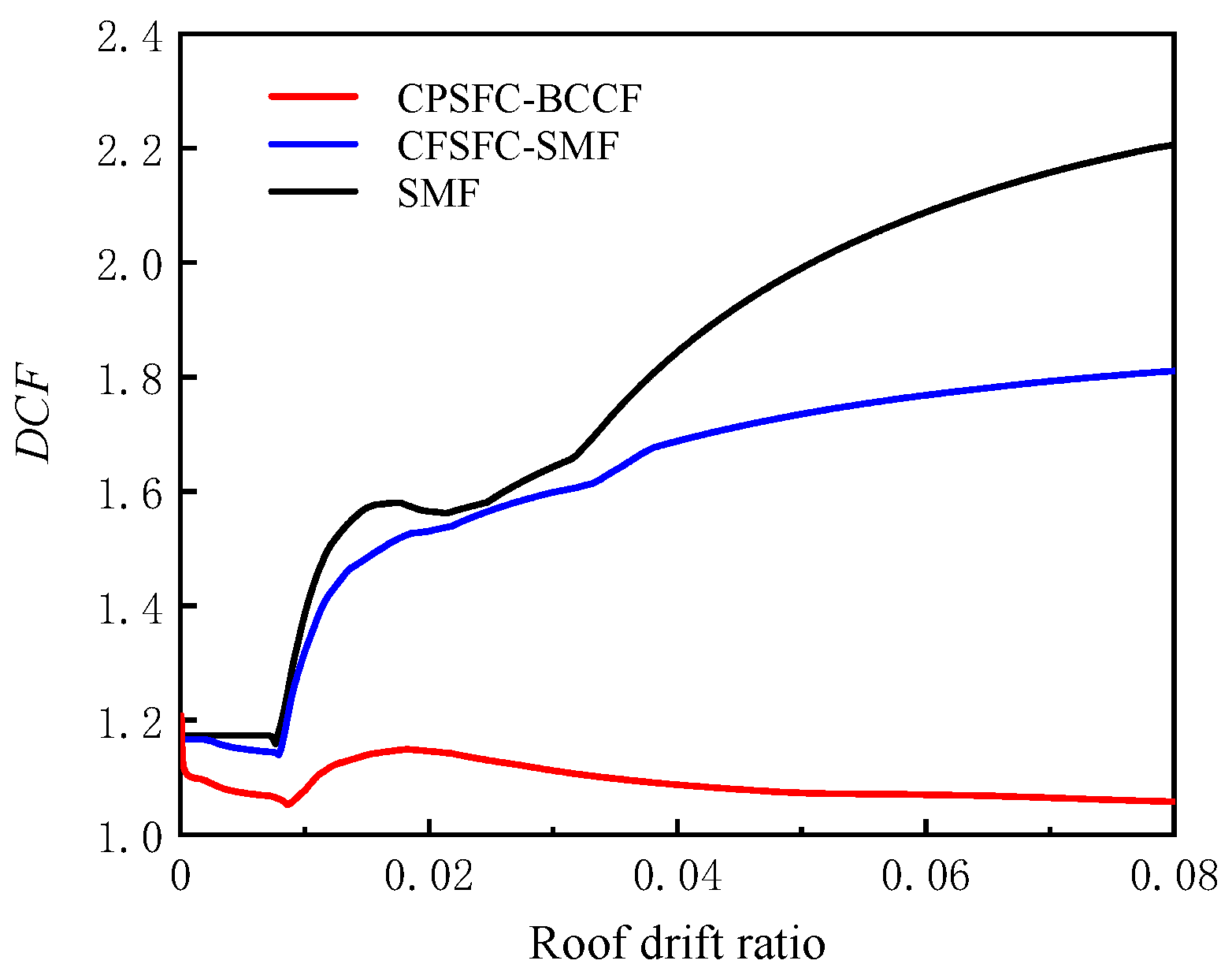
  • The stiffness and strength degradation of steel were considered in the pushover analysis of the seismic performance of multi-story steel frame structures. The comparison of SMF, CPSFC–SMF, and CPSFC–BCCF showed that both CPSFC and BCC were able to improve the ductility and bearing capacity of the structure in the plastic phase.
  • The CPSFC–BCCF frame showed a better seismic performance than the other two types of frames. After the addition of BCC to the CPSFC–SMF, the structure deformed uniformly between stories, facilitating the formation of an ideal global collapse mode. Additionally, CPSFC dissipated a fraction of the seismic energy and thereby prevented the damage of the first story of structures.
  • From a practical point of view, the BCC is relatively easy and feasible to construct and design as it is installed directly within the frame, while the CPSFC is easy to install and remove, enabling the replacement of damaged elements after an earthquake. It is noted that the proposed new CPSFC–BCCF seismic structure is suitable for lower-story assembled steel frame structures.

Author Contributions

Conceptualization, C.L. and A.Z.; methodology, C.L. and B.H.; software R.B.; validation, C.L. and R.B.; formal analysis, C.L.; investigation C.L. and A.Z.; resources, C.L.; data curation, C.L. and R.B.; writing—original draft, R.B.; writing—review and editing, C.L. and B.H.; visualization, R.B.; supervision, C.L. and A.Z.; project administration, C.L.; funding acquisition, C.L. All authors have read and agreed to the published version of the manuscript.

Funding

This work was financially supported by the National Natural Science Foundation of China (No. 51878522).

Data Availability Statement

Data collected from the questionnaire survey and the data analysis results presented in the paper are available from the corresponding author by request.

Conflicts of Interest

The authors declare no potential conflict of interest with respect to the research, authorship, and/or publication of this article.

References

  1. Pampanin, S. Towards the “ultimate earthquake-proof” building: Development of an integrated low-damage system. In Perspectives on European Earthquake Engineering and Seismology; Springer: Cham, Switzerland, 2015; pp. 321–358. [Google Scholar]
  2. Elkady, A.; Lignos, D.G. Improved seismic design and nonlinear modeling recommendations for wide-flange steel columns. J. Struct. Eng. 2018, 144, 04018162. [Google Scholar] [CrossRef]
  3. Lignos, D.G.; Hikino, T.; Matsuoka, Y.; Nakashima, M. Collapse assessment of steel moment frames based on E-defense full-scale shake table collapse tests. J. Struct. Eng. 2013, 139, 120–132. [Google Scholar] [CrossRef]
  4. Qu, Z.; Gong, T.; Wang, X.; Li, Q. Stiffness and Strength Demands for Pin-Supported Walls in Reinforced-Concrete Moment Frames. J. Struct. Eng. 2020, 146, 04020181. [Google Scholar] [CrossRef]
  5. Zaghi, A.E.; Soroushian, S.; Itani, A.; Maragakis, E.M.; Pekcan, G.; Mehrraoufi, M. Impact of column-to-beam strength ratio on the seismic response of steel MRFs. Bull. Earthq. Eng. 2015, 13, 635–652. [Google Scholar] [CrossRef]
  6. Ghorbanzadeh, M.; Khoshnoudia, F. The effect of strong column-weak beam ratio on the collapse behaviour of reinforced concrete moment frames subjected to near-field earthquakes. J. Earthq. Eng. 2022, 26, 4030–4053. [Google Scholar] [CrossRef]
  7. Montuori, R.; Nastri, E.; Piluso, V. Theory of plastic mechanism control: A new approach for the optimization of seismic resistant steel frames. Earthq. Eng. Struct. Dyn. 2022, 51, 3598–3619. [Google Scholar] [CrossRef]
  8. Kamaris, G.S.; Hatzigeorgiou, G.D.; Beskos, D.E. Direct damage controlled seismic design of plane steel degrading frames. Bull. Earthq. Eng. 2015, 13, 587–612. [Google Scholar] [CrossRef]
  9. Ji, X.; Kato, M.; Wang, T.; Hitaka, T.; Nakashima, M. Effect of gravity columns on mitigation of drift concentration for braced frames. J. Constr. Steel Res. 2009, 65, 2148–2156. [Google Scholar] [CrossRef]
  10. Flores, F.; Charney, F.; Lopez-Garcia, D. The influence of gravity column continuity on the seismic performance of special steel moment frame structures. J. Constr. Steel Res. 2016, 118, 217–230. [Google Scholar] [CrossRef] [Green Version]
  11. Zamora, F.S.; Sanchez, J.C.; Qu, B.; Pollino, M. Mitigation of soft-story failures in multi-story steel concentrically braced frames through implementation of stiff rocking cores. In Proceedings of the Structures Congress 2014, Boston, MA, USA, 3–5 April 2014; pp. 2073–2083. [Google Scholar] [CrossRef]
  12. Feng, Y.; Zhang, Z.; Chong, X.; Wu, J.; Meng, S. Elastic displacement spectrum-based design of damage-controlling BRBFs with rocking walls. J. Constr. Steel Res. 2018, 148, 691–706. [Google Scholar] [CrossRef]
  13. Li, Y.; Li, G.; Jiang, J.; Sun, F.F. Modeling of behavior of continuous energy-dissipative steel columns under cyclic loads. J. Earthq. Eng. 2019, 23, 1560–1583. [Google Scholar] [CrossRef]
  14. Li, Y.W.; Li, G.Q.; Sun, F.F.; Jiang, J. Mitigating inter-story drift concentration of concentrically braced steel frames using energy-dissipative columns. J. Earthq. Eng. 2019, 26, 221–239. [Google Scholar] [CrossRef]
  15. Li, C.Y.; Li, D.K.; Bai, R.N.; Chen, Y.Z.; Xu, C.X.; Wu, D.P. Study on Seismic Performance of Steel Frames Equipped with Continuous Columns Based on System Capacity Design Method, Progress in Steel Building Structures. Available online: https://kns.cnki.net/kcms/detail/31.1893.TU.20220804.0912.002.html (accessed on 30 November 2022). (In Chinese).
  16. Falborski, T.; Torres-Rodas, P.; Zareian, F.; Kanvinde, A. Effect of base-connection strength and ductility on the seismic performance of steel moment-resisting frames. J. Struct. Eng. 2020, 146, 04020054. [Google Scholar] [CrossRef]
  17. Takagi, J.; Wada, A. Higher performance seismic structures for advanced cities and societies. Engineering 2019, 5, 184–189. [Google Scholar] [CrossRef]
  18. Inamasu, H.; Kanvinde, M.A.; Lignos, D.G. Seismic stability of wide-flange steel columns interacting with embedded column base connections. J. Struct. Eng. 2019, 145, 04019151. [Google Scholar] [CrossRef]
  19. Yang, T.S.; Popov, E.P. Experimental and Analytical Studies of Steel Connections and Energy Dissipators; Report, No.UCB/EERC-95/13; University of California, Berkeley: Berkeley, CA, USA, 2015. [Google Scholar]
  20. Ramhormozian, S.; Clifton, G.C.; Bergen, B.; White, M. An experimental study on the asymmetric friction connection (AFC) optimum installed bolt tension. In Proceedings of the NZSEE Annual Technical Conference and 15th World Conference on Seismic Isolation, Energy Dissipation and Active Vibration Control of Structures, Wellington, New Zealand, 27–29 April 2017. [Google Scholar]
  21. Gledhill, S.; Sidwell, G.; Khoo, H.H.; Clifton, C. Steel moment frames with sliding hinge joints-lessons learnt during implement. In Proceedings of the Steel Innovations Conference, Christchurch, New Zealand, 21–22 February 2013. [Google Scholar]
  22. Borzouie, J.; MacRae, G.A.; Chase, J.G.; Rodgers, G.W. Experimental studies on cyclic performance of column base strong axis–aligned asymmetric friction connections. J. Struct. Eng. 2016, 142, 04015078. [Google Scholar] [CrossRef]
  23. Benedetto, S.D.; Francavilla, A.B.; Latour, M.; Piluso, V.; Rizzano, G. Experimental response of a large-scale two-storey steel building equipped with low-yielding friction joints. Soil. Dyn. Earthq. Eng. 2022, 152, 107022. [Google Scholar] [CrossRef]
  24. Zhang, A.; Zhang, Y.; Liu, A.; Shao, D.; Li, Q. Performance study of self-centering steel frame with intermediate columns containing friction dampers. Eng. Struct. 2019, 186, 382–398. [Google Scholar] [CrossRef]
  25. Freddi, F.; Dimopoulos, C.A.; Karavasilis, T.L. Rocking damage-free steel column base with friction devices: Design procedure and numerical evaluation. Earthq. Eng. Struct. Dyn. 2017, 46, 2281–2300. [Google Scholar] [CrossRef]
  26. Elettore, E.; Lettieri, A.; Freddi, F.; Latour, M.; Rizzano, G. Performance-based assessment of seismic-resilient steel moment resisting frames equipped with innovative column base connections. Structures 2021, 32, 1646–1664. [Google Scholar] [CrossRef]
  27. Elettore, E.; Freddi, F.; Latour, M.; Rizzano, G. Design and analysis of a seismic resilient steel moment resisting frame equipped with damage-free self-centering column bases. J. Constr. Steel Res. 2021, 179, 106543. [Google Scholar] [CrossRef]
  28. Ramhormozian, S.; Clifton, G.C.; MacRae, G.A. Experimental studies on belleville springs use in the sliding hinge joint connection. J. Const. Steel. Res. 2019, 159, 81–94. [Google Scholar] [CrossRef]
  29. Elkady, A.; Lignos, D.G. Analytical investigation of the cyclic behavior and plastic hinge formation in deep wide-flange steel beam-columns. Bull. Earthq. Eng. 2015, 13, 1097–1118. [Google Scholar] [CrossRef]
  30. GB/T 228.1-2021; Metallic Materials—Tensile Testing—Part 1: Method of Test at Room Temperature. China Quality and Standards Publishing & Media Co., Ltd.: Beijing, China, 2021. (In Chinese)
  31. ANSI/AISC 341-16; Seismic Provisions for Structural Steel Buildings. American Institute of Steel Construction: Chicago, IL, USA, 2016.
  32. Amiri, G.G.; Lahiji, N.P.; Darvishan, E. Effects of in-cycle strength degradation on collapse capacity of steel moment frames. Struct. Des. Tall. Spec. 2014, 23, 801–813. [Google Scholar] [CrossRef]
  33. GB 50011-2010; Standard for Seismic Design of Buildings. Standardization Administration of the People’s Republic of China: Beijing, China, 2015. (In Chinese)
  34. Lignos, D.G.; Hartloper, A.R.; Elkady, A.; Deierlein, G.G. Proposed Updates to the ASCE 41 Nonlinear Modeling Parameters for Wide-Flange Steel Columns in Support of Performance-Based Seismic Engineering. J. Struct. Eng. 2019, 145, 04019083. [Google Scholar] [CrossRef]
  35. Federal Emergency Management Agency (FEMA). Quantification of Building Seismic Performance Factors; FEMA: Washington, DC, USA, 2009. [Google Scholar]
  36. Vamvatsikos, D.; Cornell, C.A. Applied incremental dynamic analysis. Earthq. Spectra 2004, 20, 523–553. [Google Scholar] [CrossRef]
Figure 1. Diagram of the CPSFC–BCCF structural system (BCC is the built-in continuous column).
Buildings 13 00066 g001
Figure 2. Details of the CPSFC.
Buildings 13 00066 g002
Figure 3. Force diagram of the CPSFC.
Buildings 13 00066 g003
Figure 4. M - θ curve of the CPSFC.
Buildings 13 00066 g004
Figure 5. Establishment of the CPSFC: (a) Finite element model of CPSFC in OpenSees; (b) ENT material in OpenSees; (c) Steel02 material in OpenSees.
Buildings 13 00066 g005
Figure 6. Details of specimens: (a) flange of upper steel column; (b) web of upper steel column; (c) cover plates of external flange; (d) flange of lower steel column; (e) web of lower steel column; (f) cover plates of web; (g) cover plates of inner flange.
Buildings 13 00066 g006
Figure 7. Test setup.
Buildings 13 00066 g007
Figure 8. Loading regime.
Buildings 13 00066 g008
Figure 9. Deformation modes of Frame-1 and Frame-2.
Buildings 13 00066 g009
Figure 10. Comparison of hysteresis curves for Frame-1 test and Frame-2.
Buildings 13 00066 g010
Figure 11. Comparison of test and simulation of Frame-2.
Buildings 13 00066 g011
Figure 12. Schematic illustration of finite element models.
Buildings 13 00066 g012
Figure 13. Modified Ibarra–Medina–Krawinkler model.
Buildings 13 00066 g013
Figure 14. Acceleration response spectra (5% damping ratio).
Buildings 13 00066 g014
Figure 15. The stiffness analyses. (a) ηp α curves and (b) DCF α curves.
Buildings 13 00066 g015
Figure 16. Bearing capacity curves.
Buildings 13 00066 g016
Figure 17. Plasticity hinges’ condition.
Buildings 13 00066 g017
Figure 18. Collapse mode.
Buildings 13 00066 g018
Figure 19. DCF–roof drift ratio curves.
Buildings 13 00066 g019
Table 1. Material properties of steel.
Sampling PositionMaterial f y /MPa f u /MPa δ
Flange of steel columnQ235B267.6426.636.0
Web of steel columnQ235B256.4438.730.5
Cover plateQ355B392.9492.430.3
Note: f y , yield strength; f u , ultimate strength; δ , elongation.
Table 2. Section diameters of beams and columns.
StoryEdge ColumnInner ColumnBeam
1240 × 240 × 17 × 10340 × 300 × 22 × 12360 × 170 × 23 × 13
2–3240 × 240 × 17 × 10280 × 280 × 18 × 11360 × 170 × 23 × 13
4200 × 200 × 15 × 9280 × 280 × 18 × 11360 × 170 × 23 × 13
5200 × 200 × 15 × 9240 × 240 × 17 × 10330 × 160 × 13 × 8
6–7200 × 200 × 15 × 9240 × 240 × 17 × 10270 × 135 × 10 × 7
Table 3. Third-order period for each structural model.
TypeT1 (s)T2 (s)T3 (s)
SMF1.2720.4740.271
CPSFC–SMF1.2760.4770.272
CPSFC–BCCF1.4060.4410.197
Disclaimer/Publisher’s Note: The statements, opinions and data contained in all publications are solely those of the individual author(s) and contributor(s) and not of MDPI and/or the editor(s). MDPI and/or the editor(s) disclaim responsibility for any injury to people or property resulting from any ideas, methods, instructions or products referred to in the content.

