1. Introduction
Industrial Revolution: In the development of Additive Manufacturing (AM), robotic tools in the construction industry can be a solution to the high demands placed on construction by the world’s growing population [
1]. In addition to this, the most outstanding merits of today’s modernized construction techniques, such as demands for a higher quality of buildings and higher construction speeds, offer opportunities for increased prefabrication and complex precast projects [
2]. In the Fourth Industrial Revolution (4IR) era, additive manufacturing and robotic fabrication transformed traditional structural manufacturing and industrial practices into modern innovative technology. Among the significant features of the Fourth Industrial Revolution are large-scale machine-to-machine communication, increased automation, improved communication and self-monitoring [
3]. Other aspects of 4IR are cognitive computing, e.g., utilization of machine learning techniques in the evaluation of the construction elements [
4], assigning optimum locations to connections [
5], or structural elements and evaluation of new structural components, e.g., the dry concrete joints [
6].
Robotic Manufacturing: Hence, today, it is essential to employ new techniques and elements and consider the available advantages of the AM methods. Two explicit examples of this process can be: 1. Using robotic concrete printers to replace the traditional methods of constructing the structural elements, e.g., reinforced beams with nonprismatic sections and optimized beam layout instead of typical layouts and sections (additive). 2. Using robotic milling tools for manufacturing the dry connections instead of complex formworks or manual tasks that hinder the practical use of some connections (subtractive).
Subtractive Manufacturing: Computerized Numerical Control (CNC) techniques can be considered as one of the main robot-based subtractive manufacturing methods. The first segmental post-tensioned pedestrian and bicycle bridge utilizing CNC techniques was constructed in 2017 in the Netherlands. In comparison with cast-in-place buildings, the structures produced by AM required less time and cost, considering the scaffolding, formwork and reinforcement processes [
7]. Appropriate dry joints increase the efficiency of the segmental construction, utilising multiproductive tools, e.g., CNC-milled high-precision formworks, match-cast process [
8], grinding technology [
9] and high-pressure water jet cutting, which could appropriately assist the production of perfectly fit dry joints [
10]. The additive and subtractive methods are commonly used for prefabricated structures.
Challenges in Precast Joints: In the entirety of prefabricated structures, the performance of the connections has a crucial role. The typical connections generally have three significant drawbacks, which should be considered in designing new connections: 1. Accidental separation that could occur with no warning in severe loading conditions [
11]. 2. Stress concentration may lead to local or general collapse [
12]. 3. Lack of resistance against all degrees of freedoms, e.g., the bending moment. These connections were not primarily designed for carrying bending moments, present at the end of the elements, and therefore, need further concrete filling into the connection. One of the most common connections in this category is the Corbel connection, which despite its robust resistance against shear load, normally does not have sufficient bending resistance without additional parts, causing a higher bending in the middle of the beam. This joint also has no parts to stop the beam element from falling. In other words, due to the lack of a suitable interlocking mechanism, any little accidental movement may cause the beam to fall. This issue has caused several chain collapses during construction time in the past. To increase the competitiveness of the precast systems, ensure the stability of the entire precast systems under construction and considering the high potential of AM, the construction industry should focus on developing novel details with higher interlocking mechanisms [
13].
New Geometry for Dry Concrete Connections: Hence, efforts to develop dry structural concrete connections, inspired from dry wooden connections and using Ultra-High Performance Concrete (UHPC), were made [
14]. In this context, several achievements for the investigation of “dry wood joints” and for their adaptation to building structures were discussed [
15]. As a result, the method and performance of these connections were analyzed regarding various load types [
16]. Drawing inspiration from carpenter’s joints and advancing the use of high strength fiber reinforced concrete, the research projects were able to manufacture and study novel precise concrete joints [
14], achieving over
of the bending capacity of monolithic elements with the same dimension [
17]. Likewise, The Scarf connection is one of the well-known dry connection geometries whose performance is 55–57% of the load-carrying capacity of the monolithic beam [
18].
Investigation Approaches: A wide range of innovative dry connections numerically and experimentally were evaluated. These studies proved the accuracy and capability of the FE methods in assessing the performance of the dry connections [
19]. In spite of this, numerical (FE) [
20] and experimental studies [
21] were selected to investigate the connections‘ performances with respect to several load types [
22,
23]. These studies proposed efficient precast connections, while demonstrating the ability of the finite element method to simulate the performance of the connections. The investigations discussed the connections‘ performance and displayed the failure types. Abaqus is one of the most frequently used software for operating FE analyses [
24].
Due to the complexity of the calculations and evaluation of these geometries, researchers frequently used the displacement-based design approach. In these studies, several full-size [
25] and
-size scaled experimental studies on connections were reported [
26]. In addition to the geometry and material of the joint, the post-tensioning technique is another important component. The proper uses of nonadherent post-tensioning techniques in these connections could significantly increase the performance of the joints [
27]. The type of prestressed connections discussed in the current study was also considered in a previous study [
19], which investigated different joints designed for beam and column joints using two different test setups. In both studies, the same production technique, such as 3D-printed plastic formwork and identical dimensions, was used to prove the potential of UHPFRC dry joints. Based on these experiences, new types of joints for bending and shear were designed in this study, and two main points were considered in the designs of the new joints as part of the AM technique and 4IR; first, the adaptability of the geometries to the robotic subtractive techniques, and second, the characteristics of the concrete robotic printing technique.
Development Considerations: The mentioned parts can be itemized as follows:
Necessity of studying the application of additive and subtractive robotics in the automated production of structural elements.
Drawbacks of the connections in the precast systems.
High influence of the prestressing technique in improving the capacity of the precast connections.
Ability of the CNC method in the construction of the segmental structural elements (e.g., segmental bridge).
Potentials of the dry connections in transferring forces in comparison with monolithic elements.
The capability of the FE software in simulating experimental tests of the dry connections.
Aim of the Current Study: Based on the available techniques, together with the studies mentioned above, the present study aims to find suitable dry joints with high structural capacity that can be manufactured at a low cost using subtractive robotic techniques. In order to select the suitable joints, the new proposed geometries were evaluated by experimental and numerical studies, while the capabilities of the prestressing technique and the difficulties of their CNC fabrication were considered.
2. Materials and Methods
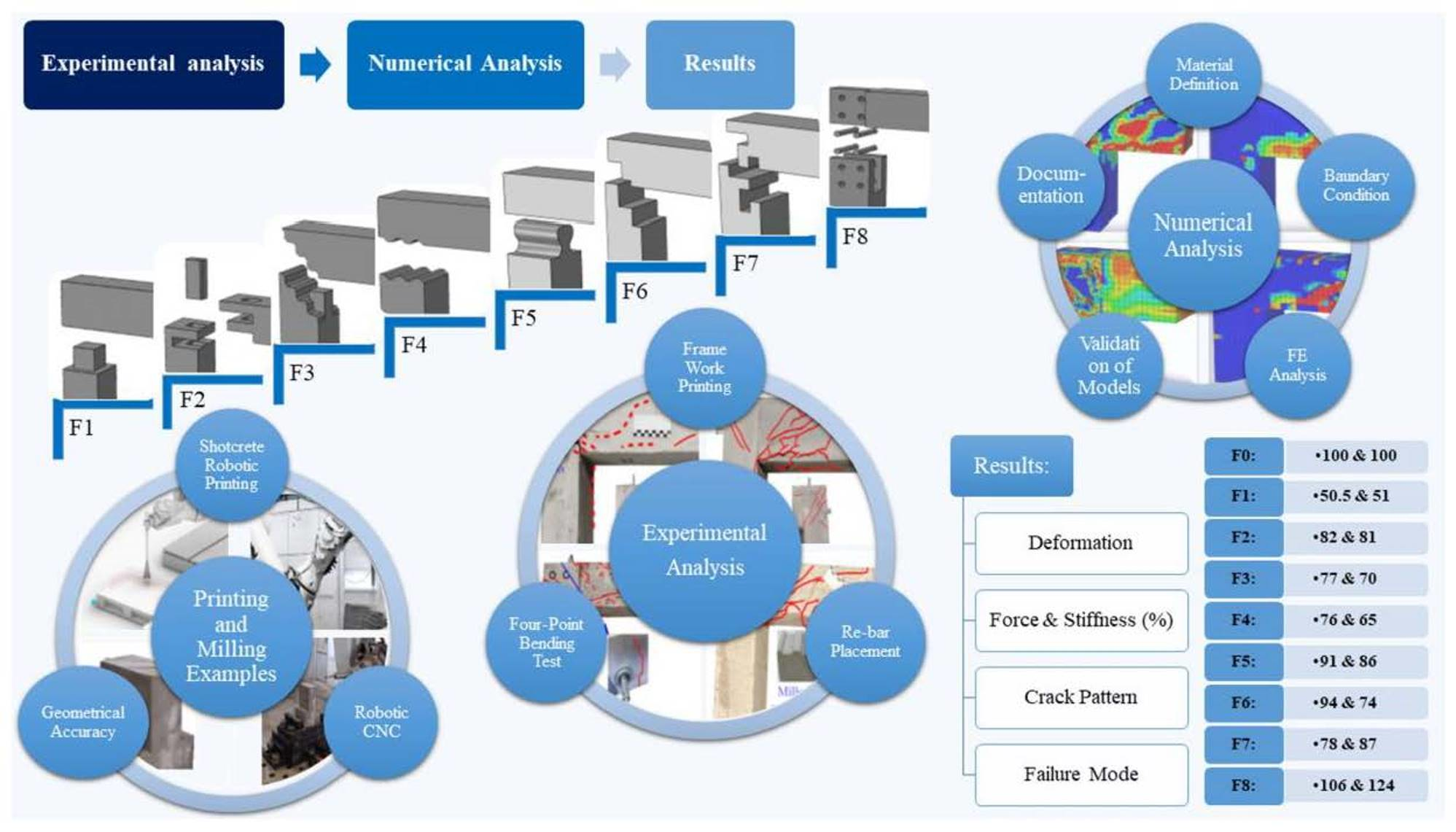
The main objective of this study is to propose and evaluate new geometries for dry connections; moreover, the possibility of automated production of these dry connections was examined. After describing the preparation of the experimental models and the testing techniques, the capacity of the monolithic reference beam and the standard calculations are discussed in the following sections. In the main section, the structural performances of the connections are described. The last section gives an overview of the robotic fabrication technique to produce the proposed precast elements, followed by a general summarization of the elements.
2.1. Development of the Model and Physical Models
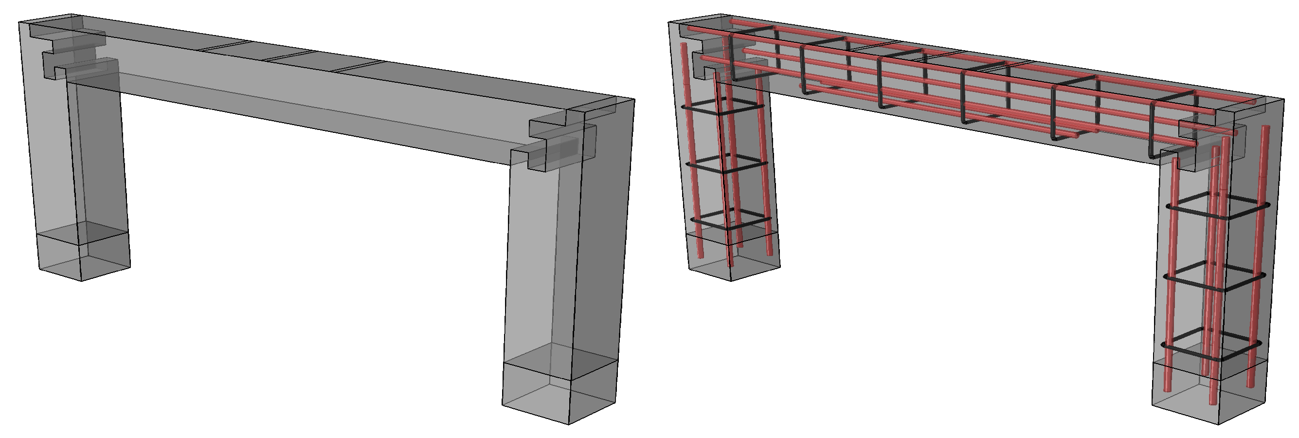
A limited number of other studies introduced and evaluated the performance of the dry concrete connections, mainly under bending loads only. Hence, the present study aimed at developing joint geometries and evaluating their performances under simultaneous bending moment and shear forces as frame connections. Designing new geometries for the dry concrete connections, mainly inspired by wooden and steel connections and their geometrical combinations, was managed in Rhino3D. After initial calculations and engineering evaluations, the extra rebars for each connection part were designed and added to the main rebars (No: 4, ). Then, the numerical analysis of the unreinforced connections indicated the critical zones with high tensile stresses and concrete cracks. Based on the FE results, the geometrical limitations and engineering judgment, the layout of the rebars was designed. It should also be noted that, in addition to the available CNC machines, which can automatedly manufacture rebars with various individual shapes, some companies have started investigating bending the rebars by robotic arms, similarly to what was used in this study for printing the concrete and milling the connections. In Abaqus, each model part was imported with different segments, including 3D connection geometries and rebar layouts.
For the definition of the contact properties, the hard contact by Mechanical Tangential behavior was chosen in the Interaction module of Abaqus, and for the concrete surface-to-surface contact, in addition to the Normal behavior, the friction by penalty method was applied, where 0.3 was classified for the linear friction coefficient [
10,
28].
For the definition of the material parameters of rebars and concrete, three sources were used. First, the manual and catalog of the cement and steel producer, for instance, the properties of the steel material were based on the catalog. Then, the standards and formulas were addressed in the references (B500B). In order to identify the crack pattern, Concrete Damaged Plasticity as the appropriate Property type in Abaqus was used. To calculate and define the parameters, the formulae addressed in the Eurocode [
10], similar to Abaqus (document) and other investigations, were used [
29]. The last sources were a wide range of material experimental tests for each printing processes, managed in DBFL (ITE, TU-Braunschweig, Germany). The used material to pump has low aggregates (Nafufill, MC-Bauchemie Müller, Bottrop, Germany). (Incl:
2.1 Mpa)). The current study is a subproject of a larger project to develop Additive Manufacturing techniques in Construction (AMC).
The rebars in the assembly were located inside the concrete and attached by the Embedded constraint in the Interaction Modules of Abaqus. The initial dimension of the meshes was 10 mm, and mesh types for steel and concrete were 2-node linear 3D truss (T3D2) and 8-node linear brick element with reduced integration Uhr glassing control (C3D8R), respectively. The details of the rebar percentage was mentioned in
Table 1 The supports and the loading parts were placed directly on the surface by cuts over concrete surfaces, without modeling the testing machines. The size of the cuts in the supporting part was 4 cm, measured on the test setups. The section dimensions for the loading surface were 2 cm and did not cause stress concentration or significant local deformation in any models.
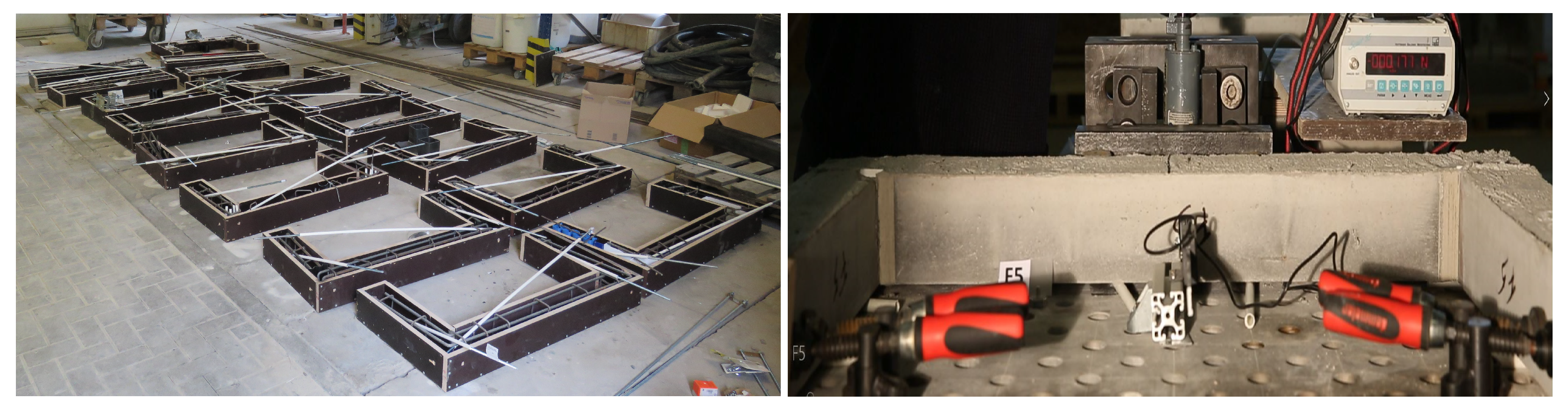
The probable manufacturing deficiencies, such as cavities in the printed material and inaccuracies in geometrical features, could lead to gaps in construction assemblies or fitting of precast parts. Due to simplified casting and avoiding manufacturing factors, plastic printed 3D formworks were used to prepare the physical models to be tested. The manufacturing process of the models for dry connections is described, and the accuracy of their geometries is measured. For the production of the physical models, the mentioned Rhino geometries were sent to the 3D plastic printers (software (Altimaker Cura 4.6)) to make the plastic part of the formwork. The experimental models were managed by casting concrete in wooden–plastic formworks. The main body of the formworks was made of wooden elements and the jointing parts by the 3D printed plastic formworks (thickness: 1 mm).
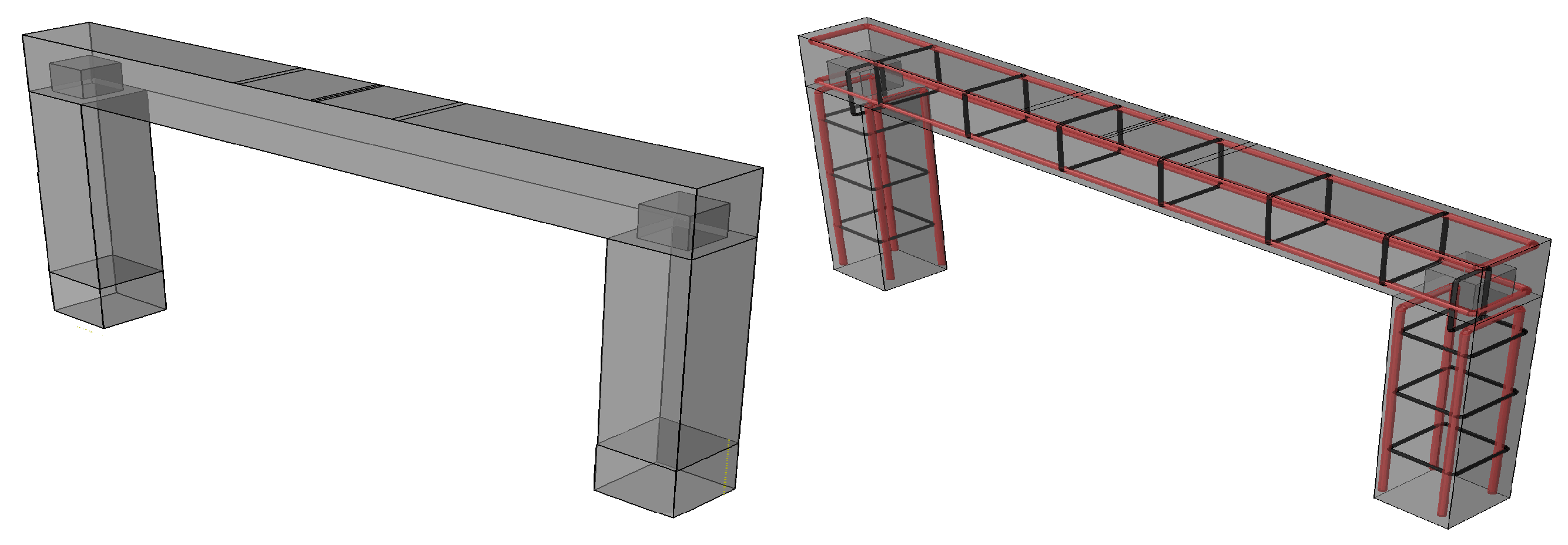
Regarding the small thickness of the plastic formwork (1 mm), deformation may occur when pouring the concrete due to the weight of the fresh concrete. The chosen solution was to pour the concrete on both sides of the formwork simultaneously. Additionally, 10 mm plastic pipes were located in the framework for passing the longitudinal post-tensioning screws, with no connections between the concrete and the screw, as in
Figure 1. The physical tests were carried out 28 days after mixing the concrete, and the same post-tensioning force on the testing day was applied to the nuts at the end of each longitudinal screw, as in
Figure 1.
2.2. Testing Setup and Evaluation of the Monolithic Reference Frame
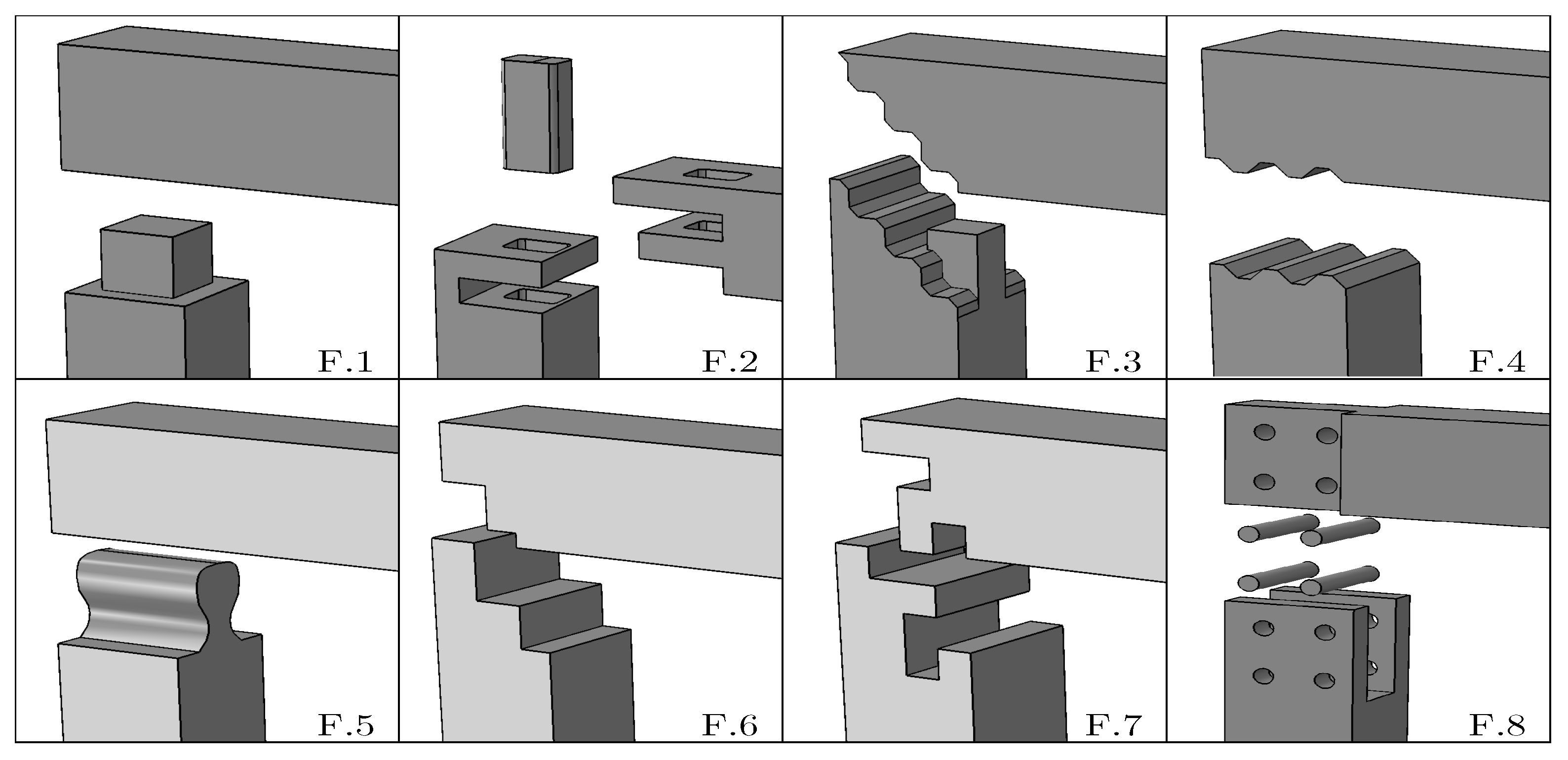
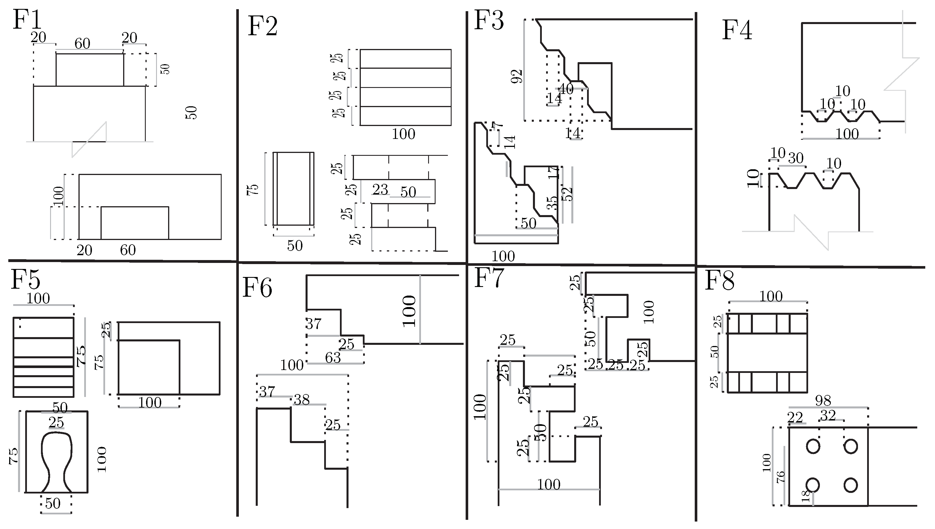
As the first step, some geometries for dry concrete connections are proposed and investigated in this study, dispalyed in
Figure 2. Each model of the proposed geometry is discussed by experimental test and numerical analysis. The selected geometries will be investigated in the next studies to develop the calculation method, the scaling of the geometries and the industrialization of the manufacturing techniques through a series of parametric geometries.
The portal frames were studied under the two point loads, similar to a 4-point bending test, applied on the top beam, as in
Figure 1. This setup, along with the post-tensioning forces, causes shear, axial and bending loads in both directions of the connection. The tests were performed horizontally over a table, in which the direction of the deformation was parallel to the table’s surface, with minimized friction between the table and frame. The bottom sides of the columns had fixed supports. The experimental tests’ main results document the force–deformation and observed cracking patterns. The dimensions of the sections in all tests are 10 × 10 cm. The beam and the side columns lengths are 1 and 0.5 m, respectively. The same type of concrete (shotcrete material
45 MPa) was used in making them under the mentioned robotic technique. The reference monolithic elements and connections had four rebars in their cross-section: two tops and two bottoms (
10 mm).
To avoid the bending failure in the middle of the top beam, additional rebars ( mm) were used in this zone. Based on the type of the material and the diameter of the screw (6 mm) 16 N·m, torque was applied to the nuts at the end of the longitudinal screws, which pass through the beam and column without touching the concrete, causing 10 kN the post-tensioning force at the end of the beams and columns.
The strength of the section was calculated as a general measure of the capacity of the elements and estimated the accuracy of the tests. With reference to the standard ACI and the calculations of the Section Designer of SAP2000, the bending capacity of the section with no compressive rebars and no post-tensioning effect (section
10 mm) is
kN·m. On the other hand, in the reference monolithic frame (shown in
Figure 3) in the presence of the compressive rebars and the post-tensioning load, the bending capacity of the section should be
kN·m. Likewise, regarding the concrete properties (
45 MPa) and the selected stirrups (
6 mm ≃ @12.5 cm), the standard shear capacities (
) are 18 kN. The design standard has a safety factor, (e.g., safety factors (
kN), and the selected distances between the stirrups (12.5 cm) did not follow the considerations of the standard.
The reference beam failed under KN force, applied by the testing machine for the two connections (F). The amount of the load in the failure moment caused kN shear force and kN·mm bending moment. The amount of the forces in comparison with the capacities of the section reveals that, as aimed, the shear force is the main reason for failure. Although the strength of the reference frame is not exactly the same as the calculations of the beam with compressive rebars, the capacity of the tested monolithic frame element is considered the reference value.
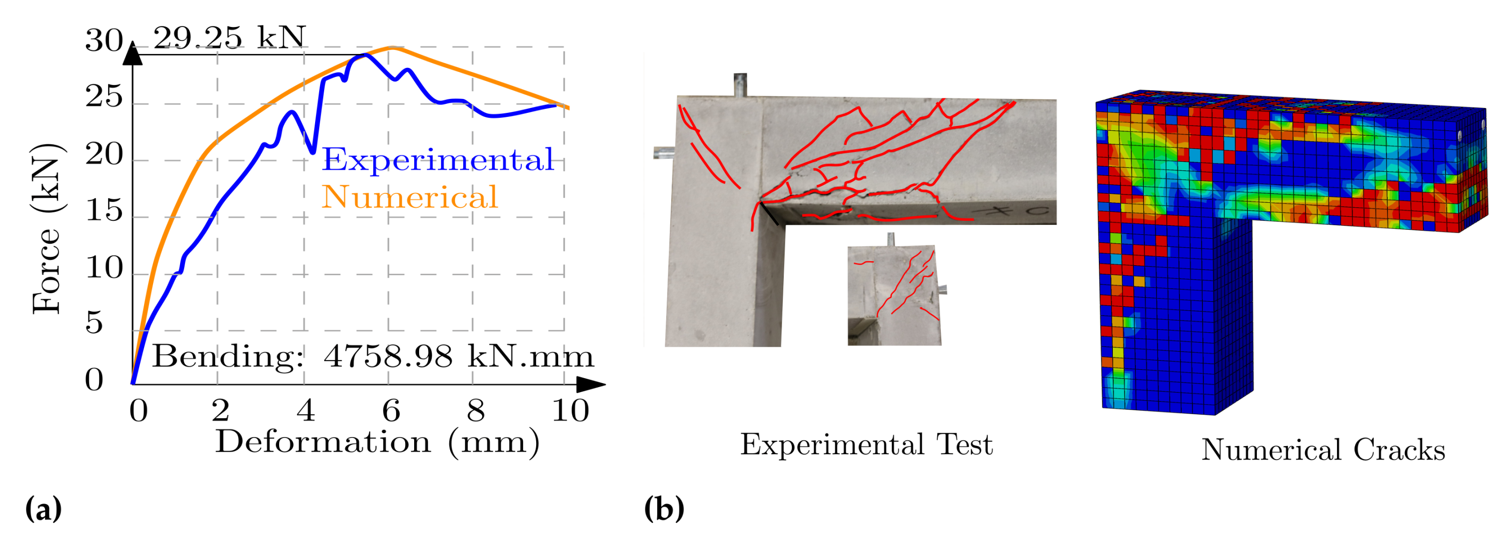
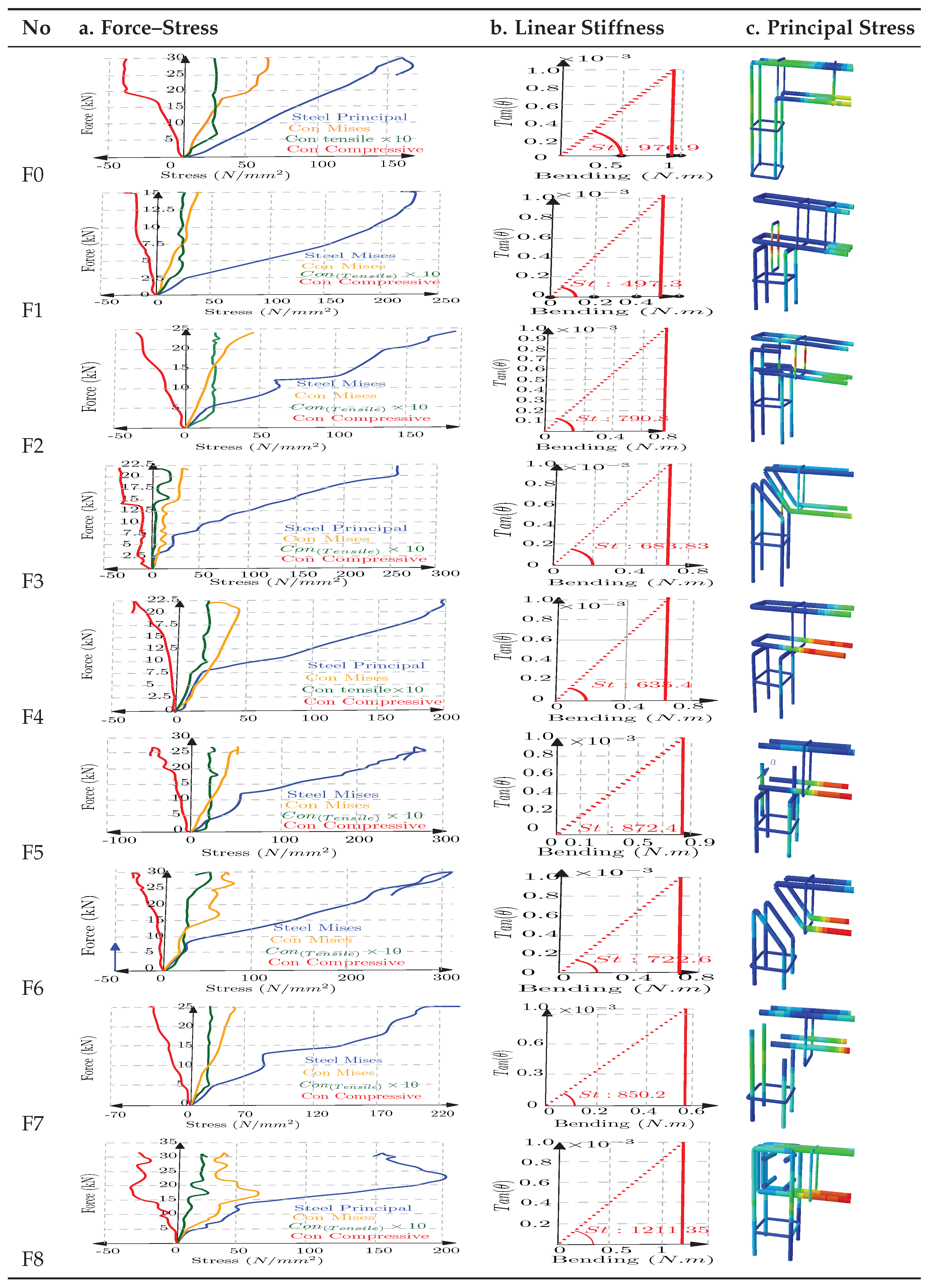
Figure 4 displays the results of experimental and numerical analysis of the frame. The first diagram illustrates the force–deformations from the experimental tests and the numerical analysis results,
Figure 4a. The down diagrams regarding the numerical analysis show the value of stresses in the steel and concrete during the loading process. For better illustration, the amount of concrete tensile stress (×10) is plotted in the same diagrams as the other stresses, as in
Figure A2. The last diagram displays the bending moment and normalized deformation of a point that is 10 cm away from the connection (on the beam) before facing any cracks and damage. The angle of this diagram indicates the linear stiffness of each model, e.g., 976.9 N·m/tag (
), as in
Figure A2. Furthermore, the photos display the crack patterns in experimental and numerical models. The Von Mises and principal stress in the concrete and steel can be seen. The same testing setups were repeated for all geometries, and similar diagrams for each test were plotted, while all testing loads were halved to indicate the force in each connection.
For the tensile behavior, a bilinear approach based on [
30,
31] was considered. For the compressive behavior, ref. [
32] was additionally defined according to Eurocode 1992-1-1. Considering the formulas proposed in the above references, the stress–strain relations were calculated and assigned to Abaqus. Other assigned parameters for damage plasticity can be found in
Table 2.
Likewise, the damages were calculated according to the formula proposed by Wahalathantri. Similarly, the plasticity yield parameters were calculated and assigned according to [
33,
34]. In general, the test results and properties of the concrete are identical to those of previous studies conducted in the same laboratory (DBFL) using the same type of shotcrete material [
35,
36]. For the surface-to-surface bond, “Hard Contact” was chosen, and friction was applied with “Penalty”.
For these simulations, the general static procedure in Abaqus/Standard (2019) was chosen, which, in contrast to dynamic studies, is not directly dependent on the real time but on the loading process. In this context, the forces that occurred in each trial were documented and applied to each FE simulation in a separate diagram. The similarity between the numerical studies and the experimental results confirm the accuracy of the results. Moreover, the standard calculation of the cross-section has almost the same results as the monolithic frame. All experiments were performed under the same conditions and normalized to the reference, which increases the reliability of the results.
The cracks in numerical and experimental evaluations show shear bending as the type of failure. Regarding the stress diagrams of numerical models, the first material failure originates from the concrete tensile failure occurring under 14 kN of the test load, while the compressive failure needed 40 kN (or 20 kN in each joint) to reach the concrete maximum allowed stress,
45 MPa, as in
Figure A2. During the failure moment, the steel stress increased to
of the capacity of the steel.
2.3. Results of Experiments and Numerical Analyses
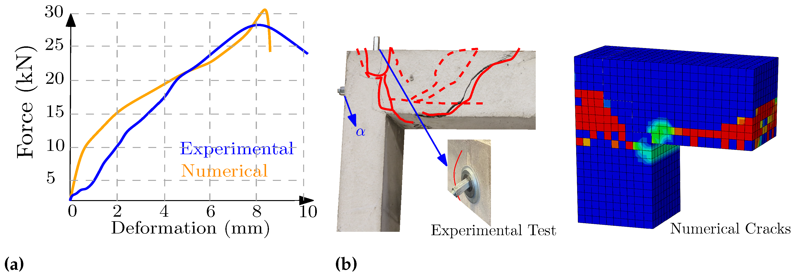
2.3.1. Frame 1 (Cubic-Pin Joint)
The assessment of the first joint type with a cubic geometry (
cm), and with the same dimensions as a beam-to-beam joint, is given in the previous studies [
19] performing under pure bending as
of the monolithic element. This geometry (
Figure 5), which is the improved version of the previous geometries, demonstrated its failure under
of the reference load, at the bending moment and shear force
kN·mm and
kN. Despite using ultra-high-performance concrete in the former studies, this test showed
more robust performance, as shear-bending is the reason for failure, though it has higher strength against shear. The primary failure started from separating the top beam and columns with slight compressive damage in the internal beam–column corner (
), and then, despite the post-tensioning load, the beam and columns from the dry joint parts were separated. Based on the numerical analysis, the first tensile cracks in the connection were experienced on the cubic-positive side of the connection pin, as in
Figure 6. This separation indicated the low value of the axial load applied by the post-tensioning system. In other words, it is anticipated that this joint could perform better in buildings with high compressive column loads.
After forming the tensile cracks in the bottom surface of the cubic geometry (the pin), the rebar located in the center of the pin had higher stress. With 2 mm deformation of the middle of the beam, the pin had 0.6 mm deformation, while the value of the stress of its steel was
of the allowable capacity of the steel, maybe due to looping effects or higher percentages of the rebar in the connection zones. The stiffness criterion was calculated for the normalized deformation of the point over the beam (ST,
Figure 6b), with consideration of the bending amount prior to the appearance of the first crack. The coefficient of stiffness for this geometry is 497.3 N·m/tag (
), which in comparison with the stiffness coefficient of the monolithic beam, i.e., the value 976.9 N·m/tag (
), is considerably low.
The CNC production of the joint’s positive side (pin), employing each robotic sawing or milling tool, is easily possible. A square hole CNC machine, an adaptor for converting the rotary operation of the engine (robot) to maneuver in a rectangular area, can be used to mill the matching pair. Still, in the case of using typical milling tools, fillet curves are required in the corners of the negative side of the joint between the three-planar sides of this negative cubic. This fillet curve should be regarded on the positive side as well. A truncated pyramid instead of a cubic shape can ease the fitting process.
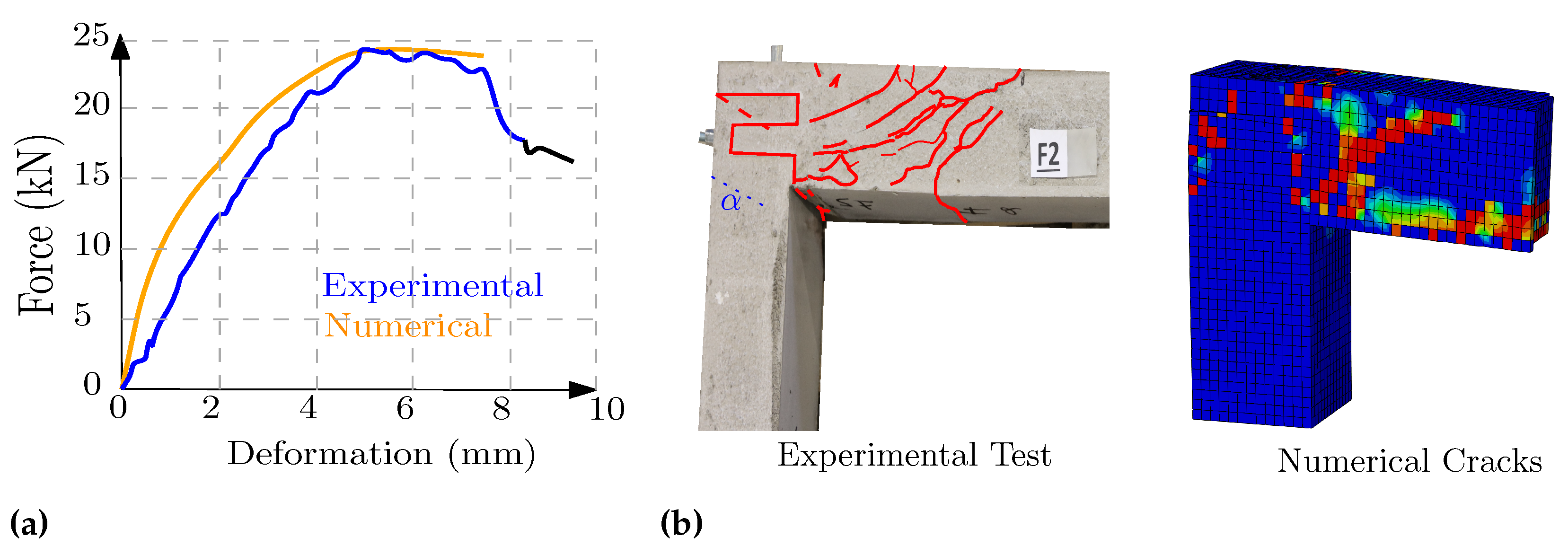
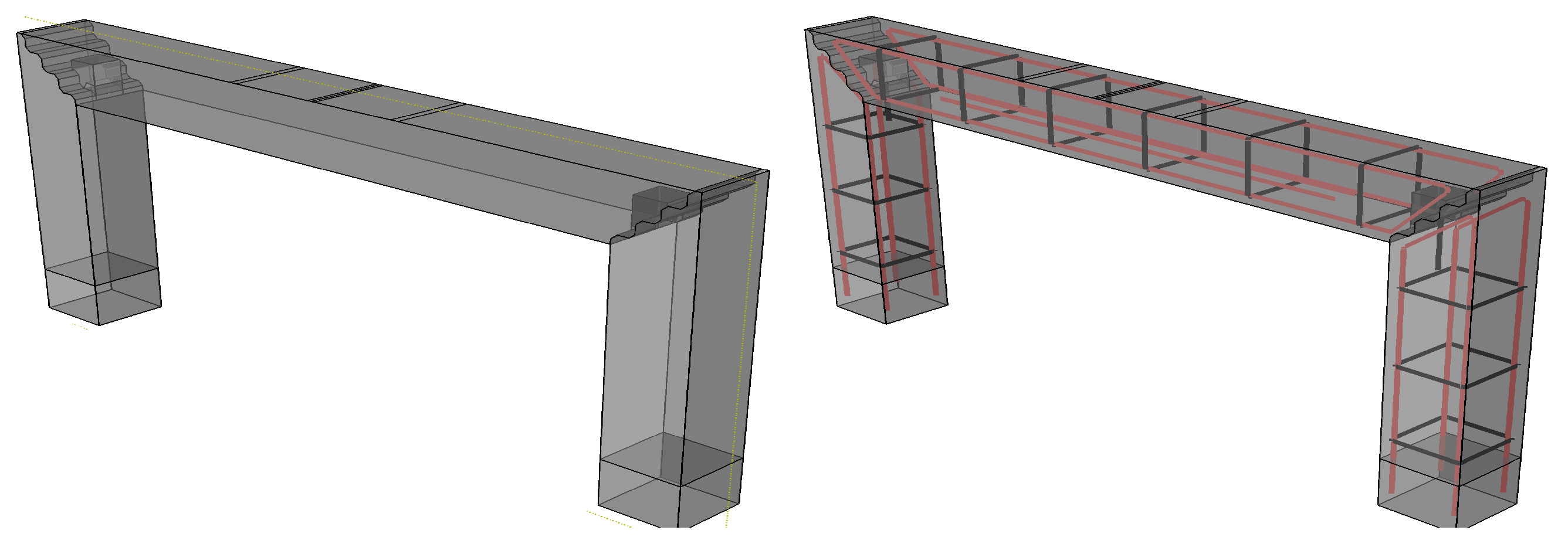
2.3.2. F2: Frame 2 (Paralleled Pined Planes)
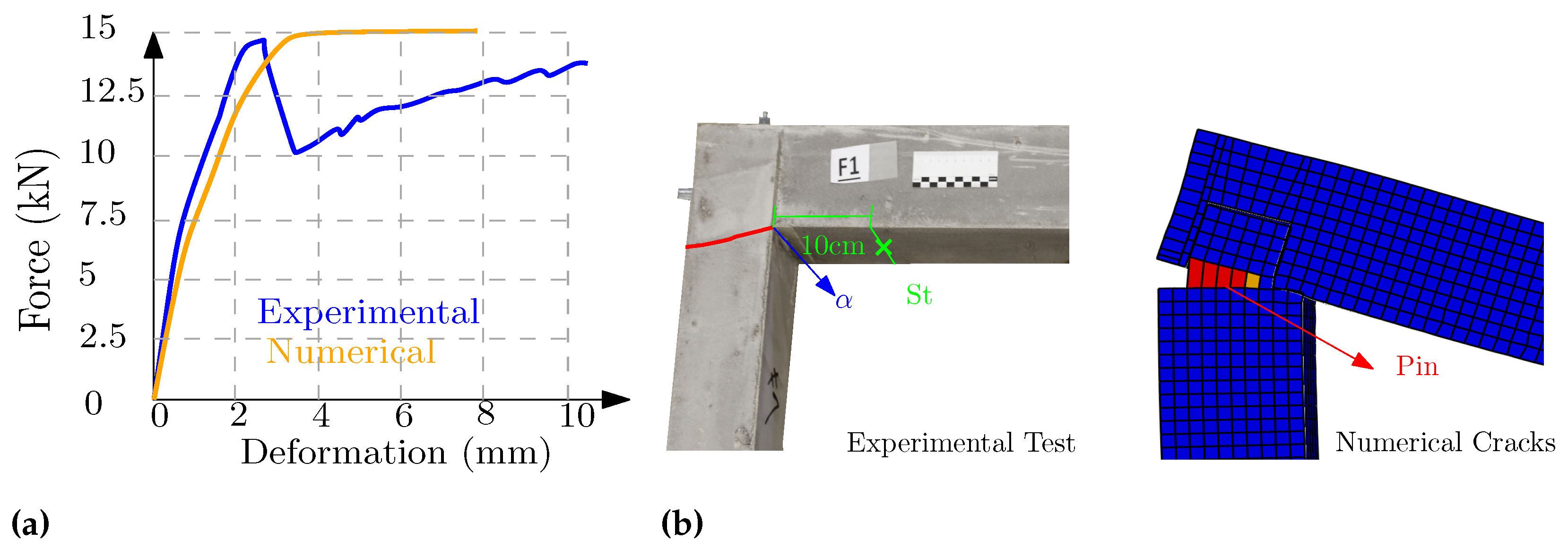
Figure 7 displays this proposed joint inspired by the steel joints and is made from three different parts, including one concrete pin, which should be located after fitting the beam and columns. In this geometry, the initial cracks appeared in the outsides of the columns, lower than the connections (
). Then, the main failure of the joint occurred under the applied load of
48.5 kN from the testing machine; at this moment, the bending moment was equal to 3948.37 kN·mm and the shear force was 4.27 kN, which is 83% of the monolithic section, as in
Figure 8. One of the most critical challenges in designing a dry connection is reducing the tension in the concrete and activating the tensile rebars in the initial loading stages, which happens after the formation of initial cracks in the monolithic beam. In this geometry, and most other geometries inspired by the steel connections, some rebar loops are used around a central pin, transmitting the tensile forces appropriately. The loop-shaped layout causes the geometry to have more active rebars in the initial moments. The key rebars are the rebars in the pin and the last stirrups.
The coefficient of stiffness of this geometry, regarding the bending load and deformation, is N·m/tag (), which is 80% of the capacity of the monolithic element. Based on the numerical analysis, in the failure time, the ratio of the tensile steel and compressive stress of the concrete into their allowable stresses are and , respectively, showing total crash in the concrete. The robotic CNC technique can practically manufacture all three parts of this connection, preferably by saw and milling tools. Fitting such geometry with delicate parts regarding the high friction between the concrete surfaces and the probability of damage is difficult. One solution is using negative tolerances (scale < 1) to the pin, which eases the fitting. Due to the geometry, it should not strongly influence the capacity, similar to steel joints.
2.3.3. Frame 3 (Pinned Sloping Stairs)
In this proposed geometry (
Figure 9), three stairs gradually transmit the shear force of the beam to the top of the column. In addition to the post-tensioning load, one small pin has to resist bending moments applied by the beam, increasing the stiffness. Based on the results of the test, the maximum shear force was
kN, when bending force was equal to 3683 kN·mm. One can conclude that approaching the shear capacity of the full section requires the continuation of the full section of the beam at the beginning of the connections over the columns. This geometry has a small central pin that goes out of the columns to be embedded in the top beam.
Regarding the failure of the geometry (
Figure 10), based on the observed force–deformation films and the numerical simulations during the loading process, following the tiny initial damages on the surfaces between the beam and column, serious damage happened in the columns. The crack patterns were similar to the stair shape, almost parallel to the connection’s geometry, but about 1 cm lower than the connection inside columns (
). Subsequently, the combined shear-bending cracks in the beam were distributed. The highest stress in this model was also experienced in the rebar embedded in the tiny pin, which in the failure moment increased to 255 MPa (
) of the allowable steel stress, as in
Figure A2. The defined stiffness criterion before the cracking time was equal to
of the stiffness of the monolithic reference frame. The proposed geometry uses sloping edges in stairs with no sharp edges; otherwise, the numerical analysis could cause stress concentration.
Likewise, in robotic production, sharp edges during the CNC process mainly get damaged faster, depending on the properties of the concrete. Based on the range of CNC experiences, one solution for reducing the damage in the edges is to move with the milling machine toward the concrete specimen, which means avoiding driving outward and generally finishing the milling in the middle of surfaces and moving up. The most challenging part of milling this geometry is the pin part, especially on the negative side (in the top beam), which needs a square CNC adaptor. Without the adaptor, replacing the sharp edges with a minimum fillet (similar to pins and their negative couples) is essential.
2.3.4. Frame 4 (Trapezoidal Simple Connection)
As the geometry of this trapezoidal connection (
Figure 11) shows, it is not designed for high bending resistance but for quick milling manufacturing and easy fitting. This trapezoidal geometry based on the numerical and physical evaluation loses its stiffness under 44.8 kN load applied by the testing machine, causing 3643.9 kN·mm bending moment and 22.4 kN shear force,
Figure 12. This strength is equal to the
of the capacity of the reference beam. The initial damage in the connection occurred in the first tooth, the most likely region for cracking and separation. The current load distribution might be more similar to a simple beam than a frame, as in
Figure 11.
Many complex geometries can develop higher interlocking and strength in different degrees of freedom; however, applying post-tensioning load and suitable concrete surfaces for good stress distribution can be the most decisive criteria in developing the geometry of dry joints. Although simpler geometries of the connections ease the milling process and may avoid stress concentration for a better post-tensioning application, it can reduce the number of closed degrees of freedom. The robotic production of this geometry was practiced and experienced by rough and finishing milling finger tools. The milling operations for each side of the couple took 20 min and were quickly fitted over each other. The scanning and comparison with the CAD file shows 0.36 mm tolerance regarding the middle top surface.
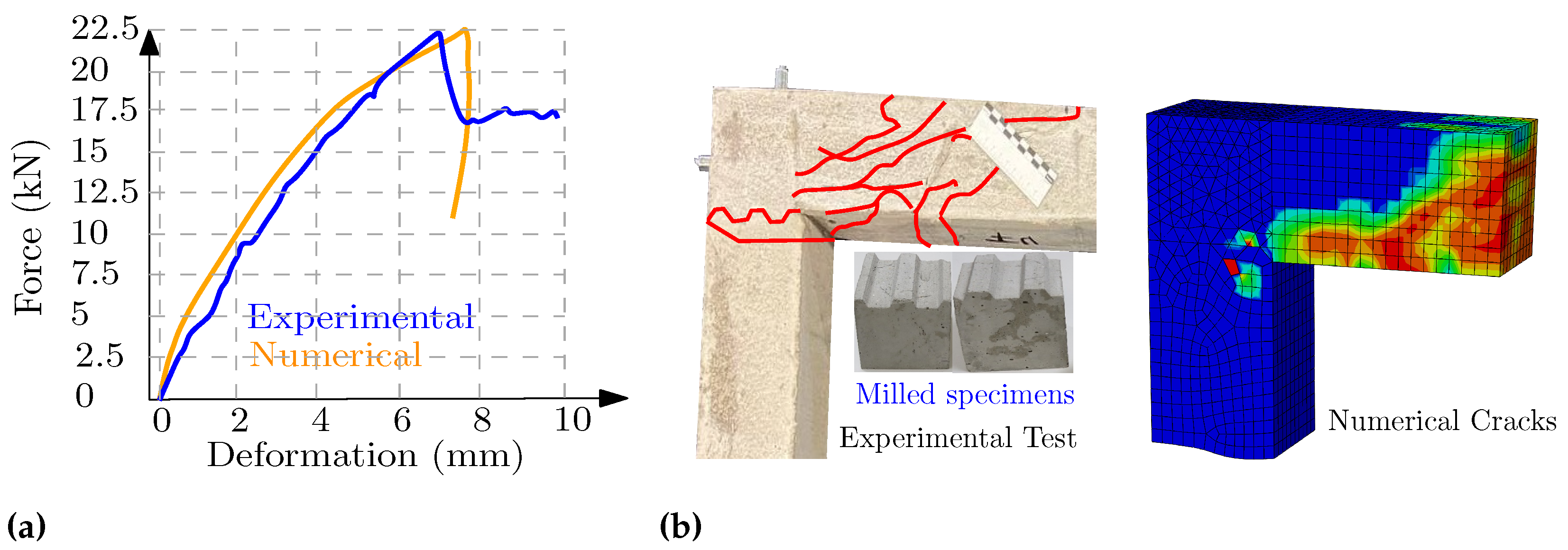
2.3.5. Frame 5 (Carpentry Finger Joint)
The geometry of this connection (
Figure 13) initially inspired by the wooden carpentry joints, was evaluated in the previous studies as a beam-to-beam connection [
19]. Contrary to the previous study, the present testing setup uses the shotcrete printing material (and not UHPFRC), and instead of a beam joint, the geometry is used as the beam–column connection under simultaneous shear and bending forces,
Figure 13. The failure of this joint initiated under bending moment and shear force 4343 kN·mm and 26.7 kN, respectively. This capacity, in comparison with the pin connection (
Section 2.3.1), shows the positive effect of the drop shape versus the cubic pin, while its bending stiffness is 88% of the reference frame.
The drop shape positive (tongue) part is the part that experiences the initial crack in the outer side of the column (
), where the maximum tension is being applied. The load tries to pull this part out, and after the formation of the tensile cracks in the failure time, the concrete compressive stress increases to 90% of the allowable stress due to the stress concentration in the bottom side of the beam (
), when the steel stress raises to 290 N/mm
. Before the initial cracks, the highest steel stress in the connecting zone is on the outer side (
) and the outer rebars of the concrete drop shape pin (
Figure 14,
), showing the importance of the rebars. After the initial cracks in this zone (
), the highest stress occurred in the longitudinal beam’s rebar acting under tension, as in
Figure A2. The rebars’ performance can also be improved by adding hooks to their ends or increasing their lengths to have higher cohesion in the column.
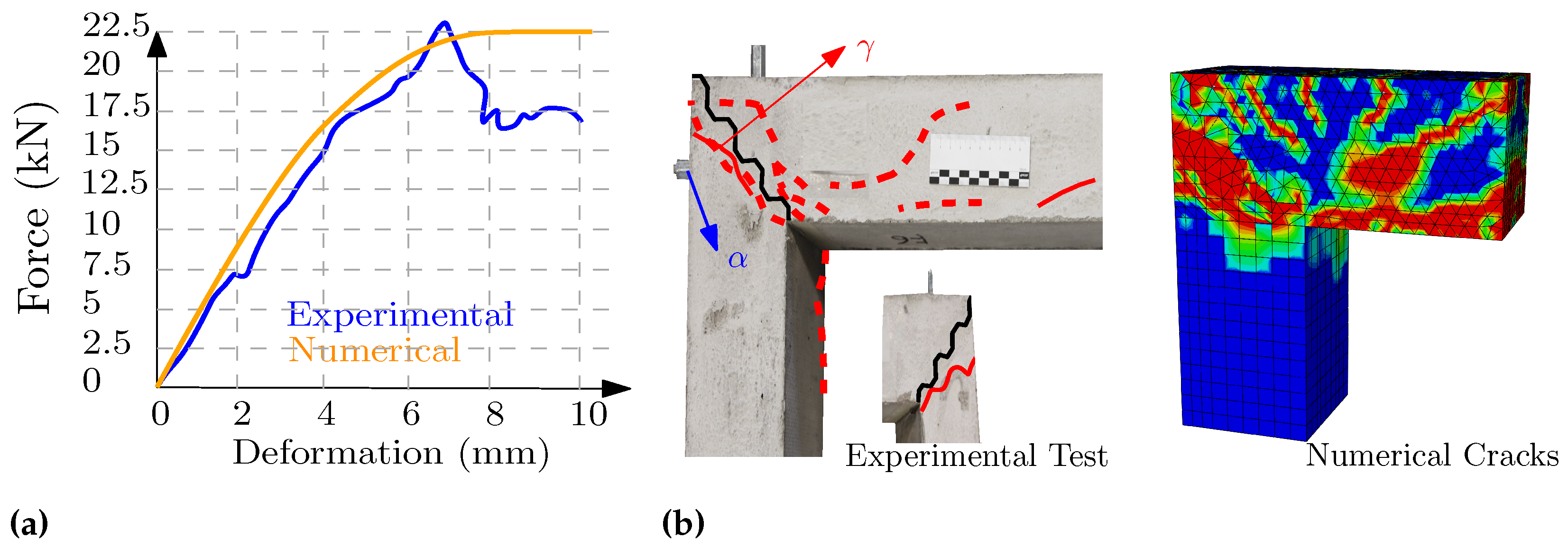
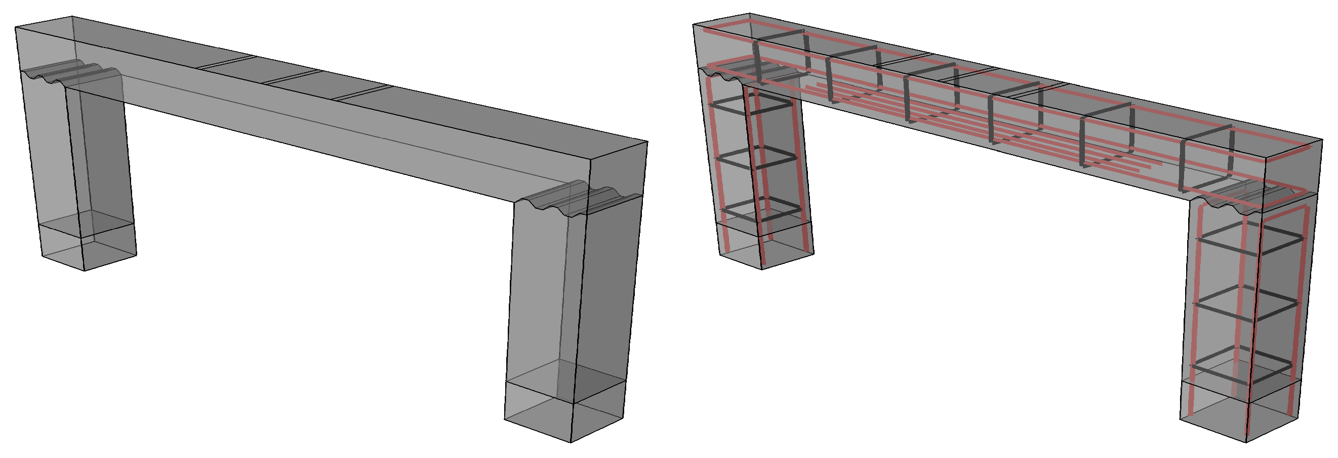
2.3.6. Frame 6 (Stair Joint)
In principle, for developing the dry connections, their capacity and production difficulties should be considered rationally and simultaneously (
Figure 15). This simple geometry showed 27.6 kN and 4489 kN·mm which, regarding its simple production, is high. The geometry is simple and does not have the mid-pin, and in comparison with F3, it could even slightly perform better due to its failure type. The mid-pin was mainly added to improve the bending behavior of the F3, which needed some cutting out from the concrete section (negative-pin), leading to reduced shear capacity, while the bending stiffness is
higher.
F3 is designed for a higher bending/shear ratio and, in other testing steps, performed more robustly. Despite the mentioned
reduction in comparison with F3, the amount of stiffness
N·m/tag (
) in the initial steps is relatively high (
Figure 16). At the weakest part of this joint, the initial cracks appear under tension in the outer sides (
) of the columns, as in
Figure 14. The post-tensioning load applied by the longitudinal screw causes the joint’s thin part on top of the column to move together with the beam and form the first cracks. The stress diagrams of this joint (
Figure A2) display the effect of the tensile failure of the concrete in the mentioned zone (
) with the increasing stress in the rebar under 9 kN force. The damage to the compressive concrete occurred under 25.5 kN, and the stress in steel increased up to 60% of the allowed amount in the failure moment. The maximum stress was experienced initially in the column outside rebars and then in the downside longitudinal rebars and the stirrups of the beam. Based on the experiences and scanning results, generally, the sawing tools, in comparison with milling tools, show a faster process due to large blades and produce more smooth surfaces.
Robotic manufacturing of this geometry took 6 min for each side of the beam; for safety reasons, the robot’s speed was reduced.
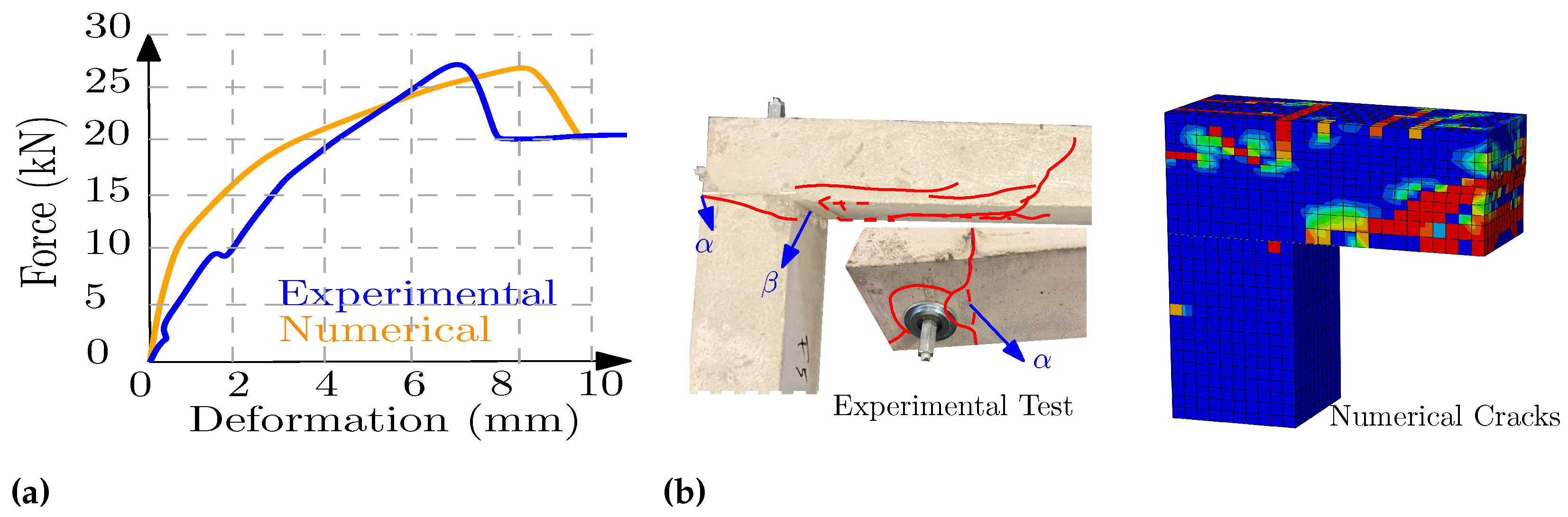
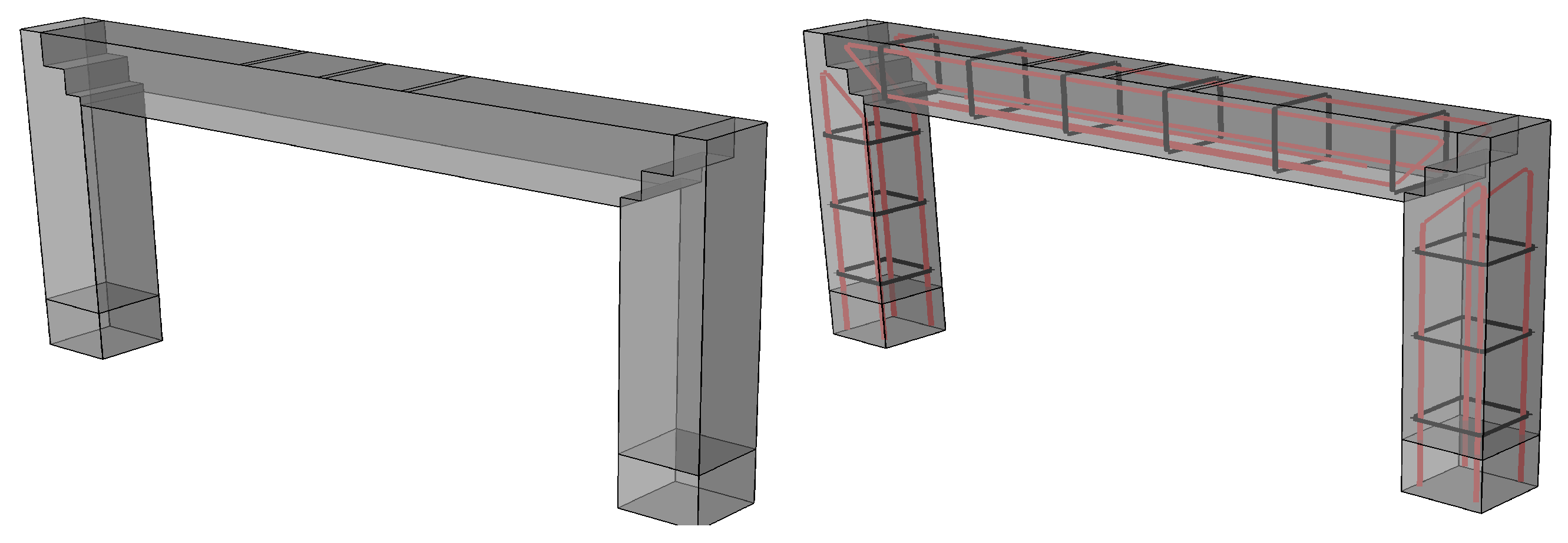
2.3.7. Frame 7 (F-Interlocking)
By making tongues and grooves part, the aim is to increase the bending resistance and the interlocking between beam and column in this geometry, as in
Figure 17. In contrast, the beam keeps
(
) of its cross-section up to the mid-top side of the column, improving the shear capacity. Assessment of this joint showed 3885 kN·mm as the bending capacity and 22.9 kN as the shear force (
Figure 18). The linear stiffness of the joint in the initial loading stages (before any damage or cracks) was 850.2 N·m/tag (
). This high stiffness ratio (
) after the formation of cracks was reduced relatively fast.
The initial concrete failure occurred in the column’s top (outsides) (), similar to most other geometries. With a better reinforcement layout, the capacity can be improved in this zone, e.g., by making some 90 bending curvature at the top end of the rebar to continue inside the tongue shapes (). After the initial cracks, when the connection loses its stiffness, the failure mainly happens in the middle of the top beam. The numerical simulation results also displayed the effect of tensile cracks on increasing the steel stress. Similarly, the stress concentration between the top of the beam and column was also visible based on the numerical results. After of the testing load, the tensile capacity was increased to the maximum amount. On the contrary, the numerical studies did not show any concrete compressive crush during the entire loading process, up to when the geometry increased the amount of steel stress up to of its capacity. Robotic-CNC production of the part of the connection is in the ends of the beam milling or sawing tools and is easily possible (the CNC description). Still, for the other couple (sides), the sharp corner of the lower groove in the column should be replaced by round corners produced by the milling tools.
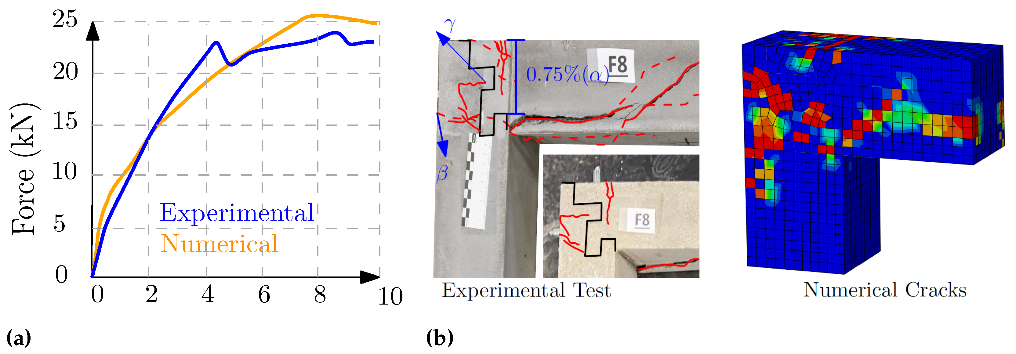
2.3.8. Frame 8 (Concrete Flange Connection)
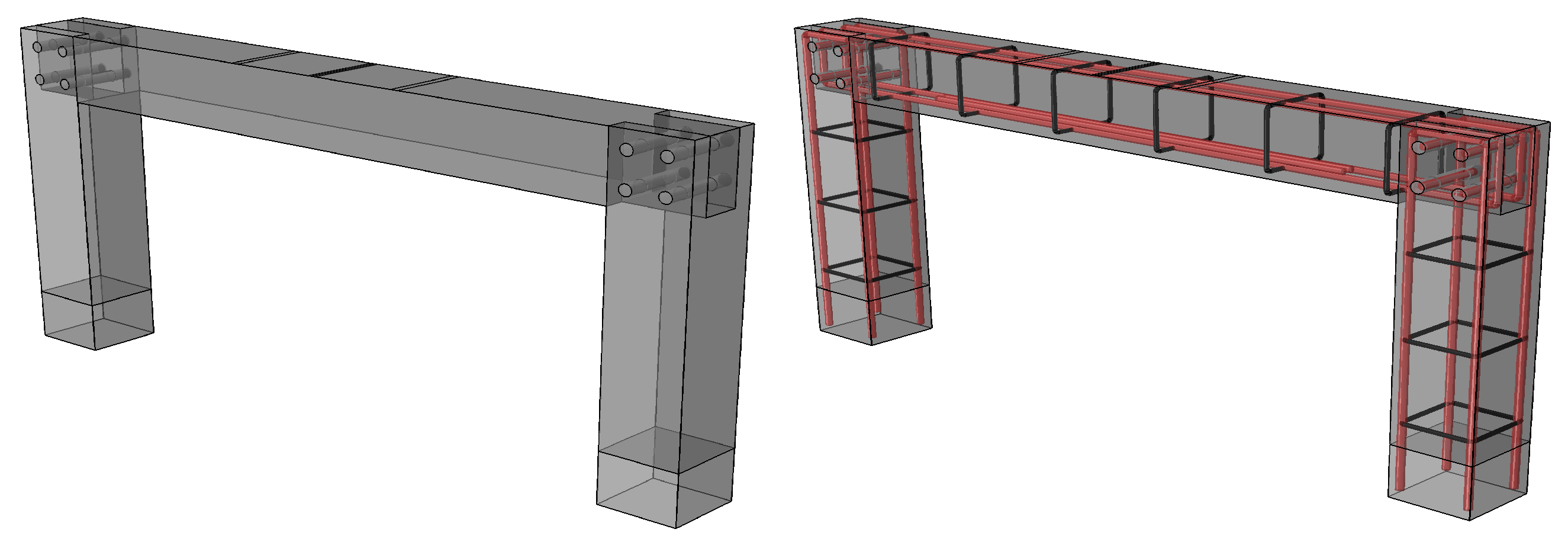
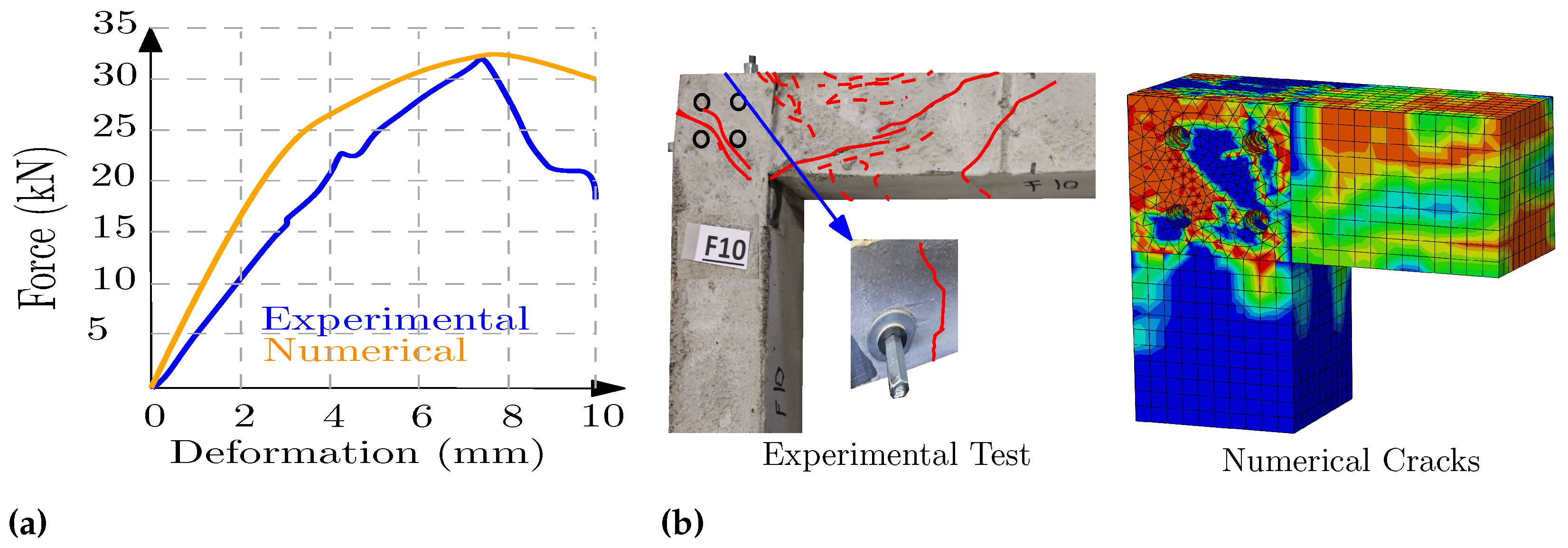
The steel plate bolted connection inspired the geometry of these bolted connections, as in
Figure 19. Based on the evaluations, this inspiration led to the most robust performance among the studied geometries, in which no major failure was experienced up to when the bending and shear forces increased to 5063.9 kN·mm and 31.13 kN, which is
higher than the reference frame, as can be seen in
Figure 20.
This connection, along with its cracks and failure mode developed in experimental and numerical evaluations, displayed a stronger connecting part than the selected beam section. At the same time, this connection did not fail before the top beam developed its maximum capacity. The deformation of the point on the beam, which is 10 cm away from the column in comparison with the monolithic frame, showed more rotational stiffness. The amount of stress in the rebars of the connections shows that, in the initial steps (before failure), the longitudinal rebar of the column, which is on the outer side under tension, is higher than other parts. Still, after the failure, the longitudinal lower rebar of the top beam will be the main rebar. The other positive point about this connection is the possibility of developing a calculation method similar to steel end-plate connections, considering the thickness of the plates, diameters of the pins, etc. Developing such a calculation, which is not easily practical for the other types of dry connections, could lead to the optimum design of the connections. Furthermore, different load combinations for practical applications can be regarded.
Considering the robotic-milling experiences, the robotic production of this geometry is entirely carried out by sawing and drilling tools and, in a relatively short time, is practical. Additionally, both sides of the manufactured connections could easily be fitted together due to their geometry. Besides the connection’s load capacity, the ease of assembling and fitting the joints and the ease of manufacturing are among the significant and critical criteria for selecting a connection. Using this simple fitting joint in practice on construction sites shows its importance. Considering its high capacity, productability, and minimum fitting difficulties, this connection was practically studied using the robotic saw and drilling tools.
3. Additive Manufacturing Technique
One possible scenario for automated manufacturing of these elements includes:
Preparing the rebar layout (e.g., by CNC rebar machine or steel 3D printing (WAAM)).
Printing concrete over the prepared rebars (e.g., robotic shotcrete).
Using robotic CNC to form the dry connections.
This section discusses the robotic printing and CNC process for describing the potential of additive manufacturing techniques in producing the dry concrete connections through some specimens.
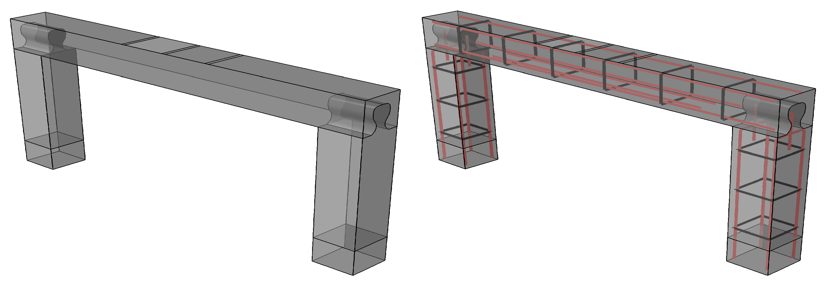
3.1. Robotic Printing Technique for U-Shape Frame
Different concrete printing methods are nowadays available, such as the Particle bed [
37], Extrusion [
38] and Shotcrete printing methods [
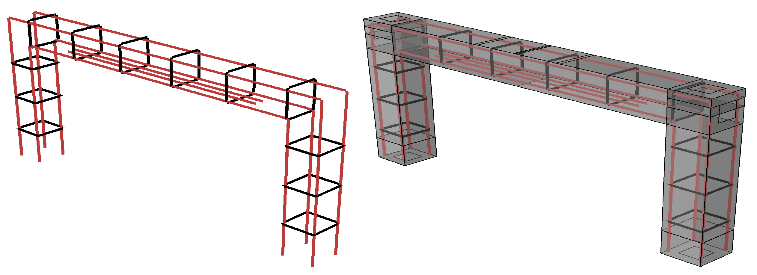
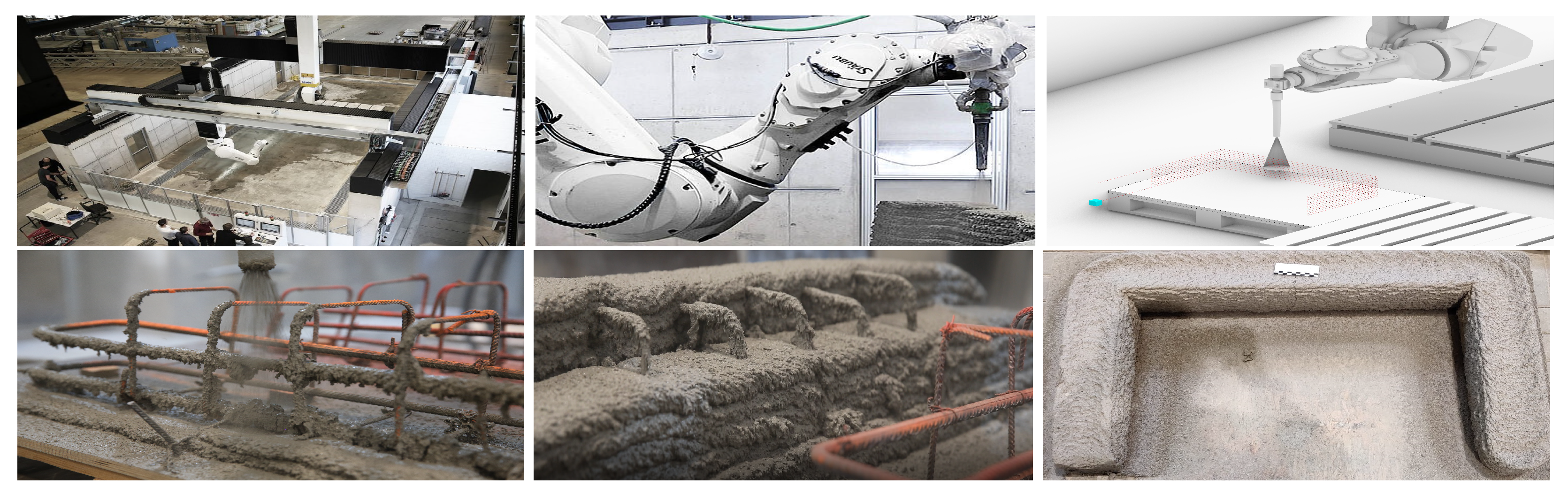
39]. Nonetheless, none of the methods can form a precise reinforced connection geometry. Extortion and shotcrete printing techniques cannot produce fine, precise elements. Furthermore, the quality of particle bed printing material is not high enough to be practically used in the industry, while adding rebars to the particle bed printing to improve the performance of this concrete is not yet practical. Hence, as the most suitable printing technique, the shotcrete method to print over a prepared rebar cage was selected in the present study. Based on the frames’ dimensions, the initial models were made in Rhino.6 for robotic printing. Furthermore, essential parameters, including the number of printing layouts, moving speed, etc., were adjusted. Then, using Grasshopper script, the path planning and robotic G-codes were produced. The nuzzle was attached to the robot’s arm, and during the printing process, a time-dependent pumping process and the related planned path could easily print over and inside the rebar cage in a few minutes using the premixed concrete material.
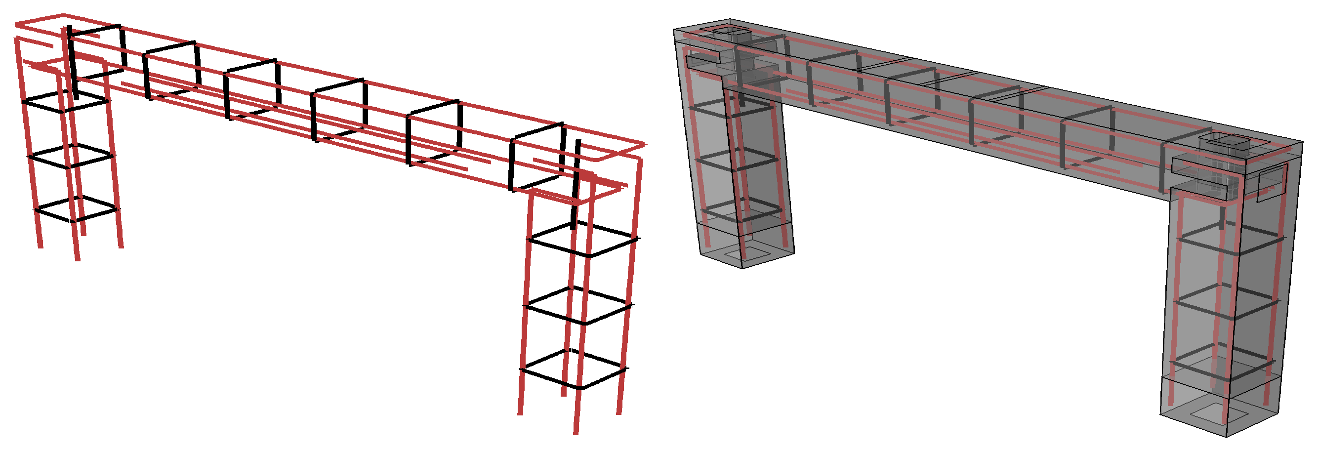
The whole experience was filmed with high-speed cameras; a close look at the film showed concrete cover all over the cages. The selected rebar layout of this U-shape frame was simple and easy to be entirely covered by the concrete by a straightforward path planning, as in
Figure 21. Nevertheless, in the case of complex rebar geometries, alterations in the robotic path planning might be essential, including the coordinates of the path lines, the angle of the nozzle (to shot from different angles) and adjusting the air pressure to print complex geometries and have suitable cohesion between the steel and concrete.
Figure 21 displays the layer-by-layer printing and the final produced U-shape frame. After printing the concrete to accelerate the CNC process and save energy, some cuts over the printed material can be helpful, leading to precise dimensions of the concrete elements, easier CNC clamping and importing exact dimensions to the CNC software. The robot can manage it by soft brushes (or troweling) over the fresh concrete (e.g., within 2 h of concrete casting) or by sawing the concrete (e.g., within a few days). When processing semifresh concrete (green phase), the main issues are less abrasion in tools and energy saving; otherwise, since only the connecting parts need to be clear cut, it can be carried out by the CNC robotic while milling the connections, as rough milling.
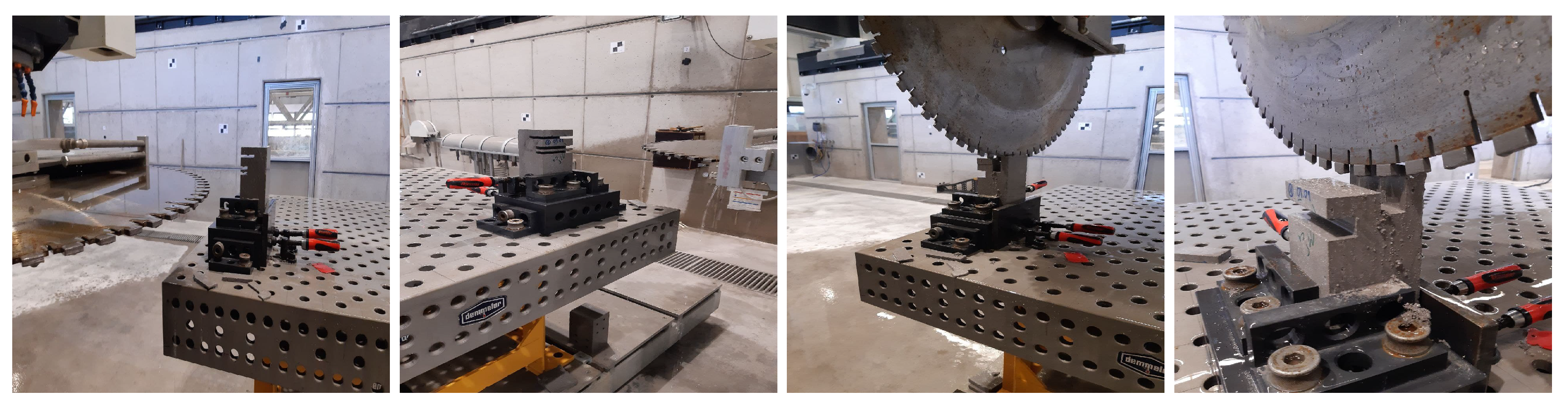
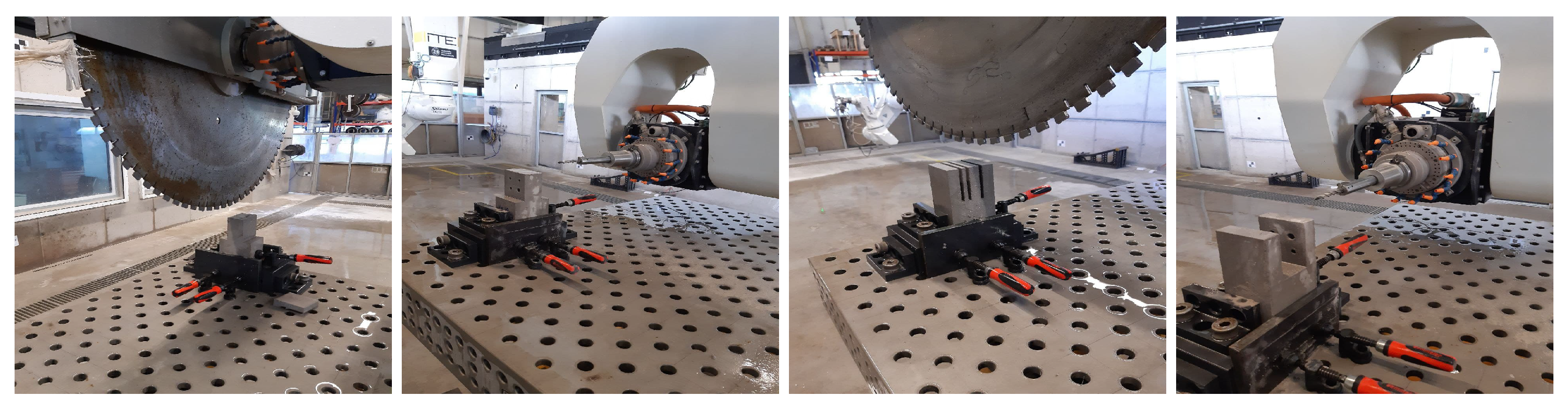
3.2. Robotic Milling/Cutting Technique for Dry Joints
To manage the robotic subtractive process, EasyStone, as a synchronized software (to the robotic lab), after locating the concrete specimens and the clamping table in the lab environment by calibrating their location, can simulate the entire process and make the G-code. In the next step, each part (or surface or edge) of the joints’ geometries is selected individually at the operator’s discretion. The operator assigns the appropriate parameters individually, including the tools and their type, milling steps, tool side, approaching directions and angles. In the final step, after evaluating the collision probability and displaying the CNC process simulation, the software’s simulations (G-codes) were produced and sent to the robot to start the manufacturing. A five-axis portal managed the milling processes in the Digital Building Fabrication Laboratory (DBFL) at the Institute of Structural Design (ITE, TU Braunschweig). Although the dimensions of the manufactured and tested elements are the same (Sec: 10 × 10 cm), due to the geometry, selected tools and G-code, the CNC duration and the number of milling tools differs considerably. For instance, the experienced manufacturing of proposed geometry of F5 (frame specimen no. 5) took 256 min, while F7 and F8 were produced by two tools in 72 and 23 min, respectively (
Figure 22 and
Figure 23 ).
Difficulties of Concrete CNC Technique:
Difficulties encountered in robotic milling have different aspects, including the CNC duration, the financial costs, the limited type of geometries that can be practically manufactured and the accuracy of the final geometries. Considering the milling of hundreds of specimens produced in the same lab of similar size, it can be mentioned that the duration varies from 12 to 256 min for each side of the joint. Accordingly, the milling costs could vary in a wide range. Although it might be an expensive technique in some cases, it should be regarded that this method increases the automation portion of the manufacturing.
The limitations of the geometries for the joints are mainly related to the available tools or suitable space for the robotic arm to approach each edge/side of the joint with a desirable angle. Delicate parts or corners may need specific tools that increase the cost of the process and its duration. For instance, since milling power always comes from swivel motors, making sharp corners (<90) needs engraving tools with specific cutting angles or square hole CNC tools.
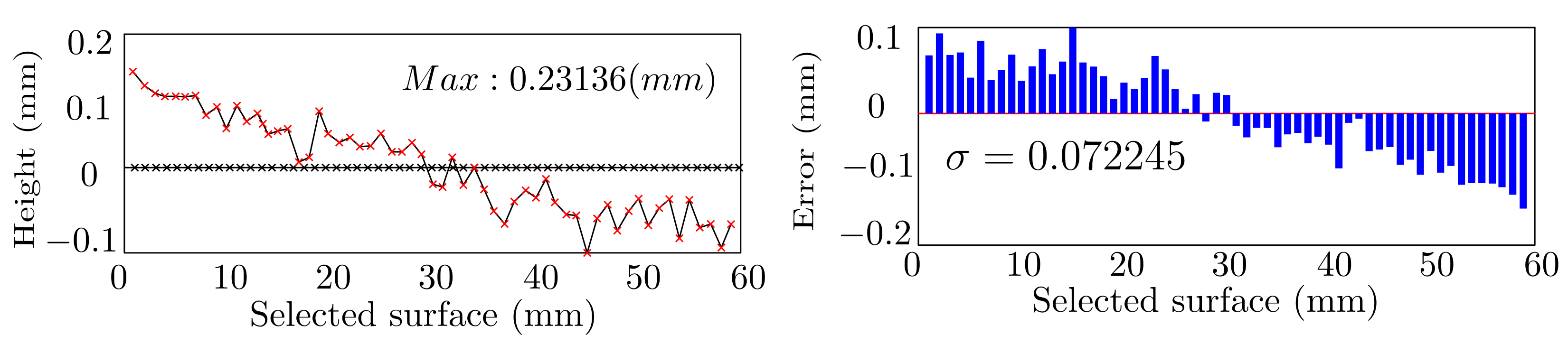
Another main difficulty is the geometrical tolerances in the final manufactured process. In order to measure the accuracy of the mill surface smoothness (2D) and mill geometry (3D), the milled specimens and the initial CAD models were compared together, using two different scanning methods. In the surface evaluation, the geometries of milled elements were scanned by a microlayer scanner, and the scanned points were mapped to the points coming from the CAD file. Comparing these two groups of data utilizing the codes developed in MATLAB could give data about the accuracy of this process. As an example, MATLAB codes produced by overlaying and measuring the differences in Z direction concluded that the standard deviation of the geometrical error is (
: 0.07 mm), while the maximum error amount is 0.23 mm, as in
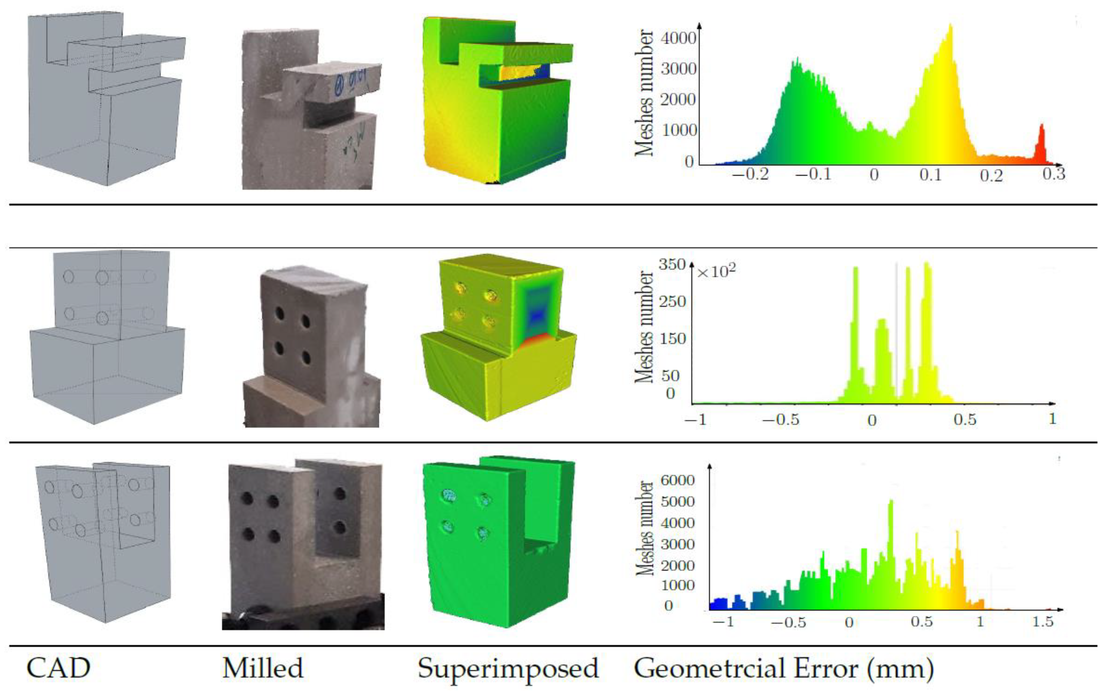
Figure 24. For comparison of the 3D geometries, the software CloudCompare was employed. The 3D scan results with 0.5mm mesh size and the 3D CAD file were located over each other, and the geometrical error was measured. The calculation showed that the range of the maximum errors in them all is between [−1.5 and +1.1 mm], as in
Figure 25. Despite the tolerances, these elements were easily fitted. Various reasons can influence the tolerances:
Complexity of the geometries.
CNC clamping system and concrete material properties.
Calibration of the tools (clamping table).
Fast aging (abrasion) of the tools, etc.
Desirable selection and design of a dry connection can considerably minimize all the mentioned difficulties.
3.3. General Comparison
Table 3 compares the proposed connections regarding the performances during the tests and manufacturing difficulties, where Def: deformation of the top beam under the maximum load; Forces: applied forces by the testing machine to each connection; Forces (KN): real (KN) and the normalized (%) amount of the forces in comparison with the reference-monolithic test; Con
: the loading forces in the first tensile experienced cracking in each connection; Steel
(%): maximum stress of the rebars in the first crackling moment divided by steel capacity B500B (500 N/mm
); Stiff (%): the linear stiffness of joints in comparison with the monolithic element; Steel (max) (%): the relative stress of the steel in the failure moment; Milling time (min): the duration of the milling process in DBFL based on the simulations; and Tool-Type: shows the needed subtractive technique for manufacturing of the joints, Saw (S), Milling (M) and Drilling (D).
As stated, the purpose of this paper is to provide a type of connection that not only connects the elements but also can be made by SM robotic methods. The information in this table enables a comparison between the connections and the reference element.
Among these elements, the force resistance is between 50 and 106 percent of the monolithic element, which is a high value on average. The values of linear stiffness are mainly related to their maximum resting force. F8 connection, unlike concrete joints, was able to considerably activate the tensile rebars. To select an appropriate joint based on
Table 3, F8 has more desirable features, e.g., load capacity and linear stiffness. Inspired by steel joints, this design captured up to
of steel capacity, which in some joints was reduced by
(of steel yield stress). Along with a
increase in the resistance in this connection, it should be noted that the amount of rebars in this connection is
more than the reference frame (
Table 1). Cracking under higher forces (Con
) and higher stress in the monolithic element indicates a more proportionate behavior between the rebar coupling and the compressive concrete, while in the standard references frame, the first crack was experienced under 7 (kN) when a maximum of 9.6 (%) of steel was used, mainly higher than the others. Only in F8 the stress amount in the steel 28 (%) and the demanding load for the first crack is higher than the reference element, indicating the active participation of the rebars in this element (the main task of the rebar).
Another parameter in choosing the desirable connection is the ability to be readily produced by Additive/Subtractive robotic methods. In this regard, based on CNC simulation of them all in the same conditions (DBFL), the subtractive manufacturing times were extracted, which mainly directly relates to the general costs (energy and abrasion of tools). The shortest time belongs to the F6 element, which is 12 min with a saw blade (S), and the most time-consuming element is the F5 element, with 256 min of sawing and grinding time (S/M). This comparison of CNC simulations shows the desirable features of the F8, manufactured in 23 min (M/D). Although this element is not the easiest to build, this basis is generally the best type of connection regarding the strength and difficulty of robotic construction.
Another main point in using the dry joints without additive concrete is the higher possibility of detaching the elements. This point is from considering the necessity of reducing emissions by less concrete production, and using the recycled concrete elements is becoming more important. The easier detachability of connections improves the possibility of reusing the concrete elements and demands appropriate robust connections with lower interlocking degrees. In the following phase of the current study, the selected geometries (e.g., Frame 8) will be evaluated in a range of parametric designs and the possibility of detaching the elements. On the other hand, low interlocking and bending rigidity does not transmit a high bending load to the column, which increases the bending moment in the middle of the top beam. Low interlocking may also lead to the separation of the beam and column with minor local damages and shear failure. Such a failure may cause a chain failure, as already happened frequently in the precast structures, especially during construction. For evaluation of detectability, two points will be initially regarded: creep and shrinkage. These two points will be regarded in different geometries and printed concrete material.
4. Conclusions
The present study proposes and evaluates eight new geometries of the dry concrete joints numerically and experimentally under bending moment and shear force as beam–column connections in U-shape plane portal frames. While most other studies consider the bending performance of these connections, this study aims at developing joints with high shear resistance that can carry considerable bending moments. All proposed geometries are cast in a framework made of wood and 3D-printed plastic. Then, after 28 days, the frames were tested experimentally. Furthermore, this article relies on today’s facilities to demonstrate the possibility of the automated production of new structural geometries to advance new structural systems. In this regard, concrete printing and operating robotic milling/sawing, which is a part of the additive manufacturing technique and the fourth industrial generation, manufactured a number of these joints to describe the process and prove their potential.
The maximum and minimum load capacities compared with the reference beam belong to Frame 8 and Frame 1, with corresponding 106% and 50% of the load capacities of the reference beam.
The level of stress in the repeat bars of these connections can increase to 300 MPa, but no failure of the steel was observed in any geometry.
Similar to normal concrete elements (beams), tensile failure of the concrete was the main reason for failure.
Despite the difficulties inherent in CNC robotics, it can produce various robust dry connections while maximizing automation and eliminating the need for formwork.
The initial stiffness of the connections (before cracking) averages of the monolithic element.
Some dry connections can be practically used as structural elements due to the low difficulty of robotic fabrication, high precision in the fabricated geometry and high structural capacity,
Most geometries must be milled in addition to sawing, which can be more costly in terms of time and money.
The main objective of the study was to discuss the potential of the subtraction technique and to propose possible geometries for dry connections. The subsequent investigations up to the practical application of the discussed geometries and techniques should be considered in a further step from a design and manufacturing point of view. 1. One of the presented geometries has to be selected for further investigations. For example, Frame 8 can be selected due to its remarkable performance, less dependence on geometry accuracy and relatively fast and simple fabrication process. 2. Parametric studies should be carried out. In Frame 8, the dimensions of the pins and the thickness of the thin parallel parts in different scales must be changed. 3. The capacity of the selected connection in relation to another type of force (e.g., torsion, shear and bending in other directions) must be studied. 4. The results of the parametric studies in the different steps, together with the known standard calculation methods, should lead to a tested calculation method, a geometry such as Frame 8, which is easily practicable. After the development of the calculations and structural considerations, the manufacturing technology should be developed. Automated manufacturing depends primarily on the individually selected platform and tools (e.g., robots). Nevertheless, the following issues should be studied: 1. Increasing the accuracy of the manufactured geometry. 2. Minimizing the cost, including the cost of tools (increasing the duration of use) and energy consumption. One of the issues that should be studied in this case is to find the optimal time to make the joints before the high strength of the concrete, for example, one day after the CNC. Due to some time-dependent effects, such as shrinkage, the geometrical changes should be measured at early CNC and taken into account by some differences in the initial CNC models to obtain a suitable geometry after shrinkage.


