
Investigation of Intermediate-Height Horizontal Brace Forces under Horizontal and Vertical Loads including Random Initial Imperfections

Abstract
:1. Introduction
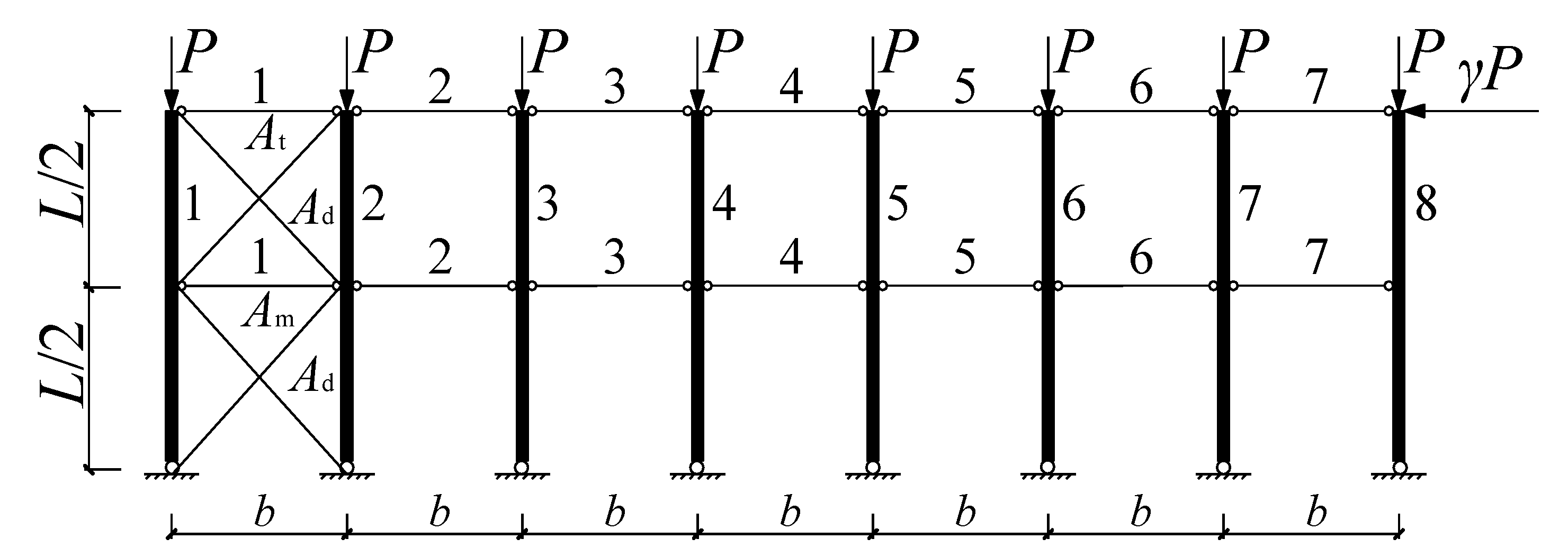
2. Parametric Design and Analytical Model
3. Random Combination of Initial Imperfections
3.1. The Monte Carlo Method
3.2. Probability Model of Initial Imperfections
3.3. Equations for Random Initial Imperfection
4. Numerical Analysis by the Monte Carlo Method
4.1. Numerical Model
4.2. Random Sampling of Initial Imperfections
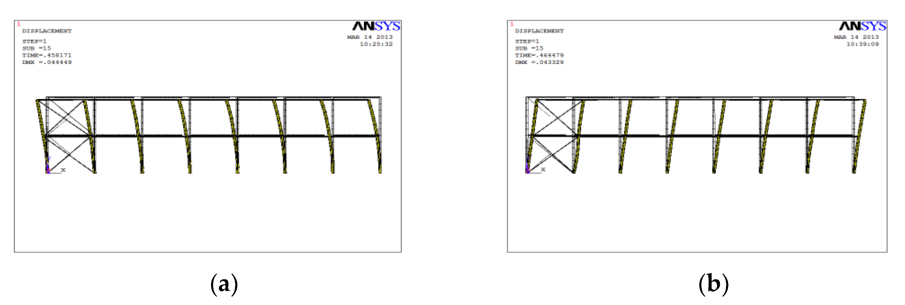
4.3. Numerical Analysis
5. Effect of Horizontal Load Combinations on Intermediate-height Horizontal Brace Forces
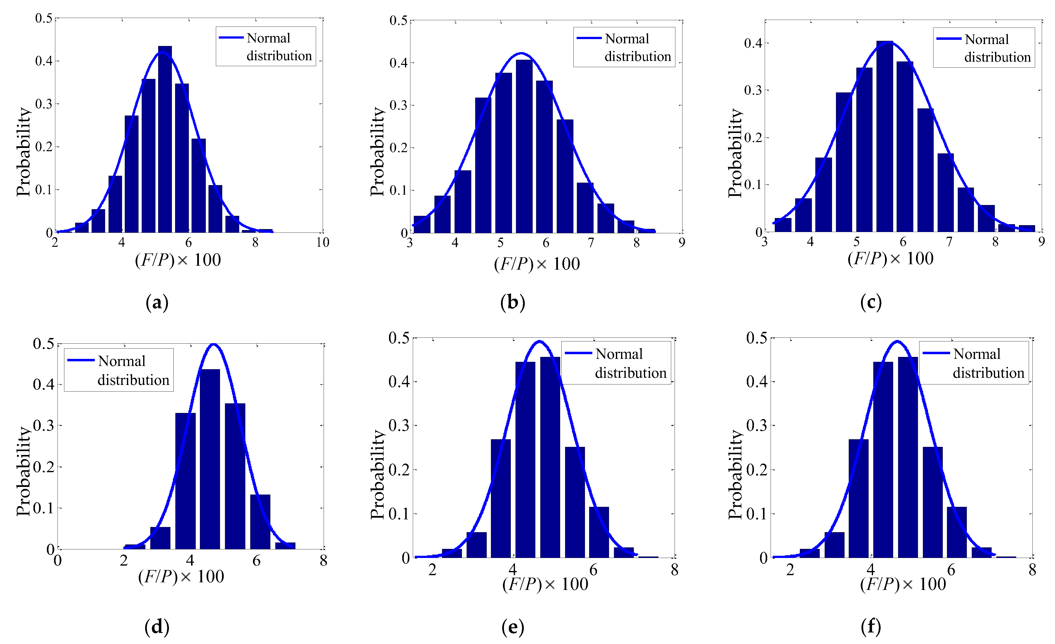
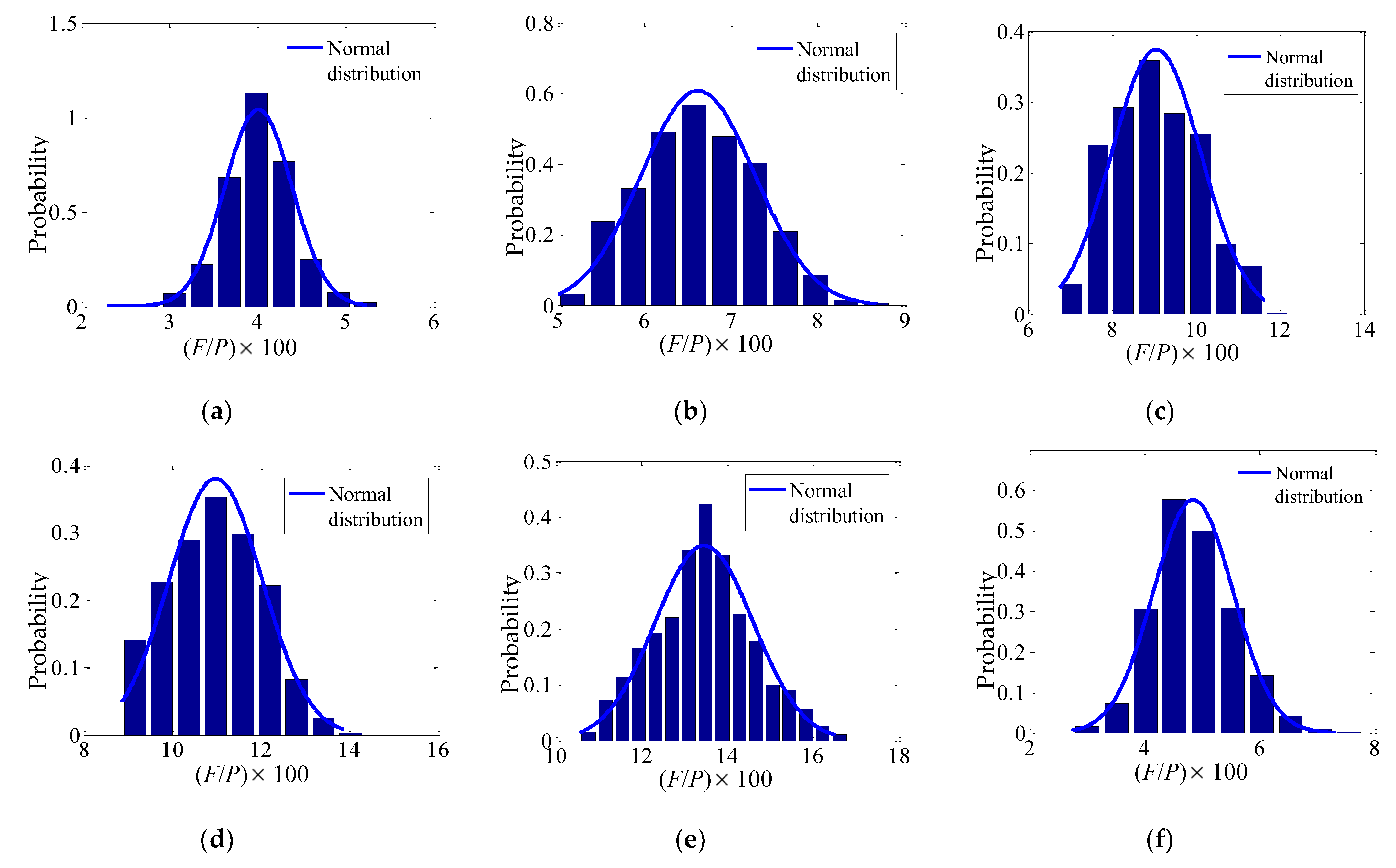
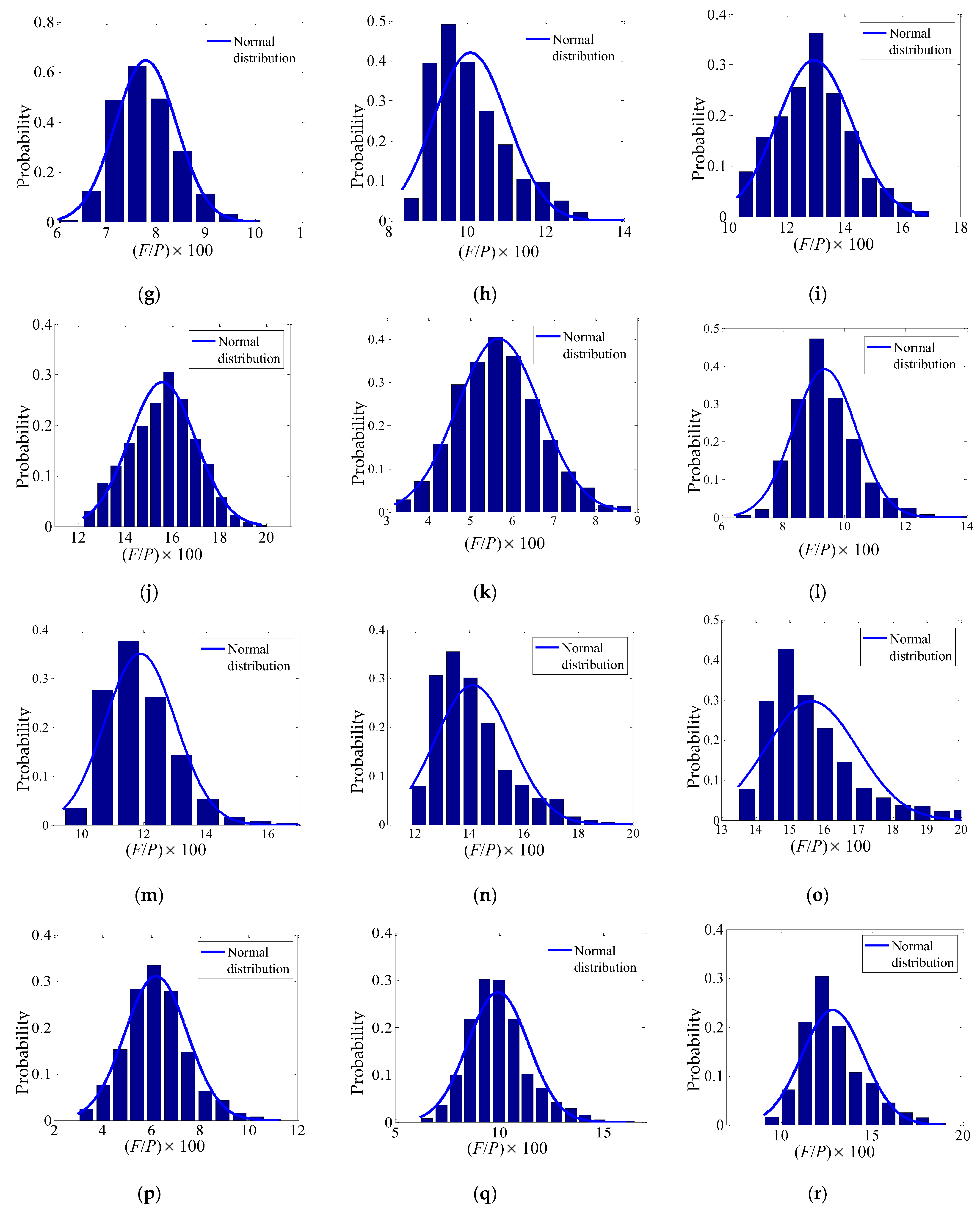
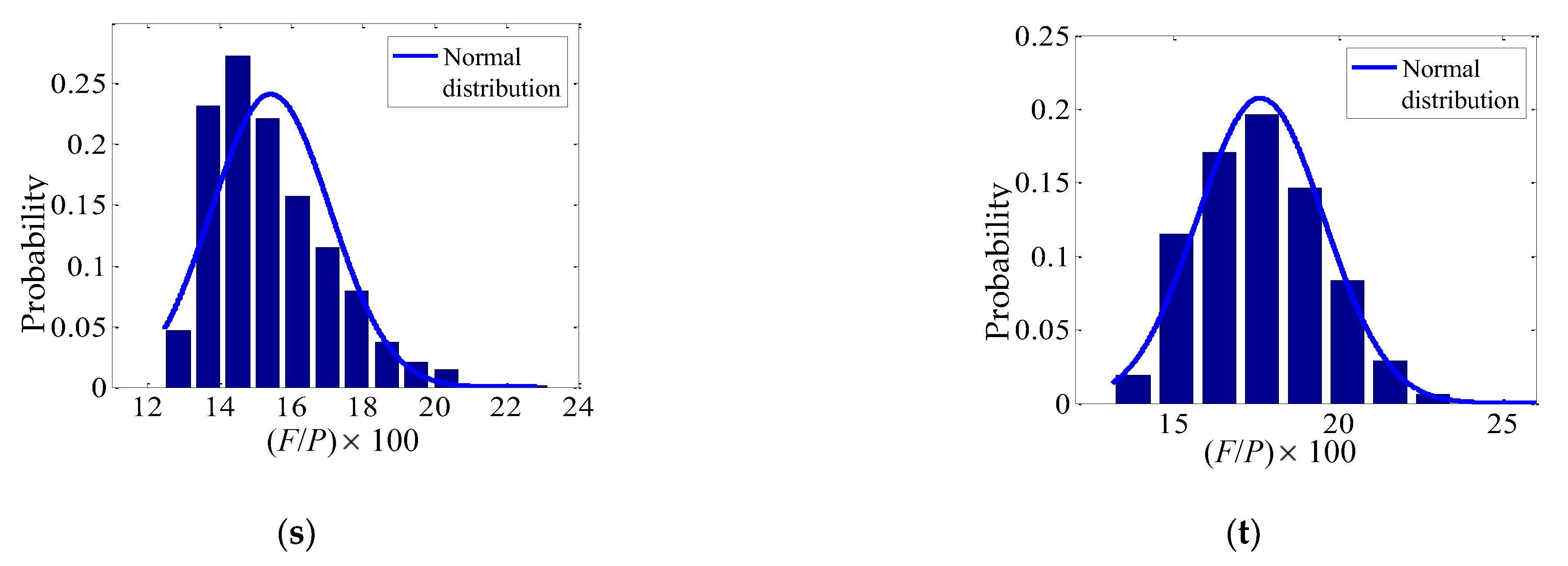
5.1. Probability Density Figures of F/P under Different Horizontal Load Combinations
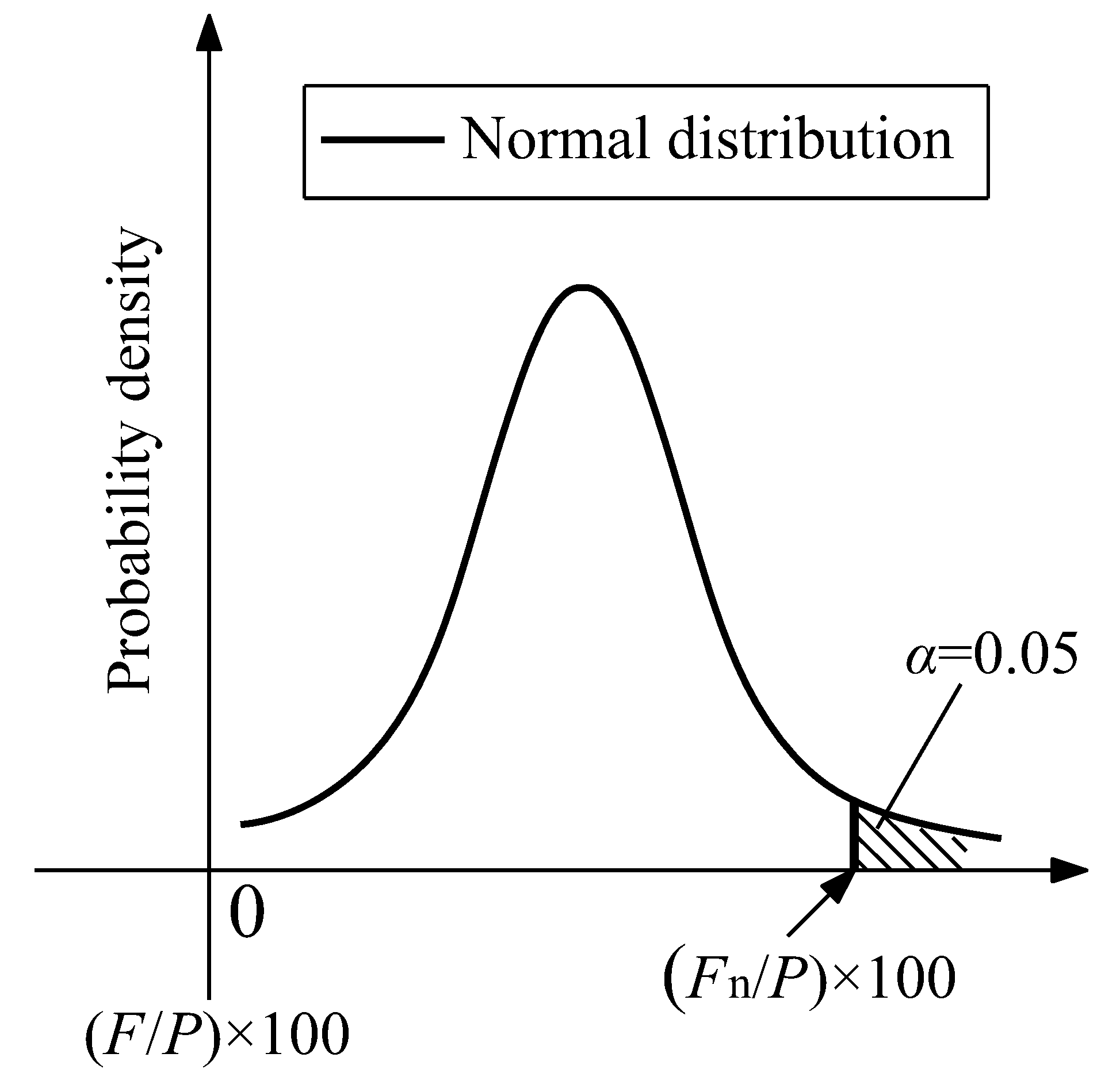
5.2. Normal Distribution of F/P
5.3. Design Intermediate-height Horizontal Braces Forces
5.4. The Most Unfavorable Horizontal Load Combination
6. Intermediate-height Horizontal Brace Forces under the Most Unfavorable Horizontal Load Combination
6.1. Probability Density Figures of F/P under the Most Unfavorable Horizontal Load Combination
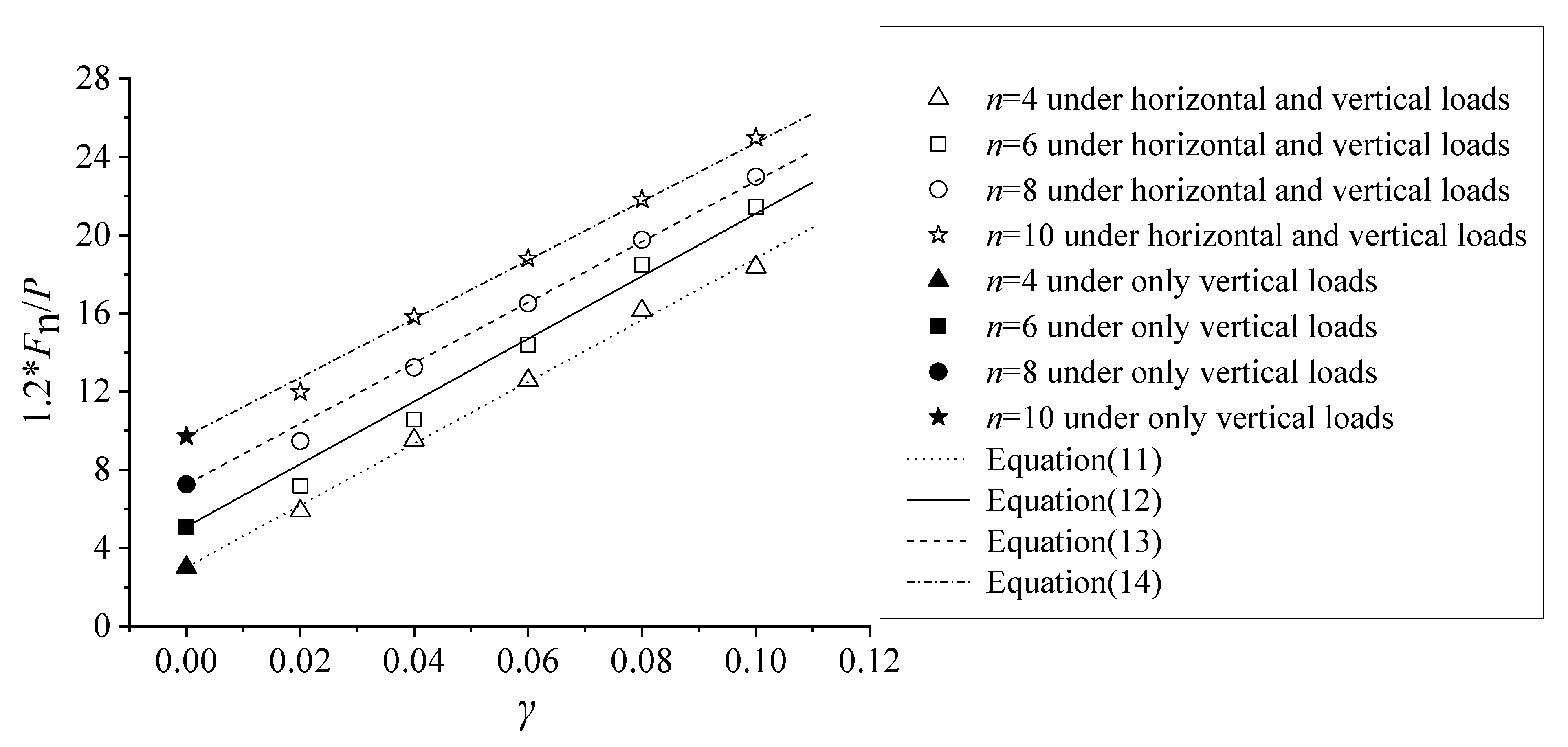
6.2. Equations of Design Intermediate-height Horizontal Brace Forces
7. Comparison with the Condition under Only Vertical Loads
8. Conclusions
- (1)
- The normal probability density equation for intermediate-height horizontal brace forces under horizontal and vertical loads was proposed, and practical equations for design intermediate-height horizontal brace forces under horizontal and vertical loads were also developed, and it was determined that the design brace forces under vertical and horizontal loads are significantly greater than those under vertical loads alone.
- (2)
- The intermediate-height horizontal brace forces under horizontal and vertical loads are also much larger than the simple superposition results for the horizontal load coefficient γ and the intermediate-height horizontal brace forces under only vertical loads, because the horizontal loads amplify the P − Δ second-order effect and decrease the effective stiffness of intermediate-height horizontal braces.
- (3)
- The whole slenderness ratio of the column about the weak axis 2λc = 200 is conservatively adopted. This is mainly because the intermediate-height horizontal brace force increases with an increase in λc. As a result of 2λc is used in most cases of practical design, the intermediate-height horizontal brace forces in engineering practice are much less than those proposed in this study.
Author Contributions
Funding
Data Availability Statement
Conflicts of Interest
References
- Winter, G. Lateral bracing of columns and beams. J. Struct. Div. ASCE 1958, 84, 1–22. [Google Scholar] [CrossRef]
- Yura, J.A. Winter’s bracing approach revised. Eng. Struct. 1996, 18, 821–825. [Google Scholar] [CrossRef]
- Tong, G.S.; Chen, S.P. Design requirement for bracing between columns. Ind. Constr. 2003, 33, 9–12. (In Chinese) [Google Scholar]
- Li, D. Stability Analysis and Bracing Requirements of Longitudinal Braced Frames; Zhejiang University: Hangzhou, China, 2005. [Google Scholar]
- Zhang, Y.C.; Zhao, J.Y.; Zhang, W.Y. Parametric Studies on Inter-column Brace Forces. Adv. Struct. Eng. 2008, 11, 305–315. [Google Scholar] [CrossRef]
- Zhao, J.Y.; Zhang, Y.C.; Lin, Y.Y. Study on mid-height horizontal bracing forces considering random initial geometric imperfections. J. Constr. Steel Res. 2014, 92, 55–66. [Google Scholar] [CrossRef]
- Chen, B.; Roy, K.; Uzzaman, A.; Raftery, G.M.; Nash, D.; Clifton, G.C.; Pouladi, P.; Lim, J.B.P. Effects of edge-stiffened web openings on the behaviour of cold-formed steel channel sections under compression. Thin-Walled Struct. 2019, 144, 106307. [Google Scholar] [CrossRef]
- Klasson, A.; Crocetti, R.; Hansson, E.F. Slender steel columns: How they are affected by imperfections and bracing stiffness. Structures 2016, 8, 35–43. [Google Scholar] [CrossRef]
- Kala, Z. Geometrically non-linear finite element reliability analysis of steel plane frames with initial imperfections. J. Civil Eng. Manag. 2012, 18, 81–90. [Google Scholar] [CrossRef]
- Sheidaii, M.R.; Gordini, M. Effect of Random Distribution of Member Length Imperfection on Collapse Behavior and Reliability of Flat Double-Layer Grid Space Structures. Adv. Struct. Eng. 2015, 18, 1475–1485. [Google Scholar] [CrossRef]
- Chen, B.; Roy, K.; Fang, Z.; Uzzaman, A.; Raftery, G.M.; Lim, J.B.P. Moment capacity of back-to-back cold-formed steel channels with edge -stiffened hole, un-stiffened hole, and plain web. Eng. Struct. 2021, 235, 112042. [Google Scholar] [CrossRef]
- Zhang, X.L.; Xue, J.Y.; Han, Y.; Chen, S.L. Model test study on horizontal bearing behavior of pile under existing vertical load. Soil Dyn. Earthq. Eng. 2021, 147, 106820. [Google Scholar]
- Dou, C.; Pi, Y.L. Effects of Geometric Imperfections on Flexural Buckling Resistance of Laterally Braced Columns. J. Struct. Eng. 2016, 142, 04016048. [Google Scholar] [CrossRef]
- Czepiżak, D.; Biegus, A. Refined calculation of lateral bracing systems due to global geometrical imperfections. J. Constr. Steel Res. 2016, 119, 30–38. [Google Scholar] [CrossRef]
- Klasson, A.; Crocetti, R.; Björnsson, I.; Hansson, E.F. Design for lateral stability of slender timber beams considering slip in the lateral bracing system. Structures 2018, 16, 157–163. [Google Scholar] [CrossRef]
- ANSYS Inc., ANSYS Mechanical APDL Structural Analysis Guide: ANSYS Release 13.0, USA, 2010. Available online: https://www.mm.bme.hu/~gyebro/files/fea/ansys/ansys_13_element_reference.pdf (accessed on 3 January 2023).
- Zhao, J.Y. Bracing Design Method of Longitudinal Column-Bracing System Under Vertical Loading; Harbin Institute of Technology: Harbin, China, 2009. (In Chinese) [Google Scholar]
- Xu, Z.J. Monte Carlo Method; Shanghai Technology and Science Publishing House: Shanghai, China, 1985. [Google Scholar]
- Nowak, A.S.; Collins, K.R. Reliability of Structures; The McGraw-Hill Education (Asia) Companies Press: Boston, MA, USA, 2000. [Google Scholar]
- Zhang, Y.C.; Jin, L.; Shao, Y.S. Practical advanced design considering random distribution of initial geometric imperfections. Adv. Struct. Eng. 2011, 14, 379–389. [Google Scholar] [CrossRef]
- Tong, G.S.; Chen, S.F. Design forces of horizontal inter-column braces. J. Constr. Steel Res. 1987, 75, 363–370. [Google Scholar] [CrossRef]
- Zhao, J.Y.; Wei, J.M.; Wang, J. Design forces of horizontal braces unlocated at middle of columns considering random initial geometric imperfections. Adv. Civil Eng. 2021, 2021, 1264270. [Google Scholar] [CrossRef]
- Wei, J.P.; Tian, L.M.; Hao, J.P.; Li, W.; Zhang, C.B.; Li, L.J. Novel principle for improving performance of steel frame structures in column-loss scenario. J. Constr. Steel Res. 2019, 163, 105768. [Google Scholar] [CrossRef]
- Chen, B.; Roy, K.; Uzzaman, A.; Raftery, G.M.; Lim, J.B.P. Moment capacity of cold-formed channel beams with edge-stiffened web holes, un-stiffened web holes and plain webs. Thin-Walled Struct. 2020, 157, 107070. [Google Scholar] [CrossRef]
- Piątkowski, M. Experimental research on load of transversal roof bracing due to geometrical imperfections of truss. Eng. Struct. 2021, 242, 112558. [Google Scholar] [CrossRef]
- Wang, L.; Helwig, T.A. Critical Imperfections for Beam Bracing Systems. J. Struct. Eng. 2005, 131, 933–940. [Google Scholar] [CrossRef]
- GB50205; Code for acceptance of construction quality of steel structures. Chinese Planning Press: Beijing, China, 2001.
- O’Reilly, G.J.; Goggins, J. Experimental testing of a self-centring concentrically braced steel frame. Eng. Struct. 2021, 238, 111521. [Google Scholar] [CrossRef]
- Meng, B.; Zhong, W.H.; Hao, J.P.; Song, X.Y. Improving anti-collapse performance of steel frame with RBS connection. J. Constr. Steel Res. 2020, 170, 106119. [Google Scholar] [CrossRef]
- Shen, P.W.; Yang, P.; Hong, J.H.; Yang, Y.M.; Tuo, X.Y. Seismic performance of steel frame with a self-centering beam. J. Constr. Steel Res. 2020, 175, 106349. [Google Scholar] [CrossRef]


| Test | Test Results | FE Analysis Results | Puf/Put | Fuf/Fut | ||||
|---|---|---|---|---|---|---|---|---|
| Ultimate Loads Put /N | Maximum Horizontal Brace Force Fut/N | Fut/Put | Ultimate Loads Put /N | Maximum Horizontal Brace Force Fut/N | Fut/Put | |||
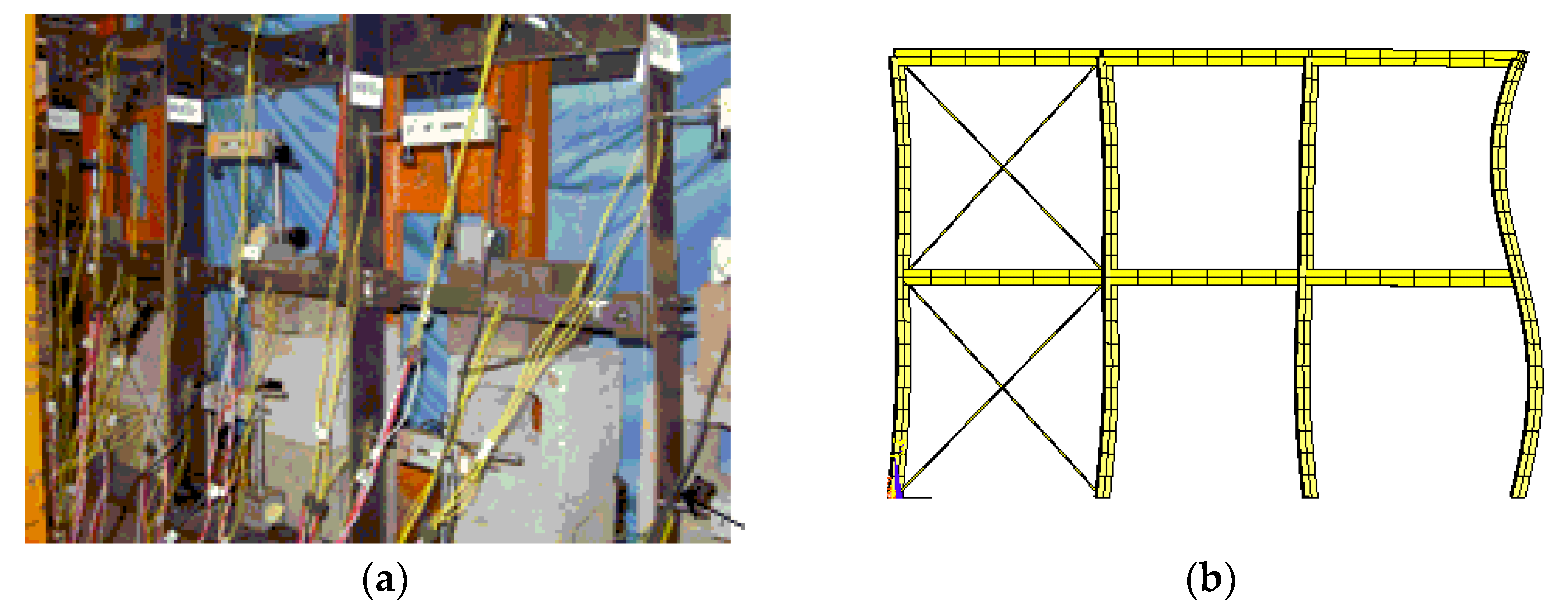
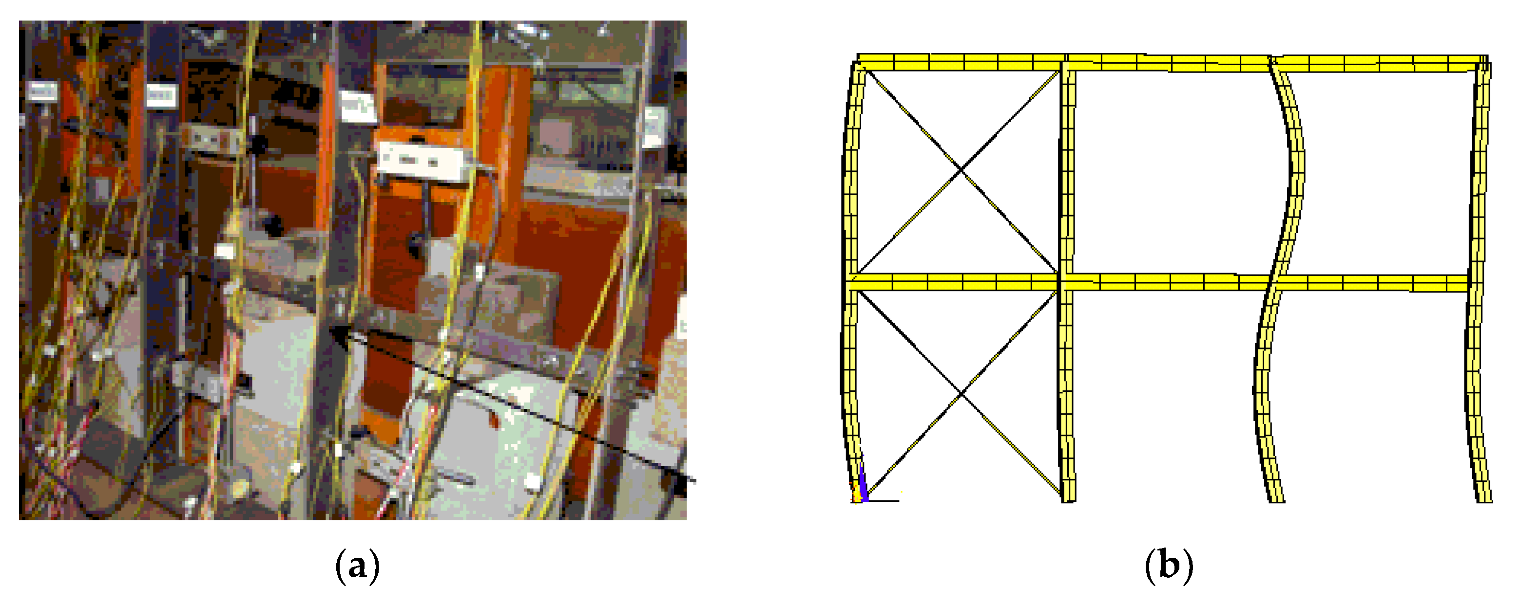
| Group 1 | 7616 | 492 | 0.065 | 8145 | 617 | 0.076 | 1.07 | 1.25 |
| Group 2 | 7121 | −484 | −0.068 | 7830 | −609 | −0.078 | 1.11 | 1.26 |
| b/L | L (m) | H (mm) | tw (mm) | B (mm) | tf (mm) | Ad (cm2) |
|---|---|---|---|---|---|---|
| 0.4 | 15 | 800 | 15 | 352.54 | 19.26 | 14.0 |
| 0.5 | 12 | 800 | 17 | 298.81 | 20.22 | 12.0 |
| 0.6 | 10 | 800 | 18 | 256.49 | 22.22 | 11.2 |
| 0.7 | 8.57 | 800 | 19 | 226.98 | 23.56 | 10.5 |
| λb | Ai /At (cm2) | Db (mm) | tb (mm) |
|---|---|---|---|
| 100 | 24 | 169.65 | 4.50 |
| 125 | 32 | 135.56 | 7.51 |
| 150 | 42 | 112.51 | 11.88 |
| 175 | 53 | 95.35 | 17.69 |
| 200 | 64 | 81.01 | 25.14 |
| n | Direction of the Horizontal Loads | Different Horizontal Load Combinations (γ = 0.02) | Statistical Character | Fn/P | 1.2 × Fn/P |
|---|---|---|---|---|---|
| 8 | To the left | γ1 = 0, γ2 = γ | μ = 5.6789; σ = 0.9944 | 7.31% | 8.77% |
| γ1 = γ/2, γ2 = γ/2 | μ = 5.4559; σ = 0.9468 | 7.01% | 8.41% | ||
| γ1 = γ, γ2 = 0 | μ = 5.2668; σ = 0.9556 | 6.78% | 8.14% | ||
| To the right | γ1 = 0, γ2 = γ | μ = 4.7061; σ = 0.8022 | 6.01% | 7.21% | |
| γ1 = γ/2, γ2 = γ/2 | μ = 4.6539; σ = 0.8139 | 5.98% | 7.18% | ||
| γ1 = γ, γ2 = 0 | μ = 4.6083; σ = 0.8308 | 5.96% | 7.15% |
| n | Horizontal Load Coefficient γ | Statistical Character | Fn/P | 1.2 × Fn/P |
|---|---|---|---|---|
| 4 | 0.02 | μ = 4.0113; σ = 0.3830 | 4.92% | 5.90% |
| 0.04 | μ = 6.6207; σ = 0.6571 | 7.94% | 9.53% | |
| 0.06 | μ = 8.4798; σ = 0.9039 | 10.48% | 12.58% | |
| 0.08 | μ = 10.8835; σ = 0.9929 | 13.45% | 16.14% | |
| 0.1 | μ = 13.4693; σ = 1.1447 | 15.31% | 18.37% | |
| 6 | 0.02 | μ = 4.8525; σ = 0.692 | 5.99% | 7.19% |
| 0.04 | μ = 7.7989; σ = 0.6184 | 8.82% | 10.58% | |
| 0.06 | μ = 10.0892; σ = 0.9500 | 11.99% | 14.39% | |
| 0.08 | μ = 12.3699; σ = 1.4123 | 15.40% | 18.48% | |
| 0.1 | μ = 15.5835; σ = 1.4011 | 17.88% | 21.46% | |
| 8 | 0.02 | μ = 6.0589; σ = 0.9944 | 7.89% | 9.47% |
| 0.04 | μ = 9.3664; σ = 1.0182 | 11.04% | 13.24% | |
| 0.06 | μ = 11.888; σ = 1.1361 | 13.76% | 16.51% | |
| 0.08 | μ = 14.141; σ = 1.3949 | 16.47% | 19.76% | |
| 0.1 | μ = 16.3568; σ = 1.6762 | 19.16% | 22.99% | |
| 10 | 0.02 | μ = 7.7995; σ = 1.2853 | 9.98% | 11.98% |
| 0.04 | μ = 9.9542; σ = 1.4562 | 12.35% | 14.82% | |
| 0.06 | μ = 12.8625; σ = 1.6991 | 15.67% | 18.80% | |
| 0.08 | μ = 15.4395; σ = 1.6526 | 18.18% | 21.82% | |
| 0.1 | μ = 17.6446; σ = 1.9234 | 20.82% | 24.98% |
| n | γ | 1.2 × Fn/P | γ + 1.2 × Fn/P (γ = 0) |
|---|---|---|---|
| 4 | 0 | 3.02% | — |
| 0.02 | 5.90% | 5.02% | |
| 0.04 | 9.53% | 7.02% | |
| 0.06 | 12.58% | 9.02% | |
| 0.08 | 16.14% | 11.02% | |
| 0.1 | 18.37% | 13.02% | |
| 6 | 0 | 5.10% | — |
| 0.02 | 7.19% | 7.10% | |
| 0.04 | 10.58% | 9.10% | |
| 0.06 | 14.39% | 11.10% | |
| 0.08 | 18.48% | 13.10% | |
| 0.1 | 21.46% | 15.10% | |
| 8 | 0 | 7.26% | — |
| 0.02 | 9.47% | 9.26% | |
| 0.04 | 13.24% | 11.26% | |
| 0.06 | 16.51% | 13.26% | |
| 0.08 | 19.76% | 15.26% | |
| 0.1 | 22.99% | 17.26% | |
| 10 | 0 | 9.72% | — |
| 0.02 | 11.98% | 11.72% | |
| 0.04 | 14.82% | 13.72% | |
| 0.06 | 18.80% | 15.72% | |
| 0.08 | 21.82% | 17.72% | |
| 0.1 | 24.98% | 19.72% |
Disclaimer/Publisher’s Note: The statements, opinions and data contained in all publications are solely those of the individual author(s) and contributor(s) and not of MDPI and/or the editor(s). MDPI and/or the editor(s) disclaim responsibility for any injury to people or property resulting from any ideas, methods, instructions or products referred to in the content. |
© 2023 by the authors. Licensee MDPI, Basel, Switzerland. This article is an open access article distributed under the terms and conditions of the Creative Commons Attribution (CC BY) license (https://creativecommons.org/licenses/by/4.0/).
Share and Cite
Yang, H.; Liu, S.; Fang, Z.; Zhao, J. Investigation of Intermediate-Height Horizontal Brace Forces under Horizontal and Vertical Loads including Random Initial Imperfections. Buildings 2023, 13, 180. https://doi.org/10.3390/buildings13010180
Yang H, Liu S, Fang Z, Zhao J. Investigation of Intermediate-Height Horizontal Brace Forces under Horizontal and Vertical Loads including Random Initial Imperfections. Buildings. 2023; 13(1):180. https://doi.org/10.3390/buildings13010180
Chicago/Turabian StyleYang, Haixu, Shuo Liu, Zhiyuan Fang, and Jinyou Zhao. 2023. "Investigation of Intermediate-Height Horizontal Brace Forces under Horizontal and Vertical Loads including Random Initial Imperfections" Buildings 13, no. 1: 180. https://doi.org/10.3390/buildings13010180