Article

Timber Buildings Deconstruction as a Design Solution toward Near Zero CO2e Emissions

Department of Civil Engineering—Via Giovanni Paolo II, University of Salerno, 132-84084 Fisciano, SA, Italy
*
Author to whom correspondence should be addressed.
Buildings 2023, 13(1), 157; https://doi.org/10.3390/buildings13010157
Submission received: 20 November 2022 / Revised: 31 December 2022 / Accepted: 6 January 2023 / Published: 7 January 2023
(This article belongs to the Collection Low-Carbon Buildings and Urban Energy Systems)

Abstract

:
The overall reduction in the environmental impacts of the construction industry is a complex process that requires methodological and applicative studies on the evaluation of the sustainability of the life cycle, related to both individual product and of the building system as a whole. In this context, with reference to the end-of-life phase of the building, the management of the disassembly and selective demolition plan of the building, allowing the reuse or recycling of the materials as well as of the building components and prefabricated elements used is fundamental. This research aimed to develop a methodology, applied to timber building systems, to mitigate CO2e emissions during the decommissioning and disposal of the building. The quantitative model developed considers the rates of the CO2e emissions involved in C (end-of-life) and D (benefits and loads beyond the system boundary) phases of building sustainability assessment. The model was applied to two wooden buildings: one with an XLAM structure and another one with a framed structure. In both cases, from the perspective of reusing the wood components for a subsequent life cycle, C and D phases of the process achieved an overall negative CO2e emission rate thanks to the offsetting from the carbon storage property of wood. This research has thus demonstrated the possibility of making the wood construction process circular through a zero-emission approach.

1. Introduction

The European Green Deal [1] is an integral part of the European Commission’s strategy to implement the goals of the 2030 Agenda [1] (i.e., reducing greenhouse gas emissions by 55% compared to the 1990 values and achieving climate neutrality by 2050). To analyze the energy and environmental impacts of the building sector throughout its life cycle, it is necessary to refer to indicators of the sustainability of materials, construction systems, and buildings such as embodied energy (EE) and operational energy (OE) [2]. The embodied energy is the energy required for the extraction and processing of raw materials, the transport and assembly of finished products on site, and for maintenance, renovation, demolition, and waste disposal at the end-of-life. Operational energy, on the other hand, is the amount of energy required to operate the building during its lifetime. The embodied and operational energy rates correspond to consequent CO2e emission factors: embodied carbon (EC) and operational carbon (OC). Therefore, designing an energy-efficient building in the operational phase is a necessary but not sufficient condition, considering the additional emission rates resulting from the use of resources in other phases of the life cycle. The construction sector accounts for 37% of global CO2 emissions into the atmosphere; it accounts for 34% of all global energy consumption, 50% of raw material extraction, and consumes one third of drinking water [3]. It uses a considerable amount of raw materials and energy during the life cycle phases of the constructing process: production, construction, use, maintenance until demolition (i.e., a linear process ‘from Cradle to Grave’) (Figure 1).
The desirable process to reduce resource consumption and mitigate environmental impact should be circular. The closing of the circle is realized with the re-introduction into the system through the recycling operations of products that would otherwise reach the end of their life, reducing waste as much as possible, in accordance with the ‘C2C—from Cradle to Cradle’ principle (Figure 2).

2. State-of-the-Art

The life cycle assessment (LCA) method is one of the most widely used tools for identifying the most suitable materials in sustainable construction. It compares the environmental impact of different building materials and directs the design toward the use of materials with low energy consumption. This method considers the whole life cycle, from the production of materials to their end-of-life (Figure 3).
Initial studies on the embodied energy of buildings [4] found that over a 50-year lifespan, embodied energy accounted for 45 percent of the total energy needs. For this reason, the life cycle analysis mainly focused on reducing the OE and neglected the energy consumption of the other life cycle phases. This reduction has been made possible in the last two decades by stricter energy regulations and standards in accordance with the evolution of various European legislations (CEN).
The European standard EN 15978:2011 [5] specifies the calculation method, based on life cycle assessment (LCA) and other quantified environmental information, to evaluate the environmental performance of a building. It also defines the system boundary that is applied to the building level: the production phase (including extraction of raw materials, A1; transport of raw materials, A2; production of building materials, A3; their transport, A4; and their installation, A5); the use phase (including use, B1; maintenance, B2; repair, B3; replacement, B4; renovation, B5); the end-of-life phase of the building (including deconstruction, C1; transport of materials, C2; waste treatment, C3; and the final disposal phase, C4); and the beyond-life phase of the building, module D (scenarios for reuse, recycling, and energy recovery from obsolete materials and associated environmental impacts).
Wu et al. (2012) [6] highlighted, by means of an LCA approach, the prevalent consumption of operational energy in an office building in China. They also pointed out that the treatment of building materials at the end of their life is an important aspect affecting the environmental performance of the building. Some environmental improvements aimed at reducing energy consumption and CO2 emissions throughout the building’s life cycle are also provided.
Bontempi (2021) [7] highlighted that the development of reliable and often open-access databases containing EC (embodied carbon) and EE (embodied energy) associated with many raw materials has contributed to the development of sustainability analysis tools based on energy use and emissions. Thanks to the use of general parameters (EC and EE), in principle, these approaches can be applied to all sectors and can be considered as pre-screening methods, preliminary to a complete LCA.
A further evolution of the LCA methodology can be found in studies that investigate A to C modules (i.e., including end-of-life considerations, ‘C2G—from Cradle to Grave’). In this sense, evaluating both the embodied and operational emissions of different office building retrofit scenarios (in Norway), Rabani et al. (2021) [8] extended the scope of the investigation to module C.
Di Ruocco et al. (2021) [9] investigated the criteria and approaches adopted in a series of case studies to develop a useful tool to identify the ‘sustainable trade-off’ of opaque envelopes. This study proposes, through the comparison of the application of two methods (TOPSIS and COMPROMISE), the analysis of the materials used in the design by considering a series of performance and environmental characteristics in relation to the content of recycled materials, the end-of-life destination of these materials: embodied energy and embodied carbon.
Therefore, to protect non-renewable resources and reduce land consumption, Di Ruocco et al. [10] developed a methodology aimed at the sustainability of rehabilitation and conservation interventions of protected buildings through a life cycle building (LCB) approach, minimizing CO2e emissions. The model was developed based on modules A, C, and D (A1–A3: production, C1–C4: end-of-life, and D: benefits beyond the system boundaries). The results show that the most relevant contributions, in terms of CO2e reduction, come from the use of dry-assembled wood technology units.
Gomes et al. (2020) [11] evaluated the environmental, economic, and energy performance of different flat roof solutions, C2C, to support the selection of the best alternative to be used in each building. The results showed that inverted flat roof solutions have, in general, a worse environmental performance than traditional solutions.
In light of the state-of-the-art analysis, the following considerations have emerged:
  • The circular C2C (form cradle to cradle) approach has only been partially investigated;
  • Among the case studies analyzed, very few refer to timber construction systems;
  • No study has evaluated, within the C2C approach, the potential of wood systems for carbon storage.
Therefore, with reference to the criticalities and gaps found in the state-of-the-art, this study means to elaborate a methodology applicable to timber construction systems that allows one to evaluate the reduction in embodied energy and carbon in the transition phases between the cradle to grave.
Specifically, this study aimed to investigate the potential of wood building systems, in terms of reducing CO2e emissions related to the selective deconstruction process, at the end-of-life, by evaluating the different performance of two wood building systems:
  • Frame structure;
  • XLAM panel structure.

3. Tools and Methods

The tools used for the purpose of methodological development are:
To estimate the CO2e,1 component, the emissions from the machinery and equipment required for selective deconstruction operations were considered;
To estimate the CO2e,2 component, the integration of virgin raw material of the amount of scrap as loss of damaged material, as a result of deconstruction operations, was considered. Emissions result from the production of the amount of material to be integrated and the EC factor from an open-access database, Inventory Carbon and Energy (ICE) [12], corresponding to the A1–A3 phases (cradle to gate);
To estimate the CO2e,3 component, the emissions derived from transporting the deconstructed materials from the demolition site to the processing/storage company were calculated;
To estimate the CO2e,4 component, the emissions of the machinery and equipment required for restoring the wooden components, in order to put them back into the market, were calculated;
To estimate the CO2e,5 component, the negative factor indicated by ICE [12] for the cradle-to-gate phase was considered, multiplied by the amount of material recovered by selective deconstruction (therefore net of the amount of XLAM of scrap). Therefore, this value expresses the potential of the circular approach of the methodology: it corresponds to the gain, in terms of emissions, connected to the reuse of the components in the next life cycle, thus avoiding (for this quantity) the impact related to the extraction of virgin raw material and its transformation (corresponding to the A1–A3 phases).
The methodology also takes into account an Italian sustainability protocol, CAM—Minimum Environmental Criteria [13], which defines the environmental requirements useful for identifying the best design solution, product, or service with regard to the life cycle of the work.
The methodology developed was divided into the following phases:
  • Phase I: Definition of the scope of investigation;
  • Phase II: Technological characterization of the building;
  • Phase III: Estimation of CO2e emissions;
  • Phase IV: Assessment of the level of disassembly;
  • Phase V: Estimation of waste streams and quantities and the verification of the Italian CAM parameters [13].

3.1. Phase I: Definition of the Scope of Investigation

According to the European Standard EN 15978:2001 [5], the aim of the proposed methodology is to estimate the environmental impact, in terms of CO2e emissions, of the end-of-life phase of wood building systems. Specifically, the scope of the investigation was constituted by modules C and D that concern, respectively, the end-of-life phase and the benefits/charges derived from reuse, recovery, and potential recycling activities (Table 1).

3.2. Phase II: Technological Characterization of the Building

The technological characterization of the building was based on the UNI 8290-1:1981 standard [18], thanks to which it is possible to break down the building into classes of technological units (1st level), each class of technological unit is in turn broken down into technological units (2nd level), and each technological unit is in turn broken down into technical elements (3rd level). Air conditioning, plumbing, fire protection, and burglar alarm systems as well as and exterior furniture are not included in the classification as they are considered invariant. In addition, the type of connections of the different materials that make-up the technical elements were evaluated; to do this, the UNI 11277:2008 standard [19] was taken into consideration by associating each construction system with an installation technology. The identification of the type of construction system, the prevailing materials that make-up the technical elements, and the type of connection has a fundamental importance to subsequently define the work necessary for disassembly and selective demolition.

3.3. Phase III: Estimation of CO2e Emissions

In the third step, the CO2e emissions generated by a selective disassembly and demolition process during the whole end-of-life phase of a building with a timber construction system were estimated.
The CO2e emissions were obtained from the sum of five rates:
  • Positive rate of CO2e,1 from the demolition activities;
  • Positive rate of CO2e,2 from scrap resulting from demolition activities;
  • Positive rate of CO2e,3 from off-site transport;
  • Positive rate of CO2e,4 from transformation/treatment activity for further reuse;
  • Negative rate of CO2e,5 as emissions credit for storage in the material.
CO2e = CO2e,1 + CO2e,2 + CO2e,3 + CO2e,4 − CO2e,5

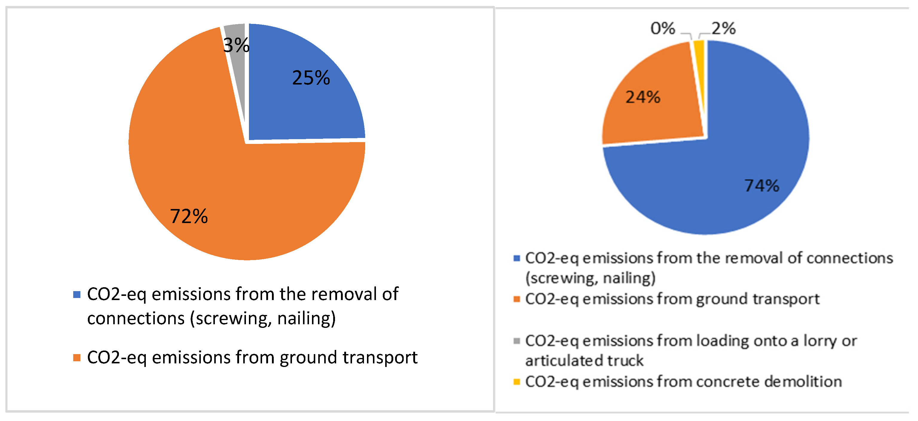
3.3.1. Positive Rate of CO2e,1 from Demolition Activity

To identify the type of work necessary for the disassembly and selective demolition of each technical element, the demolition activity was divided into three operations: removal of the connections, transport to the ground, and loading onto a truck or articulated truck of the technical elements. In this way, depending on the construction system and the installation technology, the tool and/or machinery used for the removal of the connections (Table 1), and the transport mode to the ground and loading onto a truck or articulated truck were defined, according to the dimensional characteristics of the material.
Then, the weight and length ranges were defined according to the maximum weight that can be lifted by an operator under optimal conditions, which the standard sets at 25 kg [20], and the maximum load and size that can be transported by the lifting equipment (telescopic handlers, telescopic cranes) were deduced by consulting the technical data sheets [21,22,23,24] (Table 2).
No distinction has been made as to where the elements are loaded onto a truck or articulated truck before dismantling as they are transported on the ground to a temporary storage site on the construction site; at a later phase, they will be loaded in homogeneous groups onto the transport equipment (Table 3).
In addition, for the removal of connections located at a height above the work surface, the use of lifting equipment is envisaged (Table 4) [25,26]. In a second step, to estimate the CO2e emissions generated by using the tools necessary for the connection removal, the operating times were determined for each of them by watching videos provided by the manufacturers of the devices, videos corresponding to real cases, data sheets, and data collected in the literature (Table 5). Various machines were used to transport the elements to the ground and load them onto a truck and/or articulated truck. Their operating times were estimated by consulting the data sheets and videos corresponding to real cases [21,24,27,28,29,30,31].
Time (in seconds) needed to carry out the operations were divided into five classes:
  • T0 = time needed to reach the n-th floor (ascent);
  • T0′ = time needed to reach the ground floor (descent);
  • T1 = time needed to connect the element to the crane hook in the case of XLAM panels and framed panels, seconds needed to load the lift basket in the case of groups of items with L < 3.20 m and P < 2000 kg;
  • T2 = time needed to reach the storage site within the construction site (50 m);
  • T3 = time needed to load the elements onto a truck and/or articulated truck.
At this point, knowing the operating times of tools and machinery, it is possible to estimate the rate of the CO2e emissions generated by the demolition activity as the sum of two further rates:
-
The one generated by using tools for the connections removal, obtained as the product of the operating time (in seconds) of the tools or the maximum chipping capacity, the number of connections to be removed or the volume to be chipped, and the consumption of the tools by the emission factor (Table 6);
-
The one generated by using machinery for the transport to the ground and the loading on a truck and/or articulated truck of an item or groups of items, obtained as the product of the seconds of the operation of the machinery, the number of trips, the consumption of the machinery, and the emission factor (Table 7).

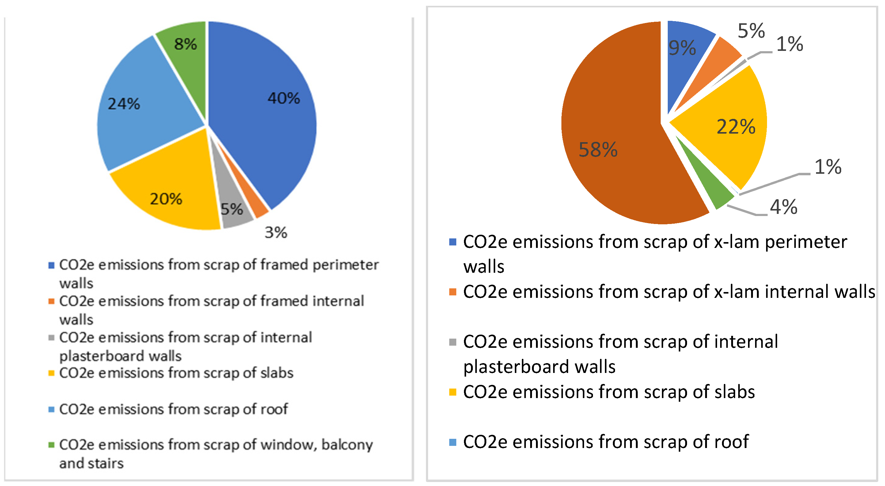
3.3.2. Positive Rate of CO2e,2 from Scrap Resulting from Demolition Operations

Demolition activities can generate scrap (i.e., a proportion of materials that cannot be recovered after removal because it has been damaged). The proportion of CO2e emissions from demolition waste corresponds to the embodied carbon in the proportion of non-recoverable materials. The percentage of scrap is the difference between 100% of the material and the percentage of reusable materials. The reusability index (IR) was used to determine the reusability rate, which was evaluated in relation to the construction system and the installation technology (Table 8).
At this point, knowing the percentage of materials that cannot be recovered after removal as it is damaged, it is possible to estimate the rate of CO2e emissions produced by the scrap resulting from demolition operations.
CO2e,2 = material weight × (% scrap) × embodied carbon of the materials
Embodied carbon values were taken from the Environmental Performance in Construction (EPiC) [32] produced by the University of Melbourne and the Inventory of Carbon and Energy (ICE) [12] produced by the University of Bath.

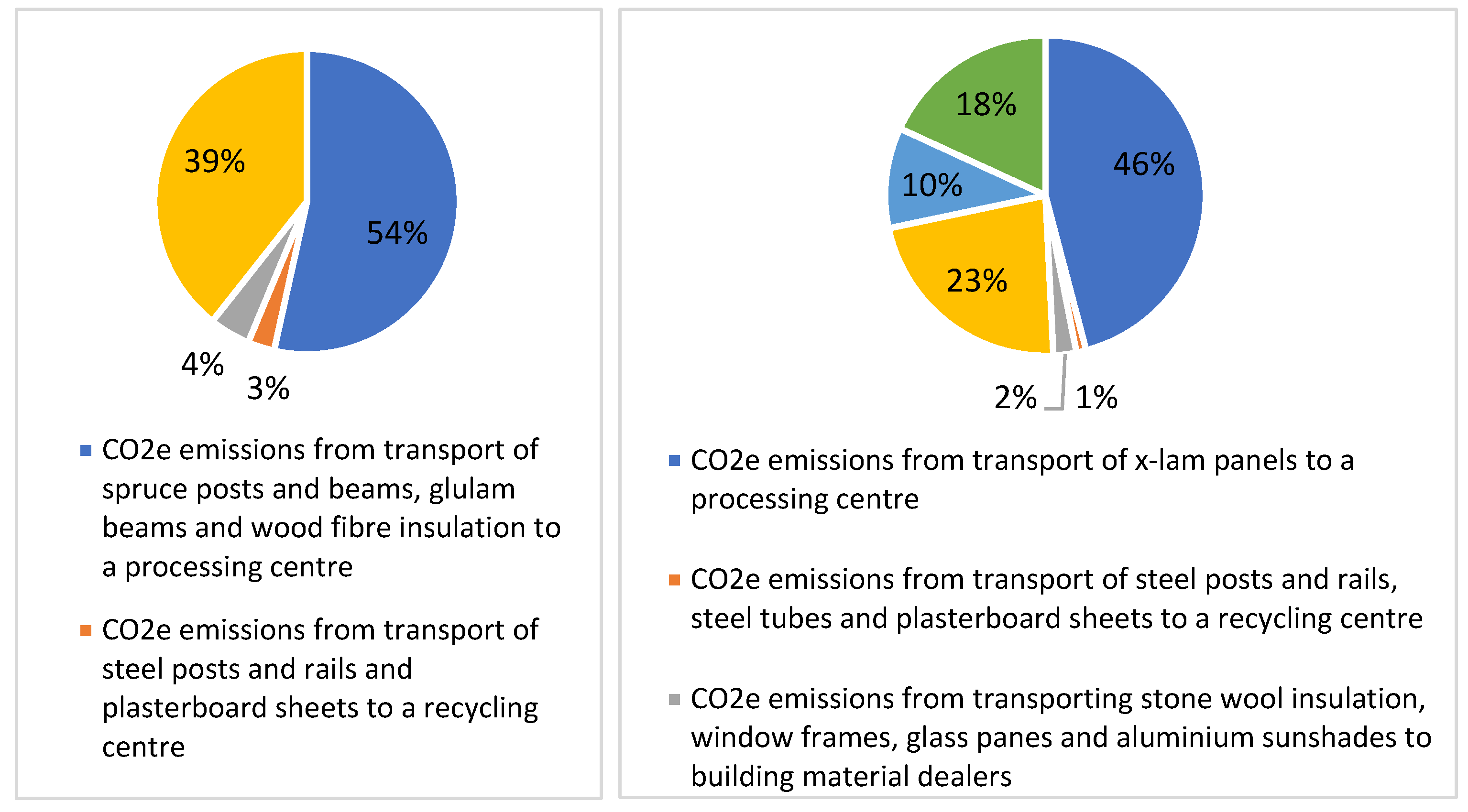
3.3.3. Positive Rate of CO2e,3 from Off-Site Transport

Following the demolition activity, materials will be transported to special storage areas within the site, and then moved to processing centers or retailers of construction materials from demolition if they are reusable; to recycling centers if they are recyclable; or to waste disposal centers if they are to be disposed of.
The first step is to classify the selective demolition materials according to EWC-Stat categories [33], which assigns a European Waste Code (EWC) to each category. To undertake this study, only wood elements will be investigated.
  • In the case of future reuse activities, wooden components need to be reconditioned in a processing center before being reintroduced into the production cycle. Therefore, after leaving the construction site, a means of transport drives them to the processing center and then the new construction site.
  • In the case of future recycling activities, wooden components are directly transported from the demolition site to a recycling center.
  • Components made of other materials are transported to building material dealers in the case of re-use; to recycling centers if they are recyclable; and to disposal centers if a second life is not possible.
  • For the disposal of hazardous waste, the only destination of the transport vehicle is the disposal center.
Once the steps that the vehicle must take to transport the three categories have been established, we need to define the number of trips from the demolition site to the future destinations. This number is strongly influenced by the chosen articulated truck model, specifically by the size of the container, the maximum transportable volume, and the maximum transportable load. Starting with the maximum transportable volume, the volume of the first tranche of elements to be transported is subtracted in order to obtain the remaining volume. The procedure is repeated until all groups of elements have been loaded. At this point, knowing the type of transport means used and defining the methodology for calculating the number of trips from the demolition site to the future destination, it is possible to estimate the rate of CO2e emissions produced by off-site transport.
CO2e,3 = distance travelled × number of travels × emission factor

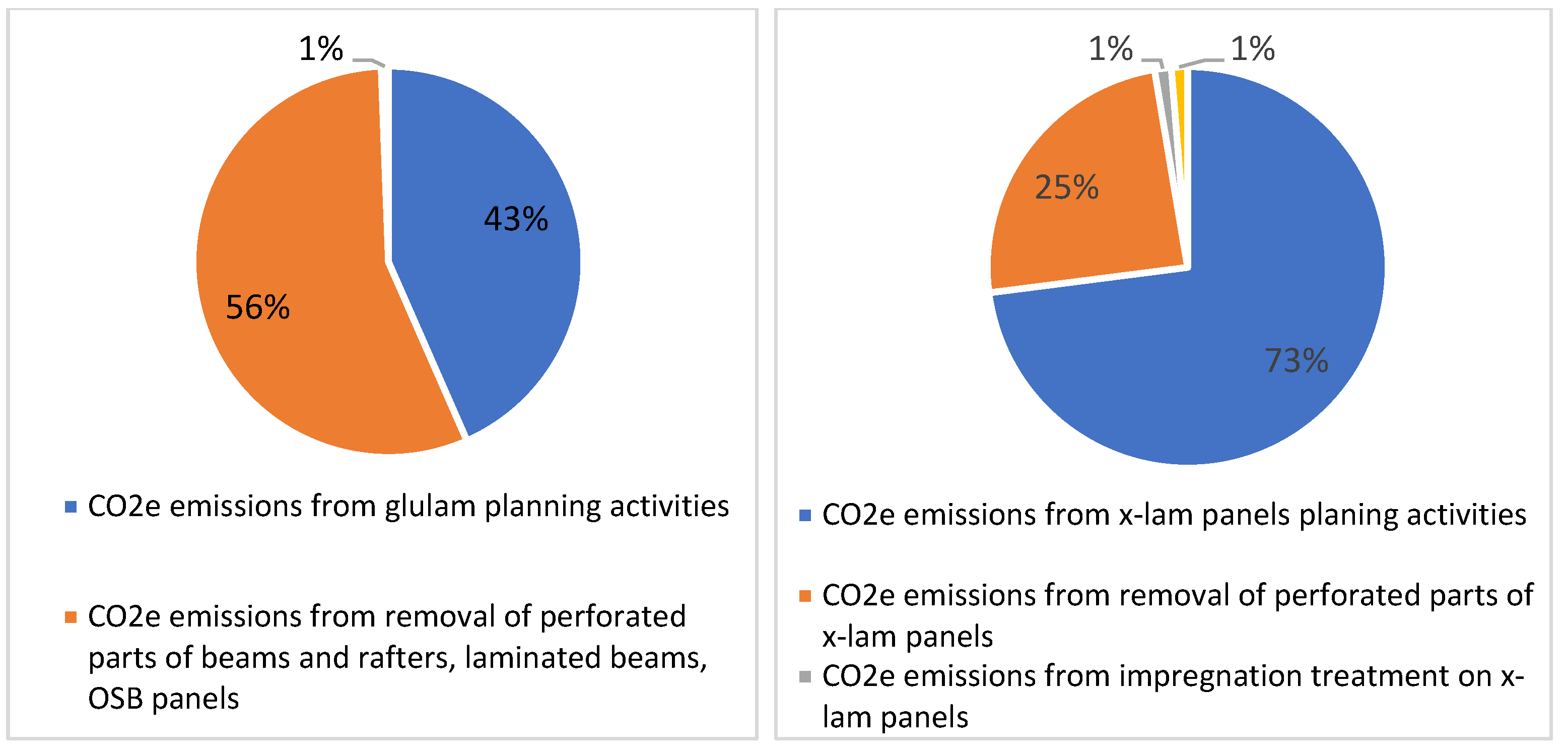
3.3.4. Positive Rate of CO2e,4 from Transformation/Treatment Activity for Further Reuse

As previously explained, following the disassembly and selective demolition process, the wooden elements of the elevation structure (XLAM panels, bearing panels, and beams) need transformation/treatment activities before being reintroduced into the market. Therefore, the first step is to determine these activities and the machinery by which they are carried out. Subsequently, the operating times are determined based on the machinery speeds, which were determined by consulting the technical data sheets [34,35,36,37] (Table 9).
At this point, after knowing the operating times of the machinery used, it is possible to estimate the rate of CO2e emissions generated by the processing/treatment activities. The latter is obtained as the product of the size of the item to be treated, the number of activities to be performed, the operating speed of the machinery, the power, and the emission factor (Table 10).

3.3.5. Negative Rate of CO2e,5 as Emissions Credit for Storage in Material

Trees, as living organisms, absorb carbon dioxide from the atmosphere, convert it into carbon, and release oxygen into the environment. For this reason, wooden buildings are a valuable carbon store. Wooden elements are able to store CO2e, which will be returned to the environment when they are incinerated (i.e., when no further life cycle is possible for them). Due to this characteristic, the CO2e,5 rate, related to the storage of the material, is a negative rate that reduces the total emissions.
CO2e,5 = weight of scrap wood elements × embodied carbon net of wooden elements
The net embodied carbon is obtained as the difference between the value of EC including carbon storage and the value of EC not including carbon storage; furthermore, the weight of the scrap is considered rather than the total weight of the wood elements in light of the fact that the scrap will be sent to incinerating operations for energy production with consequent release of the stored CO2, while the reused and recycled elements will continue to retain the share of stored CO2.

3.4. Phase IV: Assessment of the Level of Disassembly

The potential for the re-use of building bodies, building components, and building materials is closely related to their level of disassembly, which represents the ability of a building, building component, or building material to be disassembled and re-introduced into the production cycle, therefore establishing a sustainable continuity between the end-of-life phase (decommissioning of the building) and the production phase of the individual building components. The current approach to assessing the level of disassembly (LID) of a technological unit, technical element, or prevailing material is dictated by UNI 11277:2008 [19].

3.4.1. UNI Method

The method proposed by the UNI standard [19] assigns a score, from 0 to 5, exclusively according to the laying technology and the construction system of the prevailing material. Once the score of each prevailing material is known, the level of disassembly of the technological unit is considered equal to the average of the scores of the prevailing materials composing it (Table 11).
This method, being devoid of indicators or information on the phases following the disassembly phase and preceding the reintroduction of the single prevailing materials within the production cycle, allows for a partial evaluation of the level of disassembly (LID) of a building or a single technological unit. To define an integrated method for the evaluation of the level of disassembly, the research proposes an implementation of the classification made by the UNI 11277:2008 standard.

3.4.2. Integrated Experimental Method

The integrated experimental method implements the classification made by the UNI 11277:2008 standard, based on data collected in the literature [38,39]. Two other parameters are added to the construction system and laying technology parameter: damage generated by handling and transport and transformation activities. The score (LID) to be assigned to each prevailing material, belonging to a given technological unit, is obtained from the sum of the products between the recovery potential, chosen for each parameter according to the sub-parameters, and the weights assigned to each parameter (Table 12). The score to be assigned to the technical element is obtained as the average of the scores of the prevailing elements composing it.

3.5. Phase V: Estimation of Waste Streams and Quantities and Verification of CAM Parameters

The last step of the methodology is to estimate the kinds and quantities of waste generated during the whole disassembly and selective demolition process. The estimation of waste streams is conducted by assigning to each material the EWC (European Waste Code) provided by the List of Wastes [33]. The estimation of the quantities of waste for reuse, recycling, and disposal is carried out by assigning a future destination to each prevailing material, depending on the nature of the material (EWC):
  • Processing centers: By-products with a future destination in processing centers are intended for re-use;
  • Recycling centers: By-products with a future destination in recycling centers are intended for recycling activities. This quantity also includes the percentage of scrap;
  • Recycling centers: Dangerous and non-dangerous waste with a future destination in disposal centers are intended for disposal activities.
With reference to the end-of-life phase, it is particularly interesting to verify criterion 2.4.1.1 of the Italian Ministerial Decree 11/10/2017 [13], according to which at least 50% of the weight/weight of building components and prefabricated elements excluding plants, must be subject to selective demolition at the end of their life and be recyclable or reusable. Of this percentage, at least 15% must be made up of non-structural materials.

4. Application to the Case Studies

The selection of case studies took into account the following requirements:
Buildings made with predominantly dry technology system;
No.1 building made with a wood framed construction system;
No.1 building made with a XLAM panel construction system;
The selected buildings must present the characteristics of contemporary architectural works, in terms of the quantity of publications, citations, and web presence.
The first case study selected was ‘Villa GP’ (Figure 4), a single-family villa located in Valdagno (VI), built in 2018 by IRODA Studio with a timber frame structure.
The second case study was ‘Cenni di cambiamento’ (Figure 5), a social housing complex built in Via Cenni, Milan, by RPA Rossi Prodi Associati s.r.l. in 2009. The intervention, characterized by an XLAM load-bearing structure, is the largest in Europe; in fact, due to the vastness of the complex, the methodology was applied to only one of the four buildings (Figure 6).

4.1. Pre-Demolition Verification

Pre-demolition verification, through the drawing up of an inventory of materials and building elements of the building system, is meant to provide a clear picture of the building structures to be demolished including an estimate of the waste materials that will be released, in order to implement a correct deconstruction. With the help of the guidelines on the correct management of demolition waste, provided in recent years by the EU, through the protocol for the management of construction and demolition waste [40] and the protocol ‘Guidelines for waste verifications prior to demolition and building renovation works’ [41], an inventory of the materials and building elements of the building organism was drawn up for each selected case study.

4.2. Estimation of CO2e Emissions

Once the technological units and the technical elements characterizing each case study were determined, the CO2e emissions generated by a selective disassembly and demolition process during the whole end-of-life phase of the two selected case studies were estimated. The results obtained for each rate in terms of kg of CO2e, and the incidence of each of the five rates on the total CO2e emissions generated by the selective disassembly and dismantling process are reported below (Table 13 and Table 14, Figure 7 and Figure 8).
An analysis of the results showed that in both case studies (i.e., for both the frame and the XLAM construction system), the final CO2e balance was negative, so the disassembly and selective demolition process therefore took place with zero emissions, thanks to the compensatory emission credit for storage in the wood.

5. Results

5.1. Results Obtained from the Estimation CO2e,1 Emissions from Demolition Activity

As the graphs in Figure 9 for the case of Villa GP show, the incidence of CO2e emissions produced by ground transportation represents the first source of emissions (72%), followed by emissions produced by the removal of connections (25%). For the case of the Via Cenni complex, instead, the main source of emissions was the rate produced by the removal of connections (74%), followed by emissions produced by ground transportation.
The analysis of CO2e emissions generated by 1 m3 of volume explains the significant difference in the results. The two case studies presented comparable values of CO2e emissions produced by ground transportation per m3 (i.e., 0.059 kg CO2e/m3 for Villa GP and 0.065 kg CO2e/m3 for the Via Cenni complex). What caused such a discrepancy between the results is instead the CO2e emissions produced by the removal of the connections: 0.0203 kg CO2e/m3 in the case study of Villa GP and 0.199 kg CO2e/m3 in the case study of the Via Cenni complex, about 10 times the previous result.

5.2. Results Obtained from the Estimation of the CO2e,2 Emissions from Scrap Resulting from Demolition Activities

As the graphs in Figure 10 show regarding the Villa GP case study, the scrap generated by the demolition of the framed perimeter walls was the primary source of emissions (40%), followed by the scrap generated by the demolition of the floors (20%). For the case study of the Via Cenni complex, we can see that the waste generated by the demolition of the reinforced concrete structure was the primary source of CO2 emissions (58%), followed by the waste generated by the demolition of the XLAM floors (22%).

5.3. Results Obtained from the Estimation of CO2e,3 Emissions from Off-Site Transport

From the graphs in Figure 11, we can deduce that for Villa GP, the item with the greatest impact was the one related to the waste of the perimeter walls (40%), while for the Via Cenni complex, the main share was generated by the waste of the reinforced concrete elevation structure (58%), since 100% of the material was waste. In both case studies, the incidence of CO2e emissions produced by the transport of the timber frame elements was the main source of emissions: 54% for Villa GP and 46% for the Via Cenni complex.

5.4. Results Obtained from the Estimation of the CO2e,4 Emissions from Transformation/Treatment for Further Reuse

In both case studies, almost all CO2e emissions were produced by planning operations and the removal of perforated parts, with less than 1% of emissions generated by impregnation treatment and concrete crushing (Figure 12).

5.5. Results Obtained from the Estimation of the CO2e,5 Emissions Credit for Storage in the Material

An analysis of the results showed that the wooden construction system with XLAM panels, which characterizes the Via Cenni complex, produced greater benefits in terms of CO2 savings than the wooden construction system with framed panels in the Villa GP. The first system could store −10.67 kg CO2e/m3, while the second one could store −4.47 kg CO2e/m3. This result is explained by two considerations: the first is that the XLAM panels have a higher absolute embodied carbon value than the EC values of the materials composing the framed panels; the second is that the amount of scrap wood elements per m3 in the case of the Via Cenni complex was 2.2 times higher than the amount of scrap wood elements in the case of Villa GP (Table 15).

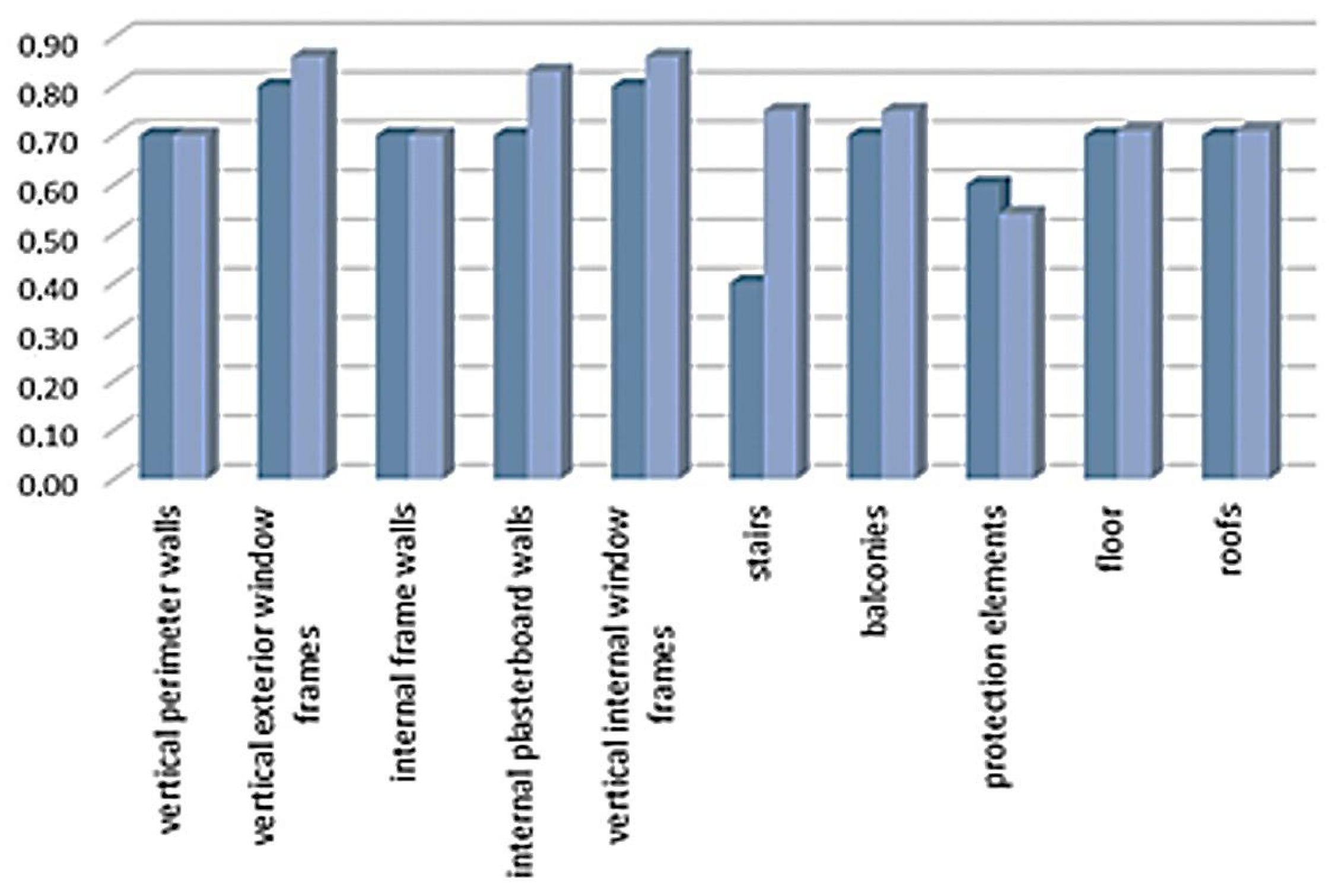
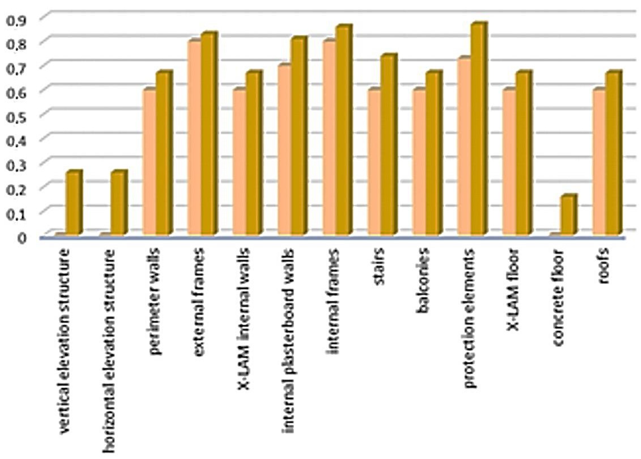
5.6. Assessment of the Level of Disassembly

The assessment was conducted using both the UNI method (11277:2008) and the integrated experimental method. Below is a comparison of the results obtained for both case studies.
Looking at the table and the graph (Table 16, Figure 13), three different situations can be traced: the LID score obtained with the integrated experimental method was higher than the score obtained with the UNI method, it was lower, or the two scores were equal.
Looking at the table and the graph (Table 17, Figure 14), all the technical elements scored were higher when using the integrated experimental method.

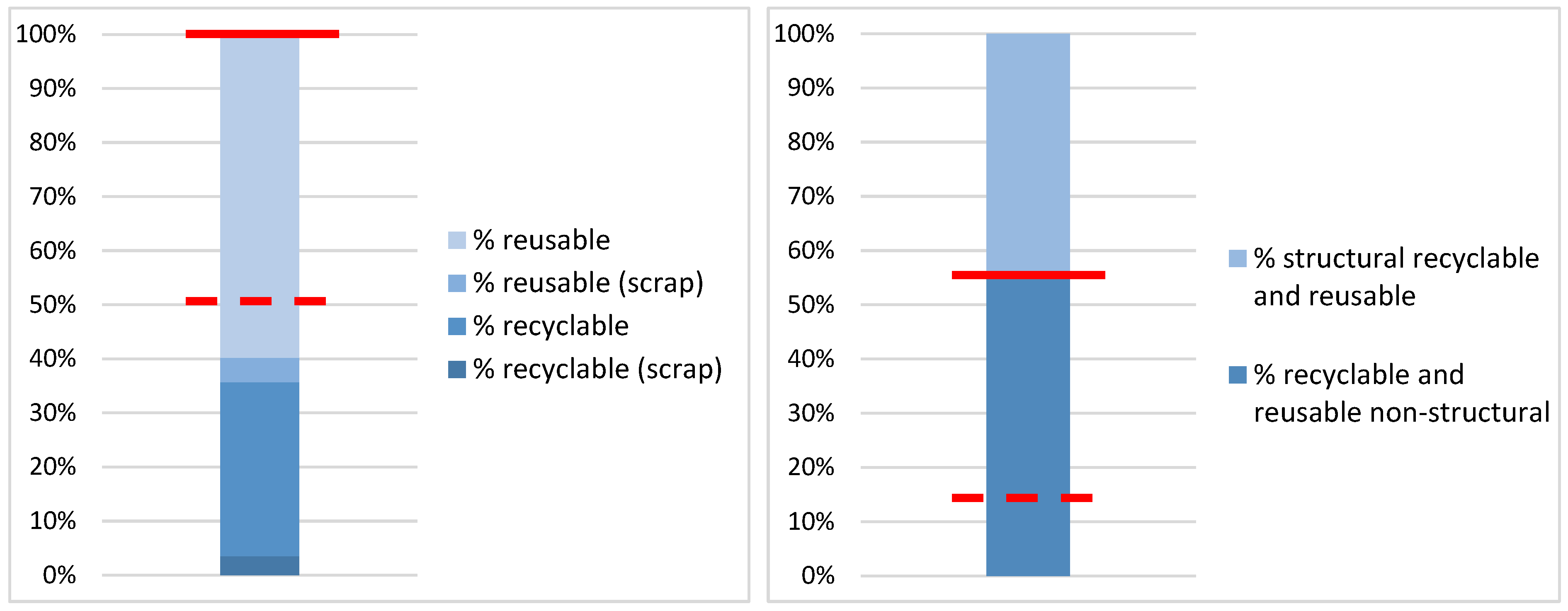
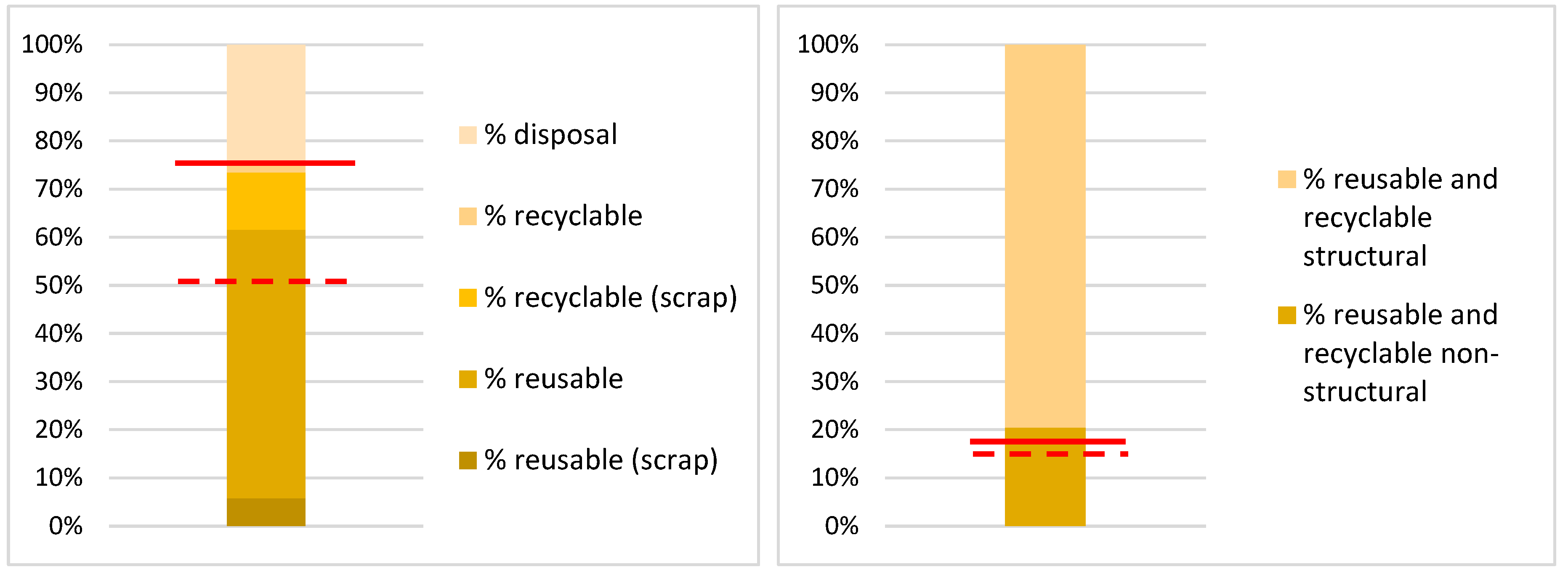
5.7. Estimation of Waste Streams and Quantities and Verification of CAM Parameters

The Italian CAM requires the following disassembly thresholds (criterion 2.4.1.1 “Disassembly” decree 11 October 2017) [42]:
At least 50 percent weight/weight of the building components and prefabricated elements excluding systems must be subject to selective demolition at end-of-life and be recyclable or reusable;
At least 15 percent of the above percentage must be non-structural materials.
The results in terms of the percentages of recyclable and reusable building components and prefabricated elements are shown below (Table 18 and Table 19, Figure 15 and Figure 16).
As shown in the graphs of Figure 15 and Figure 16, both case studies exceeded the two thresholds imposed by the Ministerial Decree. In particular, the Villa GP case study achieved a percentage of building components and prefabricated elements that can be recycled or reused of 100%, which was higher than the percentage achieved by the Via Cenni complex case study, being 75.25%. The first case study also achieved a higher percentage of recyclable or reusable building components and non-structural prefabricated elements. This value was 55.75% compared to 20.7% in the case of the Via Cenni complex.

6. Discussions

In summary, with reference to the goals set by the study, the application of the methodology to the investigated buildings allowed us to extrapolate two families of results:

6.1. CO2e Emissions of Module C and Consequent Benefits in Module D (UNI 15978)

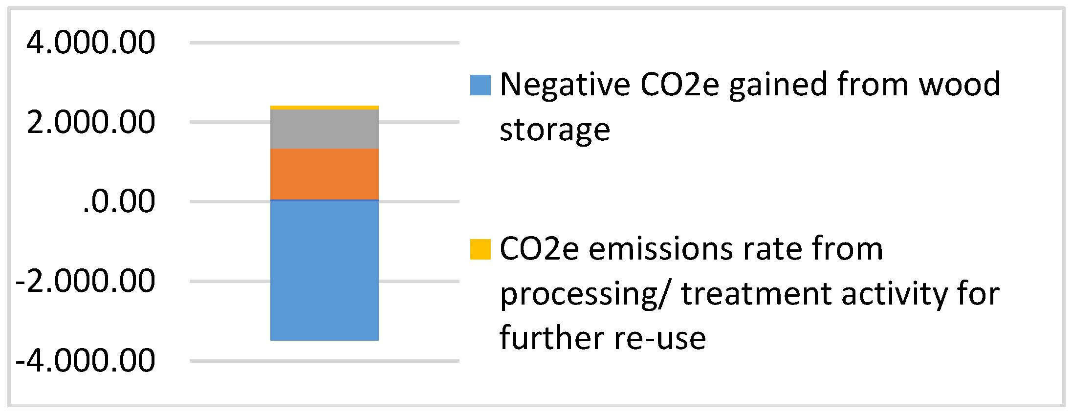
6.1.1. Villa GP: Discussion of Results, with Reference to the Application of Modules C and D

Module C of the Villa GP case study resulted in a unit emission of +2.916 kg CO2e/m3, from the perspective of obtaining a benefit (module D), in terms of emissions reduction, of −4.470 kg CO2e/m3, allowing for a negative balance in the transition from the cradle to the grave, estimated at −1.554 kg CO2e/m3.

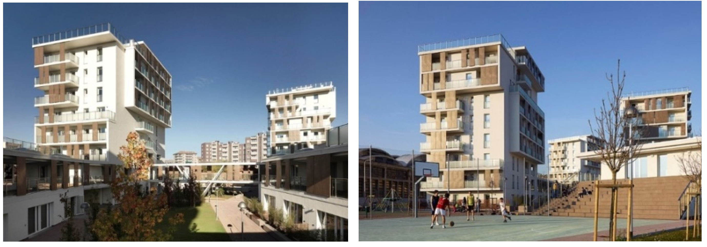
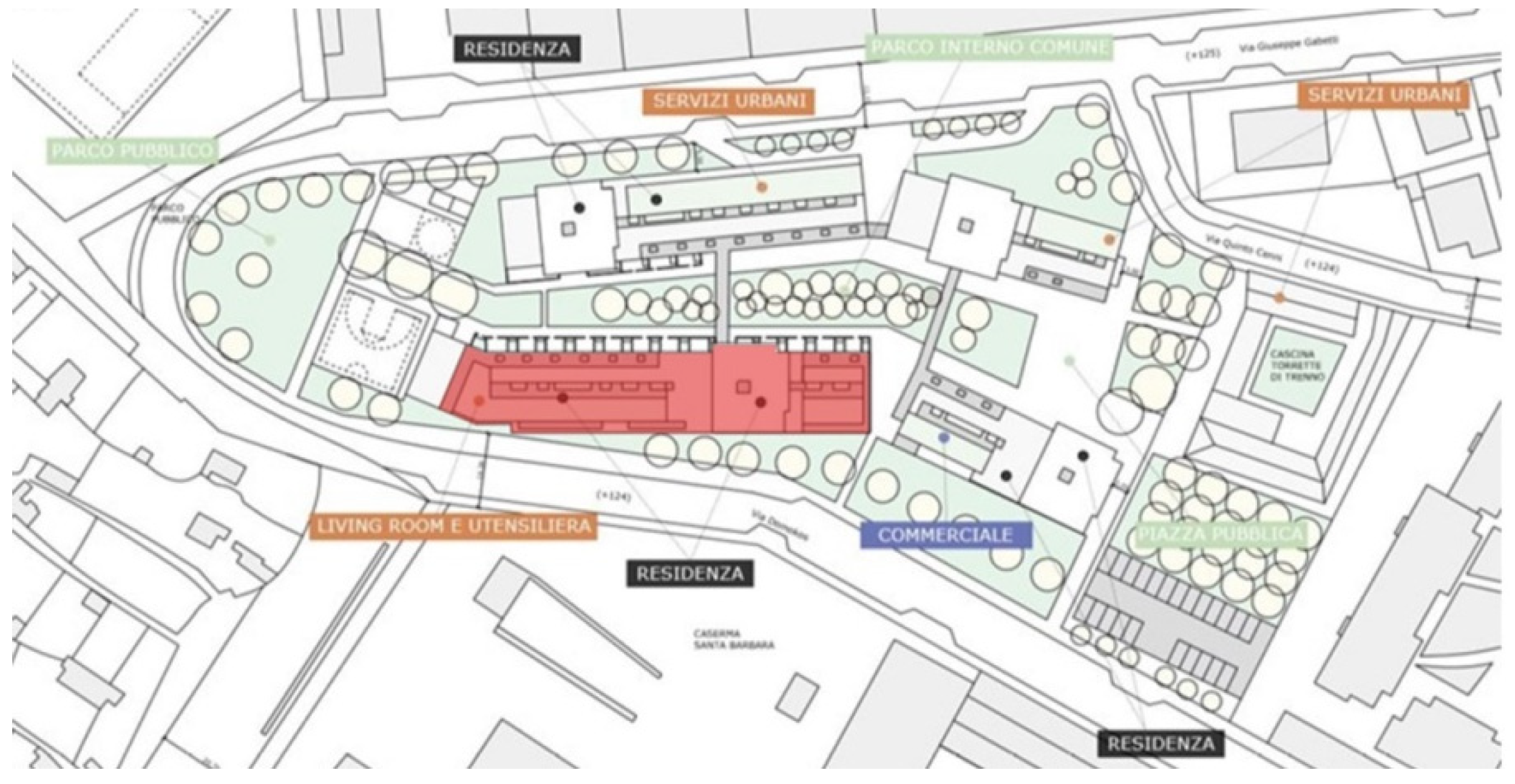
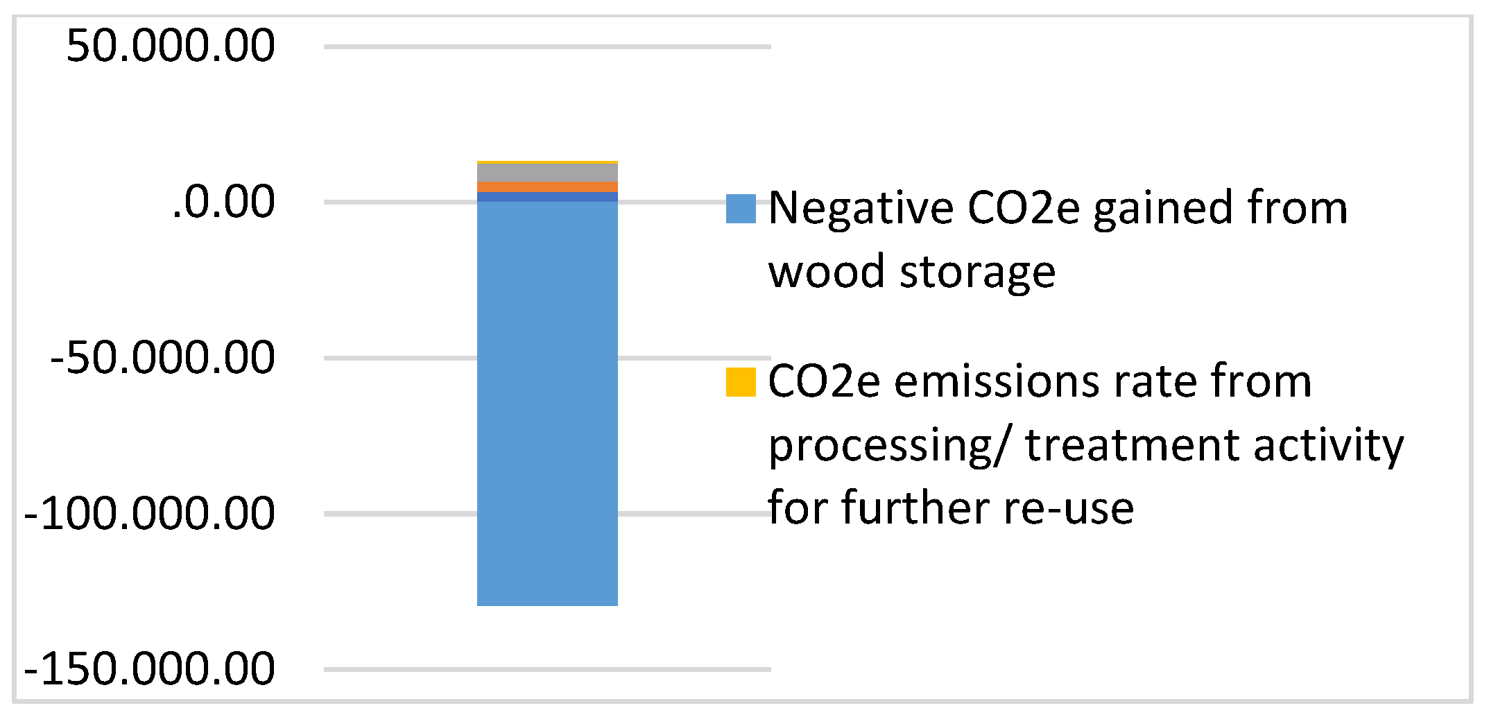
6.1.2. Via Cenni Complex: Discussion of Results, with Reference to the Application of Modules C and D

Module C of the Via Cenni complex case study resulted in a unit emission of +1.080 kg CO2e/m3 from the perspective of achieving a benefit (module D), in terms of emissions reductions, of −10.670 kg CO2e/m3, allowing for a negative balance in the transition from the cradle to the grave, estimated at −9.590 kg CO2e/m3.

6.2. Compliance with the Disassembly Threshold (Italian CAM)

6.2.1. Villa GP: Discussion of Results, with Reference to Italian CAM Compliance

The Villa GP case study, exceeds the minimum thresholds required by CAM, both in terms of the percentage of disassembly to total components (100% > 50%) and the incidence of non-structural components only (55.73% > 15%).

6.2.2. Via Cenni Complex: Discussion of Results, with Reference to Italian CAM Compliance

The Via Cenni complex case study exceeded the minimum thresholds required by CAM, both in terms of the percentage of disassembly potentiality out of the total components (75.25% > 50%), and the incidence of non-structural components only (15.41% > 15%). This second case also had a disposal rate, which was 24.75%.

6.3. Overall Considerations

The results show that the case studies present different values in terms of the goal to be pursued:
In terms of CO2e emissions, in the end-of-life phase, the Via Cenni complex presents a more virtuous construction system compared to Villa GP;
In terms of the disassembly potentiality, the Via Cenni complex, while exceeding both thresholds imposed by the Italian CAM, presented lower values compared to Villa GP as well as a residual amount of materials to be taken for disposal.
Therefore, the final emerging considerations are:
With regard to the level of CO2e emissions at the end-of-life, the case study of greater volume (Via Cenni complex) allowed us to optimize the use of machinery in the deconstruction and transport phases;
Regarding the level of disassembly potentiality, the XLAM construction system has more complex connections, and is therefore more difficult to be disassembled than a ‘frame’ construction system.

7. Conclusions

The construction sector, being responsible for 39% of carbon dioxide emissions [42], has a key role to play in achieving this goal. To change this trend, the construction sector needs to transform the life cycle assessment (LCA) pathway from linear to circular to ensure a more efficient use of natural resources.
The studies investigated in the state-of-the-art have not taken into account the potential of going beyond module C of BS EN 15978:2011 [5], and should be considered as partial works still linked to a linear vision. In contrast, closing the circle of processes is essential, and this goal is only possible by providing a series of strategies downstream of the demolition of a building system, preferably of a selective type, and the reintroduction of components/materials into a new ‘C2C—from Cradle to Cradle’ production cycle.
In order to pursue the transition from a linear to circular economy and to promote sustainable economic growth, a very important aspect to be considered is the management of construction and demolition waste (CDW). Article 11(2) of Directive 2008/98/CE [43] states that ‘preparation for re-use, recycling and other material recovery […] shall be increased to at least 70% by weight’, a target already achieved for C and D waste in 2011 and stood at 75.1% in 2017 [44]. With a view to maximizing the potential for the reuse of building components and thus reducing C and DW, both the design phase and the end-of-life phase of a building organism play a fundamental role.
In the design phase, a sustainable strategy oriented toward the reintroduction of materials into the production cycle is represented by the choice of dry technological systems rather than wet ones, as they are characterized by greater disassembly potentiality, and therefore favor the reuse of building components with the same function; in contrast, wet building systems allow for the reintroduction of components into the production cycle with different functions from the original ones, most of the time with lower performance, only following treatments that produce energy consumption [10].
In the end-of-life phase, a sustainable strategy oriented toward the reintroduction of materials into the production cycle foresees the preparation of a disassembly and selective demolition plan that allows for the reuse or recycling of materials, building components, and prefabricated elements used. The Italian CAM for Buildings (Minimum Environmental Criteria) [13] requires that at least 50 percent by weight of the building components must be recyclable or reusable, and of this percentage, at least 15 percent must be nonstructural materials.
The study developed a method to assess the environmental impact of the disassembly and selective demolition process by identifying the process with the lowest CO2e emissions to minimize waste at the end-of-life phase. The methodology was applied to two wooden architectures, whose materials are able to store CO2 due to their organic nature, which will be returned to the environment after incinerating (i.e., when no further life cycle is possible for it) [45].
As shown above, in both case studies (i.e., for both the frame and XLAM system), the final CO2e balance was negative due to the offsetting emission credit from the storage property of the wood components.
This research has shown that buildings designed with a predominantly wood construction system can make a significant contribution in terms of reducing the CO2e emissions throughout their life cycle. This is due to the following main aspects:
Easy selective demolition process, resulting in waste reduction and a high reuse rate of components at the end-of-life;
Consequent reduction in virgin raw material as a result of the system’s potential use at the end-of-life;
Possibility of reducing the overall emissions of the wooden building ( near zero) due to the carbon storage properties of the wooden components.

Author Contributions

Conceptualization, G.D.R.; Methodology, G.D.R.; Software, L.S.; Validation, G.D.R., R.M. and L.S.; Formal analysis, L.S.; Investigation, R.M. and L.S.; Resources, L.S.; Data curation, R.M. and L.S.; writing—original draft preparation, L.S.; Writing—review and editing, G.D.R.; Visualization, G.D.R. and R.M.; Supervision, G.D.R. All authors have read and agreed to the published version of the manuscript.

Funding

This research received no external funding.

Data Availability Statement

Conflicts of Interest

The authors declare no conflict of interest. The funders had no role in the study design, data collection, analysis, or interpretation, the writing of the manuscript, or the decision to publish the results.

References

  1. Communication from the Commission to the European Parliament, the Council, the European Economic and Social Committee and the Committee of the Regions ‘Fit for 55’: Delivering the EU’s 2030 Climate Target on the Way to Climate Neutrality COM(2021) 550 Final. Available online: https://eur-lex.europa.eu/legal-content/EN/TXT/PDF/?uri=CELEX:52021DC0550&from=EN (accessed on 10 April 2022).
  2. Giordano, R.; Serra, V.; Tortalla, E.; Aghemo, C. Embodied Energy and Operational Energy Assessment in the Framework of Nearly Zero Energy Building and Building Energy Rating. Energy Procedia 2015, 78, 3204–3209. [Google Scholar] [CrossRef] [Green Version]
  3. United Nations Environment Programme. 2022 Global Status Report for Buildings and Construction. Available online: https://globalabc.org/sites/default/files/2022-11/FULL%20REPORT_2022%20Buildings-GSR_1.pdf (accessed on 20 November 2022).
  4. Thormark, C. A low energy building in a life cycle—Its embodied energy, energy need for operation and recycling potential. Build. Environ. 2002, 37, 429–435. [Google Scholar] [CrossRef]
  5. BS EN 15978:2011; Sustainability of Construction Work—Sassessment of Environmental Performance of Buildings—Calculation Method (Incorporating Corrigendum November 2011). British Standards Institution: London, UK, 2011. Available online: https://www.greenbooklive.com/filelibrary/EN_15804/PN326-BRE-EN-15978-Methodology.pdf (accessed on 20 January 2020).
  6. Wu, H.J.; Yuan, Z.W.; Zhang, L.; Bi, J. Life cycle energy consumption and CO2 emission of an office building in China. Int. J. Life Cycle Assess 2012, 17, 105–118. [Google Scholar] [CrossRef]
  7. Bontempi, E. How to perform a material recovery sustainability evaluation preliminary to LCA? Resour. Environ. Sustain. 2022, 9, 100074. [Google Scholar] [CrossRef]
  8. Rabani, M.; Madessa, B.H.; Ljungström, M.; Aamodt, L.; Løvvold, S.; Nord, N. Life cycle analysis of GHG emissions from the building retrofitting: The case of a Norwegian office building. Build. Environ. 2021, 204, 108159. [Google Scholar] [CrossRef]
  9. Di Ruocco, G.; Melella, R.; Marino, V. An integrated assessment method for the sustainability of the opaque building envelope in residential buildings with Italian GBC-HOME certification. Archit. Eng. Des. Manag. 2021, 18, 545–570. [Google Scholar] [CrossRef]
  10. Di Ruocco, G.; Melella, R.; Cucco, P.; Capuano, C. Sustainable strategies for the recovery and conservation of historical buildings. LCA approach for CO2e reduction. Sustain. Mediterr. Constr. 2021, 127–132. Available online: http://www.sustainablemediterraneanconstruction.eu/SMC/The%20Magazine%20n.14_files/1416.pdf (accessed on 10 January 2022).
  11. Gomes, R.; Dinis Silvestre, J.; de Brito, J. Environmental, economic and energy life cycle assessment “from cradle to cradle” (3E-C2C) of flat roofs. J. Build. Eng. 2020, 32, 101436. [Google Scholar] [CrossRef]
  12. Jones, C.I.; Hammond, G. Embodied energy and carbon in construction materials. Proc. ICE Energy 2008, 161, 87–98. [Google Scholar] [CrossRef] [Green Version]
  13. Italian Ministerial Decree 11/10/2017—Criteri Ambientali Minimi (Minimum Environmental Criteria) for the Contracting of Design and Works Services for New Construction, Renovation and Maintenance of Public Buildings, Ministry of Environment and Land and Sea Protection. Available online: https://www.gazzettaufficiale.it/eli/gu/2017/11/06/259/sg/pdf (accessed on 2 January 2020).
  14. Data Sheet for Impact Wrench HILTI SIW 22T-A 1/2″. Available online: https://www.hilti.it/c/CLS_POWER_TOOLS_7124/CLS_IMPACT_DRIVERS_WRENCHES_7124/CLS_CORDLESS_IMPACT_WRENCHES_7124/r4265 (accessed on 8 April 2021).
  15. Data Sheet for Impact Wrench HILTI SID 8-A22. Available online: https://www.hilti.it/c/CLS_POWER_TOOLS_7124/CLS_IMPACT_DRIVERS_WRENCHES_7124/CLS_CORDLESS_IMPACT_DRIVERS_7124/r4659308 (accessed on 8 April 2021).
  16. Data Sheet for Demolition Hammer HILTI 3000-AVR. Available online: https://www.hilti.it/c/CLS_POWER_TOOLS_7124/CLS_DEMOLITION_HAMMER_BREAKER_SUB_7124/CLS_DEMOLITION_HAMMER_BREAKER_7124/r9671577 (accessed on 8 April 2021).
  17. Data Sheet for Demolition Hammer HILTI TE 700-AVR SDS MAX. Available online: https://www.hilti.it/c/CLS_POWER_TOOLS_7124/CLS_DEMOLITION_HAMMER_BREAKER_SUB_7124/CLS_DEMOLITION_HAMMER_BREAKER_7124/r5005 (accessed on 8 April 2021).
  18. Italian Standard UNI 8290/1-1981; Residential Building—Technological System—Classification and Terminology. Available online: https://store.uni.com/uni-8290-1-1981-a122-1983 (accessed on 17 December 2020).
  19. Construction. Needs of the End-User. Classification, Italian Standard UNI 8289-1981. Sustainability in Construction-Needs and Requirements of Environmental Compatibility of Residential Projects and Similar, Offices and Similar, of New Construction and Renovation, Italian Standard UNI 11277-2008. Available online: http://store.uni.com/catalogo/uni-11277-2008 (accessed on 17 December 2020).
  20. Norma UNI 11228-1:2009; Ergonomia-Movimentazione Manuale—Parte 1: Sollevamento e Trasporto. Available online: http://store.uni.com/catalogo/uni-iso-11228-1-2009 (accessed on 17 December 2020).
  21. Data Sheet for Vertical Lift—ALIMAK HEK TPL 2000. Available online: https://www.archiproducts.com/it/prodotti/alimak/elevatore-da-cantiere-hek-tpl-2000-2000-d-1800_80122 (accessed on 12 April 2021).
  22. Data Sheet for Telescopic Handler—JCB 525-60E. Available online: https://www.jcb.com/it-it/products/movimentatori-telescopici/525-60e-hi-viz (accessed on 12 April 2021).
  23. Data Sheet for Telescopic Handler—JCB 541-70. Available online: https://www.jcb.com/it-it/products/movimentatori-telescopici/541-70 (accessed on 12 April 2021).
  24. Data Sheet for Telescopic crane—LIEBHER LTM 1040-2.1. Available online: https://www.lectura-specs.it/it/modello/gru/gru-fuoristrada-971405-liebherr/ltm-1040-2-1-1148034 (accessed on 12 April 2021).
  25. Data Sheet for Self-Moving Vertical Platform—GENIE GS-4655. Available online: https://www.genielift.com/it/aerial-lift-products/Slab-scissor-lifts/gs-4655 (accessed on 14 April 2021).
  26. Data Sheet for Self-Moving Vertical Platform with Telescopic Arm—GENIE SX-105 XC. Available online: https://www.genielift.com/it/aerial-lift-products/telescopic-boom-lifts/sx-105-xc (accessed on 14 April 2021).
  27. Film Corresponding to a Real Case. Connection of the Element to the Crane Hook: XLAM Wooden House Construction in 12 Days. Available online: https://www.youtube.com/watch?v=gh4-V2tIq84&t=418s (accessed on 14 April 2021).
  28. Mayer, M.; Bechthold, M. Development of policy metrics for circularity assessment in building assemblies. Econ. Policy Energy Environ. 2018, 1, 57–84. [Google Scholar] [CrossRef]
  29. Film Corresponding to a Real Case. Loading the Elevator Basket. Available online: https://www.youtube.com/watch?v=6WZscEY4OCk&t=2s&ab_channel=AlimakHek (accessed on 18 April 2021).
  30. Film Corresponding to a Real Case. Loading a Truck with a Telescopic Crane. Available online: https://www.youtube.com/watch?v=YDp6NROFVsc&t=409s&ab_channel=ISOLPANCOSTRUZIONIINLEGNO (accessed on 18 April 2021).
  31. Film Corresponding to a Real Case. Loading a Lorry with a Mover. Available online: https://www.youtube.com/watch?v=LWbV3u7VLRQ&t=73s&ab_channel=LaorencHoxha (accessed on 18 April 2021).
  32. The Environmental Performance in Construction (EPiC), University of Melbourne. Available online: https://msd.unimelb.edu.au/research/projects/current/environmental-performance-in-construction/about (accessed on 17 December 2020).
  33. COMMISSION DECISION of 18 December 2014 Amending Decision 2000/532/EC on the List of Waste Pursuant to Directive 2008/98/EC of the European Parliament and of the Council (Text with EEA Relevance) (2014/955/EU). Available online: https://eur-lex.europa.eu/legal-content/EN/TXT/PDF/?uri=CELEX:32014D0955&from=EN (accessed on 17 December 2020).
  34. Data Sheet for Circular Table Saw—Bosch GTS 10 XC PROFESSIONAL. Available online: https://www.bosch-professional.com/it/it/products/gts-10-xc-0601B30400 (accessed on 22 April 2021).
  35. Data Sheet for CNC Machining Centre—BIESSE Uniteam UT. Available online: https://www.biesse.com/it/legno/centri-di-lavoro/uniteam-ut (accessed on 22 April 2021).
  36. Data Sheet for Electric Planer—FELDER GROUP FORMAT 4 Plan 51 L. Available online: https://www.felder-group.com/it-it/prodotti/pialle-a-filo-e-spessore-c1948/pialla-a-filo-plan-51l-p3272 (accessed on 22 April 2021).
  37. Data Sheet for Spray Gun—WAGNER Airless Sprayer Control Pro 350 M. Available online: https://www.wagner-group.com/it/fai-da-te/prodotti-accessori/prodotto/airless-sprayer-control-pro-350-m/ (accessed on 22 April 2021).
  38. Longo, D. Decostruzione e Riuso: Procedure e Tecniche di Valorizzazione dei Residui Edilizi in Italia; Alinea Editrice s.r.l.: Firenze, Italy, 2007; ISBN 8860551226. [Google Scholar]
  39. European Commission: EU Construction and Demolition Waste Management Protocol—29/09/2016. Available online: https://ec.europa.eu/docsroom/documents/20509/ (accessed on 18 July 2021).
  40. European Commission: Guidelines for the Waste Audits before Demolition and Renovation Works of Buildings. EU Construction and Demolition Waste Management. 2018. Available online: https://ec.europa.eu/docsroom/documents/31521 (accessed on 20 October 2022).
  41. United Nations General Assembly—Transforming Our World: The 2030 Agenda for Sustainable Development. Available online: https://www.un.org/en/development/desa/population/migration/generalassembly/docs/globalcompact/A_RES_70_1_E.pdf (accessed on 20 October 2022).
  42. GlobalABC, 2019 Global Status Report for Buildings and Construction—Towards a Zero-Emissions, Efficient and Resilient Buildings and Construction Sector. 1 January 2020. Available online: https://globalabc.org/resources/publications/2019-global-status-report-buildings-and-construction (accessed on 5 March 2021).
  43. Direttiva 2008/98/CE del Parlamento Europeo e del Consiglio del 19 Novembre 2018 Relativa ai Rifiuti e che Abroga Alcune Direttive. Available online: https://eur-lex.europa.eu/legal-content/IT/TXT/?uri=celex:32008L0098 (accessed on 5 March 2021).
  44. Annuario dei Dati Ambientali—Rifiuti, ISPRA. 2019. Available online: https://www.isprambiente.gov.it/files2020/pubblicazioni/stato-ambiente/annuario-2020/11Rifiuti2019.pdf (accessed on 10 January 2021).
  45. Van Der Lugt, P. Carbon Storage Utilising Timber Products. Enviromental Ind. Mag. 2012, 76–80. Available online: https://research.tudelft.nl/en/publications/carbon-storage-utilising-timber-products (accessed on 18 July 2021).
Figure 1. Linear economy, cradle-to-grave process.
Buildings 13 00157 g001
Figure 2. Circular economy, cradle-to-cradle process.
Buildings 13 00157 g002
Figure 3. Building assessment information (Source: BS EN 15978:2011).
Buildings 13 00157 g003
Figure 4. Villa GP, IRODA Studio (Source: legnoarchitettura).
Buildings 13 00157 g004
Figure 5. Via Cenni complex.
Buildings 13 00157 g005
Figure 6. Setting of the chosen building.
Buildings 13 00157 g006
Figure 7. Case study: Villa GP. Total emissions, in terms of kg, of each of the five rates.
Buildings 13 00157 g007
Figure 8. Case study: Via Cenni complex. Total emissions, in terms of kg, of each of the five rates.
Buildings 13 00157 g008
Figure 9. CO2e,1 emissions from the demolition activity for Villa GP (left) and the Via Cenni complex (right).
Buildings 13 00157 g009
Figure 10. CO2e,2 emissions from scrap resulting from demolition operations for Villa GP (left) and the Via Cenni complex (right).
Buildings 13 00157 g010
Figure 11. CO2e,3 emissions from off-site transport for Villa GP (left) and Via Cenni complex (right).
Buildings 13 00157 g011
Figure 12. CO2e,4 emissions from transformation/treatment for further reuse for Villa GP (left) and the Via Cenni complex (right).
Buildings 13 00157 g012
Figure 13. Case study: Villa GP. Comparison of LID scores.
Buildings 13 00157 g013
Figure 14. Case study: Via Cenni complex. Comparison of LID scores.
Buildings 13 00157 g014
Figure 15. Case study Villa GP: Achievement of 50% by weight threshold of total quantity, recyclable, or reusable building and prefabricated components (left); achievement with the 15% by weight threshold of non-structural, recyclable, or reusable building and prefabricated components (right).
Buildings 13 00157 g015
Figure 16. Case study of the Via Cenni complex: Achievement of 50% by weight threshold of the total quantity, recyclable, or reusable building and prefabricated components (left); achievement with the 15% by weight threshold of the non-structural, recyclable, or reusable building and prefabricated components (right).
Buildings 13 00157 g016
Table 1. Tools used for removing connections.
Connection TypeToolsModel
NailingNail extractorINNOVA
BoltsImpact wrenchHILTI-SIW 22T-A 1/2″ [14]
ScrewingImpact wrenchHILTI-SID 8-A 22 [15]
Snap-in joints and/or snap-in jointsManual disassembly/
Simple overlappingManual disassembly/

Hydraulic and air binders

Demolition hammer
HILTI 3000-AVR for concrete slabs [16]
HILTI—TE 700 SDS MAX for plaster and tiles [17]
Table 2. Equipment used for the ground transportation of elements.
Ground Floor
Weight (P) and Size (L) of ElementsGround Transport ModesMachinesModel
P < 25 kg
L < 3.2 m
Manual ground transport//
P < 25 kg
L > 3.2 m
Manual ground transport//
P > 25 kg
L < 3.2 m
Ground transport in group of elements (P < 2000 kg) inside the elevator basketElevatorALIMAK HEK—TPL 2000
P > 25 kg
L > 3.2 m
Ground transport of the single element by telescopic craneTelescopic craneLIEBHER—LTM 100-2.1
XLAM panel and framed panelGround transport of the single element by telescopic craneTelescopic craneLIEBHER—LTM 100-2.1
Next Floor
P < 25 kg
L < 3.2 m
Ground transport in group of elements (P < 2000 kg) inside the elevator basketElevatorALIMAK HEK—TPL 2000
P < 25 kg
L > 3.2 m
Ground transport of the single element by telescopic craneTelescopic craneLIEBHER—LTM 100-2.1
P > 25 kg
L < 3.2 m
Ground transport in group of elements (P < 2000 kg) inside the elevator basketElevatorALIMAK HEK—TPL 2000
P > 25 kg
L > 3.2 m
Ground transport of the single element by telescopic craneTelescopic craneLIEBHER—LTM 100-2.1
XLAM panel and framed panelGround transport of the single element by telescopic craneTelescopic craneLIEBHER—LTM 100-2.1
Table 3. Equipment used for loading onto the trucks and/or tractor-trailers of items.
Weight (P) and Size (L) of ElementsGround Transport ModesMachinesModel
P < 25 kg
L < 4.00 kg
Manual loading on truck//
P < 25 kg
L > 4.00 m
Manual loading on truck//
P > 25 kg
L < 4.00 m
Loading a group of elements anchored to the fork of a telescopic handler on truckTelescopic handlerJCB—525-60E (P < 2000 kg)
JCB—541-70 (P < 4100 kg)
P > 25 kg
L > 4.00 m
Loading the single element with a telescopic crane on trackTelescopic craneLIEBHER—LTM 1040-2.1
XLAM panel and framed panelLoading the single element with a telescopic crane on trackTelescopic craneLIEBHER—LTM 1040-2.1
Table 4. Equipment used for the removal of air connections.
Works at HeightMachinesModel
Maximum indoor working height 15.95 m
Maximum outdoor working height 8.55 m
Self-moving vertical platformGENIE—GS 4655
Maximum working height 34 mSelf-moving vertical platform with telescopic armGENIE—SX-105 XC
Table 5. Seconds needed to remove a single connection.
Tools and MachinesTime Required to Remove a Single Connection Source
Nail extractor10 < s < 40 Data collected in literature [28]
Impact wrenchs < 10Data collected in literature [28]
Manual disassemblys < 10Data collected in literature [28]
Demolition hammer2.4 m3/hData sheet [16]
Demolition hammer0.072 m3/hData sheet [17]
Table 6. CO2e emissions generated using tools to remove connections.
ToolOperating Seconds or Maximum CapacityRemoved Connections or VolumeTool ConsumptionEmission FactorCO2e
Emissions
Nail extractorSn-0.01 kg CO2e/hkg CO2e
Impact wrenchSn0.11 kWh0.44 kg CO2e/hkg CO2e
Demolition hammer for slabh/m3m30.97 kWh0.44 kg CO2e/hkg CO2e
Table 7. CO2e emissions generated using machinery for ground transportation and loading onto trucks and/or articulated trucks of an item or group of items.
MachineOperating SecondsNumber of TripsMachine ConsumptionEmission FactorCO2e
Emissions
Self-moving vertical platformsn7.20 kWh0.44 kg CO2e/kWhkg CO2e
Self-moving vertical platform with telescopic armsn3.94 L/h2.64 kg CO2e/L dieselkg CO2e
Elevatorsn12.16 kW0.44 kg CO2e/kWhkg CO2e
Telescopic cranesn15.14 L/h2.64 kg CO2e/L dieselkg CO2e
Telescopic handlersn5.1 L/h2.64 kg CO2e/L dieselkg CO2e
Telescopic handlersn24 kWh0.44 kg CO2e/kWkg CO2e
Table 8. Explanatory table for the calculation of the reusability index.
0%80%90%100%
Wet systemAdhesive systemDry system with clamping technologyDry system with interlocking technique
Hydraulic and air bindersFusion adhesives, evaporation adhesivesNailing, bolting, screwingSimple overlapping, snap-in
Table 9. Speed required to carry out the operations.
ActivitiesMachinesModelSpeed (m/s)
Removal of perforated partsCircular table sawBOSCH—GTS 10 XC PROFESSIONAL0.017
Removal of perforated partsElectric circular sawBIESSE—UNITEAM UT0.14
Removal of surface materialElectric planerFORMAT 4—plan 51 L0.033
Impregnation treatmentSpray gunWAGNER—Airless Sprayer Control Pro 350 M7.5 m2/min
Table 10. CO2e emissions from the processing activities for subsequent reuse.
Processing ActivitiesElement DimensionsNumber of ActivitiesSpeedPowerEmission FactorCO2e Emissions
Cutting with a circular table sawmNh/m2.1 kW0.44 kg CO2e/kWhkg CO2e
Cutting with electric circular sawmNh/m22 kW0.44 kg CO2e/kWhkg CO2e
PlaningmNh/m5.5 kW0.44 kg CO2e/kWhkg CO2e
Impregnation spray treatmentm2Nh/m20.6 kW0.44 kg CO2e/kWhkg CO2e
Table 11. Classification of the level of disassembly (LID) (Source: UNI 11277:2008).
Building SystemLaying TechnologyLID
Wet systemHydraulic and air binders0
Adhesive systemFusion adhesives, evaporation adhesives0
Dry system with clamping techniqueNailing, bolting, screwing3
Dry system with interlock techniqueSnap-in3
Dry system with juxtaposition techniqueSimple overlapping5
Table 12. Integrated experimental method.
Building System and Laying Technology
p = 0.60
Damage Caused by Handling and Transport
p = 0.20
Processing Activities
p = 0.20
Wet system—hydraulic and air binders|0%Fragile elements, high probability of damage|20%Non-reusability|0%
Adhesive system—fusion adhesives, evaporation adhesives|25%Transport to the ground and loading onto a lorry, L > 14 m|40%Cutting of perforated parts|25%
Dry system with clamping technique—nailing|50%Transport to the ground and loading onto a lorry, L < 14 m|40%Planing|50%
Dry system with clamping technique—bolting, screwing|75%Ground transportation with lifting devices|60%Impregnating spray treatment|75%
Dry system with interlock and juxtaposition technique—snap and simple interlocking|100%Manual transport|100%General cleaning|100%
Table 13. Case study: Villa GP. Total emissions, in terms of kg, of each of the five rates.
CO2e emissions rate from demolition activity64.12 kg CO2e
CO2e emissions rate from scrap resulting from demolition activities1272.96 kg CO2e
CO2e emissions rate from off-site transport989.15 kg CO2e
CO2e emissions rate from transformation/treatment activity for further re-use80.55 kg CO2e
Negative CO2e gained from wood storage−3489.65 kg CO2e
∑CO2e emissions−1082.87 kg CO2e
Table 14. Case study: Via Cenni complex. Total emissions, in terms of kg, of each of the five rates.
CO2e emissions rate from demolition activity3292.76 kg CO2e
CO2e emissions rate from scrap resulting from demolition activities3328.82 kg CO2e
CO2e emissions rate from off-site transport5812.66 kg CO2e
CO2e emissions rate produced by processing/treatment activity for further reuse663.37 kg CO2e
Negative CO2e emissions gained from wood storage−129,437.17 kg CO2e
∑CO2e emissions−116,339.56 kg CO2e
Table 15. CO2e,5 positive and negative emission factors: absolute, expressed in Kg CO2e (left) and relative to the functional unit, expressed in Kg CO2e/m3 (right).
Villa GP
Emission positive rate+2406.78 kg CO2e+2.916 kg CO2e/m3
Negative rate gained from wood storage−3689.65 kg CO2e−4.470 kg CO2e/m3
Via Cenni Complex
Emission positive rate+13,097.61 kg CO2e+1.080 kg CO2e/m3
Negative rate gained from wood storage−129,437.17 kg CO2e−10.670 kg CO2e/m3
Table 16. Case study: Villa GP. Comparison of LID scores.
Technical ElementLID—UNI MethodLID—Experimental Method
Vertical perimeter walls0.700.70
Vertical exterior windows frames0.800.86
Internal frame walls0.700.70
Internal plasterboard walls0.700.83
Vertical internal windows frames0.800.86
Stairs0.400.75
Balconies0.700.75
Protection elements0.600.54
Floor0.700.71
Roofs0.700.71
Table 17. Case study: Via Cenni complex. Comparison of LID scores.
Technical ElementLID—UNI MethodLID—Experimental Method
Vertical elevation structure00.26
Horizontal elevation structure00.26
Perimeter walls0.600.67
External frames0.800.83
XLAM internal walls0.600.67
Internal plasterboard walls0.700.81
Internal frames0.800.86
Stairs0.600.74
Balconies0.600.67
Protection elements0.730.87
XLAM floor0.600.67
Concrete floor00.16
Roofs 0.600.67
Table 18. Case study: Villa GP. Percentages of the recyclable and reusable building components and prefabricated elements.
Total Waste Generated That Can Be Reused and Recycled—Villa GPPercentTotalNon Structural
Quantity of reusable material—structural materials39.84%100% (>50%)
Quantity of reusable material (scrap)—structural materials4.43%
Quantity of reusable material—non-structural materials19.98%55.73% (>15%)
Quantity of reusable material (scrap)—non-structural materials0.08%
Quantity of recyclable material (scrap)—non-structural materials3.57%
Quantity of recyclable material—non-structural materials32.10%
Table 19. Case study: Via Cenni complex. Percentages of the recyclable and reusable building components and prefabricated elements.
Total Waste Generated That Can Be Reused and Recycled—Via Cenni ComplexPercentTotalNon Structural
Quantity of reusable material—structural materials54.12%75.25% (>50%)
Quantity of reusable material (scrap)—structural materials5.73%
Quantity of reusable material—non-structural materials1.63%15.41% (>15%)
Quantity of reusable material (scrap)—non-structural materials0.06%
Quantity of recyclable material (scrap)—non-structural materials11.92%
Quantity of recyclable material—non-structural materials1.80%
Quantity of material to be discarded24.75%24.75%
Disclaimer/Publisher’s Note: The statements, opinions and data contained in all publications are solely those of the individual author(s) and contributor(s) and not of MDPI and/or the editor(s). MDPI and/or the editor(s) disclaim responsibility for any injury to people or property resulting from any ideas, methods, instructions or products referred to in the content.

