Article

Analyses of Structural Robustness of Prefabricated Modular Buildings: A Case Study on Mid-Rise Building Configurations

by
Thisari Munmulla
1,2,
Satheeskumar Navaratnam
1,*,
Julian Thamboo
3,
Thusiyanthan Ponnampalam
4,
Hidallana-Gamage Hasitha Damruwan
2,
Konstantinos Daniel Tsavdaridis
5 and
Guomin Zhang
1
1
School of Engineering, RMIT University, Melbourne, VIC 3000, Australia
2
Department of Civil Engineering, University of Moratuwa, Moratuwa 10400, Sri Lanka
3
Department of Civil Engineering, South-Eastern University of Sri Lanka, Oluvil 32360, Sri Lanka
4
Ronnie & Koh Consultants Pte. Ltd., Singapore 573972, Singapore
5
Department of Civil Engineering, School of Science and Technology, University of London, Northampton Square, London EC1V 0HB, UK
*
Author to whom correspondence should be addressed.
Buildings 2022, 12(8), 1289; https://doi.org/10.3390/buildings12081289
Submission received: 12 July 2022 / Revised: 4 August 2022 / Accepted: 15 August 2022 / Published: 22 August 2022
(This article belongs to the Section Building Energy, Physics, Environment, and Systems)

Abstract

:
The limited knowledge of the behaviour of modular buildings subjected to different loading scenarios and thereby lack of design guidelines hinder the growth of modular construction practices despite its widespread benefits. In order to understand the robustness of modular building systems, a case study was carried out using the numerical analysis method to evaluate the robustness of ten-storey braced frame modular buildings with different modular systems. Two types of modules with different span lengths were used in the assessments. Then, three different column removal scenarios involving (1) removal of a corner column, (2) an edge column, and (3) an interior column were employed to assess the robustness of modular building cases considered. The forces generated in the elements in close proximity to the removed column were verified to assess the robustness of each building case analysed. The results showed that the change in damping ratio from 1% to 5% has no significant influence on the robustness of the modular building cases considered, where the zero-damping leads to collapse. Corner column removal has not considerably affected the robustness of the braced modular building cases studied. The axial capacity ratio of columns is 0.8 in dynamic column removal in the building subjected to corner column removal, while in interior column removal capacity ratio reached up to 1.2, making it the most vulnerable failure scenario. Doubling the span of the modules (from 2.5 m to 5 m) has influenced the robustness of the buildings by increasing the axial forces of columns up to 30% in the interior column removal scenario. Thus, this study highlights that proper guidelines should be made available to assess the robustness of modular building systems to effectively design against progressive collapse.

1. Introduction

Prefabricated modular building construction is increasingly becoming popular over conventional building construction techniques, owing to various advantages: facilitating rapid construction, thereby reducing the construction time/cost, minimising on-site labour and wastages, and enabling better quality control in the construction [1,2,3]. Further, recent studies in terms of life-cycle sustainability performances also indicate that modular construction systems can be designed to minimise the overall life-cycle indices compared to conventional construction systems [4,5,6]. A modular building system primarily consists of prefabricated units (referred to as “modules”) and components (e.g., connections) that are transported and assembled on-site to erect the intended building configurations [7]. Although steel-based modular units and components are the most popular, there are hybrid modular systems available with steel, concrete, timber, etc. [8,9,10,11,12]. Moreover, conventional construction systems, which have not received significant attention in the past, have also developed through prefabrication in recent years [13]. Subsequently, ever-increasing housing demand and the requirement for rapid construction of infrastructures due to various disasters imply that the modular building system would be an inevitable construction choice in the future [14,15,16].
Although the concept of modular building has been around for some time, the approaches followed to design modular building systems are mostly based on the principles of designing conventional buildings. However, there are distinct features in modular building systems compared to conventional building systems, where they need systematic verifications in the designing and analysis phases [17,18,19,20]. Predominantly, modular building systems can be categorised into two types; they are (1) loadbearing modules and (2) frame-supported modules. In the loadbearing module system, the gravity actions are transferred through the loadbearing walls in the modules. Conversely, the loading effects are transferred through edge beams connected to corner posts in the frame-supported modular system. However, in either system, adequate bracing or diaphragm action should be made to resist lateral loading effects [21,22,23]. Moreover, depending on the category used, both the intra-module and inter-module connection types of the modular building systems exist among the buildings [24,25]. Thus, they make the design and analyses of the modular system different from the conventional buildings.
Nonetheless, few attempts have been made to develop design guidelines for modular buildings in recent times [18,26,27]. For example, a handbook published by Murray-Parkes et al. [28] provided technical guidance for the design of modular structures. However, most of these guidelines are still at the conceptual stage, and hence there need to be more systematic studies to develop comprehensive design standards for modular building systems, especially as the design guidelines to assess the robustness of the modular buildings are not well assessed. Thus, in this study, the focus was given to numerically assessing the robustness of the modular building systems.
The robustness of a building can be evaluated through progressive collapse analyses [29,30]. The local failure of a single element of the structure, which leads to a global failure of the entire structure or a disproportionate part of the structure, is identified as progressive collapse. GSA 2016 [31] guideline defines progressive collapse as “an extent of damage or collapse that is disproportionate to the magnitude of the initiating event”.
The collapses of major buildings due to abnormal loads in the recent past have brought the attention of the design engineers to study more about the robustness of the buildings to prevent progressive collapses. The collapse of Champlain Towers South in Florida, Rana Plaza in Bangladesh and World Trade Centre buildings in the USA can be considered as some of the major progressive collapse scenarios to occur in the recent past [32,33,34]. Continuity, alternate load paths and local resistance approaches are used in the designs to prevent the buildings from progressive collapse scenarios. These methods will only be productive in the prevention of disproportionate collapses [35]. The alternate load path method, which redistributes the forces of the damaged elements, is nowadays widely used in collapse analyses due to its lower complexity [36].
Therefore, the robustness of the modular buildings mainly relies on the nature of inter-modular connections used in the building [37], and the tendency of collapse in the modular building under abnormal loading is relatively higher and more complex than the conventional structures [38]. Hence, the analysis of the modular building performance corresponding to progressive collapse is highly recommended to avoid any potential failures of those building systems. Thus, it can be said that the studies related to progressive collapse characteristics of modular building systems, and thereby the robustness characteristics, have not been well investigated in the past. Therefore, in order to better understand the behaviour of modular buildings under progressive collapse scenarios, different modular building configurations were considered, and their robustness was numerically analysed using the SAP2000 [39] finite element programme. The details of the modular building cases and the analysis procedures are outlined in Section 2 and Section 3 of this paper, respectively. Section 4 gives the results of the collapsed scenarios considered and a detailed discussion in relation to the robustness of those building cases. Finally, the key conclusions derived from the assessments are summarised in Section 5.

2. Case Study Buildings Design

The alternative load path method was used to assess the progressive collapse mechanisms and robustness of the modular buildings in this study. The robustness of the modular building to prevent progressive collapse was investigated through linear static, nonlinear static, and nonlinear dynamic analyses using SAP2000 [39]. Two ten-storey braced modular buildings with the height of 35.4 m were selected as the case study buildings (see Figure 1a,b); they are named as Building A and B, in this paper. These two buildings have similar plan areas with different spans, beams and columns (Table 1). Chevron bracings were used for the faces of the modules, while the sides of the building (Grid A and L) and the centre (Grid F and G) were braced using cross bracings.
Six modules were lined in the X direction, and ten modules were stacked in the Z direction to form the building. Two types of inter-modular connections were considered in the building. The horizontal connections (HCs) were used to connect the modules in the X direction, and the vertical connections (VCs) were used in the Z direction to connect the stacked modules as shown in Figure 2. The “1”, “2” and “3” notations are used to indicate the directions of the local axis (Figure 2b,c).

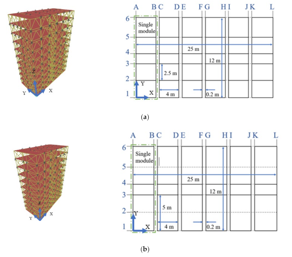
2.1. Design of Modular Buildings

The modular building cases were designed based on the Australian standards AS4100 [41], AS/NZS 1170.2 [42] and AS1170.4 [43]. The buildings were considered to be located in Melbourne, Victoria and classified as importance level 3. The importance level was determined based on the use of the structure, which was considered as a major structure with high consequences of failure according to AS 1170.0 [44]. Further, the building design life was assumed to be 50 years, and the terrain category and wind loading region of the buildings are presumed to be in region A5 and TC4, respectively. The mean regional wind speed was derived as 46 m/s and 37 m/s, respectively, for the ultimate limit state (ULS) and serviceability limit state (SLS). The wind load acting on the case study buildings was calculated using design wind speed, pressure coefficients and tributary area [42,45]. The earthquake on the case study buildings was determined using response spectrum analysis with probability factor (kp = 1.3), hazard factor (Z = 0.09) and sub-soil class Ce, where they were considered to be on shallow soil [43]. The design load (Ed) cases for ULS and SLS were determined using Equations (1)–(6) as given in AS 1170.0 [44]. Equations (1)–(4) were used to derive the design load at ULS, whilst Equations (5) and (6) were used to derive the design load at SLS.
E d = 1.2 G + 1.5 Q
E d = 1.2 G + 0.4 Q + W u
E d = 0.9 G + W u
E d = G + 0.3 Q + E u
E d = G + 0.4 Q + W s
E d = G + 0.4 Q + E s
where, G and Q are dead and live load, respectively. Wu and Ws are the wind load at ULS and SLS, respectively. Eu and Es are the earthquake load at ULS and SLS.
Figure 3 shows the modules used in the case study buildings. The span was doubled in the module used for Building B. The structural element sizes, their capacities and corresponding connection details are listed in Table 1.

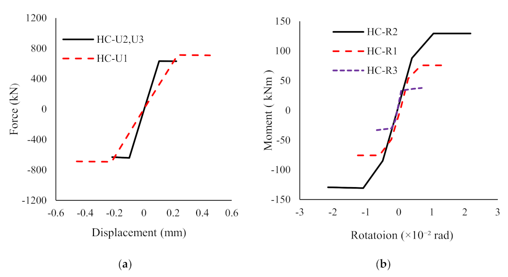
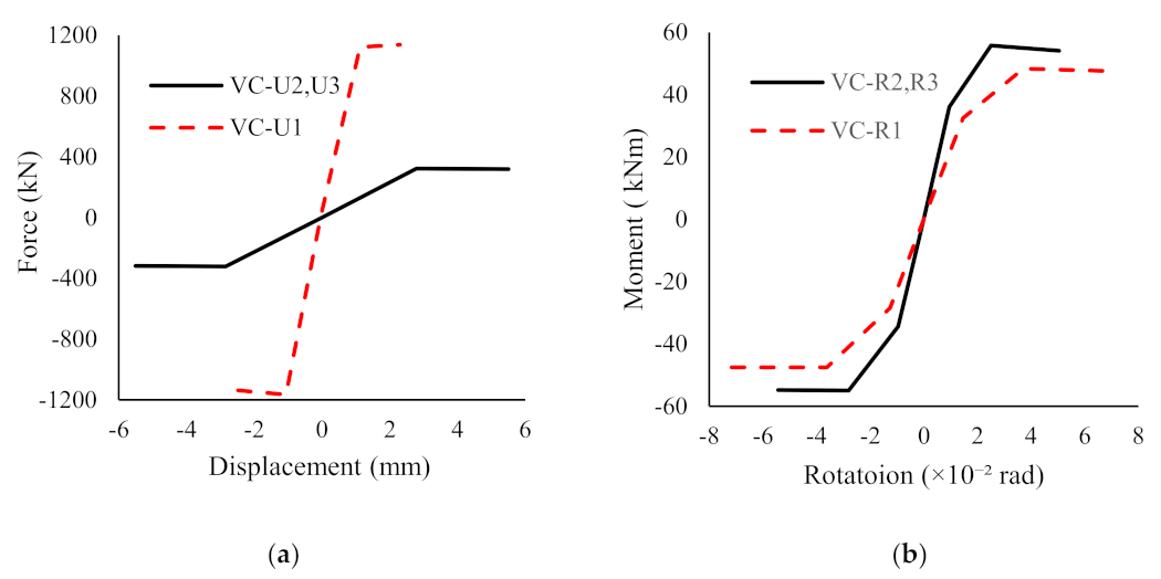
2.2. Numerical Modeling

The modular building cases considered were numerically modelled and analysed through the commercially available finite element (FE) software SAP-2000 [39]. Frame elements were used to model columns, beams and bracings, while shell elements were used to model slabs. The intra-module connections were assumed as rigid connection [46], whilst inter-module connections were replaced with non-linear link elements. The moment curvature and force displacement relationship of the inter module connection were obtained from the research conducted by Lacey et al. [40] and those were used in the FE models. Further, Lacey et al. [40] study states that a one HC should be used per module column, which in reality exists in between the columns of the upper and the lower modules. Thus, in this study a HC was used at the level of ceiling beams to connect two adjacent modules. Similar modelling techniques were used in the previous studies as well [37,47]. Figure 4 and Figure 5 show the translation and rotational behaviour of the VC and HC, respectively. The translation in each direction is indicated by the letter “U” and the rotation is indicated by “R”. A dead load of 0.6 kN/m2 was applied on the floor to represent the self-weight of the floor slab. The super-imposed dead loads acting on the floors and ceilings of the building due to the finishes and services were assumed as 1.0 kN/m2 and 0.5 kN/m2, respectively, in the FE models. Furthermore, a 4.5 kN/m line load was applied on the floor beams to represent the exterior walls and claddings of the building. A live load of 1.5 kN/m2 was applied.

3. Robustness of Modular Buildings

The robustness of the modular building can be assured by event control, and direct and indirect design approaches. In event control, the probability of the risk of collapse is minimised by reducing the probability of accidental events through well-planned design and building layout. In a direct design approach, the structure will be designed to withstand an identified accidental event. The robustness of the structure will be improved by providing a minimal level of strength, continuity and ductility in the indirect design approach [31,48]. An alternate load path method as a direct approach is used to analyse the robustness of the case-study buildings [47]. Thus, column removal scenarios and the related nonlinear static and dynamic analyses were performed on the considered modular buildings under column removal scenarios.
The structural integrity of the buildings was checked by analysing the behaviour of the structure under a loss-of-column scenario, stimulated through three column removal scenarios. GSA guideline [32] was followed when selecting the locations to remove columns to trigger progressive collapses; they were (1) a column at the corner of the building, (2) a column along the edge and (3) an interior column. The same columns (denoted locations) were removed in both building types analysed to compare their load-resisting mechanisms. The columns were labelled to represent the identity of the grid location and the storey level. For example, in the column label B1-2 (see Figure 1), the first letter represents the location on the X axis (grid B), the next number represents the location on the Y axis (grid 1), and the number in the end represents the storey at which the column is removed (level 2). A1-1, B1-1 and B3-1 were the columns removed to stimulate the progressive collapse according to the GSA guideline [32].

3.1. Non-Linear Static Analysis (NLS)

The non-linear static analysis was carried out to investigate the variation of the axial forces of the columns, bending moments in the beams, and displacement at the removed column locations. Non-linear static analysis was carried out by loading the building models after the static removal of the considered column. The design gravity load of α (G +0.25Q) was used as per the GSA guideline [32], where α is the dynamic amplification factor (DAF). GSA [32] suggested using a DAF of 2 to account for the dynamic effect. Thus, this amplified load was assigned to all the bays of the building model. In this study, four DAFs (i.e., 1.0, 1.25, 1.5, and 2.0) were used to estimate the suitable DAF for the considered building cases.

3.2. Non-Linear Dynamic Analysis (NLD)

Following the static analysis, the non-linear dynamic analysis was carried out. The same load combination (G + 0.25Q) with a DAF of 1.0 was used for the analyses. To simulate the column removal, the removed column was replaced with the reactions exerted on that column joint by the column. The reactions were obtained by the analysis of the building before column removal in the considered loading condition under linear static analysis. Then the applied loads were removed through a time history function at a time less than 0.1T (T is the fundamental frequency of the building). The adequate convergence of the results was ensured by using 2000 time-steps of step-size 0.001 s. For Building A, four damping ratios (i.e., 0%, 1%, 2% and 5%) were used to identify the suitable damping ratio for the analyses, since the effect of vertical damping on the progressive collapse needs to be investigated separately between the buildings [49]. The damping ratio, which results in the maximum forces and moments in the members in Building A, was used as the damping ratio of Building B. The damping ratio was kept constant in both the buildings to investigate the effect of changes in the span on the robustness of the structure.
The forces and displacements resulting from the static and dynamic analysis of each column removal scenario were compared with those obtained from ULS combination before the column removal. The scenarios and labels used in this paper are shown in Table 2. Figure 6 shows the removed columns and their labels of the building cases considered. In the label, the first letter denotes the position of the removed column (i.e., C—Corner, E—Edge and I—Interior) and the second letter indicates the type of analysis (i.e., S—Static and D—Dynamic), The numbers at the third position indicate the DAF for static analysis and damping percentage for the dynamic analysis. The final letter indicates the building type (i.e., A—Building A and B—Building B). RA and RB are used to identify Building A and B before the column removal under the ULS loading conditions.

4. Results and Discussion

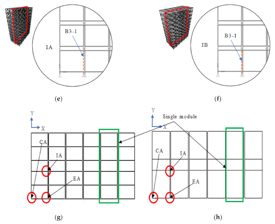
4.1. Effect of Column Removal Location

Initially, the non-linear static and non-linear dynamic analyses were implemented on Building A. Building A remained in the elastic stage during the corner column removal scenario (CA) by distributing the forces among the members. In the other two scenarios (ED and ID), the column with the highest axial force exceeds the capacity of the column, making the structure vulnerable to failure. In the column removal scenarios, members adjacent to the removed column contributed to the load sharing, while other members did not get any significant difference in the forces after the column removal. Figure 7a shows the grid and the percentage increase in the forces in ground floor columns from the dynamic analysis (CD1A), when compared with the accidental load case (1.0G + 0.25Q) in Building A before column removal. The axial forces of the columns A2-1, C1-1 and B1-1 adjacent to the removed column (A1-1) increased by 38%, 24%, and 19%, compared to the accidental load case. In contrast, all other columns experience considerably low increments in the axial forces, in a range of less than 10%.
Figure 7b,c show the percentage increase in the axial forces in ground floor columns in ED1A and ID1A compared with the accidental load case in Building A, before column removal. The columns C1-1 and A1-1 showed about 61% and 12% higher axial force than that from accidental load case (Figure 7b), whilst about 89% and 23% higher forces can be seen in columns C3-1 and B1-1 (Figure 7c). Despite the increase in forces in these columns, B1-1 shows a decrement of 23%. A change of less than 2% was observed in other columns, showing insignificant participation in load sharing. The percentage increment obtained for the columns at the ground floor for the three column removal scenarios are given in Appendix A.
Table 3 presents the vertical displacement at the removed column joint. It can be noted that the displacement at the removed column joint in the CA case was about 146% higher in the NLS with a DAF of 1 (CS1A) compared to that from ULS (RA). Further, this increase in the displacement was 208%, 270% and 393 %, respectively, for the cases of CS1.25A, CS1.5A and CS2A, whilst the displacement at the removed column joint at CA was increased up to 154% in the non-linear dynamic analysis (CD1A). The reason for the difference in the values in the static and dynamic analyses was due to the variations in DAF.
Furthermore, the increase in the displacement in ES1A, ES1.25A, ES1.5A and ES2A was, respectively, 37%, 71%, 105% and 174% higher than the displacement in RA, whilst it was a 39% increment for ED1A case. The increment of 55%, 93%, 132% and 209% can be seen in IS1A, IS1.25A, IS1.5A and IS2A respectively while it is 56% in ID1A. It indicates that the highest increase in the displacement was observed in the corner column removal, and the lowest was observed in the edge column removal. However, the column removal scenarios considered show similar behaviour in both static and dynamic analyses in terms of deflection profiles of the buildings considered.
The demand capacity ratio (DCR) of the elements is derived using Equation (7), and the DCR was used to analyse the robustness of the building. Figure 8, Figure 9 and Figure 10 show the DCR variation of the eight columns in different loading and analyses methods used. Figure 8 compares the axial DCRs of columns between Buildings A and B, when the corner column was removed. The highest DCR recorded for the columns for CD1A and CD1B (column A2-1 and column A3-1) is 0.8 and 0.7. These results indicate that the capacity of the columns does not exceed in the dynamic column removal. Further, Figure 8a indicates that the highest increase in the axial DCR for CA was observed in column A2-1, the column behind the removed column (A1-1). The axial load in column A2-1 for CS1A, CS1.25A, CS1.5A and CS2A was, respectively, 1.0, 1.3, 1.5 and 2.0 times the force in RA. For CD1A, the force was similar to that from both RA and CS1A. When comparing the forces of the columns on the ground floor, column A2-1 shows a 29% higher force than the force in B2-1, which experienced the lowest force among the considered columns. The highest increase in axial DCRs was observed in CB at column A3-1, which was located behind the removed column A1-1 (Figure 8b). The behaviour of the columns in CB was similar to the CA, where the DCR of column A3-1 in CS1B, CS1.25B, CS1.5B and CS2B were, respectively, 0.9, 1.2, 1.4 and 1.9 times the force in RB. Moreover, the force in column A3-1 for CD1A was equal to the RB. The force in column A3-1 was 33% higher than the force in B3-1, which showed the lowest force among the considered columns on the ground floor. The column A1-2, which was above the removed column, experienced a lesser force in all the analyses scenarios when compared with the force in RA. It implies that the loss of support below reduces the axial force in the column and it tends to share the forces with the other adjacent columns.
D e m a n d   C a p a c i t y   R a t i o   D C R = F o r c e s   o r   M o m e n t s   g e n e r a t e d   i n   t h e   e l e m e n t   d u e   t o   l o a d i n g C a p c i t y   o f   t h e   e l e m e n t
The highest increment in the column axial forces in the edge column loss scenario was observed when compared with the corner column loss. The highest DCR was observed in the column C1-1, which was 1.0 for ED1A and 0.8 for ED1B. In the edge column removal, the forces of column C1-1 reached the maximum capacity of the column in Building A, making the building vulnerable to progressive collapse. Figure 9a shows the axial DCRs of the columns with the highest increments in EA. The DCR of C1-1 is 1.2, 1.5, 1.8 and 2.4 higher than the load in RA for ES1A, ES1.25A, ES1.5A and ES2A cases and 1.2 for ED1A. The force in column C1-1 in ED1A was 57% higher than the force in C2-1, which showed the lowest force among the ground floor columns considered. Moreover, C1-1 showed a 46% increment when compared with A1-1, the column showing the second highest force in ED1A analysis. Column C1-1 in EB showed the force increments similar to EA in the cases ES1B, ES1.25B, ES1.5B and ES2B and an increment of 1.3 for ED1A compared to the load in RB (Figure 9b). When considering the increased force in column C1-1 in ED1B, it showed a 65% increment than the force in C3-1, which experienced the lowest force within the considered columns on the ground floor. The increment of C1-1 is 57% relative to column B3-1, experiencing the second highest force in ED1B. The axial DCR variations indicate that the load sharing in the edge column loss is not as effective in the case of corner column loss considering the lesser increment in the forces in other columns.
The variation in the axial DCRs of columns in interior column removal (IA and IB) is given in Figure 10. It shows that the interior column removal scenario gives the highest increment in column axial DCRs and the least efficiency in load sharing among the three scenarios. The highest DCR values observed in column C3-1 for ID1A and ID1B were 1.2 and 1.0, respectively. This indicates that interior column removal is critical for the robustness of the Buildings A and B. Column C3-1 experienced a load that was 1.4, 1.7, 2.1 and 2.8 times higher (Figure 10a) than that in RA of IS1A, IS1.25A, IS1.5A and IS2A, respectively. The load in ID1A was 1.4 times than the load in RA. The increment in the forces in column C3-1 relative to the column, which shows the lowest axial force (A3-1) among the considered ground floor columns, was 108%, while the increment of C3-1 with B4-1 (the column experiences the second highest force) was 82% in ID1A. In IB the load in column C3-1 shows 1.4, 1.7, 2.0 and 2.7 times higher than the load obtained in RB for cases IS1B, IS1.25B, IS1.5B and IS2B, respectively, and 1.4 times the RB in ID1B, which is similar to that of RA (Figure 10b). When considering the changes of axial forces in ground floor columns in ID1B, it was observed that the force in C3-1 was 96% higher than A3-1, the column which showed the lowest axial force among the considered columns. Further, the increment of the forces in C3-1 with the column with second highest axial force (B4-1) was 84%.
Overall, the results of Building A’s analysis indicated that higher forces were generated in the adjacent columns in the interior column removal than in the corner column removal. A similar trend in the results can be seen in Building B, where the IB shows higher forces, when compared with the other two cases, and CB shows the lesser forces. This indicates that for the case-study buildings, interior column removal can be considered as the critical scenario. This result contradicts some research studies reported in the past [40,46]. The research done by Kim et al. [50] concluded that the corner column removal was the most critical scenario. Thai et al. [51] and Alembagheri et al. [46] also suggest that the corner column removal is critical for their case-study modular buildings. The different lateral load supporting systems and the difference in the span lengths leads to the contradictory behavioural patterns of these structures.
Figure 11, Figure 12 and Figure 13 show the DCR of floor and ceiling beams bending moments in Buildings A and B. When considering CA, the moments of FB01 in CS1A, CS1.25A, CS1.5A, CS2A and CD1A are, respectively, 1.0, 1.1, 1.4, 1.9 and 1.0 times the moments of the beam in RA (Figure 11a). In CB the moments in FB 02 in CS1B, CS1.25B, CS1.5B, CS2B and CD1B scenarios are, respectively, 0.6, 0.8, 0.9, 1.2 and 0.6 times the moment of the beam in RB (Figure 11b). Although higher DCRs can be seen in CB, the load increments with respect to RB are comparatively low. This is due to the higher moments due to higher factored loads in ULS loading conditions. The higher DCR shown in CB is due to the lesser capacity in the members used for the ceiling beams.
When considering the edge column removal scenario EA, the moment of FB01 shows the highest moment (Figure 12a). They were found to be 0.9, 1.2, 1.4, 1.9, and 0.9 times higher than the moment of the beam in RA, respectively, in the cases of ES1A, ES1.25A, ES1.5A, ES2A and ED1A. Whilst in the cases ES1B, ES1.25B, ES1.5B, ES2B and ED1B, the moment in FB03 are, respectively, 0.6, 0.8, 0.9, 1.2 and 0.6 times the moment of the beam in RB (Figure 12b).
In the IA scenario, the moments in FB01 in IS1A, IS1.25A, IS1.5A, IS2A and ID1A were, respectively, 0.7, 0.9, 1.1, 1.5, and 0.7 times higher than the moment of the beam in RA (Figure 13a). The moment DCRs experienced by the beams in the IB scenario are shown in Figure 13b. In the cases of IS1B, IS1.25B, IS1.5B, IS2B and ID1B, the moments in FB01 were 0.6, 0.7, 0.9, 1.2 and 0.6 times the moment of the beam in RB, respectively. Similar beam behaviour was observed in all three column removal scenarios in each building. For the beams in Building A, all the column removal analyses generated a maximum DCR of 0.7.
Thus, the results highlight that the beams in Building B experience higher moments due to increased span. A similar behaviour was observed in the research done by Rezvani et al. [52], where the strength of the frame was increased by 1.91 times by reducing the span 0.5 times.

4.2. Effect of Span

The effect of the span on the robustness was checked by comparing the results obtained from Buildings A and B. Partial yielding was observed at the joint regions in Building B for all three column removal scenarios. Thus, there is no collapsing tendency developed since the yielding was less than the ultimate yield stress for the designed loads and the structural performance level of immediate occupancy (IO) for all three column removal scenarios. Building B stayed within the safe limit, with elements not exceeding the member capacity for the dynamic column removal for the column loss scenarios CB and EB. However, for IB, the forces generated in column C3-1 reach the maximum member capacity, where DCR is 1.0 making the interior column removal the critical scenario (Figure 8, Figure 9 and Figure 10).
The development of the plastic hinges (highlighted in pink color circles) in the frames are shown in Figure 14. The greatest number of hinges were formed in corner column removal scenario, which indicates that the number of structural members participating in resisting the progressive collapse in corner column removal is higher than in the other two column removal scenarios. When comparing the increment of the axial forces of columns in Buildings A and B, higher forces were observed in Building B. This was due to the larger span of Building B compared to Building A.
The increment of the span length by 100% (Building B) has resulted in a 21% increase in the axial force in column A2-1 for the static analyses in CB (CS1B, CS1.25B, CS1.5B and CS2B), when compared with the relative analyses in CA (CS1A, CS1.25A, CS1.5A and CS2A). Additionally, an increase of 24% was observed in CD1B relative to CD1A in the considered column A2-1 (Figure 8). When considering the edge column removal (EB) for column C1-1, the increase in the forces for all the static analyses compared to the static analyses in EA is 23%, whilst 25% was observed for ED1B relative to ED1A (Figure 9). Furthermore, in the interior column removal (IB), the force in column C3-1 was observed to be 28% higher in static analyses than in comparative analyses of IA and a 30% increment in ID1B, when compared with ID1A (Figure 10).
The moments generated in the beams in Building B were observed and compared with Building A. Moments of the beams were higher in Building B due to a 100% increase in the span length. When comparing the DCR of beam moments in Building B with A, it was observed that in FB02, the increment due to the static analyses was 58% for all the cases in CB, when compared with comparative static analyses in CA (Figure 11). In FB02, an increment in the moment of 56% was observed for CD1B compared with CD1A (Figure 11). Further, the moment increment in FB03 in EB for all the static analyses relative to the comparative static analyses of EA was 78%. For ED1B, FB03 experienced a moment that was 75% higher than the ED1A (Figure 12). The moment increment of 86% was observed in FB01 for all the static analyses in IB compared to that from IA. Moreover, the increment experienced for FB03 in ID1B was 88% of the DCR of ID1A (Figure 13)

4.3. Estimation of Appropriate DAF

The DAF of 2 was estimated through a structure with a single degree of freedom and no damping. In this case, the elements show elastic behaviour, and the maximum dynamic deflection is twice the static deflection [53]. GSA guideline [32] suggested DAF of 2 to assess the robustness of buildings through the static analysis. This study used the DAF of 2 and found that it overestimates the forces (Figure 8, Figure 9, Figure 10, Figure 11, Figure 12 and Figure 13). Moreover, the forces were within the acceptable range in the dynamic analyses. However, some columns exceeded their capacities during the non-linear static analysis using a DAF of 2.
Furthermore, in the case study buildings with 1% damping, the deflection due to dynamic analysis was within a DAF range of 1.0–1.25 (Table 3). This indicates that DAF between 1.0–1.25 is appropriate to assess the robustness of braced framed modular buildings. This is because the lower DAF values induce non-linear structural behaviour in the building. Therefore, this study recommended verifying the DAF for a building before using the factor in static analyses to assess its robustness.

4.4. Lateral Deformation Due to the Column Loss

The lateral deformation in the building during the dynamic column removal with 1% damping was studied. Figure 15 represents the deformation of the joint near the centre of the roof (G-4 point on the grid) in all three column removal scenario analyses. The results show that the displacement due to corner column removal was significantly higher than in the other cases considered. Higher oscillations were observed in Building B in the range of 1.7–2.7 Hz. Amplitude of the displacement in the Y direction was higher in Building A, while the amplitude for the X direction was higher in Building B.

4.5. Effect of Damping Ratios

Different damping ratios of 0%, 1%, 2% and 5% were used to analyse the effect of vertical damping ratios on the robustness of Building A. The buildings considered collapsed under 0% damping in all three column removal scenarios. The vibrations and energy generated at the column removal could not dissipate under zero-damping, initiating the collapse of the buildings considered.
The load transfer to the adjacent elements after the column removal scenarios was studied. In all three scenarios (CD1A, CD2A and CD5A), there were no significant changes in the forces and moments in the beams whilst increasing the damping ratio. The decrease in the bending moments of the beams was nearly zero when the damping ratio increased from 1% to 5%. The changes in the damping ratio had a negligible effect on the axial forces of columns, where the highest reduction was 0.22% for all the considered columns in the three removal scenarios. The changes in column axial forces and beams for the corner column removal are presented in Table 4. When comparing all three column loss scenarios, the changes in the damping ratio have a higher impact on the robustness when the corner column loss (CA) and the least impact due to interior column loss (IA).
The variations of damping ratio with the vertical displacement at the joint of the removed column and lateral displacement near the centre at the roof of the building (G-4 on the grid) are presented in Figure 16. It can be noted that the variation of damping of the building significantly influences the stability of the structure. The highest stability effect was induced through damping occurred when the corner column was removed, whilst a lesser impact was observed in the other two scenarios (edge and interior column removal). Therefore, the data of corner column removal were used to present the behaviour of all three scenarios. Figure 16 shows the displacement of the considered locations of CA in dynamic analyses with different damping ratios. It was identified that the displacement due to the 1% damping ratio was higher than in the other cases, although the increment is not significant. Similar behaviour was observed in the research done by Kiakojouri et al. [54].
Considering the variation of forces and the displacement with the increase in the damping ratio for a design of a building, it will be beneficial to use higher damping to reduce the forces on the members and the displacements. For the purpose of analysis, 1% of damping was used to check the stability of the building, which resulted in higher forces and displacement. Yu et al. [55] mentioned in their study that the structures with 0% damping are more conservative against the progressive collapse. This is because higher member forces are generated in the structure with no damping than in the structure with damping. Therefore, the structure needs to be assessed with 0% damping as it enables conservative design.

5. Conclusions

This paper presents the outcome of case study analyses carried out to evaluate the load-resisting mechanisms during different column removal scenarios to comprehend the robustness of braced modular buildings. Two types of modules with different span lengths and three different column removal scenarios were studied for a typical ten-storey modular building system. The load-resisting mechanism of the building cases were analysed, and their progressive collapse modes were assessed through non-linear static and non-linear dynamic analysis using SAP2000 [39]. Based on the outcomes of the analyses carried out, following conclusions are drawn.
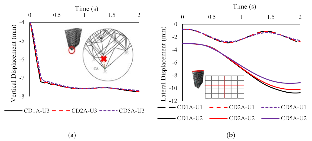
  • The analyses revealed that 1% damping can be considered to assess the robustness of typical modular building types. Although a significant change in the element forces and displacements could not be observed, the highest forces and displacements were recorded in the models with 1% damping. Considering the three column loss scenarios analysed, the effect of the changes in damping ratio for building A was significant in the corner column loss scenario.
  • It was observed from the analyses that the corner column removal scenario does not significantly reduce the robustness compared to the other two column removal scenarios (edge and interior column removal). It was further discovered that the corner column removal scenario has the ability of sharing the forces to the adjacent elements than the other two scenarios. The formation of several hinges in the frame indicates the participation of higher number of members in load sharing mechanism of the modular building systems considered.
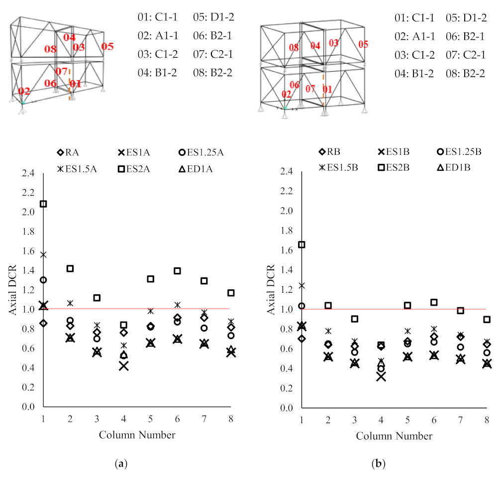
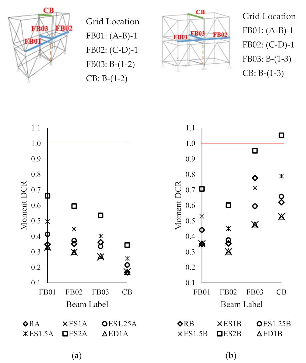
  • When the span of the module was doubled, the column loss in the corner showed the highest increment in axial forces (i.e., axial demand capacity ratios (DCR) of the columns). The increment in axial DCRs of edge, interior, and corner column losses are 23%, 24% and 30%, respectively. The increments of the bending capacity ratios of the beams adjacent to the collapsed columns for the aforementioned those cases were 56%, 75% and 88% respectively, and significantly affected the performance of the building under the interior column removal scenario than in the other two cases.
  • The results from the nonlinear static analysis and nonlinear dynamic analysis indicate that the use of DAF of 2 for modular buildings was an over-estimation. When considering the axial forces in columns and the moments in the beams, a DAF value of 1.25 can be used, since the values obtained the dynamic analyses are in the range of 1.0 to 1.25. This may not be valid for all the layouts and heights. Therefore, further analyses with different parameters such as material properties and sectional details are required.
It can be said that the analyses and results presented in this study can be useful to extend the understanding of the robustness of modular building system. Nonetheless, this study is only limited to a ten-storey building with a fixed height and plan area with a chosen inter-module connection type and lateral load-resisting system. The column removal was limited only to the ground floor. Therefore, further studies should be considered with different heights and layouts, with column removal scenarios at different levels of the building. Also, different types of inter-module connections and lateral load-resisting systems can be adopted to assess the robustness of the modular building systems. Furthermore, the behaviour of buildings with several lines of modules connected instead of one can be investigated in the future to develop appropriate design guidelines to prevent progressive collapses of modular building systems.

Author Contributions

Conceptualization, S.N. and T.P.; methodology, S.N. and T.P.; software, T.M.; validation, T.M., S.N. and H.-G.H.D. formal analysis, T.M. and T.P.; investigation, T.M. and T.P.; resources, T.P., H.-G.H.D. and G.Z.; data curation, S.N., J.T., T.P., H.-G.H.D. and K.D.T.; writing—original draft preparation, T.M. and S.N.; writing—review and editing, S.N., J.T., T.P., H.-G.H.D., K.D.T. and G.Z.; visualization, T.M. and J.T.; supervision, S.N., T.P., H.-G.H.D. and G.Z.; project administration, S.N.; funding acquisition, S.N. All authors have read and agreed to the published version of the manuscript.

Funding

This work is funded by Ronnie & Koh Consultants Pte Ltd., Singapore and Skyline Consulting Engineers, Sri Lanka.

Institutional Review Board Statement

Not applicable.

Informed Consent Statement

Not applicable.

Data Availability Statement

Not applicable.

Acknowledgments

Authors acknowledge RMIT University, University of Moratuwa, South Eastern University of Sri Lanka and City, University of London for their supports in terms of technical, financial and other research facilities.

Conflicts of Interest

The authors declare there are no conflict of interest in this research.

Appendix A

Table A1. The percentage of change in force in ground floor’s columns in CD1A by the column location.
Grid YGrid X (%)
ABCDEFGHIJKL
1-25328843211−1−5
241−2510201−11−1−2
310−23101−11−11−1−3
48−110−1421−11−1−2
53101−10−11−11−1−2
6−13−10−2−2−4−1−3−3−5−5
Table A2. The percentage of change in force in ground floor’s columns in ED1A by the column location.
Grid YGrid X (%)
ABCDEFGHIJKL
112-6187221010−1
245−3001000000
323−300000000−1
412−2001000000
5100000000000
62−200000000−1−2
Table A3. The percentage of change in force in ground floor’s columns in ID1A by the column location.
Grid YGrid X (%)
ABCDEFGHIJKL
1−223−13−1−20−10−100−1
2−1200−10000000
30-89010000000
40410−10−10000−1
501−10−10000000
602−10−1−100000−1

Nomenclature

Symbols
ABuilding A
BBuilding B
CCorner column loss
DDynamic analysis
Ce Sub soil class (Shallow soil)
EEdge column loss
EdDesign load
GDead load
IInterior column loss
kpProbability factor
QLive load
RRotation
RABuilding A before column removal under ULS loading condition
RBBuilding B before column removal under ULS loading condition
SStatic analysis
TFundamental frequency of the building
UTranslation
WWind Load
Subscripts
sLoad at serviceability limit state
uLoad at ultimate limit state
Abbreviations
DAFDynamic Amplification Factor
DCRDemand Capacity Ratio
FEFinite Element
HCHorizontal Connection
IOImmediate Occupancy
NLDNon-linear dynamic analysis
NLSNon-linear static analysis
SLSServiceability Limit State
ULSUltimate Limit State
VCVertical Connection

References

  1. Deng, E.-F.; Zong, L.; Ding, Y.; Zhang, Z.; Zhang, J.-F.; Shi, F.-W.; Cai, L.-M.; Gao, S.-C. Seismic performance of mid-to-high rise modular steel construction-A critical review. Thin-Walled Struct. 2020, 155, 106924. [Google Scholar] [CrossRef]
  2. Ferdous, W.; Bai, Y.; Ngo, T.D.; Manalo, A.; Mendis, P. New advancements, challenges and opportunities of multi-storey modular buildings—A state-of-the-art review. Eng. Struct. 2019, 183, 883–893. [Google Scholar] [CrossRef]
  3. Ye, Z.; Giriunas, K.; Sezen, H.; Wu, G.; Feng, D.C. State-of-the-art review and investigation of structural stability in multi-story modular buildings. J. Build. Eng. 2021, 33, 101844. [Google Scholar] [CrossRef]
  4. Kamali, M.; Hewage, K. Life cycle performance of modular buildings: A critical review. Renew. Sustain. Energy Rev. 2016, 62, 1171–1183. [Google Scholar] [CrossRef]
  5. Minunno, R.; O’Grady, T.; Morrison, G.M.; Gruner, R.L. Exploring environmental benefits of reuse and recycle practices: A circular economy case study of a modular building. Resour. Conserv. Recycl. 2020, 160, 104855. [Google Scholar] [CrossRef]
  6. Kamali, M.; Hewage, K.; Sadiq, R. Economic sustainability benchmarking of modular homes: A life cycle thinking approach. J. Clean. Prod. 2022, 348, 131290. [Google Scholar] [CrossRef]
  7. Razkenari, M.; Fenner, A.; Shojaei, A.; Hakim, H.; Kibert, C. Perceptions of offsite construction in the United States: An investigation of current practices. J. Build. Eng. 2020, 29, 101138. [Google Scholar] [CrossRef]
  8. Chen, Z.; Popovski, M.; Ni, C. A novel floor-isolated re-centering system for prefabricated modular mass timber construction—Concept development and preliminary evaluation. Eng. Struct. 2020, 222, 111168. [Google Scholar] [CrossRef]
  9. Liew, J.Y.R.; Chua, Y.S.; Dai, Z. Steel concrete composite systems for modular construction of high-rise buildings. Structures 2019, 21, 135–149. [Google Scholar] [CrossRef]
  10. Loss, C.; Davison, B. Innovative composite steel-timber floors with prefabricated modular components. Eng. Struct. 2017, 132, 695–713. [Google Scholar] [CrossRef]
  11. Wang, Z.; Pan, W.; Zhang, Z. High-rise modular buildings with innovative precast concrete shear walls as a lateral force resisting system. Structures 2020, 26, 39–53. [Google Scholar] [CrossRef]
  12. Navaratnam, S.; Small, D.W.; Gatheeshgar, P.; Poologanathan, K.; Thamboo, J.; Higgins, C.; Mendis, P. Development of cross laminated timber-cold-formed steel composite beam for floor system to sustainable modular building construction. Structures 2021, 32, 681–690. [Google Scholar] [CrossRef]
  13. Thamboo, J.; Zahra, T.; Navaratnam, S.; Asad, M.; Poologanathan, K. Prospects of Developing Prefabricated Masonry Walling Systems in Australia. Buildings 2021, 11, 294. [Google Scholar] [CrossRef]
  14. Hyun, H.; Lee, Y.M.; Kim, H.G.; Kim, J.S. Framework for long-term public housing supply plan focusing on small-scale offsite construction in Seoul. Sustainability 2021, 13, 5361. [Google Scholar] [CrossRef]
  15. Musa, M.F.; Yusof, M.R.; Mohammad, M.F.; Samsudin, N.S. Towards the adoption of modular construction and prefabrication in the construction environment: A case study in Malaysia. ARPN J. Eng. Appl. Sci. 2016, 11, 8122–8131. [Google Scholar]
  16. Navaratnam, S.; Satheeskumar, A.; Zhang, G.; Nguyen, K.; Venkatesan, S.; Poologanathan, K. The challenges confronting the growth of sustainable prefabricated building construction in Australia: Construction industry views. J. Build. Eng. 2022, 48, 103935. [Google Scholar] [CrossRef]
  17. Gao, S.; Jin, R.; Lu, W. Design for manufacture and assembly in construction: A review. Build. Res. Inf. 2020, 48, 538–550. [Google Scholar] [CrossRef]
  18. Thai, H.-T.; Ngo, T.; Uy, B. A review on modular construction for high-rise buildings. Structures 2020, 28, 1265–1290. [Google Scholar] [CrossRef]
  19. Gatheeshgar, P.; Parker, S.; Askew, K.; Poologanathan, K.; Navaratnam, S.; McIntosh, A.; Small, D.W. Flexural behaviour and design of modular construction optimised beams. Structures 2021, 32, 1048–1068. [Google Scholar] [CrossRef]
  20. Gatheeshgar, P.; Poologanathan, K.; Thamboo, J.; Roy, K.; Rossi, B.; Molkens, T.; Perera, D.; Navaratnam, S. On the fire behaviour of modular floors designed with optimised cold-formed steel joists. Structures 2021, 30, 1071–1085. [Google Scholar] [CrossRef]
  21. Liu, X.; Zhou, X.; Zhang, A.; Tian, C.; Zhang, X.; Tan, Y. Design and compilation of specifications for a modular-prefabricated high-rise steel frame structure with diagonal braces. Part I: Integral structural design. Struct. Des. Tall Spec. Build. 2018, 27, e1415. [Google Scholar] [CrossRef]
  22. Srisangeerthanan, S.; Hashemi, M.J.; Rajeev, P.; Gad, E.; Fernando, S. Numerical study on the effects of diaphragm stiffness and strength on the seismic response of multi-story modular buildings. Eng. Struct. 2018, 163, 25–37. [Google Scholar] [CrossRef]
  23. Sultana, P.; Youssef, M.A. Seismic Performance of Modular Steel-Braced Frames Utilizing Superelastic Shape Memory Alloy Bolts in the Vertical Module Connections. J. Earthq. Eng. 2020, 24, 628–652. [Google Scholar] [CrossRef]
  24. Dan-Adrian, C.; Tsavdaridis, K.D. A comprehensive review and classification of inter-module connections for hot-rolled steel modular building systems. J. Build. Eng. 2022, 50, 104006. [Google Scholar]
  25. Lacey, A.W.; Chen, W.; Hao, H.; Bi, K. Review of bolted inter-module connections in modular steel buildings. J. Build. Eng. 2019, 23, 207–219. [Google Scholar] [CrossRef]
  26. Lacey, A.W.; Chen, W.; Hao, H.; Bi, K. Structural response of modular buildings—An overview. J. Build. Eng. 2018, 16, 45–56. [Google Scholar] [CrossRef]
  27. Lawson, M.; Ogden, R.; Goodier, C. Design in Modular Construction; CRC: Boca Raton, FL, USA, 2014. [Google Scholar]
  28. Murray-Parkes, J.B.Y.; Styles, A.; Wang, A. Handbook for the Design of Modular Structures; Construction Codes Board: Melbourne, Australia, 2017.
  29. Diab, M.e.; Desprez, C.; Orcesi, A.; Bleyer, J. Structural robustness quantification through the characterization of disproportionate collapse compared to the initial local failure. Eng. Struct. 2022, 255, 113869. [Google Scholar] [CrossRef]
  30. Izzuddin, B.A. Rational Robustness Design of Multistory Building Structures. J. Struct. Eng. 2022, 148, 04021279. [Google Scholar] [CrossRef]
  31. General Services Administration. Alternate Path Analysis and Design Guidelines for Progressive Collapse Resistance; revision 1; General Services Administration: Washington, DC, USA, 2016.
  32. General Services Administration. Progressive Collapse Analysis and Design Guidelines for New Federal Office Buildings and Major Modernization Projects; General Services Administration: Washington, DC, USA, 2003.
  33. Ghobadi, M.S.; Yavari, H. Progressive collapse vulnerability assessment of irregular voided buildings located in Seismic-Prone areas. Structures 2020, 25, 785–797. [Google Scholar] [CrossRef]
  34. Kokot, S. Response spectrum of a reinforced concrete frame structure under various column removal scenarios. J. Build. Eng. 2022, 49, 103992. [Google Scholar] [CrossRef]
  35. Nair, R. Progressive collapse basics. J. Modern Steel Constr. 2004, 44, 37–42. [Google Scholar]
  36. Jeyarajan, S. Robustness Analysis and Design of Steel Concrete Composite Buildings. In Proceedings of the Twenty-Sixth KKHTCNN Symposium on Civil Engineering, Singapore, 18–20 November 2013. [Google Scholar]
  37. He, X.H.C.; Chan, T.M.; Chung, K.F. Effect of inter-module connections on progressive collapse behaviour of MiC structures. J. Constr. Steel Res. 2021, 185, 106823. [Google Scholar] [CrossRef]
  38. Peng, J.; Hou, C.; Shen, L. Progressive collapse analysis of corner-supported composite modular buildings. J. Build. Eng. 2022, 48, 103977. [Google Scholar] [CrossRef]
  39. SAP2000, Integrated Software for Structural Analysis and Design; Computers and Structures, Inc.: Berkeley, CA, USA, 2017.
  40. Lacey, A.W.; Chen, W.; Hao, H.; Bi, K. Effect of inter-module connection stiffness on structural response of a modular steel building subjected to wind and earthquake load. Eng. Struct. 2020, 213, 110628. [Google Scholar] [CrossRef]
  41. AS 4100A; Standards, Steel Structures (Reconfirmed 2016 Incorporating Amendment No. 1). Standards Australia: Sydney, Australia, 2016.
  42. AS/NZS 1170.2:2011; Australian/New Zealand Standard for Structural Design Actions, Part 2: Wind Actions. Standards Australia: Sydney, Australia, 2011.
  43. AS 1170.4-2007; Structural Design Actions-Part 4: Earthquake Actions in Australia, BD-006 (General Design Requirements and Loading on Structures). Standards Australia: Sydney, Australia, 2007.
  44. AS/NZS 1170.0; Structural design actions—Part 0: General principals, Sydney, 2002. Standards Australia, and New Zealand: Sidney, Australia.
  45. Satheeskumar, N.; Henderson, D.J.; Ginger, J.D.; Wang, C.H. Finite element modelling of the structural response of roof to wall framing connections in timber-framed houses. Eng Struct. 2017, 134, 25–36. [Google Scholar] [CrossRef]
  46. Alembagheri, M.; Sharafi, P.; Tao, Z.; Hajirezaei, R.; Kildashti, K. Robustness of multistory corner-supported modular steel frames against progressive collapse. Struct. Des. Tall Spec. Build. 2021, 30, e1896. [Google Scholar] [CrossRef]
  47. Chua, Y.S.; Pang, S.D.; Liew, J.Y.R.; Dai, Z. Robustness of inter-module connections and steel modular buildings under column loss scenarios. J. Build. Eng. 2022, 47, 103888. [Google Scholar] [CrossRef]
  48. Unified Facilities Criteria, Design of Buildings to Resist Progressive Collapse; U.S. Army Corps of Engineers: Washington, DC, USA, 2009.
  49. Yu, J.; Yin, C. Effect of damping on progressive collapse performance of structures. In Mechanics of Structures and Materials, Advancement and Challenges; CRC Press: Boca Raton, FL, USA, 2016; pp. 715–720. [Google Scholar]
  50. Kim, J.; Kim, T. Assessment of progressive collapse-resisting capacity of steel moment frames. J. Constr. Steel Res. 2009, 65, 169–179. [Google Scholar] [CrossRef]
  51. Thai, H.T.; Ho, Q.V.; Li, W.; Ngo, T. Progressive collapse and robustness of modular high-rise buildings. Struct. Infrastruct. Eng. 2021, 104, 643–656. [Google Scholar] [CrossRef]
  52. Rezvani, F.H.; Yousefi, A.M.; Ronagh, H.R. Effect of span length on progressive collapse behaviour of steel moment resisting frames. Structures 2015, 3, 81–89. [Google Scholar] [CrossRef]
  53. Russell, J.M.; Owen, J.S.; Hajirasouliha, I. Dynamic column loss analysis of reinforced concrete flat slabs. Eng. Struct. 2019, 198, 109453. [Google Scholar] [CrossRef]
  54. Kiakojouri, F.; Sheidaii, M.R. Effects of finite element modeling and analysis techniques on response of steel moment-resisting frame in dynamic column removal scenarios. Asian J. Civ. Eng. 2018, 19, 295–307. [Google Scholar] [CrossRef]
  55. Yu, J.; Yin, C.; Guo, Y. Nonlinear SDOF model for progressive collapse responses of structures with consideration of viscous damping. J. Eng. Mech. 2017, 143, 04017108. [Google Scholar] [CrossRef]
Figure 1. 3 D and plan views of case study buildings: (a) Building A; and (b) Building B.
Buildings 12 01289 g001
Figure 2. Inter module connections used in the building: (a) arrangement of connections in the building; (b) vertical connection [40]; and (c) horizontal connection [40].
Buildings 12 01289 g002
Figure 3. Modules used in the case study building: (a) Building A; and (b) Building B.
Buildings 12 01289 g003
Figure 4. Behaviour of horizontal connection: (HC) (a) Translation; (b) Rotation.
Buildings 12 01289 g004
Figure 5. Behaviour of vertical connection (VC): (a) Translation; (b) Rotation.
Buildings 12 01289 g005
Figure 6. Column removal scenarios of Building A: (a) CA; (b) EA; (c) IA; and Building B (d) CB; (e) EB; (f) IB; and plan view of (g) Building A; (h) Building B with the removed column locations.
Buildings 12 01289 g006aBuildings 12 01289 g006b
Figure 7. Percentage of change in force in ground floor’s columns in: (a) CD1A; (b) ED1A; and (c) ID1A with Accidental Load case in Building A without column removal.
Buildings 12 01289 g007
Figure 8. Column axial capacity ratios for corner column removal: (a) Building A; and (b) Building B.
Buildings 12 01289 g008
Figure 9. Column axial capacity ratios for edge column removal: (a) Building A; and (b) Building B.
Buildings 12 01289 g009
Figure 10. Column axial capacity ratios for interior column removal: (a) Building A; and (b) Building B.
Buildings 12 01289 g010
Figure 11. Beam moment capacity ratios for corner column removal: (a) Building A; and (b) Building B.
Buildings 12 01289 g011
Figure 12. Beam moment capacity ratios for edge column removal: (a) Building A; and (b) Building B.
Buildings 12 01289 g012
Figure 13. Beam moment capacity ratios for interior column removal: (a) Building A; and (b) Building B.
Buildings 12 01289 g013
Figure 14. Formation of hinges in Building B in the dynamic analysis: (a) Corner column removal (CB); (b) Edge column removal (EB); and (c) Interior column removal (IB).
Buildings 12 01289 g014
Figure 15. The displacement at the top of the buildings in dynamic column removal of 1% damping: (a) Building A; and (b) Building B.
Buildings 12 01289 g015
Figure 16. Effect of change of damping ratio on CA: (a) Vertical displacement at removed column joint; and (b) Lateral displacement at roof of the building.
Buildings 12 01289 g016
Table 1. The size and element types used in the case study modular buildings.
DetailsBuilding ABuilding B
Floor area per one accommodation (m2)18.718.7
Modular size (m)4 × 12 × 34 × 12 × 3
Column size (mm)/(Member Capacity (kN))SHS 150 × 150 × 8/(680)SHS 150 × 150 × 8/(1050)
Floor beam size (mm)/(Member Capacity (kNm))SHS 120 × 80 × 5/(20.5)SHS 150 × 100 × 5/(33.5)
Ceiling beam size (mm)/(Member Capacity (kNm))SHS 70 × 70 × 5/(8.5)SHS 70 × 70 × 5/(8.5)
Bracing size (mm)/(Member capacity (kN))SHS 80 × 80 × 6.3/(140)SHS 80 × 80 × 6.3/(140)
Floor20 mm thick cement board with floor purlins at 400 mm centre to centre20 mm thick cement board with floor purlins at 400 mm centre to centre
CeilingGypsum boardGypsum board
Inter module connectionFigures 4 and 5 [40]Figures 4 and 5 [40]
FoundationShallow foundationShallow foundation
Table 2. Analysis scenarios considered for the case study buildings.
Building A (A)Building B (B)
Corner Column Loss (CA)Edge
Column Loss (EA)
Interior Column Loss (IA)Corner Column Loss (CB)Edge
Column Loss (EB)
Interior Column Loss (IB)
Reference (1.2G + 1.5Q)RARARARBRBRB
Static Analysis
(S)
DAF = 1CS1AES1AIS1ACS1BES1BIS1B
DAF = 1.25CS1.25AES1.25AIS1.25ACS1.25BES1.25BIS1.25B
DAF = 1.5CS1.5AES1.5AIS1.5ACS1.5BES1.5BIS1.5B
DAF = 2CS2AES2AIS2ACS2BES2BIS2B
Dynamic Analysis (D)0%CD0AED0AID0A---
1%CD1AED1AID1ACD1BED1BID1B
2%CD2AED2AID2A---
5%CD5AED5AID5A---
Table 3. Vertical displacement at the removed column joint in each column removal scenarios in Building A.
ColumnRANLSNLD
DAF = 1DAF = 1.25DAF = 1.5DAF = 2
A1-1−3.05−7.51 (CS1A)−9.4 (CS1.25A)−11.27 (CS1.5A)−15.03 (CS2A)−7.75 (CD1A)
B1-1−3.07−4.2 (ES1A)−5.25 (ES1.25A)−6.3 (ES1.5A)−8.4 (ES2A)−4.28 (ED1A)
B3-1−2.14−3.31 (IS1A)−4.14 (IS1.25A)−4.97 (IS1.5A)−6.62 (IS2A)−3.33 (ID1A)
Table 4. The variation of member forces due to different damping ratios.
Axial Forces of Columns
(kN)
Moments in Beams
(kNm)
B1-1C1-1C1-2B1-2FB01FB02
Dynamic Analysis (D)CD1A−523.38−556.87−457.76−447.726.896.38
CD2A−522.38−555.84−457.02−446.876.886.36
CD5A−520.64−553.98−455.81−445.326.876.34
Publisher’s Note: MDPI stays neutral with regard to jurisdictional claims in published maps and institutional affiliations.

