Article

Effect of Welding Separation Characteristics on the Cyclic Behavior of Steel Plate Shear Walls

1
Department of Civil and Environmental Engineering, University of Missouri, Columbia, MO 65211, USA
2
Department of Structural Engineering, Zagazig University, Zagazig 44519, Egypt
*
Author to whom correspondence should be addressed.
Buildings 2022, 12(7), 879; https://doi.org/10.3390/buildings12070879
Submission received: 20 May 2022 / Revised: 12 June 2022 / Accepted: 16 June 2022 / Published: 22 June 2022
(This article belongs to the Special Issue Seismic Design of Building Structures)

Abstract

:
Currently, the steel plate shear wall (SPSW) is commonly used in high-rise steel buildings as a lateral load-resisting system due to its several advantages such as its lightweight and high ductility and strength. The SPSW consists of two main parts, i.e., the boundary frame and infill plate, which are connected by welding. The objective of this work is to study the effect of the infill plate weld separation on the seismic behavior of the SPSWs. A numerical method was proposed to have a comprehensive comparison of seismic behaviors of different separation characteristics. The model was validated by using previously published experimental works. Key parameters, such as load-carrying capacity, stiffness, and energy-dissipation capacity, were discussed extensively. The unstiffened SPSW (USPSW) system is more sensitive to the plate–beam separation than the plate–column one, especially the corner plate–beam separation. When plate–column welding separation occurs, the initial stiffness and the energy dissipation capacity are reduced by approximately 21% and 14%, respectively; however, the reductions are 36% and 20.5% in the case of beam welding separation.

1. Introduction

The steel plate shear wall consists of a boundary frame, fish plate, and infill panel, as shown in Figure 1a. The steel plate shear wall is commonly used in high-rise steel buildings as a lateral load-resisting system. Steel plate shear walls (SPSWs) are preferred by designers due to their many advantages, such as being lightweight, easily constructed, and have reduced structure reactions. The SPSW is a lateral load-resisting system with high lateral strength, initial stiffness (K1), and load-carrying capacity [1,2]. Several works have been conducted on the SPSW system to assess its seismic behavior by studying the load-carrying capacity and energy dissipation [3,4,5,6,7,8,9,10,11,12,13,14]. It was found that thin unstiffened SPSWs (USPSWs) can achieve high post-buckling strength and good seismic behavior, which can be attributed to tension field action. Using thin USPSWs instead of thick USPSWs produces early tension field action that can dissipate more energy by acting as a plastic hinge [4]. Since, usually, the selected steel plate’s thickness is low, the tension stresses upon the steel plate are very high, which makes the occurrence of cracks highly probable. In the multitude of experimental tests, cracks and their propagation on SPSWs have been observed. In the majority of tests, cracks accidentally occurred due to the welding nature, which impacted the test outcome. Although experimental works reported a high crack propagation probability in SPSWs, this phenomenon has not yet been completely studied. In other words, cracks have a significant effect on the seismic behavior of SPSWs, although no significant studies have been conducted thus far.
In this section, a literature review related to cracked SPSWs is summarized. An investigation on the impact of cracks on the seismic behavior of USPSWs was performed by Broujerdian et al. [15]. It was found that crack propagation had a significant effect on the seismic behavior of USPSWs in the elastic and inelastic regions that cannot be overlooked. However, this research was only restricted to examining the impact of plate cracks on USPSWs. The behavior of USPSWs under dynamic and static loading was studied by Qu et al. [16]. It was found that SPSWs under static loading showed more initial stiffness than dynamic ones; however, unexpected crack growth on the first floor occurred in the full-scale test. The ability of USPSWs in seismic retrofitting was studied experimentally [17]. It was found that, in one of the test samples, low ductility was observed due to crack growth in the steel plate. The research did not aim to assess cracking and its growth, whereas the results showed that crack growth caused a severe reduction in ductility. An experimental study on diagonally stiffened SPSWs (SSPSW) with central perforation was conducted [18]. Although the authors did not aim to assess the cracks and their propagation, the cracks affected the test results.
Other works reported that the impact of a crack on the out-of-plane buckling behavior and the panel’s load-carrying capacity must be considered carefully in the design process [19,20,21,22,23,24]. The behavior of cracked plates under the influence of tensile and compressive axial loads was studied [25]. It was found that the prebuckling load-carrying capacity was reduced by increasing the crack length.
The effect of the crack length, boundary conditions, and biaxial loading on the buckling and postbuckling behavior of thin plates was studied using a numerical simulation [26,27]. It was found that the postbuckling causes excessive deformations, which lead to a tension stress concentration on the tip of the crack that causes the crack to initiate and propagate. In line with that research, limited studies have been conducted to study the effect of cracks on thin plates under pure shear [28,29], axial compression [30,31,32], and axial tension [33,34]. It was found that the initial crack length had a significant effect on crack propagation. The effect of cracks on SPSWs strengthened with diagonal stiffeners was studied [35,36]. It was found that cracks propagated in the nonlinear zone, so it was not effective on the elastic behavior of diagonally stiffened SPSWs. The effect of cracks was also presented using mathematical equations to estimate the load–displacement curves. These curves were in agreement with the finite element results, especially for thicker wall stiffeners. The results showed that the cracked wall with thicker stiffeners had better performance than one with thinner stiffeners. However, diagonal stiffeners had a more significant effect in reducing the undesirable influence of crack propagation on the load-carrying capacity of the walls. For the diagonal stiffeners, increasing the thickness enhanced the load-carrying capacity by 44% for uncracked walls, and 34% for cracked walls. On the other hand, thicker stiffeners improved the wall energy absorption by 53%, and 57% for uncracked and cracked walls, respectively.
Finally, the infill plate interconnection effects on the structural behavior of steel plate shear walls were numerically studied [37]. The behavior of the partially connected plates with different interconnection types was compared to the fully connected infill plate. It was found that a system with an 80% connection between the infill plates and boundary elements had a lower load-carrying capacity, stiffness, ductility, and energy-dissipation capacity than a fully connected system by approximately 1.1, 3.5, 2.4, and 1.4%, respectively.
It could be observed from the survey that the previous research was mostly limited to cracked SPSWs, in which there was welding between the infill pate and the boundary frame. Although cracked walls were studied in different works, most of them focused on cracks that occurred in the plates. None of them focused on the cracks that occurred in the welding between the plate and the boundary frame, which occur due to aging and construction error.
Therefore, the purpose of this paper is to perform a comparative study to investigate the behaviors of different welding separation characteristics. These separations can happen due to aging, cyclic wind loads, or fabrication deficiency, and their effect on hysteretic and other behaviors is investigated. To execute this, a numerical model was built by using ABAQUS finite element code and validating it using published results. The model was then used to study the aforementioned parameters.

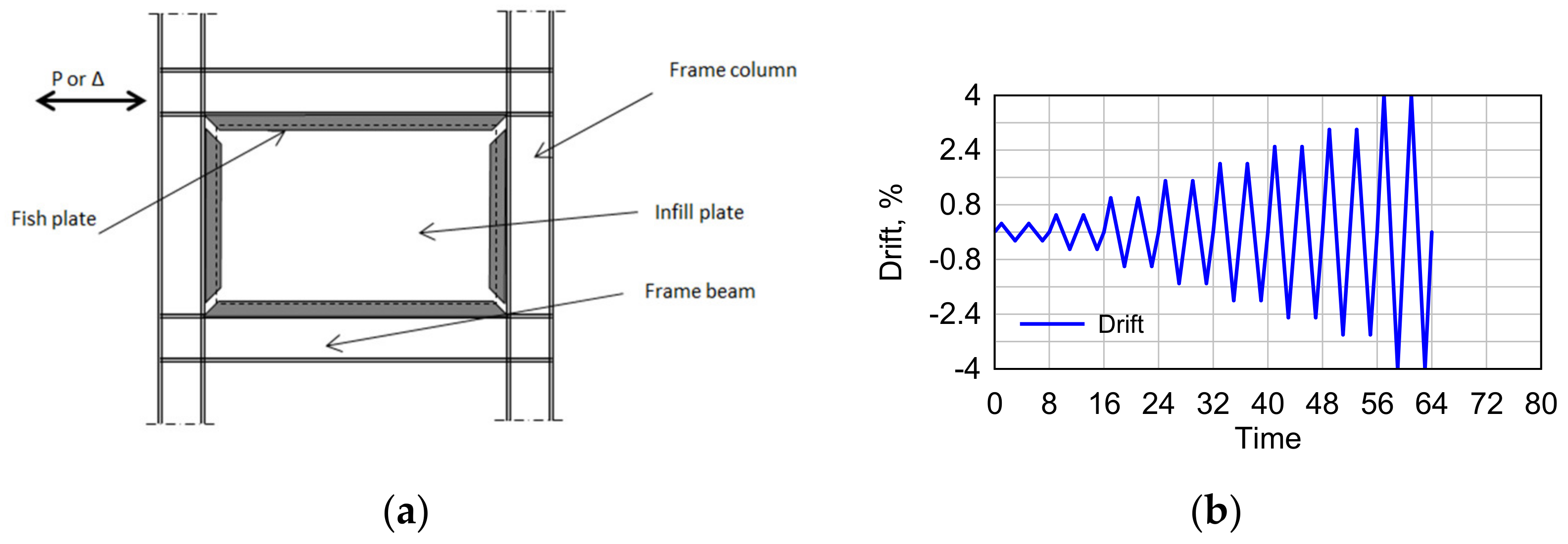
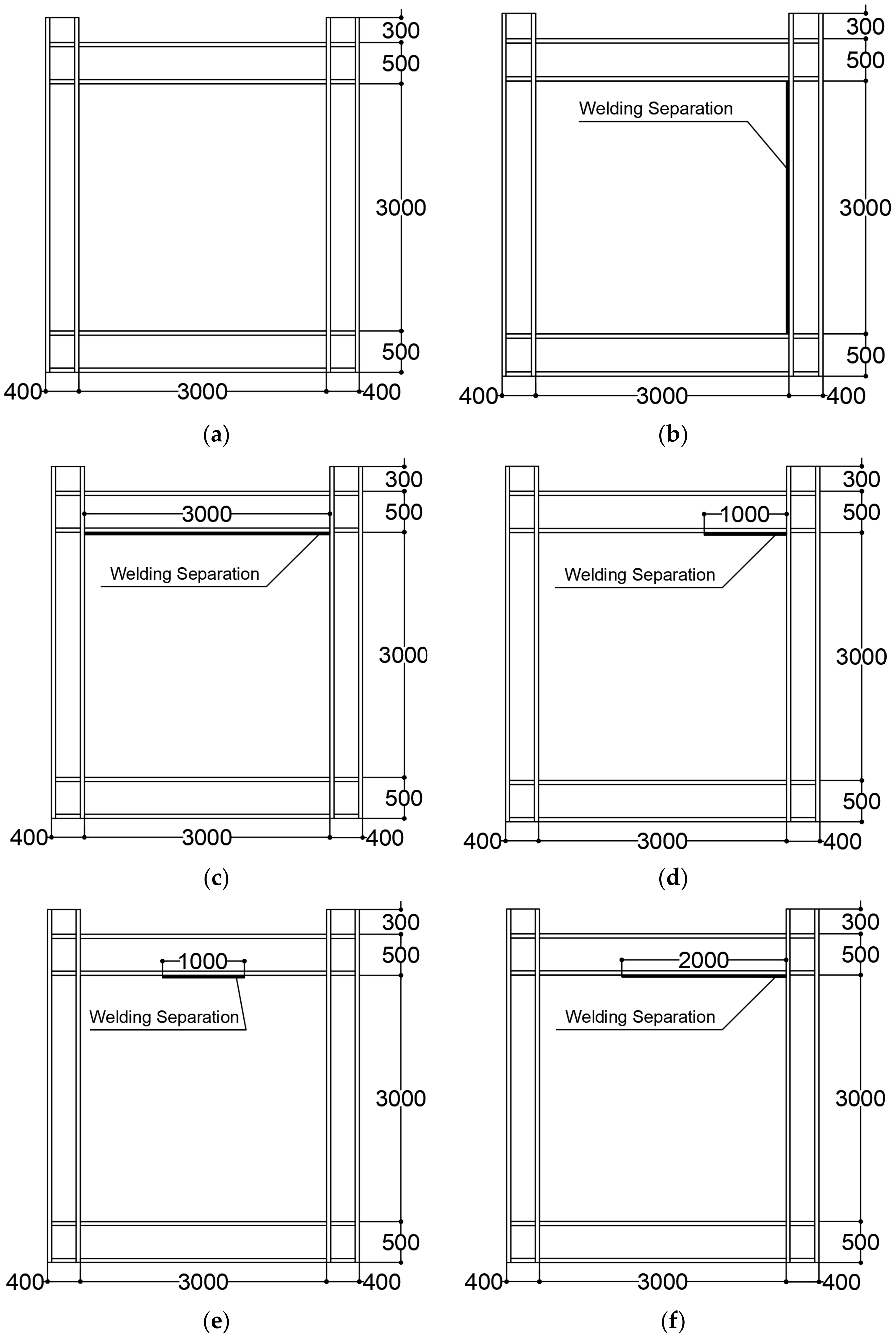
2. Problem Description

The parametric study was designed to study the effect of welding separation characteristics, as seen in Table 1. The boundary elements were designed according to the AISC Design Guide 20 [38,39]. The beam and the column sections were HM500 × 300 × 11 × 15 and HW400 × 400 × 13 × 21, respectively. The wall panels had a height of 3000 mm, a span of 3000 mm, and a thickness of 5 mm.
The symbols used to describe the samples were as follows:
  • SPt5 represents the case of a fully welded panel.
  • PS1 and PS2 represent the plate welding separation with one column and beam, respectively. The separation length was 3000 mm (whole length).
  • PS3 represents a corner beam separation with a length of 1000 mm.
  • PS4 represents a middle beam separation with a length of 1000 mm.
  • PS5 represents a corner beam separation with a length of 2000 mm.
Figure 2 provides the details for PS1, PS2, PS3, PS4, and PS5, including plate welding separation lengths and locations used in this parametric study. The parametric study values are shown.
The weld separation could be located randomly due to the effect of aging deterioration or manufacturing errors. However, separations due to excessive vertical and horizontal loads happen at the location of stress concentrations. A preliminary study was conducted to investigate the separation length that could provide a significant effect on the wall behavior. In models PS1 and PS2, the effects of the plate column and plate beam full separations were studied to find out which element separation had more effect on the USPSW seismic behavior. It was observed that the USPSW was more sensitive to beam welding separation than column welding separation, so the effect of the plate–beam welding separation was studied deeply in models PS3, PS4, and PS5. Model PS3 studied the plate corner separation, where tension fields started to form, and model PS4 studied the plate middle separation as the maximum out-of-plane deformation occurred at the plate center. For these models, the separation length was one-third of the plate width. However, longer cracks were used in model PS5 to represent the combination of plate corner and middle separations.

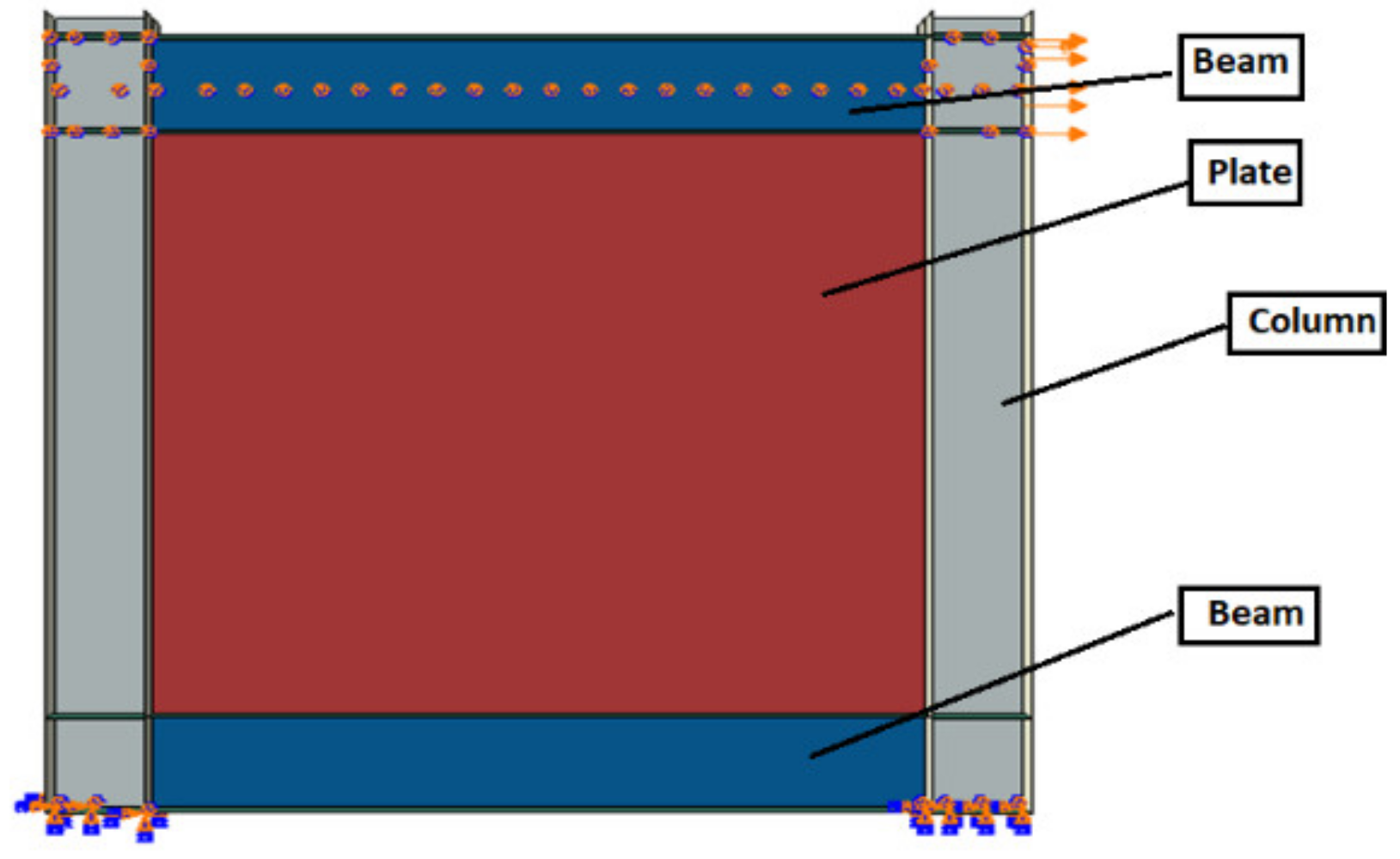
3. Finite Element Modeling

To study the nonlinear behaviors of USPSWs, SSPSWs, and CSPSWs, an accurate finite element (FE) analysis had to be conducted. The ABAQUS finite element code was used to perform the FE modeling in this study. The boundary frame and infill panel were modeled using quadrilateral shell elements (S4Rs), to avoid shear locking phenomena [40,41]. Shear locking phenomena can be defined as the unintentional generation of shearing deformation rather than the desired bending deformation. Therefore, the element becomes too stiff, and the overall deflections are lessened. This phenomenon can happen mainly with fully integrated, first-order, linear elements subjected to bending loads. It can be avoided by using higher-order elements such as quadratic elements rather than using linear elements if there is a bending load. Therefore, quadrilateral shell elements with reduced integration (S4R) were used [41,42]. Figure 3 shows the finite element modeling.
Details such as structural modeling, mechanical properties of materials, the boundary condition of models, and the time history of loading and initial defects are presented in this section.

3.1. Mechanical Properties of Steel Materials

For the parametric study, the isotropic hardening behavior was considered as a material model for the boundary frame and plate [41,43]. The boundary steel frame and infill panel materials had a yielding strength of 345 MPA and 235 MPA, respectively. The material’s specifications were as follows: elastic modulus E = 206,000 MPA; Poisson’s ratio ν = 0.3; hardening modulus Eh = E/100. The four-node shell element S4R with reduced integration was used for the modeling of all members. Material and geometric nonlinearities were taken into consideration in the analysis. After the material reached the yield point, the response of the system became nonlinear. Moreover, the response of the material under cyclic and monotonic loading was different; therefore, material nonlinearity had to be taken into consideration [44]. Due to the change in the out-of-plane deformation of the system during the loading process, geometric nonlinearity had to be taken into consideration. Reciprocating two-way tension fields snapped through the shape of the corrugated panel, which caused zero or negative stiffness.

3.2. Modal Analysis and Initial Defect

The out-of-plane initial defect or the initial imperfection, which may occur due to manufacturing, storage, and installation processes, had to be taken into consideration in the cyclic analysis, as it could have affected the plate strength. The initial imperfection was set as 1/1000 of the plate length based on previous research on thin USPSWs [45]. The ABAQUS command “Imperfection” was used to modify the coordinates of plate nodes using major buckling modes. The eigenvalue buckling analysis was used to evaluate the imperfection distribution over the panel by multiplying the first buckling mode by the scale factor.

3.3. Boundary Conditions and History Loading

The nonlinear cyclic analysis was conducted on groups of thin USPSWs, e.g., SPt5, PS1, PS2, PS3, PS4, and PS5. The lateral displacement was applied to the exterior column flange on the top-right panel zone. The lateral displacement was increased gradually to produce drift ratios of 0.25%, 0.5%, 1%, 1.5%, 2%, 2.5%, 3%, and 4%. Each amplitude was repeated twice, as shown in Figure 1b. The column base region had a fixed boundary condition, in which all these nodes were restrained in all directions. To prevent the buckling of the boundary beam, the out-of-plane displacement for the nodes of the beam centerline was constrained, as well as all the beam–column connection nodes. These constraints considered the out-of-plane bracing provided by the floor system.

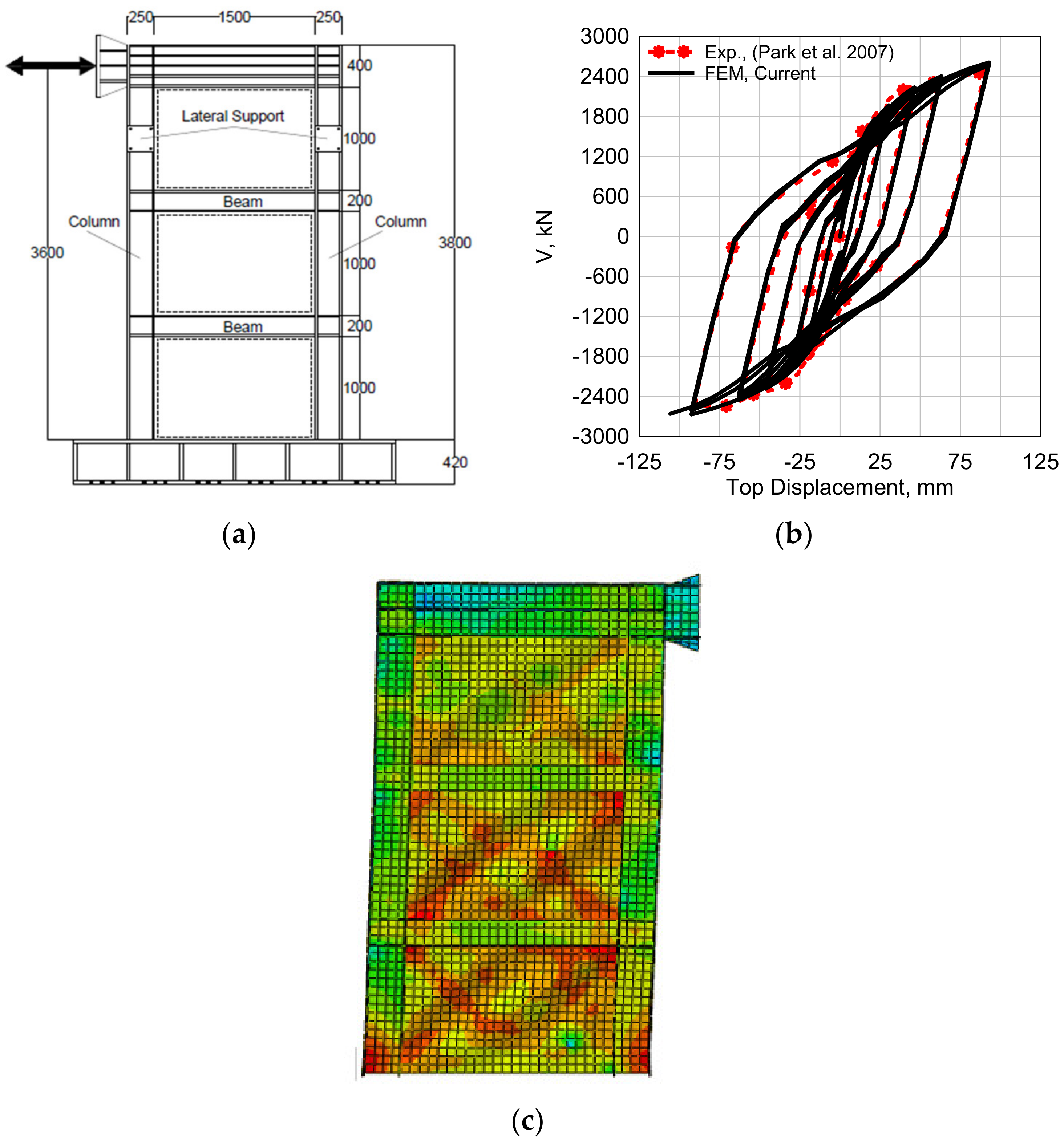
4. Experimental Work Validation

To verify the accuracy of the numerical simulation, previously published quasistatic test results were used. Finite element models were created, and the hysteretic curve and failure mode were compared to the experimental results.

4.1. Tested Specimen Description

Five SPSW specimens with a single bay and three stories were tested, and the specimen SC4T was selected for validation in this study [46]. The height, width, and thickness of the plates were 1000 mm, 1500 mm, and 5 mm, respectively. The section of the internal beams was H200 × 200 × 16 × 16 mm, and the top beam and columns sections were H400 × 200 × 16 × 16 and H250 × 250 × 20 × 20, respectively. The detailed dimensions of the specimen are shown in Figure 4a.

4.2. Numerical Simulation

The material used for the infill panels and boundary elements was steel SM490 with a yield stress of Fy = 330 MPa. The Chaboche constitutive model [47,48] was adopted; therefore, a combined hardening behavior was considered [41]. This rule had to be determined to perform a cyclic analysis and predict deformation behavior. In this rule, a combined hardening model included isotropic and nonlinear kinematic hardening [49]. In the Chaboche model, two parameters for isotropic hardening (i.e., Q∞ and b) and eight parameters for nonlinear kinematic hardening containing four back stresses (i.e., C1, γ1, C2, γ2, C3, γ3, C4, and γ4) had to be determined. The cyclic stress versus strain curve had to be used to determine the isotropic hardening parameters Q∞ and b. Therefore, Q∞ could be determined from the difference between cyclic and monotonic stress versus strain curves. The value of b could be determined from the fitting of peak stresses for each cycle. Whereas the parameters of the nonlinear kinematic hardening model could be determined from hysteretic strain-controlled round bar tensile tests [50]. Other cyclic hardening parameters of the material had to be assigned, such as the kinematic hardening modulus (C1 to C4), the rate at which the hardening modulus decreased with the plastic strain (γ), and the maximum change in the size of the yield surface (Q∞) [41]. The cyclic hardening parameters of the material are shown in Table 2. S4R elements were used to simulate the boundary frame and infill panel. The bottom of the model had a fixed boundary condition, and the initial out-of-plane defect was selected as 1/1000 of the steel plate height. The cyclic loading process is shown in Figure 1b, where the loading test was applied using the reference point in the middle of the upper beam until the system was destroyed completely.

4.3. Results and Discussion

The results showed that there was an agreement between the deformed shape of the proposed FEM and the experimental test for the sample SC4T (Figure 4a). The load–displacement curves for the experiment test and proposed FEM results can be seen in Figure 4b. The proposed FEM showed a hysteretic behavior similar to the experimental results with a difference in the load-carrying capacity of 4%. It could be concluded that the proposed numerical simulation could be used to predict the nonlinear behavior of SPSWs. In addition, the deformed shape of the sample is shown in Figure 4c.

5. Effect of Welding Separation Characteristics

To study the impact of welding separation/cracks on the seismic behavior of the SPSW, five FEMs with different welding separation characteristics were developed. Parameters such as lateral strength, energy dissipation capacity, and cyclic behavior were discussed. As the plane plate wall, such as the USPSW, was more sensitive to the boundary frame stiffness, the welding separation of the plane plate with the boundary frame was studied. The thicknesses of the plate and boundary frame elements remained the same as SPt5 for comparison reasons. Figure 2a shows the details of welding separation models PS1, PS2, PS3, PS4, and PS5, including the location and length of the separations.

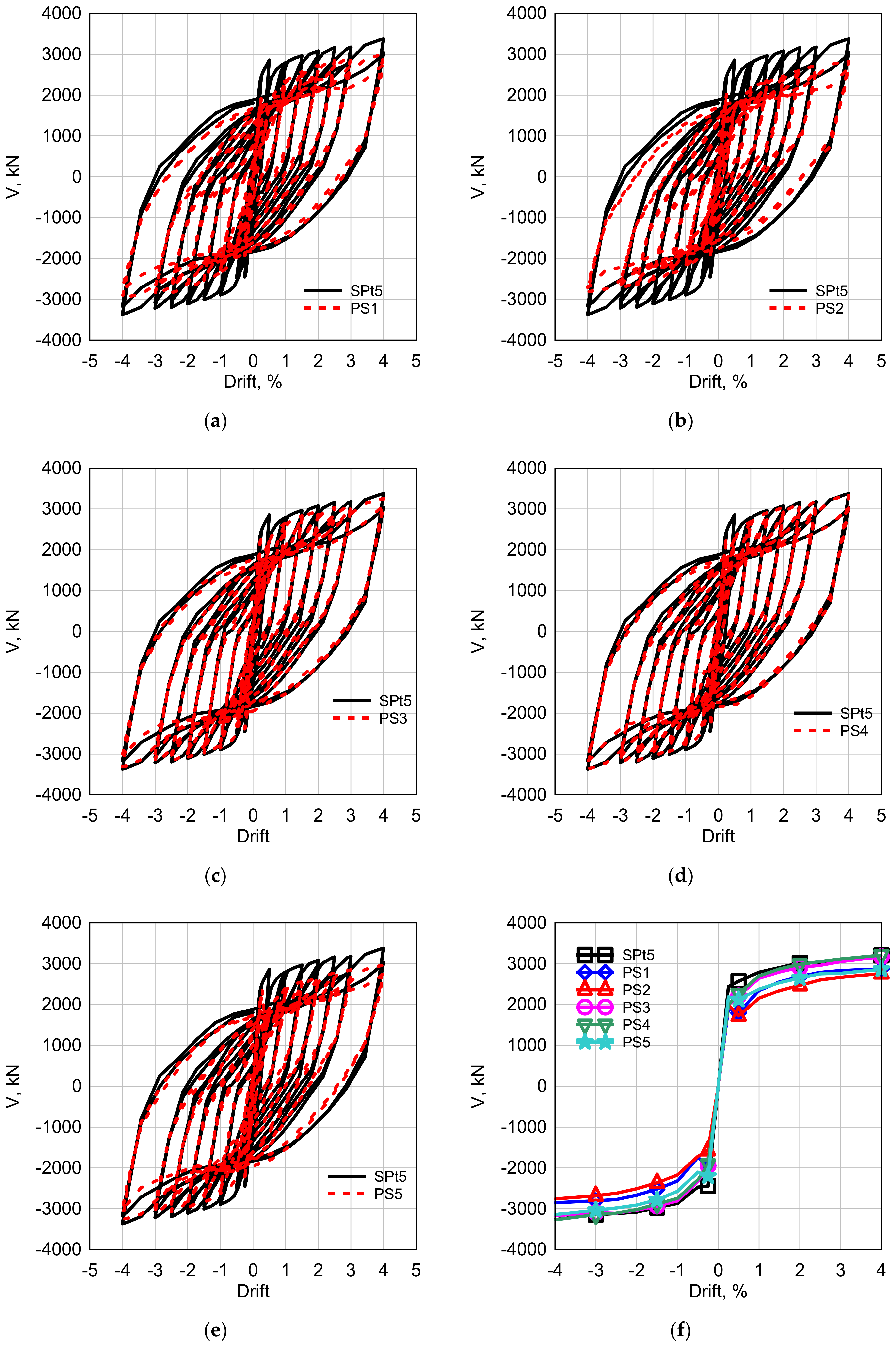
5.1. Hysteretic Behavior and Backbone Curves of Systems with Welding Separation

In Figure 5, the hysteretic curves of SPt5, PS1, PS2, PS3, PS4, and PS5 are presented and compared in this section. Figure 5a,b compare the hysteretic curve of wall SPt5 with cases PS1 and PS2. It can be observed that the weld separation caused a reduction in the load-carrying capacity values for cases PS1 and PS2 through the hysteretic relation. Additionally, the beam welding separation had a more significant effect on reducing the base shear than the column welding separation case. At a 0.25% drift, the reduction percentages for cases PS1 and PS2 were 21% and 36% in the push direction, respectively, where similar behavior was observed in the pull direction. In the case of a 4% drift in the push direction, similar behavior was observed with reduction percentages of 13% and 16% for PS1 and PS2, respectively. It could be concluded that the USPSW was more sensitive to beam welding separation than column welding separation, so the effect of plate–beam welding separation should be studied more deeply.
Hysteretic curves of plate–beam welding separation models with different separation lengths and locations in cases PS2, PS3, PS4, and PS5 are shown in Figure 5c–e. At a 0.25% drift in the push direction, the welding separation in cases PS3, PS4, and PS5 caused a reduction in the load-carrying capacity by 20%, 20%, and 10%. However, in the case of a 4% drift, this reduction was 3%, 0%, and 4%, respectively. It could be concluded that, in the early stages of cyclic loading, the separation had a significant effect on the load-carrying capacity, and this effect decayed by increasing the drift. At low values of drift, the wall mostly resisted the shear force through the contact between the plate and frame element, which caused the contact separation to be more effective. For a high drift value, the tension field action started at the nonseparated part, and the dependency on the contact decreased.
The backbone curves of PS1, PS2, PS3, PS4, and PS5 samples were extracted from the hysteretic curves, as shown in Figure 5f. The seismic behavior for different welding separation characteristics was evaluated using the loading function of Figure 1b and compared with the system without welding separation. Feature points were summarized from backbone curves, as shown in Table 3, using the method discussed in the first section.
In the push direction, it was found that the welding separation affected the initial stiffness of the walls. The separation caused stiffness degradation in walls PS1, PS2, PS3, PS4, and PS5 by percent values of 21, 36, 20, 22, and 10%, respectively. The cases of full-beam separation and 2000 mm corner separation showed the maximum and minimum reductions, respectively. Both cases of 1000 mm separation in the corner and middle had approximately the same reduction values. For the pull directions, the reduction ratios were 21, 18, 18, 18, and 10%, respectively, and the second cycle stiffness reduction ratios were 30%, 30%, 6%, 7%, and 15%, respectively. It seems that the plate welding separation had more of an effect on the system stiffness than the load-carrying capacity (base shear).

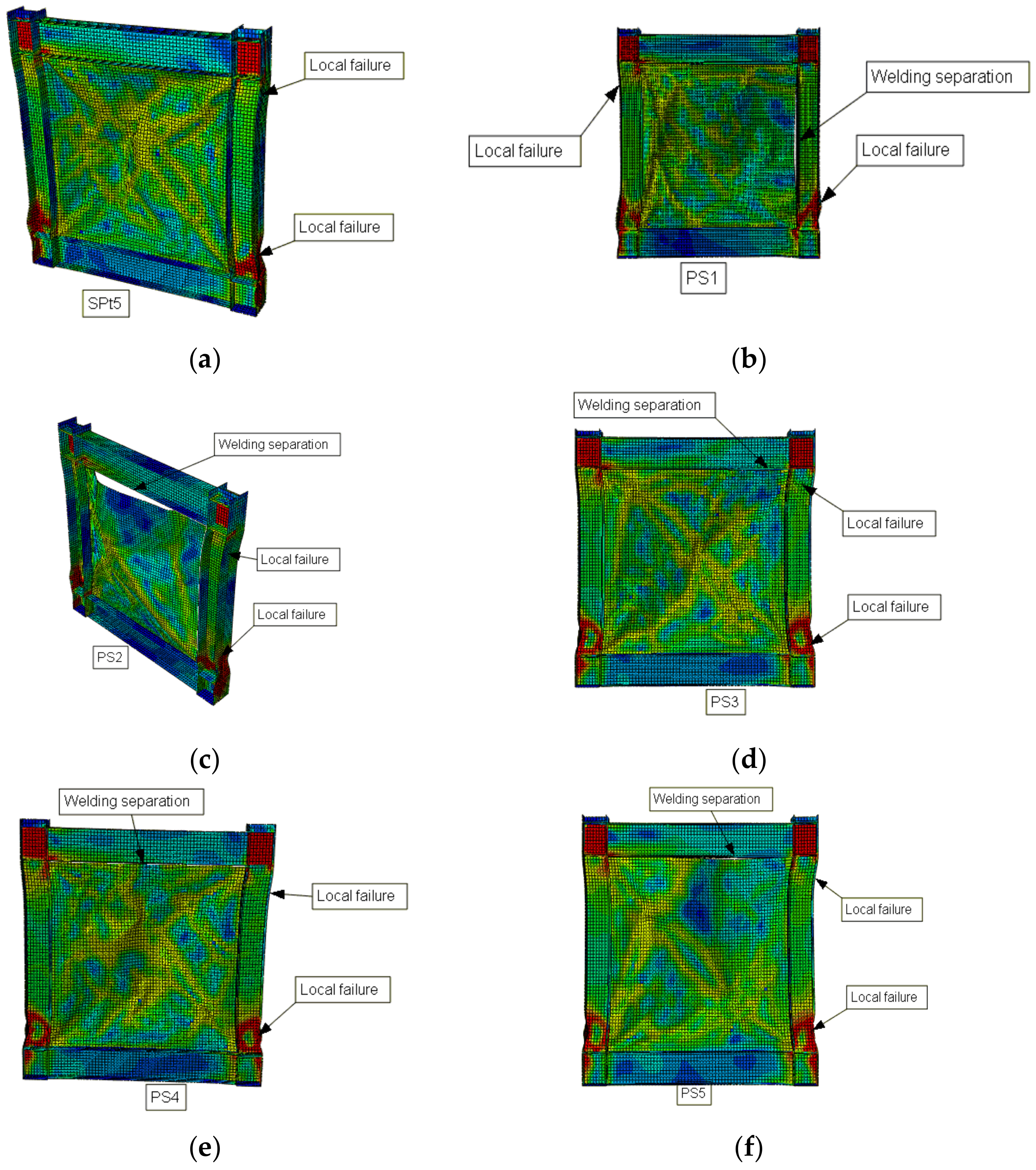
5.2. Failure Modes and Boundary Frame Demands

By comparing the PS1 and SPt5 backbone curves shown in Figure 5f whilst considering the Von-Mises stress distribution shown in Figure 6, it can be observed that the right portion of the plate that was separated from the column did not undergo high-stress demands. The plate–column separation led to fewer demand forces generated by the tension field action on the column. As a result, a smaller column section was required. It can be observed that there was a large stress concentration at the beam–column joint areas in the left portion of the plate that was connected to the boundary column, for which it should be designed for.
For the PS2 model, it can be seen that the concentration of the stress was mostly found in the plate–boundary connection areas. This might be attributed to incomplete tension field action that significantly decreased the plate’s postbuckling load-carrying capacity. The forces generated by the incomplete tension field action and gravity loads were concentrated in the columns. This produced a larger force demand, which the boundary columns should be designed for, while the top portion of the plate, which was separated from the top beam, did not undergo a high-stress concentration. As a result, a smaller top beam section was required.
In the case of the plate–column welding separation of PS1, local failure was not observed at the top of the column that had the welding separation (Figure 6b); the plate–column separation decreased the effect of the tension strips on the column. The plate–beam welding separation model PS2 had local buckling at the top and the bottom of the columns (Figure 6c). The top beam did not provide an anchor for the tension strips, due to the welding separation. High out-of-plane deformations were observed at the top of the plate. For partial plate–beam separation cases, i.e., PS3, PS4, and PS5, it was observed that the separated portions did not undergo significant high-stress demands. Incomplete tension field action was observed, which led to the partial plate’s postbuckling load-carrying capacity. In addition, they showed local buckling at the top and bottom of the columns. Welding separation progress was observed, as shown in Figure 6d–f.
In addition, the partial plate–beam separation in PS4 and PS5 negatively increased the stresses at the connected column–beam joint areas, leading to higher possibilities of early failure under seismic load. Increasing the separation length led to a large increase in stress concentrations at the connecting portions, which should be considered in the design.

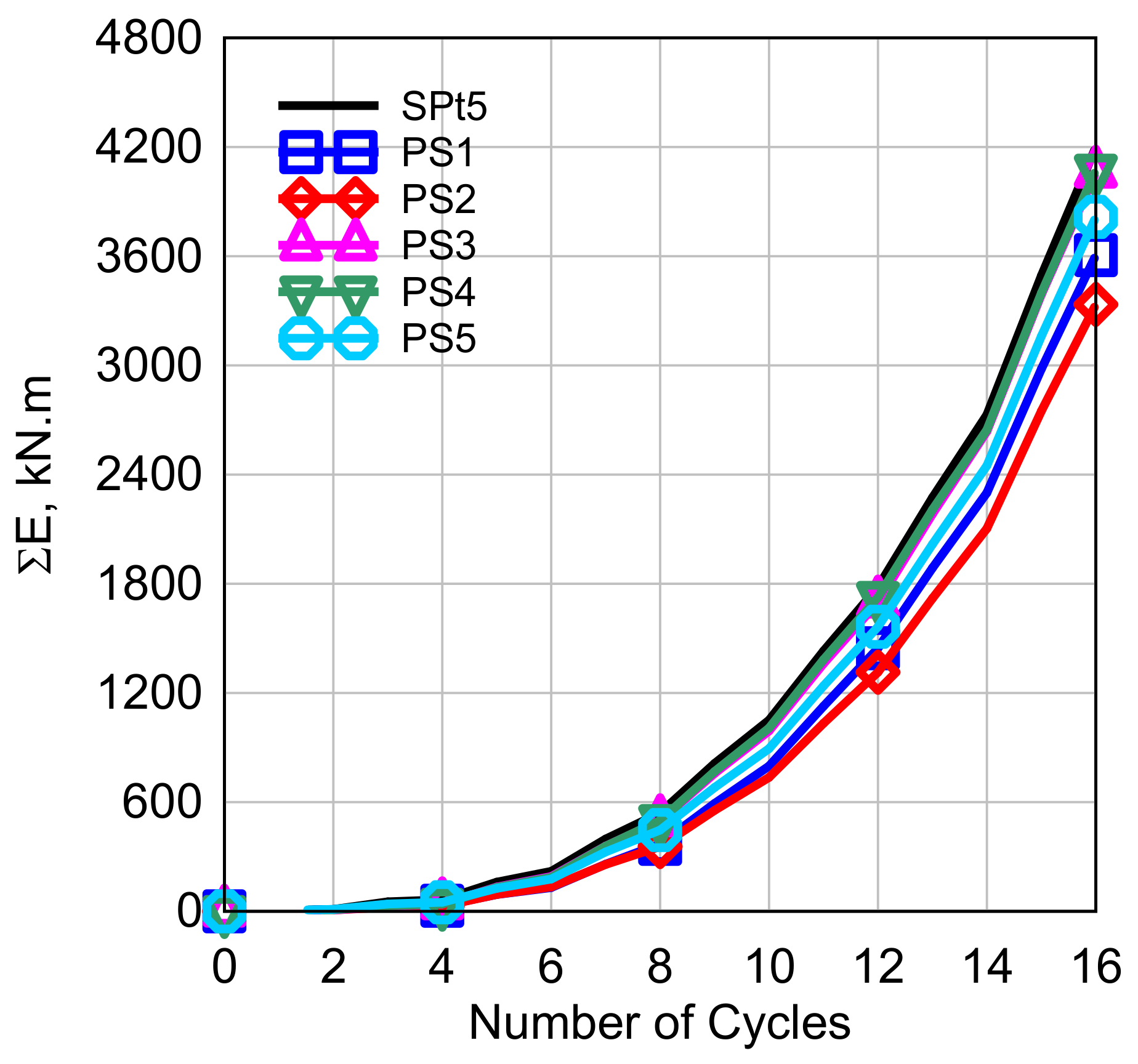
5.3. Energy Dissipation Capacity

The energy dissipation capacity reflects the seismic performance of the lateral resisting system. The energy dissipation capacity for each cycle was equal to the enclosed area of each hysteretic curve, in which the system with a plumper hysteretic curve had a higher energy dissipation capacity. Figure 7 shows the accumulated energy dissipation capacity for walls PS1, PS2, PS3, PS4, and PS5 with welding separations up to the cyclic number N = 16. It can be concluded that welding separation had a significant effect on the system’s energy dissipation capacity. The separation caused energy dissipation degradation in walls PS1, PS2, PS3, PS4, and PS5 by percentage values of 14, 21, 3.3, 2.9, and 9%, respectively. The cases of the full and middle beam separation had the maximum and minimum reduction values, respectively. The plate–beam corner separation had a slightly greater impact on the system energy dissipation capacity than the middle separation.

6. Conclusions and Future Research

In this paper, nonlinear cyclic analyses were conducted using a numerical simulation for SPSWs. The dimensions of the steel plates in this study were 3000 × 3000 mm2. Cracks were assumed to happen on the boundaries of the plate at the interface with the boundary frame. The main purpose of this paper was to study the effect of different welding separation characteristics between the infill plate and the boundary frame.
  • Finite element models were created and validated with published experimental and numerical works. The models were able to predict the previous results with a percentage error of 4%.
  • The separation had a significant effect on the seismic behavior in the early stages of cyclic loading, as the walls mostly resisted the shear force due to the plate–boundary frame contact before tension fields started at the nonseparated parts.
  • The USPSW system was more sensitive to the plate–beam separation than the plate–column one, especially the corner plate–beam separation.
  • When a full plate–column welding separation occurred, the initial stiffness, lateral strength, and energy dissipation capacity were reduced by approximately 21%, 13%, and 14%, respectively.
  • The system with the plate–beam separation had a lower initial stiffness, base shear capacity, and energy dissipation capacity of 36%, 16%, and 20.5%, respectively, compared to the systems with no separation.
  • Suggested lines of future research are as follows:
  • More studies on the effect of different structural characteristics, such as openings and slots on crack propagation.
  • Study the effect of different crack characteristics, such as the plate crack location, length, and angle.
  • Study the effect of cracks on corrugated and stiffened SPSW systems.
  • Study the effect of material properties on crack propagation.

Author Contributions

Conceptualization, H.M.M., O.A.S. and M.M.E.; methodology, H.M.M., A.A.E.-S. and M.M.E.; software, M.M.E., H.M.M. and A.A.E.-S.; validation, H.M.M., A.A.E.-S. and M.M.E.; formal analysis, H.M.M., A.A.E.-S. and M.M.E.; investigation, H.M.M., A.A.E.-S. and M.M.E.; resources, H.A.S. and A.A.E.-S.; data curation, O.A.S. and M.M.E.; writing—original draft preparation, M.M.E.; writing—review and editing, H.A.S., H.M.M., O.A.S. and A.A.E.-S.; visualization H.M.M.; supervision, H.M.M., O.A.S. and H.A.S.; project administration, H.M.M. and O.A.S.; funding acquisition, H.M.M., O.A.S. and H.A.S. All authors have read and agreed to the published version of the manuscript.

Funding

This research received no external funding.

Informed Consent Statement

Informed consent was obtained from all subjects involved in the study.

Conflicts of Interest

The authors declare no conflict of interest.

References

  1. Youssef, N.; Wilkerson, R.; Fischer, K.; Tunick, D. Seismic Performance of a 55-Storey Steel Plate Shear Wall. Struct. Des. Tall Spec. Build. 2010, 19, 139–165. [Google Scholar] [CrossRef]
  2. Yousuf, M.; Bagchi, A. Seismic Performance of a 20-Story Steel-Frame Building in Canada. Struct. Des. Tall Spec. Build. 2010, 19, 901–921. [Google Scholar] [CrossRef]
  3. Vian, D.; Bruneau, M.; Purba, R. Special Perforated Steel Plate Shear Walls with Reduced Beam Section Anchor Beams. II: Analysis and Design Recommendations. J. Struct. Eng. 2009, 135, 221–228. [Google Scholar] [CrossRef] [Green Version]
  4. Razzazzadeh, A.; Mashiri, F.R. Analysis of Steel Plate Shear Walls. Structural Engineering, Report. 107; Department of Civil Engineering, University of Alberta: Alberta, AB, Canada, 2012; pp. 549–554. [Google Scholar] [CrossRef]
  5. Alavi, E.; Nateghi, F. Experimental Study on Diagonally Stiffened Steel Plate Shear Walls with Central Perforation. J. Constr. Steel Res. 2013, 89, 9–20. [Google Scholar] [CrossRef]
  6. Driver, R.G.; Kulak, G.L.; Kennedy, D.J.L.; Elwi, A.E. Cyclic Test of Four-Story Steel Plate Shear Wall. J. Struct. Eng. 1998, 124, 112–120. [Google Scholar] [CrossRef]
  7. Nie, J.; Fan, J.; Liu, X.; Huang, Y. Comparative Study on Steel Plate Shear Walls Used in a High-Rise Building. J. Struct. Eng. 2013, 139, 85–97. [Google Scholar] [CrossRef]
  8. Hitaka, T.; Matsui, C. Experimental Study on Steel Shear Wall with Slits. J. Struct. Eng. 2003, 129, 586–595. [Google Scholar] [CrossRef]
  9. Chen, S.J.; Jhang, C. Experimental Study of Low-Yield-Point Steel Plate Shear Wall under in-Plane Load. J. Constr. Steel Res. 2011, 67, 977–985. [Google Scholar] [CrossRef]
  10. Caccese, V.; Elgaaly, M.; Chen, R. Experimental Study of Thin Steel-Plate Shear Walls under Cyclic Load. J. Struct. Eng. 1993, 119, 573–587. [Google Scholar] [CrossRef]
  11. Li, F.; Li, H.; Li, Z.M.; Li, Z.J.; Chen, X.F.; Ding, L. Cyclic Test of Diagonally Stiffened Steel Plate Shear Wall. Xi’an Jianzhu Keji Daxue Xuebao/J. Xi’an Univ. Archit. Technol. 2009, 41, 57–62. [Google Scholar]
  12. Alinia, M.M.; Dastfan, M. Cyclic Behaviour, Deformability and Rigidity of Stiffened Steel Shear Panels. J. Constr. Steel Res. 2007, 63, 554–563. [Google Scholar] [CrossRef]
  13. Choi, I.-R.; Park, H.-G. Steel Plate Shear Walls with Various Infill Plate Designs. J. Struct. Eng. 2009, 135, 785–796. [Google Scholar] [CrossRef]
  14. Shallan, O.; Maaly, H.; Elgiar, M.; Elsisi, A. Effect of Stiffener Characteristics on the Seismic Behavior and Fracture Tendency of Steel Shear Walls. Frattura Ed Integrità Strutturale 2020, 14, 104–115. [Google Scholar] [CrossRef]
  15. Broujerdian, V.; Ghamari, A.; Ghadami, A. An Investigation into Crack and Its Growth on the Seismic Behavior of Steel Shear Walls. Thin-Walled Struct. 2016, 101, 205–212. [Google Scholar] [CrossRef]
  16. Qu, B.; Bruneau, M.; Lin, C.-H.; Tsai, K.-C. Testing of Full-Scale Two-Story Steel Plate Shear Wall with Reduced Beam Section Connections and Composite Floors. J. Struct. Eng. 2008, 134, 364–373. [Google Scholar] [CrossRef]
  17. Guendel, M.; Hoffmeister, B.; Feldmann, M. Experimental and Numerical Investigations on Steel Shear Walls for Seismic Retrofitting. In Proceedings of the 8th International Conference on Structural Dynamics, Eurodyn 2011, Leuven, Belgium, 4–6 July 2011; pp. 474–481. [Google Scholar]
  18. Alavi, E.; Nateghi, F. Experimental Study of Diagonally Stiffened Steel Plate Shear Walls. J. Struct. Eng. 2013, 139, 1795–1811. [Google Scholar] [CrossRef]
  19. Alinia, M.M.; Hosseinzadeh, S.A.A.; Habashi, H.R. Influence of Central Cracks on Buckling and Post-Buckling Behaviour of Shear Panels. Thin-Walled Struct. 2007, 45, 422–431. [Google Scholar] [CrossRef]
  20. Alinia, M.M.; Hosseinzadeh, S.A.A.; Habashi, H.R. Buckling and Post-Buckling Strength of Shear Panels Degraded by near Border Cracks. J. Constr. Steel Res. 2008, 64, 1483–1494. [Google Scholar] [CrossRef]
  21. Wang, B.; Jiang, H. Experimental Study on Seismic Performance of Steel Plate Reinforced Concrete Tubes under Cyclic Loading. Proc. Struct. Des. Tall Spec. Build. 2017, 26. [Google Scholar] [CrossRef]
  22. Hosseinzadeh, L.; Emami, F.; Mofid, M. Experimental Investigation on the Behavior of Corrugated Steel Shear Wall Subjected to the Different Angle of Trapezoidal Plate. Struct. Des. Tall Spec. Build. 2017, 26, e1390. [Google Scholar] [CrossRef]
  23. Hosseinzadeh, L.; Mofid, M.; Aziminejad, A.; Emami, F. Elastic Interactive Buckling Strength of Corrugated Steel Shear Wall under Pure Shear Force. Struct. Des. Tall Spec. Build. 2017, 26, e1357. [Google Scholar] [CrossRef]
  24. Hatami, F.; Ghamari, A.; Rahai, A. Investigating the Properties of Steel Shear Walls Reinforced with Carbon Fiber Polymers (CFRP). J. Constr. Steel Res. 2012, 70, 36–42. [Google Scholar] [CrossRef]
  25. Sih, G.C.; Lee, Y.D. Tensile and Compressive Buckling of Plates Weakened by Cracks. Theor. Appl. Fract. Mech. 1986, 6, 129–138. [Google Scholar] [CrossRef]
  26. Shaw, D.; Huang, Y.H. Buckling Behavior of a Central Cracked Thin Plate under Tension. Eng. Fract. Mech. 1990, 35, 1019–1027. [Google Scholar] [CrossRef]
  27. Riks, E.; Rankin, C.C.; Brogan, F.A. The Buckling Behavior of a Central Crack in a Plate under Tension. Eng. Fract. Mech. 1992, 43, 529–548. [Google Scholar] [CrossRef] [Green Version]
  28. Alinia, M.M.; Dastfan, M. Behaviour of Thin Steel Plate Shear Walls Regarding Frame Members. J. Constr. Steel Res. 2006, 62, 730–738. [Google Scholar] [CrossRef]
  29. Vetr, M.G.; Ghamari, A.; Bouwkamp, J. Investigating the Nonlinear Behavior of Eccentrically Braced Frame with Vertical Shear Links (V-EBF). J. Build. Eng. 2017, 10, 47–59. [Google Scholar] [CrossRef]
  30. Bert, C.W.; Devarakonda, K.K. Buckling of Rectangular Plates Subjected to Nonlinearly Distributed In-Plane Loading. Int. J. Solids Struct. 2003, 40, 4097–4106. [Google Scholar] [CrossRef]
  31. Paik, J.K.; Kumar, Y.V.S.; Lee, J.M. Ultimate Strength of Cracked Plate Elements under Axial Compression or Tension. Thin-Walled. Struct. 2005, 43, 237–272. [Google Scholar] [CrossRef]
  32. Friedl, N.; Rammerstorfer, F.G.; Fischer, F.D. Buckling of Stretched Strips. Comput. Struct. 2000, 78, 185–190. [Google Scholar] [CrossRef]
  33. Guz, A.N.; Dyshel, M.S. Fracture and Buckling of Thin Panels with Edge Crack in Tension. Theor. Appl. Fract. Mech. 2001, 36, 57–60. [Google Scholar] [CrossRef]
  34. Brighenti, R. Buckling of Cracked Thin-Plates under Tension or Compression. Thin-Walled. Struct. 2005, 43, 209–224. [Google Scholar] [CrossRef]
  35. Khaloo, A.; Foroutani, M.; Ghamari, A. Influence of Diagonal Stiffeners on the Response of Steel Plate Shear Walls (SPSWs) Considering Crack Propagation. Bull. Earthq. Eng. 2019, 17, 5291–5312. [Google Scholar] [CrossRef]
  36. Khaloo, A.; Foroutani, M.; Ghamari, A. Influence of Crack on the Steel Plate Shear Walls Strengthened by Diagonal Stiffeners. Struct. Des. Tall Spec. Build. 2020, 29, e1716. [Google Scholar] [CrossRef]
  37. Paslar, N.; Farzampour, A.; Hatami, F. Infill Plate Interconnection Effects on the Structural Behavior of Steel Plate Shear Walls. Thin-Walled Struct. 2020, 149, 106621. [Google Scholar] [CrossRef]
  38. Bailey, B.N.; Delaney-Black, V.; Hannigan, J.H.; Ager, J.; Sokol, R.J.; Covington, C.Y. Somatic Complaints in Children and Community Violence Exposure. J. Dev. Behav. Pediatr. 2005, 26, 341–348. [Google Scholar] [CrossRef] [PubMed]
  39. AISC. (2016). Seismic Provisions for Structural Steel Buildings. In American Institute of Steel Construction, Inc. Available online: https://global.ihs.com/doc_detail.cfm?document_name=AISC%20341&item_s_key=00561564 (accessed on 1 May 2022).
  40. Tessler, A.; Spiridigliozzi, L. Resolving Membrane and Shear Locking Phenomena in Curved Shear-deformable Axisymmetric Shell Elements. Int. J. Numer. Methods Eng. 1988, 26, 1071–1086. [Google Scholar] [CrossRef]
  41. Nathan, A.J.; Scobell, A. How China Sees America. Foreign Aff. 2012, 91, 32. [Google Scholar] [CrossRef]
  42. El-Sisi, A.E.-D.A.; El-Husseiny, O.M.; Matar, E.B.; Sallam, H.E.-D.M.; Salim, H.A. Field-Testing and Numerical Simulation of Vantage Steel Bridge. J. Civ. Struct. Health Monit. 2020, 10, 443–456. [Google Scholar] [CrossRef]
  43. Sallam, H.E.M.; Matar, E.B.; El-Sisi, A.E.; El-Hussieny, O.M. Crack Tip Plasticity of Short Fatigue Crack Emanating from Riveted/Bolted Steel Connections. In Proceedings of the 13th International Conference on Structural and Geotechnical Engineering (ICSGE), Cairo, Egypt, 27–29 December 2009. [Google Scholar]
  44. Shi, Y.; Wang, M.; Wang, Y. Experimental and Constitutive Model Study of Structural Steel under Cyclic Loading. J. Constr. Steel Res. 2011, 67, 1185–1197. [Google Scholar] [CrossRef]
  45. Nie, J.G.; Zhu, L.; Tao, M.X.; Tang, L. Shear Strength of Trapezoidal Corrugated Steel Webs. J. Constr. Steel Res. 2013, 85, 105–115. [Google Scholar] [CrossRef]
  46. Park, H.-G.; Kwack, J.-H.; Jeon, S.-W.; Kim, W.-K.; Choi, I.-R. Framed Steel Plate Wall Behavior under Cyclic Lateral Loading. J. Struct. Eng. 2007, 133, 378–388. [Google Scholar] [CrossRef]
  47. Chaboche, J.L. Time-Independent Constitutive Theories for Cyclic Plasticity. Int. J. Plast. 1986, 2, 149–188. [Google Scholar] [CrossRef]
  48. Chaboche, J.L. Constitutive Equations for Cyclic Plasticity and Cyclic Viscoplasticity. Int. J. Plast. 1989, 5, 247–302. [Google Scholar] [CrossRef]
  49. Chaboche, J.L.; Van, K.D.; Cordier, G. Modelization of the Strain Memory Effect on the Cyclic Hardening of 316 Stainless Steel. In Proceedings of the Transactions of the International Conference on Structural Mechanics in Reactor Technology; INIS: Lausanne, Switzerland, 1979. [Google Scholar]
  50. Ryu, H.W.; Kim, H.T.; Kim, Y.J.; Kim, J.W. Determination of Combined Hardening Parameters to Simulate Deformation Behavior of C(T) Specimen under Cyclic Loading. Proc. Procedia Struct. Integr. 2018, 13, 1932–1939. [Google Scholar] [CrossRef]
Figure 1. Geometry and loading; (a) typical parts of SPSW; (b) loading function.
Buildings 12 00879 g001
Figure 2. Details of plate welding separation characteristics; (a) SPt5; (b) PS1; (c) PS2; (d) PS3; (e) PS4; (f) PS5 (dimensions in mm).
Buildings 12 00879 g002
Figure 3. Finite element model.
Buildings 12 00879 g003
Figure 4. FEM validation; (a) Specimen details (dimensions in mm); (b) comparison between numerical and experimental results; (c) FEM model deformed shape.
Buildings 12 00879 g004
Figure 5. Comparisons between hysteretic and backbone curves; (a) SPt5 vs. PS1; (b) SPt5 vs. PS2; (c) SPt5 vs. PS3; (d) SPt5 vs. PS4; (e) SPt5 vs. PS5; (f) backbone curves.
Buildings 12 00879 g005
Figure 6. Failure modes: (a) SPt5; (b) PS1; (c) PS2; (d) PS3; (e) PS4; (f) PS5.
Buildings 12 00879 g006
Figure 7. Accumulated energy dissipation capacity.
Buildings 12 00879 g007
Table 1. Details of the parametric study.
Models ID Welding Separation
LocationLength (mm)
PS1Full Column3000
PS2Full Beam3000
PS3Corner Beam1000
PS4Middle Beam1000
PS5Corner and Middle Beam2000
Table 2. Hardening parameters of materials (ABAQUS).
ParameterValue, N/mm2ParameterValue
Q21b1.2
C17993γ1175
C26773γ2116
C32854γ334
C41450γ429
C1 to C4 is the kinematic hardening modulus, γ is the rate at which the hardening modulus decreased with the plastic strain, Q is the maximum change in the size of the yield surface, and b is the rate at which initial yield stress changed with the plastic strain.
Table 3. Cyclic results of steel walls with different welding separation characteristics.
ModelLoad DirectionKi (kN/mm)K2 (kN/mm)Δy (mm)Vy (kN)Δm (mm)Vm (kN)
SPt5push −300.77152.12162479.51303267.17
pull +299.91158.1162855.21303203.4
PS1push −238.9107.48.121958.21302852.6
pull +235.4110.68.1219391302868.6
PS2push −193.47105.858.122000.51302759.1
pull +245.171068.122016.81302757.5
PS3push −239.81143.68.122384.21303173.23
pull +244.61136.058.122367.91303169.91
PS4push −235.4141.138.122333.71303272.5
pull +245.9139.258.122310.151303207.81
PS5push −271.0129.4516.32143.61303144.28
pull +268.65130.348.122204.11302860.98
Ki and K2 are the second cyclic stiffnesses, Δy and Vy represent yield displacement and force, and Δm and Vm represent maximum lateral displacement and shear capacities.
Publisher’s Note: MDPI stays neutral with regard to jurisdictional claims in published maps and institutional affiliations.

