Article

Axial Load Enhancement of Lightweight Aggregate Concrete (LAC) Using Environmentally Sustainable Composites

1
Department of Civil and Environmental Engineering, Faculty of Engineering, Srinakharinwirot University, Nakhonnayok 26120, Thailand
2
Department of Civil Engineering, University of Management and Technology, Lahore 54770, Pakistan
3
Department of Civil Engineering, Faculty of Engineering and Built Environment, Universiti Kebangsaan, Malaysia (UKM), Bangi 43600, Malaysia
4
Thammasat Research Unit in Infrastructure Inspection and Monitoring, Repair and Strengthening (IIMRS), Thammasat School of Engineering, Faculty of Engineering, Thammasat University Rangsit, Klong Luang, Pathumthani 12000, Thailand
5
Construction Innovations and Future Infrastructure Research Center (CIFIR), Department of Civil Engineering, Faculty of Engineering, King Mongkut’s University of Technology Thonburi, Bangkok 10140, Thailand
6
Center of Excellence in Earthquake Engineering and Vibration, Department of Civil Engineering, Chulalongkorn University, Bangkok 10330, Thailand
*
Author to whom correspondence should be addressed.
Buildings 2022, 12(6), 851; https://doi.org/10.3390/buildings12060851
Submission received: 26 May 2022 / Revised: 14 June 2022 / Accepted: 15 June 2022 / Published: 17 June 2022
(This article belongs to the Special Issue Strength and Performance of Building Materials)

Abstract

:
Salient features of lightweight aggregate concrete (LAC) include noticeable fire resistance, high strength-to-weight ratio, and low magnitude of dead loads. Further, LAC has a low cost, eases construction practices, and possesses an environment-friendly nature. On the downside, LAC has substandard mechanical properties in comparison to normal aggregate concrete. Natural fiber-reinforced polymers (FRPs) have shown their potential in ameliorating the mechanical properties of natural aggregate concrete. So far, no study has been conducted to assess the efficacy of hemp rope confinement to strengthen lightweight aggregate concrete especially comprising rectilinear sections. This study aimed to overcome the substandard nature of LAC. A low-cost, sustainable, and environmentally green solution in the form of natural hemp rope layers is proposed. Twenty-four square concrete specimens were tested in three groups depending upon the presence and quantity of lightweight aggregates. It was found that concrete constructed with lightweight aggregates demonstrated lower ultimate compressive strength and strain as compared to normal aggregate concrete. Hemp rope-confined LAC showed enhanced ultimate compressive strength and strain. This enhancement was found to increase with the number of hemp rope layers. Several existing ultimate stress models were assessed to predict the ultimate compressive strength of the hemp rope-confined specimens. Only a single model was able to predict the ultimate compressive strength of the hemp rope-confined specimens with reasonable accuracy.

1. Introduction

Concrete constructed with lightweight aggregates (LAC) has higher porosity and lower bulk density than natural aggregate concrete. It presents a distinctive distribution of air voids inside the aggregates and concrete mix. Further, the quality of the bond between aggregates and concrete mix is influenced by aggregate particle saturation [1]. Salient features of LAC include noticeable fire resistance, high strength-to-weight ratio, and low magnitude of dead loads [2]. LAC offers low costs, eases construction practices, and possesses an environment-friendly nature [3]. Considerable attention has been paid towards the use of lightweight aggregate concrete in recent years [4,5,6,7]. Noticeable shortcomings associated with LAC include its brittle nature and low-grade deformation capacity [8]. It has been reported that LAC has a 30–35% lower weight than natural aggregate concrete. Consequently, this has a detrimental effect on its mechanical properties [9]. It is acknowledged that the density of concrete plays an important role when deciding on its use in structural applications [10]. Disadvantages like its brittle nature, low fracture toughness, and low tensile-to-compressive strength ratio limit its use in structural applications [11,12,13,14,15].
Lightweight aggregates are prone to fracture at lower load levels than natural aggregates. This premature fracture of lightweight aggregates can be prevented if passive lateral confinement is applied. It is well known that confinement results in an increase of axial compressive strength and ductility [16,17]. Such confinement results in the increase of the synergetic effect between lightweight aggregates and concrete mix [18]. Khaloo et al. [19] examined the behavior of LAC confined with single or interlocking double spiral hoops. Their results revealed that the slope of the post-peak axial compressive stress–strain response improved, resulting in an increase of axial compressive ductility. Zhou et al. investigated the efficacy of Fiber-Reinforced Polymer (FRP) confinement on athe xial compressive behavior of LAC. It was observed that with one, two, and three layers of FRP, the compressive strength of LAC increased by a factor of 2.6, 2.1, and 5.4, respectively [9]. Dabbagh et al. [2] confined LAC cylinders with glass FRP and carbon FRP sheets. The axial compressive behavior of LAC was substantially improved as the number of external FRP layers increased. Synthetic fiber-reinforced polymers (FRPs) have been used extensively in the strengthening of natural aggregate concrete [20,21,22,23,24]. Synthetic FRPs have also shown their potential in the strengthening of recycled aggregate concrete [25,26,27,28]. Two major issues have been associated with synthetic FRPs. The first issue is related to their massive costs [29,30] that inhibits them to be used for small-scale projects. The second issue is related to their production process that involves the use of chemicals that may cause skin problems, including irritant and allergic contact dermatitis [31,32,33]. In recent years, several researchers have highlighted the potential of natural FRPs in replacing conventional synthetic FRPs [34,35].
Characteristically, natural FRPs involve a substantial reduction in costs in comparison to synthetic FRPs [36,37,38]. Hussain et al. [39] examined the efficacy of jute, sisal, and hemp fibers to improve the compressive stress–strain behavior of concrete. The results revealed that hemp fibers outperformed jute and sisal in terms of compressive strength enhancement. Fragoudakis et al. [40] noticed that hemp fibers resulted in an increase in bending strain and corresponding deflection of concrete beams. Ramadan et al. [41] concluded that hemp fiber confinement resulted in an increase of axial strength and ductility. Ghalieh et al. [42] studied concrete columns wrapped with hemp ropes. They also observed increased ultimate compressive strength and ductility in hemp-confined columns in comparison control columns. So far, no study has been conducted to assess the efficacy of hemp rope confinement to strengthen lightweight aggregate concrete especially comprising rectilinear sections. This study aims to fill this gap and to extend the application of natural fiber ropes to strengthen lightweight aggregate concrete. The objectives of this study included: (1) to increase the ultimate compressive strength and corresponding strain of lightweight aggregate concrete, (2) to improve the post-peak behavior of the compressive stress–strain response, and (3) to assess the accuracy of existing numerical ultimate strength models in predicting the peak compressive strength of lightweight aggregate concrete externally confined with hemp fiber ropes.

2. Experimental Program

2.1. Test Matrix

This study presents an experimental program conducted on 24 square shape specimens. As shown in Table 1, 24 specimens were tested in 3 groups. Group 1, 2, and 3 comprised lightweight aggregate amounts of 0%, 50%, and 100%, respectively. This amount represents the percentage amount of natural aggregates that was replaced by the lighweight aggregates. In each group, 2 specimens were tested in as-built condition and served as reference for the remaining specimens. As for the remaining specimens, two specimens each were strengthened with 1, 2, and 3 layers of hemp fiber ropes.
A four-part nomenclature was adopted to represent a strengthened specimen type. The first part, i.e., “SQ” is common for all specimens, representing the square shape. The second part denotes the percentage amount of lightweight aggregates, i.e., 0%, 50%, or 100%. The third part, i.e., “H” is, again, common, representing hemp fiber rope confinement, whereas the last part indicates the number of hemp fiber rope layers. For reference specimens in each group, the 3rd and 4th parts were merged to a single term, i.e., “CONT”. Further details are summarized in Table 1.

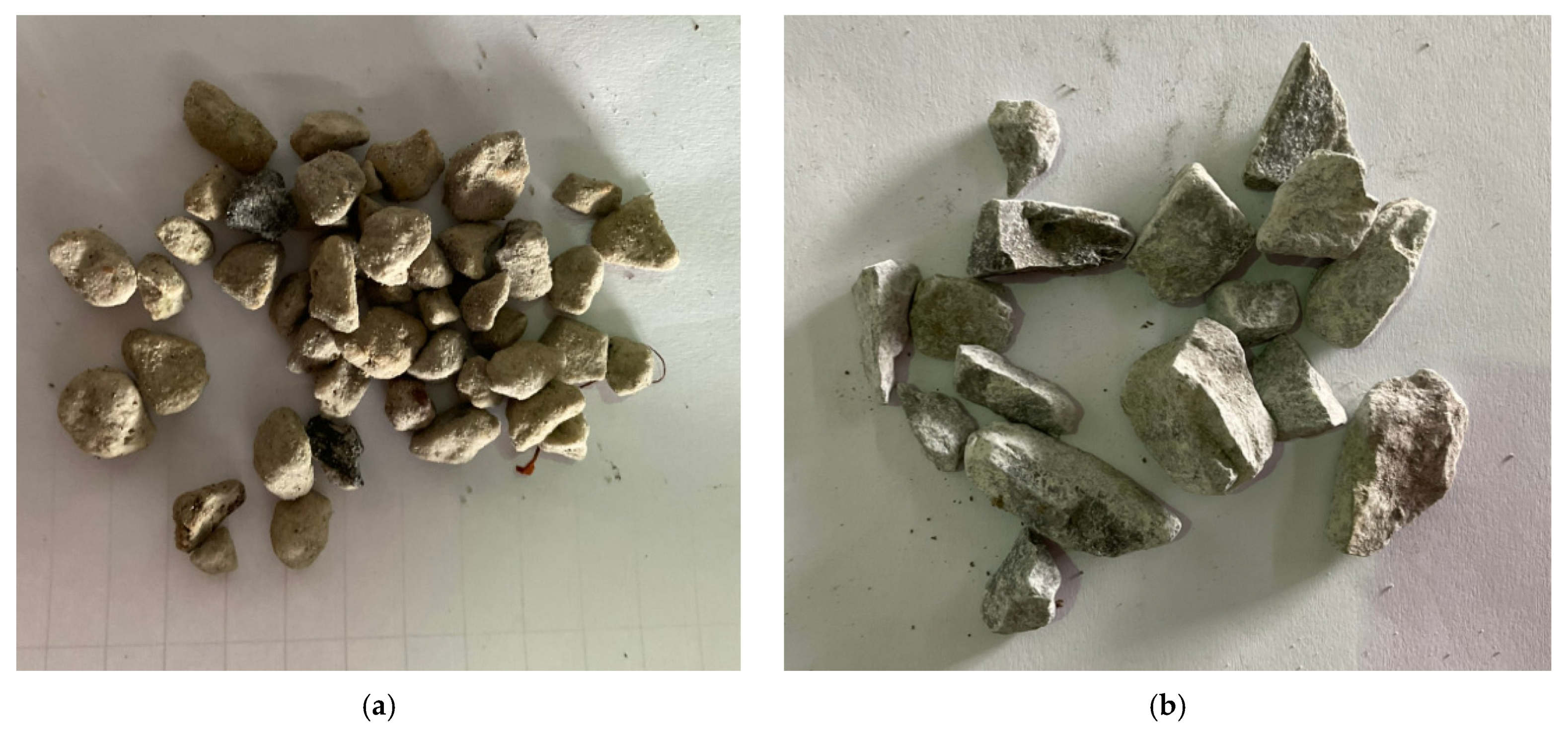
2.2. Material Properties

Concrete in this study contained type-1 Portland cement. Both the fine and the coarse natural aggregates were locally acquired. The nominal maximum size of the natural coarse aggregate was limited to 25 mm. The size of the lightweight aggregates ranged from 12 mm to 18 mm, and they were obtained from INSEE Thailand. The concrete mix proportions of each of the three groups are presented in Table 2. Figure 1 shows the natural and lightweight aggregates used in this study.
Figure 2 shows the test setup adopted to estimate the mechanical properties of the hemp ropes. A Universal Testing Machine (UTM) of 2 MN capacity was used to stretch the hemp ropes. A load was applied at a speed of 4 kN/s. Moreover, two steel plates were fixed to the ends of each specimen before the application of the load. The purpose of these plates was to safeguard the rope fiber shell from the danger of accidental load transfer at large strain levels. The applied load intensity was monitored using a calibrated load cell. The average tensile strength of the hemp rope was estimated around to be 750 N, whereas the corresponding elongation was 2.2 mm.

2.3. Specimen Details

Since the target specimen shape was square in this study, it was necessary to consider the corner effects. Several studies have highlighted that a sharp corner in rectilinear sections reduces the efficiency of external confinement, and the corresponding confinement efficiency is strongly related to the curvature available at the corners [43,44,45]. Considering this, a corner radius of 13 mm was provided in all specimens. A typical section size was 150 × 150 mm, whereas the height was 300 mm.

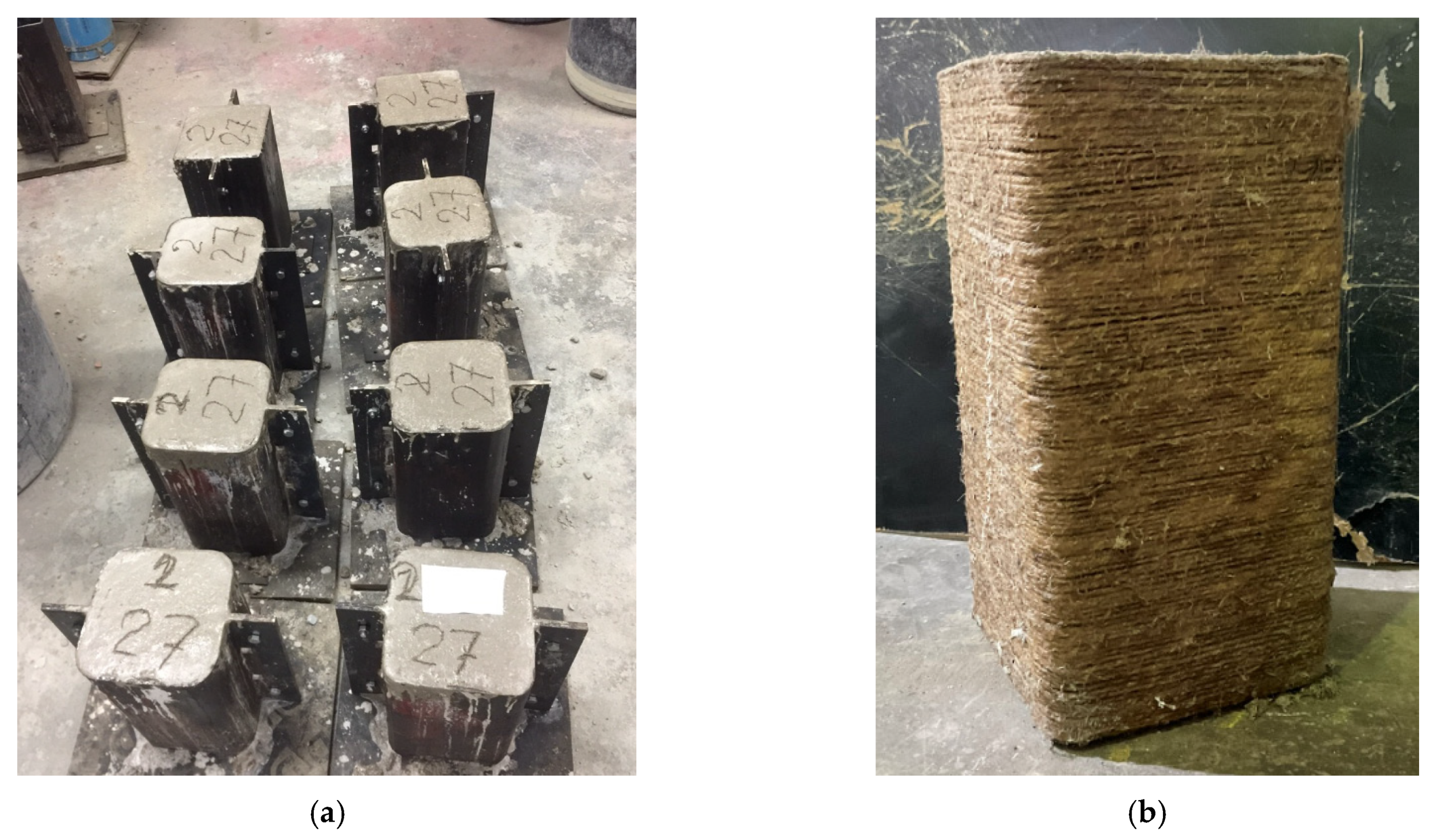
2.4. Construction and Strengthening of the Specimens

Steel molds were used to construct the test specimens (see Figure 3a). Concrete was filled in each mold in three equal layers. A vibration table was used to compact the concrete after the pouring of each layer. After 1 day of casting, LAC gained sufficient strength for the molds to be removed. Curing of the specimens was conducted in the laboratory environment for 28 days. After 28 days of casting, the hemp fiber ropes were wrapped around the specimens. Before applying the hemp ropes, the surface of the specimens was properly cleaned. A polyester resin was applied onto the concrete surface using a hand brush. Then, one end of the hemp rope was glued to the concrete surface using a super glue to inhibit any superfluous slip. The hemp ropes were hand-tightened while wrapped around the specimens. Special attention was paid to avoid any gap between consecutive hemp rope layers. After reaching the other end of the specimen, the end of the hemp rope was again glued to the concrete surface. At this point, the wrapped hemp ropes were impregnated with polyester resin. A similar procedure was repeated to wrap subsequent layers of the hemp ropes. Figure 3b presents a typical specimen strengthened with hemp fiber ropes.

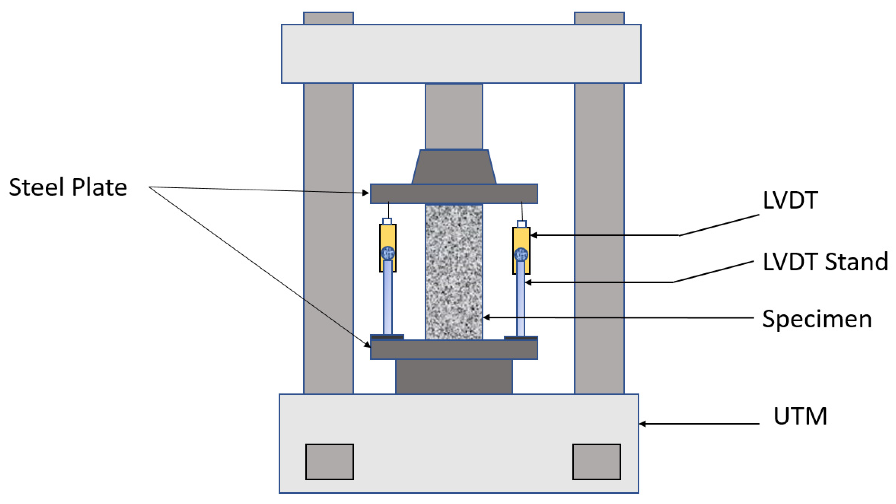
2.5. Test Setup and Instrumentation

A Universal Testing Machine (UTM) was used to exert a monotonic compressive load on each specimen. The top and bottom sides of each specimen were cleaned and smoothened before placing the specimen inside the UTM. Load concentration was achieved by placing steel plates above and below the concrete specimen. Figure 4 presents a typical test setup adopted in this study. Two Linear Variable Displacement Transducers (LVDTs) were used to monitor the axial shortening of each specimen under the compressive loads. The tips of the LVDTs were pointed to the top steel plates.

3. Experimental Results

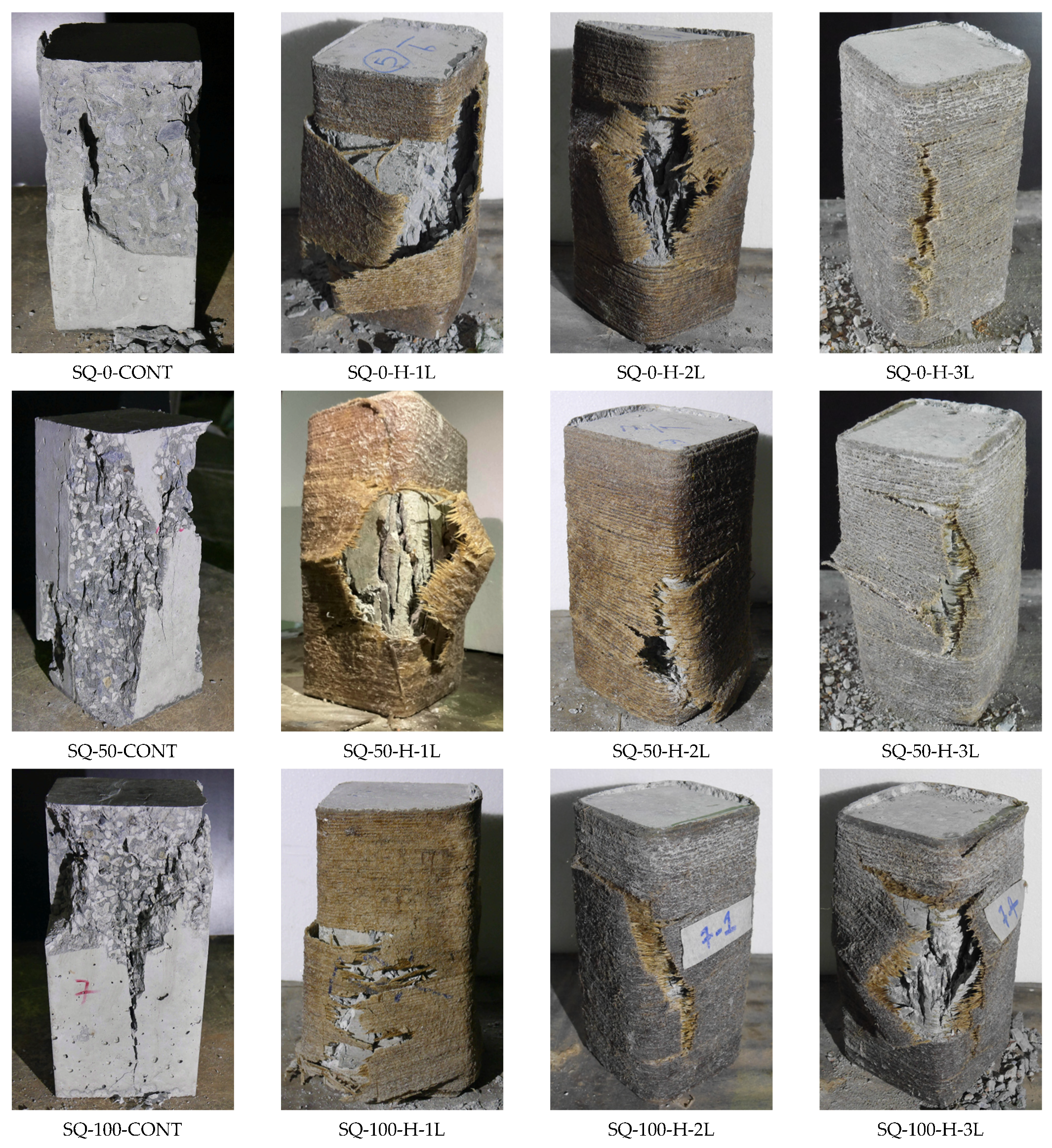
3.1. Ultimate Failure Modes

In group 1, specimen SQ-0-CONT neither included lightweight aggregates nor experienced external confinement. Its failure accompanied the sudden crushing of concrete. Specimen SQ-0-H-1L was strengthened with one layer of hemp ropes. Its failure accompanied the tensile rupture of the hemp ropes in the hoop direction. The location of the tensile rupture was observed in the middle of its side, indicating that the provision of a 13   mm corner radius provided an adequate corner curvature to inhibit a premature hemp rope failure due to the knife action. Specimens SQ-0-H-2L and SQ-0-H-3L were confined with two and three layers of hemp ropes, respectively. These specimens also exhibited tensile rupture of the hemp ropes in the hoop direction. However, unlike the sudden failure of the hemp ropes in the specimen SQ-0-H-1L, the ultimate failure in these specimens was progressive. Snapping sounds were heard, indicating the rupture of the underlying layers before the tensile failure of the outermost layers. Further, the failure of one- and two-layer confined specimens was more explosive than that of three-layer confined specimens. Crushing of the concrete underneath the hemp ropes could also be observed for specimens SQ-0-CONT and SQ-0-H-1L.
Specimens in group 2 were fabricated by replacing 50% of natural aggregates with lightweight aggregates. The control specimen SQ-50-CONT exhibited a more brittle failure than its counterpart specimen in group 1, indicating the substandard nature of the lightweight aggregates. The ultimate failure in the case of the hemp rope-confined specimens was significantly delayed, demonstrating the efficacy of the hemp ropes in imparting axial ductility to LAC. The ultimate failures of hemp rope-confined specimens were again dominated by the tensile rupture of the hemp ropes in the hoop direction. The control specimen in group 3, i.e., SQ-100-CONT was fabricated by replacing 100% of natural coarse aggregates by the lightweight aggregates. Crushing of the concrete was mainly confined within the top half, whereas no traces of crushing were observed within the bottom half. Splitting of the concrete was observed along the full height of the specimen. Hemp rope-confined specimens failed because of the tensile rupture of the hemp ropes but not before imparting significant ductility to the LAC specimens. Figure 5 summarizes the ultimate failure modes of all specimens.

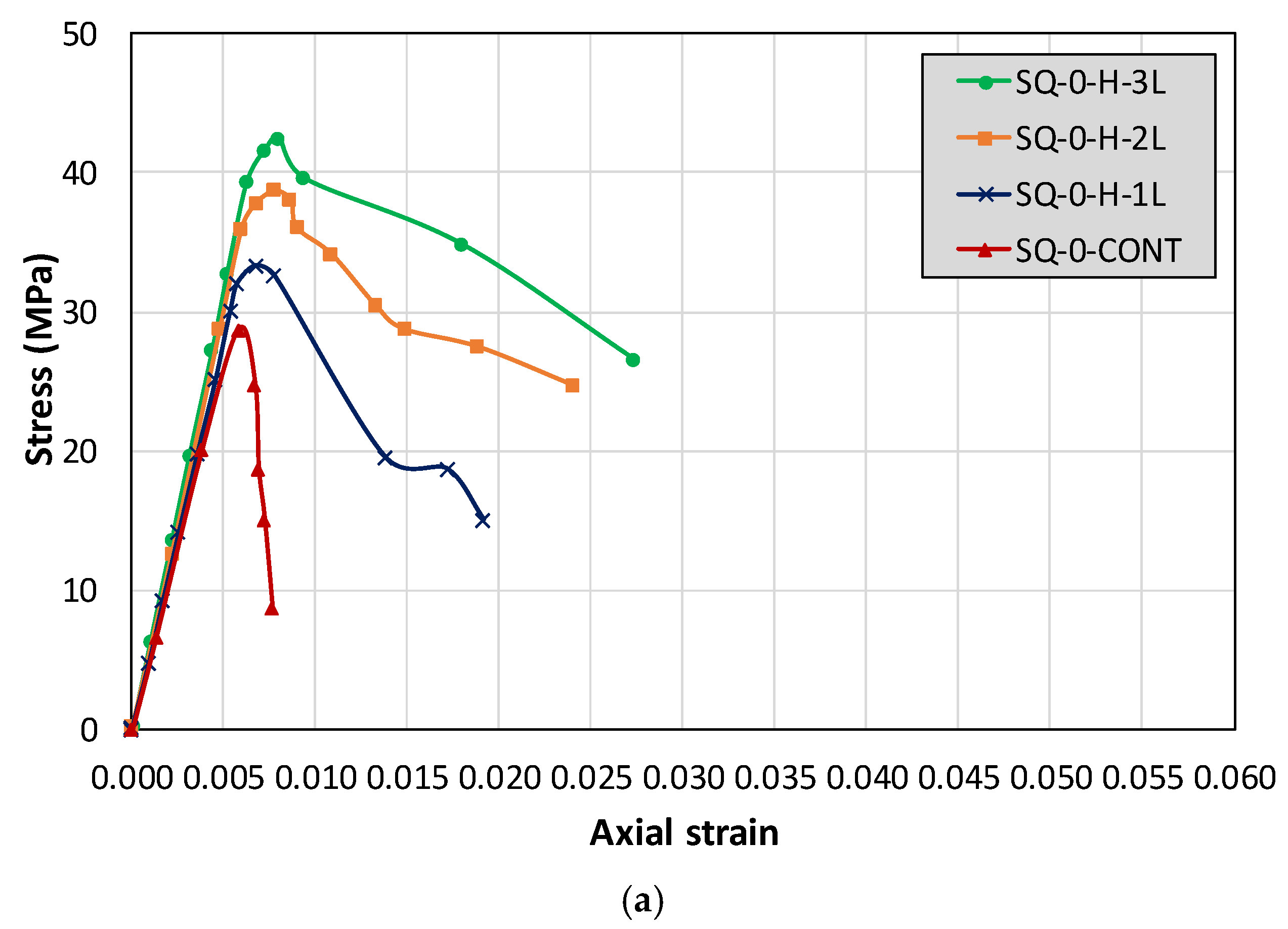
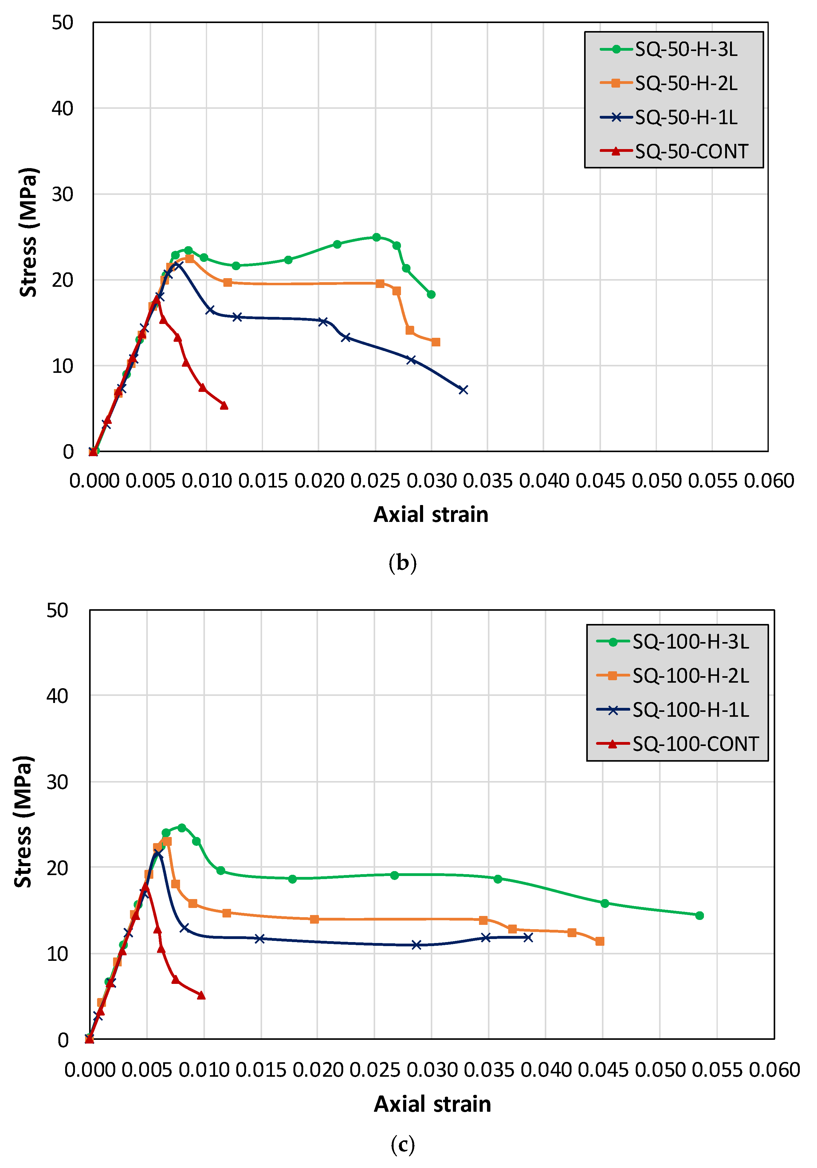
3.2. Compressive Stress–Strain Relationship

Figure 6a–c represent the axial compressive stress–strain relationships of group 1, 2, and 3, respectively. In Figure 6a, it is evident that the control specimen SQ-0-CONT experienced a brittle failure. Its stress–strain relation comprised a steep ascending branch followed by an abrupt drop in its axial capacity. Characteristically, strains corresponding to the peak axial strength and failure were inseparable. This suggests that the control specimen did not exhibit any ductility. On the contrary, specimens confined with one, two, and three hemp rope layers showed not only increased peak axial strengths but also improved post-peak stress–strain relation. It is evident in Figure 6a that the descent in the post-peak slope became milder with the increase in external hemp rope layers. Nonetheless, irrespective of the number of external hemp rope layers, the post-peak response was characterized by a descending branch in group 1 specimens.
The control specimen in group 2 also exhibited a brittle stress–strain response. From visual inspection, it could be observed that the peak load sustained by the control specimen SQ-50-CONT was lower than that sustained by the specimen SQ-0-CONT. This suggests that the inclusion of lightweight aggregates had a direct impact on the peak axial compressive strength. Interestingly, the post-peak behavior of hemp rope-confined specimens in group 2 exhibited a plateau after a slight drop in the peak strength. It is evident that the ultimate strain range for this plateau increased as the number of hemp rope layers increased. Further, the specimen confined with three layers of hemp rope (i.e., SQ-50-H-3L) was able to regain its peak strength after the initial drop.
Characteristically, the shape of the axial stress–strain response of group 3 specimens was identical to that of group 2. A noticeable difference was observed in the post-peak compressive stress–strain response of hemp rope-confined specimens. After the initial drop in peak strength, the residual compressive strength was sustained at larger strain levels compared to group 2 specimens. This can be summarized as follows: group 1 specimens did not incorporate any lightweight aggregates, and no plateau was observed in their post-peak compressive stress–strain relation. This plateau started to appear as 50% of the natural aggregates were replaced by the lightweight aggregates (see Figure 6b). The range of this plateau increased as the quantity of lightweight aggregates increased to 100% in group 3 specimens (see Figure 6c).

3.3. Ultimate Stress and Strain Values

Table 3 presents the ultimate compressive stress and corresponding strain values for all specimens. It also summarizes the increase (%) in ultimate compressive stress and strain for hemp rope-confined specimens. In the case of 0% lightweight aggregates (i.e., group 1), one, two, and three layers of hemp ropes increased the ultimate peak strengths by 19%, 40%, and 52%, respectively. The corresponding increase in the strain was 16%, 33%, and 37%, respectively. For group 2 specimens, the increase in ultimate strength for one, two, and three layers of hemp ropes resulted in an increase of 16%, 27%, and 37%, respectively, whereas the corresponding strain increased by 37%, 55%, and 255%, respectively. Finally, an increase of 21%, 30%, and 38% in ultimate strength was observed for one, two, and three wraps of hemp ropes when 100% of natural coarse aggregates were replaced by lightweight aggregates. The increase in ultimate strain for the specimen SQ-50-H-3L was 355%. However, for the specimen SQ-100-H-3L, only a 65% increase in ultimate strain was observed.
It can be observed that the increase in ultimate strength of group 3 specimens was slightly higher than that of group 2 specimens. It is recalled that 100% of natural coarse aggregates were replaced by lightweight aggregates in group 3, whereas this replacement ratio was only 50% in group 2. Subsequently, the peak compressive strength sustained by the control specimen in group 3 was lower than that of group 2 control specimen (i.e., specimens SQ-50-CONT and SQ-100-CONT sustained 18.22 and 17.78 MPa ultimate compressive strength, respectively). As a result, the increase in the ultimate compressive strength of group 3 confined specimens was slightly higher than that of group 2 specimens. However, a similar trend was not observed in compressive strains at peak sustained axial stresses.

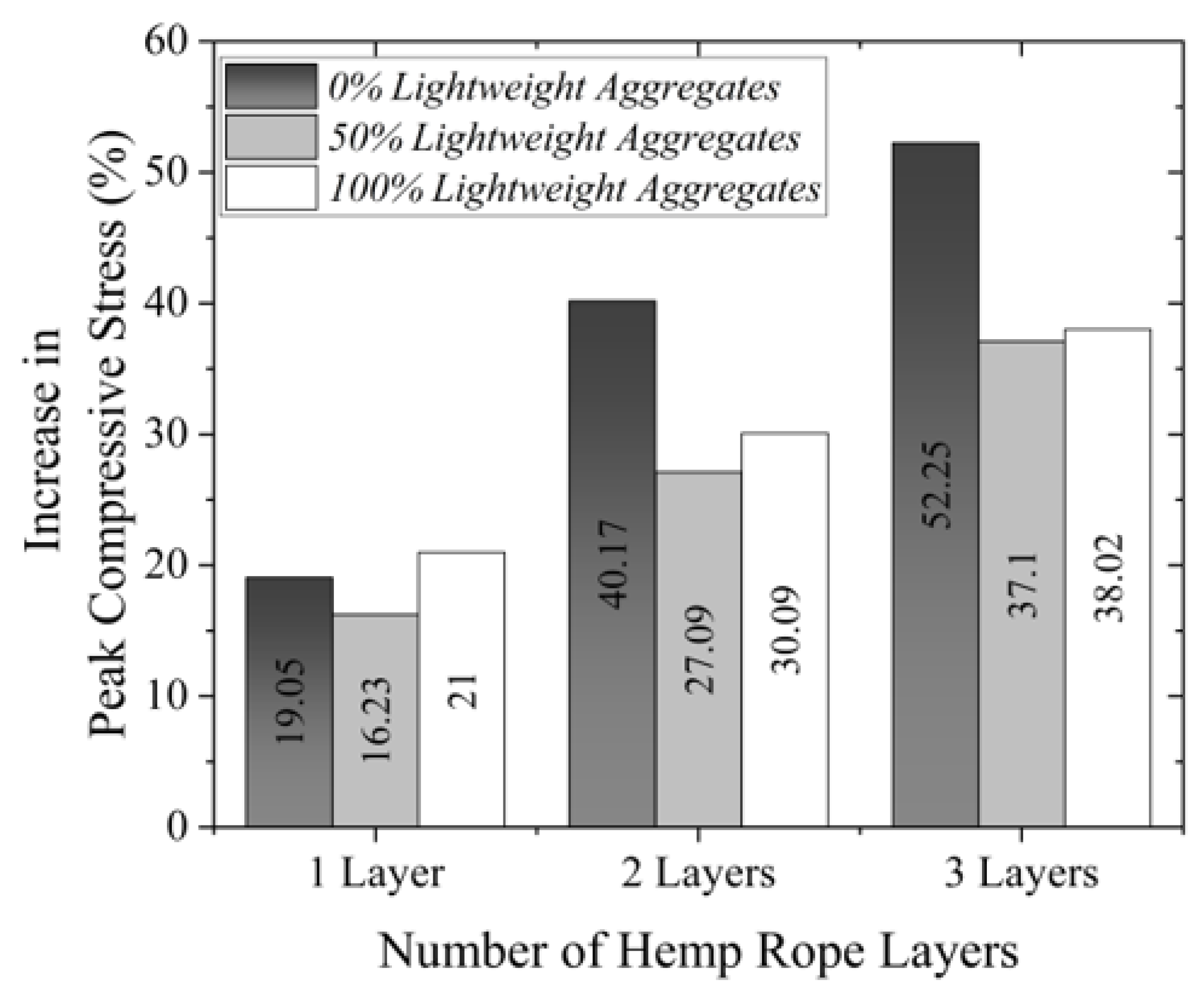
3.4. Effect of the Quantity of Lightweight Aggregates

This study replaced 50% and 100% of natural coarse aggregates with lightweight aggregates in group 2 and 3 specimens, respectively, whereas group 1 specimens did not contain lightweight aggregates. Figure 7 presents the effect of the lightweight aggregate content on the increase in ultimate compressive strength compared to the respective control specimens. It is evident that the maximum enhancement in compressive strength was observed for the case of 0% lightweight aggregate concrete. The increase in peak strength for group 3 specimens (i.e., 100% lightweight aggregates) was slightly higher than that of group 2 specimens (i.e., 50% lightweight aggregates). A careful observation of Table 3 suggested that the peak strength of the control specimen in group 2 was slightly higher than that of the group 3 control specimen, i.e., 18.22 and 17.78 for the control specimens of group 2 and 3, respectively. This slight difference may have resulted in the observed differences in ultimate strength gain between group 2 and group 3 hemp rope-confined specimens. Another important observation from Figure 7 is that irrespective of the number of hemp rope layers, the increase in ultimate compressive strength of lightweight aggregate concrete was always lower than that of normal aggregate concrete.

3.5. Analytical Investigations

In this section, the accuracy of several existing ultimate compressive strength models was assessed by comparing their predictions with experimental results. Several researchers have adopted the general form of Equation (1) to relate the amount of external passive confinement to the increase in ultimate compressive strength. The quantity of external confinement is related to the resulting generated confinement pressure f l .
f c c f c o = 1 + k 1 f l f c o  
where f c c and f c o are ultimate compressive strengths of confined and unconfined concrete, respectively, k 1 is a regression coefficient that varies from one model to another. Since hemp ropes are unidirectional (i.e., they possess tensile strength only), it is assumed that their confinement mechanism is analogous to that of a typical unidirectional FRP. With this assumption, several existing FRP confinement models can be applied to hemp rope confinement. From Figure 8, Equation (2) can be presented by considering an equilibrium between outward bursting forces and confinement stresses.
f l = 2 f t t D ρ  
where D , f t , and t represent the diagonal length of the section, the tensile strength of hemp fiber ropes, and the thickness of a single hemp rope, respectively. D and ρ can be determined from Equation (3) [46] and Equation (4) [47], respectively.
D = 2 b d b + d  
ρ = 1 ( b 2 R c ) 2 + ( d 2 R c ) 2 3 A  
where b and d are defined in Figure 8. R c is the corner radius, and A is defined in Equation (5).
A = b d ( 4 π ) R c 2  
Table 4 presents several existing ultimate compressive stress models for FRP confinement. Figure 9a–c present the comparison of the analytical and experimental results for the ultimate compressive strength of the specimens of group 1, 2, and 3, respectively.
Figure 9a presents the comparison of the analytical and experimental results for the ultimate compressive strength of group 1 specimens (i.e., 0% lightweight aggregates). From a visual inspection, it can be observed that the models of Toutanji et al. [55], Al-Salloum [50], and Lam and Teng [52] provided close approximates of the experimental results. In the case of 50% lightweight aggregates (i.e., group 2 specimens and Figure 9b), the model of Hussain et al. [46] resulted in good agreement with the experimental results, whereas no model seemed to predict the experimental results of group 3 specimens with consistency (see Figure 9c). In this study, three statistical indicators were used to evaluate the performance of the considered existing models: (1) Mean Square Error, (2) Average Absolute Error, and (3) and standard deviation as determined from Equations (6)–(8) [56].
M S E = i = 1 N [ a n a i e x p i e x p i ] 2 N  
A A E = i = 1 N | a n a i e x p i e x p i | N  
S D = i = 1 N ( a n a i e x p i a n a a v g e x p a v g ) 2 N  
where a n a and e x p represent analytical and experimental values, respectively. N is the total number of observations, and i is the ith observation. The results of the statistical indicators for various models are shown in Figure 10. For group 1 specimens, the model of Mirmiran et al. [46] and Pimanmas et al. [53] provided the lowest MSE, AAE, and SD values. In the model of Mirmiran et al. [46], the values of MSE, AAE, and SD for group 1 specimens were 0.17, 3.84, and 1.32%, respectively, whereas the corresponding values in the model of Pimanmas et al. [48] were 0.09, 2.61, and 1.32, respectively. For the case of 50% lightweight aggregates (i.e., group 2), the performance of the existing models was better than that for the case of 0% lightweight aggregates. The lowest MSE, AAE, and SD were provided by the model of Hussain et al. [46]. For group 3 specimens that contained 100% coarse aggregates as lightweight, the performance of the model of Hussain et al. [46] was the best among all the considered models, as it provided MSE, AAE, and SD values of 0.26, 3.99, and 2.94, respectively.
In summary, the model of Hussain et al. [46] provided the closest approximation of the ultimate compressive strengths of hemp rope-confined lightweight aggregate concrete specimens. It must be stated that the model of Hussain et al. [46] was proposed for the case of hemp rope-confined normal aggregate concrete. Although, in the existing studies [56,57], theoretical stress-versus-strain curves were proposed, in this study only existing ultimate strength models were evaluated. Future studies will be carried out to develop theoretical stress–strain curves for hemp rope-confined lightweight aggregate concrete.

4. Conclusions

Recognizing the beneficial impacts of lightweight aggregates as a replacement of normal coarse aggregates in concrete, this study conducted an experimental analysis on 24 rectilinear concrete specimens. A low-cost and environmentally friendly solution in the form of natural hemp ropes was proposed to strengthen the substandard mechanical properties of lightweight aggregate concrete. The following conclusions can be drawn from the experimental results.
  • Concrete constructed with lightweight aggregates exhibited lower ultimate compressive strength and strain as compared to normal aggregate concrete. Specimens confined with hemp fiber ropes and constructed with lightweight aggregate concrete demonstrated a substantial increase in peak compressive strength and corresponding strain.
  • Specimens constructed with lightweight aggregate concrete and externally confined with hemp fiber ropes exhibited a flat plateau in their post peak compressive stress–strain response. This suggests that significant axial compressive ductility was imparted by the hemp ropes to the lightweight aggregate concrete, which is a vital desired characteristic of concrete that is subjected to dynamic loadings.
  • Natural coarse aggregates were replaced in the amount of 50% and 100% in group 2 and 3 specimens, respectively. Hemp fiber wraps resulted in an approximately similar gain in ultimate compressive strength and strain in both the groups. In terms of axial ductility, specimens constructed with 100% lightweight aggregates showed higher ductility compared to those constructed with 50% lightweight aggregates. This indicates that the efficacy of hemp fiber ropes in terms of imparting axial ductility improved as the amount of lightweight aggregates increased.
  • Several ultimate compressive models were assessed in this study to predict hemp rope-confined specimens’ compressive strengths. It was found that the model of Hussain et al. agreed well with the experimental results. Therefore, for design and analysis purposes of hemp rope-confined concrete, the model of Hussain et al. is recommended to predict the ultimate compressive strength of lightweight aggregate concrete.

Author Contributions

Funding acquisition, S.S., A.W.A.Z. and K.C.; Resources, M.U.R., E.Y. and P.J.; Writing–original draft, Q.H.; Writing–review & editing, N.A. All authors have read and agreed to the published version of the manuscript.

Funding

This research was funded by the Faculty of Engineering, Srinakharinwirot University, Thailand (Research Grant ID 192/2564).

Institutional Review Board Statement

Not applicable.

Acknowledgments

The authors of this research work are very grateful to the Faculty of Engineering, Srinakharinwirot University, Thailand, for providing research grant (Research Grant ID 192/2564) to carry out the research work. Thanks are also extended to the Siam City Cement Public Company Limited, Thailand for providing materials for this research. Thanks are also extended to the Research and Innovation Development Unit for Infrastructure and Rail Transportation Structural System (RIDIR), Srinakharinwirot University, Nakhonnayok, Thailand for supporting this research. The authors also like to extend their gratitude to the Asian Institute of Technology (AIT) for supporting test facilities.

Conflicts of Interest

The authors declare no conflict of interest.

References

  1. Kucharczyková, B.; Keršner, Z.; Pospíchal, O.; Misák, P.; Vymazal, T. Influence of Freeze–Thaw Cycles on Fracture Parameters Values of Lightweight Concrete. Procedia Eng. 2010, 2, 959–966. [Google Scholar] [CrossRef]
  2. Dabbagh, H.; Delshad, M.; Amoorezaei, K. Design-Oriented Stress-Strain Model for FRP-Confined Lightweight Aggregate Concrete. KSCE J. Civ. Eng. 2021, 25, 219–234. [Google Scholar] [CrossRef]
  3. Lo, T.Y.; Tang, W.C.; Cui, H.Z. The Effects of Aggregate Properties on Lightweight Concrete. Build. Environ. 2007, 42, 3025–3029. [Google Scholar] [CrossRef]
  4. Miller, N.M.; Tehrani, F.M. Mechanical Properties of Rubberized Lightweight Aggregate Concrete. Constr. Build. Mater. 2017, 147, 264–271. [Google Scholar] [CrossRef]
  5. Wang, J.; Zheng, K.; Cui, N.; Cheng, X.; Ren, K.; Hou, P.; Feng, L.; Zhou, Z.; Xie, N. Green and Durable Lightweight Aggregate Concrete: The Role of Waste and Recycled Materials. Materials 2020, 13, 3041. [Google Scholar] [CrossRef] [PubMed]
  6. Mo, K.H.; Ling, T.C.; Alengaram, U.J.; Yap, S.P.; Yuen, C.W. Overview of Supplementary Cementitious Materials Usage in Lightweight Aggregate Concrete. Constr. Build. Mater. 2017, 139, 403–418. [Google Scholar] [CrossRef]
  7. Wu, T.; Yang, X.; Wei, H.; Liu, X. Mechanical Properties and Microstructure of Lightweight Aggregate Concrete with and without Fibers. Constr. Build. Mater. 2019, 199, 526–539. [Google Scholar] [CrossRef]
  8. Lim, J.C.; Ozbakkaloglu, T. Stress–Strain Model for Normal- and Light-Weight Concretes under Uniaxial and Triaxial Compression. Constr. Build. Mater. 2014, 71, 492–509. [Google Scholar] [CrossRef]
  9. Zhou, Y.; Liu, X.; Xing, F.; Cui, H.; Sui, L. Axial Compressive Behavior of FRP-Confined Lightweight Aggregate Concrete: An Experimental Study and Stress-Strain Relation Model. Constr. Build. Mater. 2016, 119, 1–15. [Google Scholar] [CrossRef]
  10. Wang, H.T.; Wang, L.C. Experimental Study on Static and Dynamic Mechanical Properties of Steel Fiber Reinforced Lightweight Aggregate Concrete. Constr. Build. Mater. 2013, 38, 1146–1151. [Google Scholar] [CrossRef]
  11. Haque, M.N.; Al-Khaiat, H.; Kayali, O. Strength and Durability of Lightweight Concrete. Cem. Concr. Compos. 2004, 26, 307–314. [Google Scholar] [CrossRef]
  12. Rico, S.; Farshidpour, R.; Tehrani, F.M. State-of-the-Art Report on Fiber-Reinforced Lightweight Aggregate Concrete Masonry. Adv. Civ. Eng. 2017, 2017, 8078346. [Google Scholar] [CrossRef] [Green Version]
  13. Deifalla, A.; Awad, A.; Seleem, H.; Abdelrahman, A. Investigating the Behavior of Lightweight Foamed Concrete T-Beams under Torsion, Shear, and Flexure. Eng. Struct. 2020, 219, 110741. [Google Scholar] [CrossRef]
  14. Deifalla, A.; Awad, A.; Seleem, H.; Abdelrahman, A. Experimental and Numerical Investigation of the Behavior of LWFC L-Girders under Combined Torsion. Structures 2020, 26, 362–377. [Google Scholar] [CrossRef]
  15. Yang, X.; Wu, T.; Liu, X. Stress–Strain Model for Lightweight Aggregate Concrete Reinforced with Carbon–Polypropylene Hybrid Fibers. Polymers 2022, 14, 1675. [Google Scholar] [CrossRef] [PubMed]
  16. Wenchen, M. Behavior of Aged Reinforced Concrete Columns Under High Sustained Concentric and Eccentric Loads. Ph.D. Thesis, University of Nevada, Las Vegas, NV, USA, 2021. [Google Scholar]
  17. Wenchen, M. Simulate Initiation and Formation of Cracks and Potholes. Master’s Thesis, Northeastern University, Boston, MA, USA, 2016. [Google Scholar]
  18. Wei, H.; Wu, T.; Liu, X.; Zhang, R. Investigation of Stress-Strain Relationship for Confined Lightweight Aggregate Concrete. Constr. Build. Mater. 2020, 256, 119432. [Google Scholar] [CrossRef]
  19. Khaloo, A.R.; El-Dash, K.M.; Ahmad, S.H. Model for Lightweight Concrete Columns Confined by Either Single Hoops or Interlocking Double Spirals. Struct. J. 1999, 96, 883–890. [Google Scholar] [CrossRef]
  20. Han, Q.; Yuan, W.; Bai, Y.; Du, X. Compressive Behavior of Large Rupture Strain (LRS) FRP-Confined Square Concrete Columns: Experimental Study and Model Evaluation. Mater. Struct. 2020, 53, 99. [Google Scholar] [CrossRef]
  21. Wang, W.; Zhang, X.; Mo, Z.; Chouw, N.; Li, Z.; Xu, Z.D. A Comparative Study of Impact Behaviour between Natural Flax and Glass FRP Confined Concrete Composites. Constr. Build. Mater. 2020, 241, 117997. [Google Scholar] [CrossRef]
  22. Wang, W.; Sheikh, M.N.; Al-Baali, A.Q.; Hadi, M.N.S. Compressive Behaviour of Partially FRP Confined Concrete: Experimental Observations and Assessment of the Stress-Strain Models. Constr. Build. Mater. 2018, 192, 785–797. [Google Scholar] [CrossRef] [Green Version]
  23. Pimanmas, A.; Saleem, S. Dilation Characteristics of PET FRP–Confined Concrete. J. Compos. Constr. 2018, 22, 04018006. [Google Scholar] [CrossRef]
  24. Feng, C.; Yu, F.; Fang, Y. Mechanical Behavior of PVC Tube Confined Concrete and PVC-FRP Confined Concrete: A Review. Structures 2021, 31, 613–635. [Google Scholar] [CrossRef]
  25. Jiangfeng, D.; Shucheng, Y.; Qingyuan, W.; Wenyu, Z.; Jiangfeng, D.; Shucheng, Y.; Qingyuan, W.; Wenyu, Z. Flexural Behavior of RC Beams Made with Recycled Aggregate Concrete and Strengthened by CFRP Sheets. J. Build. Struct. 2019, 40, 71–78. [Google Scholar] [CrossRef]
  26. Liang, J.; Lin, S.; Ahmed, M. Axial Behavior of Carbon Fiber-Reinforced Polymer–Confined Recycled Aggregate Concrete-Filled Steel Tube Slender Square Columns. Adv. Struct. Eng. 2021, 24, 3507–3518. [Google Scholar] [CrossRef]
  27. Chen, G.M.; Zhang, J.J.; Jiang, T.; Lin, C.J.; He, Y.H. Compressive Behavior of CFRP-Confined Recycled Aggregate Concrete in Different-Sized Circular Sections. J. Compos. Constr. 2018, 22, 04018021. [Google Scholar] [CrossRef]
  28. Li, P.; Zhao, Y.; Long, X.; Zhou, Y.; Chen, Z. Ductility Evaluation of Damaged Recycled Aggregate Concrete Columns Repaired with Carbon Fiber-Reinforced Polymer and Large Rupture Strain FRP. Front. Mater. 2020, 7, 346. [Google Scholar] [CrossRef]
  29. Wang, X.; Wu, Z. Evaluation of FRP and Hybrid FRP Cables for Super Long-Span Cable-Stayed Bridges. Compos. Struct. 2010, 92, 2582–2590. [Google Scholar] [CrossRef]
  30. Chaiyasarn, K.; Hussain, Q.; Joyklad, P.; Rodsin, K. New Hybrid Basalt/E-Glass FRP Jacketing for Enhanced Confinement of Recycled Aggregate Concrete with Clay Brick Aggregate. Case Stud. Constr. Mater. 2021, 14, e00507. [Google Scholar] [CrossRef]
  31. Tarvainen, K.; Jolanki, R.; Forsman-Grönholm, L.; Estlander, T.; Pfäffli, P.; Juntunen, J.; Kanerva, L. Exposure, Skin Protection and Occupational Skin Diseases in the Glass-Fibre-Reinforced Plastics Industry. Contact Dermat. 1993, 29, 119–127. [Google Scholar] [CrossRef]
  32. Tarvainen, K.; Jolanki, R.; Estlander, T. Occupational Contact Allergy to Unsaturated Polyester Resin Cements. Contact Dermat. 1993, 28, 220–224. [Google Scholar] [CrossRef]
  33. Minamoto, K.; Nagano, M.; Inaoka, T.; Kitano, T.; Ushijima, K.; Fukuda, Y.; Futatsuka, M. Skin Problems among Fiber-Glass Reinforced Plastics Factory Workers in Japan. Ind. Health 2002, 40, 42–50. [Google Scholar] [CrossRef] [PubMed]
  34. Yinh, S.; Hussain, Q.; Joyklad, P.; Chaimahawan, P.; Rattanapitikon, W.; Limkatanyu, S.; Pimanmas, A. Strengthening Effect of Natural Fiber Reinforced Polymer Composites (NFRP) on Concrete. Case Stud. Constr. Mater. 2021, 15, e00653. [Google Scholar] [CrossRef]
  35. Yooprasertchai, E.; Wiwatrojanagul, P.; Pimanmas, A. A Use of Natural Sisal and Jute Fiber Composites for Seismic Retrofitting of Nonductile Rectangular Reinforced Concrete Columns. J. Build. Eng. 2022, 52, 104521. [Google Scholar] [CrossRef]
  36. Jirawattanasomkul, T.; Likitlersuang, S.; Wuttiwannasak, N.; Ueda, T.; Zhang, D.; Shono, M. Structural Behaviour of Pre-Damaged Reinforced Concrete Beams Strengthened with Natural Fibre Reinforced Polymer Composites. Compos. Struct. 2020, 244, 112309. [Google Scholar] [CrossRef]
  37. Sen, T.; Jagannatha Reddy, H.N. Efficacy of Bio Derived Jute FRP Composite Based Technique for Shear Strength Retrofitting of Reinforced Concrete Beams and Its Comparative Analysis with Carbon and Glass FRP Shear Retrofitting Schemes. Sustain. Cities Soc. 2014, 13, 105–124. [Google Scholar] [CrossRef]
  38. Li, Y.; Mai, Y.W.; Ye, L. Sisal Fibre and Its Composites: A Review of Recent Developments. Compos. Sci. Technol. 2000, 60, 2037–2055. [Google Scholar] [CrossRef]
  39. Hussain, Q.; Ruangrassamee, A.; Tangtermsirikul, S.; Joyklad, P. Behavior of Concrete Confined with Epoxy Bonded Fiber Ropes under Axial Load. Constr. Build. Mater. 2020, 263, 120093. [Google Scholar] [CrossRef]
  40. Fragoudakis, R.; Gallagher, J.A.; Kim, V. A Computational Analysis of the Energy Harvested by Gfrp and Nfrp Laminated Beams Under Cyclic Loading. Procedia Eng. 2017, 200, 221–228. [Google Scholar] [CrossRef]
  41. Ramadan, R.; Saad, G.; Awwad, E.; Khatib, H.; Mabsout, M. Short-Term Durability of Hemp Fibers. Procedia Eng. 2017, 200, 120–127. [Google Scholar] [CrossRef]
  42. Ghalieh, L.; Awwad, E.; Saad, G.; Khatib, H.; Mabsout, M. Concrete Columns Wrapped with Hemp Fiber Reinforced Polymer—An Experimental Study. Procedia Eng. 2017, 200, 440–447. [Google Scholar] [CrossRef]
  43. Lam, L.; Teng, J.G. Design-Oriented Stress-Strain Model for FRP-Confined Concrete in Rectangular Columns. J. Reinf. Plast. Compos. 2016, 22, 1149–1186. [Google Scholar] [CrossRef]
  44. Xiao, Y.; Wu, H. Compressive Behavior of Concrete Confined by Carbon Fiber Composite Jackets. J. Mater. Civ. Eng. 2000, 12, 139–146. [Google Scholar] [CrossRef]
  45. Rochette, P.; Labossière, P. Axial Testing of Rectangular Column Models Confined with Composites. J. Compos. Constr. 2000, 4, 129–136. [Google Scholar] [CrossRef]
  46. Hussain, Q.; Ruangrassamee, A.; Tangtermsirikul, S.; Joyklad, P.; Wijeyewickrema, A.C. Low-Cost Fiber Rope Reinforced Polymer (FRRP) Confinement of Square Columns with Different Corner Radii. Buildings 2021, 11, 355. [Google Scholar] [CrossRef]
  47. Soudki, K.; Alkhrdaji, T. Guide for the Design and Construction of Externally Bonded FRP Systems for Strengthening Concrete Structures (ACI 440.2R-02). In Proceedings of the Structures Congress 2005, New York, NY, USA, 20–24 April 2005; pp. 1–8. [Google Scholar] [CrossRef] [Green Version]
  48. Shehata, I.A.E.M.; Carneiro, L.A.V.; Shehata, L.C.D. Strength of Short Concrete Columns Confined with CFRP Sheets. Mater. Struct. 2002, 35, 50–58. [Google Scholar] [CrossRef]
  49. Kumutha, R.; Vaidyanathan, R.; Palanichamy, M.S. Behaviour of Reinforced Concrete Rectangular Columns Strengthened Using GFRP. Cem. Concr. Compos. 2007, 29, 609–615. [Google Scholar] [CrossRef]
  50. Al-Salloum, Y.A. Influence of Edge Sharpness on the Strength of Square Concrete Columns Confined with FRP Composite Laminates. Compos. Part B Eng. 2007, 38, 640–650. [Google Scholar] [CrossRef]
  51. Mirmiran, A.; Shahawy, M.; Samaan, M.; El Echary, H.; Mastrapa, J.C.; Pico, O. Effect of Column Parameters on FRP-Confined Concrete. J. Compos. Constr. 1998, 2, 175–185. [Google Scholar] [CrossRef]
  52. Lam, L.; Teng, J.G. Strength Models for Fiber-Reinforced Plastic-Confined Concrete. J. Struct. Eng. 2002, 128, 612–623. [Google Scholar] [CrossRef]
  53. Pimanmas, A.; Hussain, Q.; Panyasirikhunawut, A.; Rattanapitikon, W. Axial Strength and Deformability of Concrete Confined with Natural Fibre-Reinforced Polymers. Mag. Concr. Res. 2018, 71, 55–70. [Google Scholar] [CrossRef]
  54. Touhari, M.; Mitiche, R.K. Strength Model of FRP Confined Concrete Columns Based on Analytical Analysis and Experimental Test. Int. J. Struct. Integr. 2020, 11, 82–106. [Google Scholar] [CrossRef]
  55. Toutanji, H.; Han, M.; Matthys, S. Axial Load Behavior of Rectangular Concrete Columns Confined with FRP Composites. In Proceedings of the 8th International Symposium on fiber-Reinforced Polymer Reinforcement for Concrete Structures FRPRCS-8, Patras, Greece, 16–18 July 2007. [Google Scholar]
  56. Thermou, G.E.; Hajirasouliha, I. Design-Oriented Models for Concrete Columns Confined by Steel-Reinforced Grout Jackets. Constr. Build. Mater. 2018, 178, 313–326. [Google Scholar] [CrossRef] [Green Version]
  57. Deifalla, A. Strength and Ductility of Lightweight Reinforced Concrete Slabs under Punching Shear. Structures 2020, 27, 2329–2345. [Google Scholar] [CrossRef]
Figure 1. (a) Lightweight and (b) natural coarse aggregates.
Buildings 12 00851 g001
Figure 2. Test setup for the hemp rope.
Buildings 12 00851 g002
Figure 3. (a) LAC-filled steel molds and (b) a typical strengthened specimen.
Buildings 12 00851 g003
Figure 4. Schematics of the test setup.
Buildings 12 00851 g004
Figure 5. Ultimate failure modes of all specimens.
Buildings 12 00851 g005
Figure 6. Axial compressive stress–strain relationships (a) group 1, (b) group 2, and (c) group 3.
Buildings 12 00851 g006aBuildings 12 00851 g006b
Figure 7. Effect of lightweight aggregate content on strength gain.
Buildings 12 00851 g007
Figure 8. Assumed confinement mechanism of hemp ropes ( t is the thickness/diameter of the hemp rope).
Buildings 12 00851 g008
Figure 9. Comparison of the experimental and analytical results for the ultimate strength of specimens in (a) group 1, (b) group 2, and (c) group 3.
Buildings 12 00851 g009
Figure 10. Statistical indicators to evaluate the performance of existing ultimate stress models (a) group 1, (b) group 2, and (c) group 3.
Buildings 12 00851 g010
Table 1. Specimens details.
GroupSpecimenAmount of Lightweight Aggregate (%)Number of Layers of Hemp FRPNumber of Specimens
1SQ-0-CONT002
SQ-0-H-1L012
SQ-0-H-2L022
SQ-0-H-3L032
2SQ-50-CONT5002
SQ-50-H-1L5012
SQ-50-H-2L5022
SQ-50-H-3L5032
3SQ-100-CONT10002
SQ-100-H-1L10012
SQ-100-H-2L10022
SQ-100-H-3L10032
Table 2. Concrete mix proportions.
Quantity ( k g / m 3 ) G-1G-2G-3
Cement600600600
Fine aggregates600600600
Natural coarse aggregates9004500.0
Lightweight aggregates0.0450900
Water300300300
Table 3. Summary of the experimental results.
GroupSpecimenUltimate Stress
(MPa)
Increase in Ultimate Stress (%)Strain at Ultimate Stress
( ϵ u )
Increase in
ϵ u
(%)
1SQ-0-CONT28.00-0.0058-
SQ-0-H-1L33.33190.006816
SQ-0-H-2L39.11400.007833
SQ-0-H-3L42.67520.008037
2SQ-50-CONT18.22-0.0055-
SQ-50-H-1L21.16160.007637
SQ-50-H-2L23.11270.008655
SQ-50-H-3L24.89370.0251355
3SQ-100-CONT17.78-0.0049-
SQ-100-H-1L21.56210.006123
SQ-100-H-2L23.11300.006838
SQ-100-H-3L24.44380.008265
Table 4. Existing ultimate compressive strength models.
IDModelExpression
1Shehata et al. [48] f c c f c o = 1 + 0.85 ( f l f c o )
2ACI 2002 [47] f c c f c o = 1.254 + 2.254 1 + 7.94 f l f c o 2 f l f c o
3Kumutha et al. [49] f c c f c o = 1 + 0.93 ( f l f c o )
4Al-Salloum [50] f c c f c o = 1 + 3.14 ( b D ) ( f l f c o )
5Mirmiran et al. [51] f c c f c o = 1 + 6.0 ( 2 R c D ) ( f l 0.7 f c o )
6Lam and Teng [52] f c c f c o = 1 + 3.30 ( f l f c o )
7Pimanmas et al. [53] f c c f c o = 1 + 2.50 ( f l f c o )
8Hussain et al. [46] f c c f c o = 1 + 2.70 ρ 0.90 ( f l f c o )
9Touhari and Mitiche [54] f c c f c o = 1 + ( 1 ( ( π 2 ) 1 ) ( b 2 R c ) 2 b 2 ) f l f c o
10Toutanji et al. [55] f c c f c o = 1 + 4 × ( 2 R c D ) 0.1 ( d b ) 0.12 f l f c o
Publisher’s Note: MDPI stays neutral with regard to jurisdictional claims in published maps and institutional affiliations.

