
Design and Experimental Analysis of Connections for a Panelized Wood Frame Roof System


Abstract
:1. Introduction
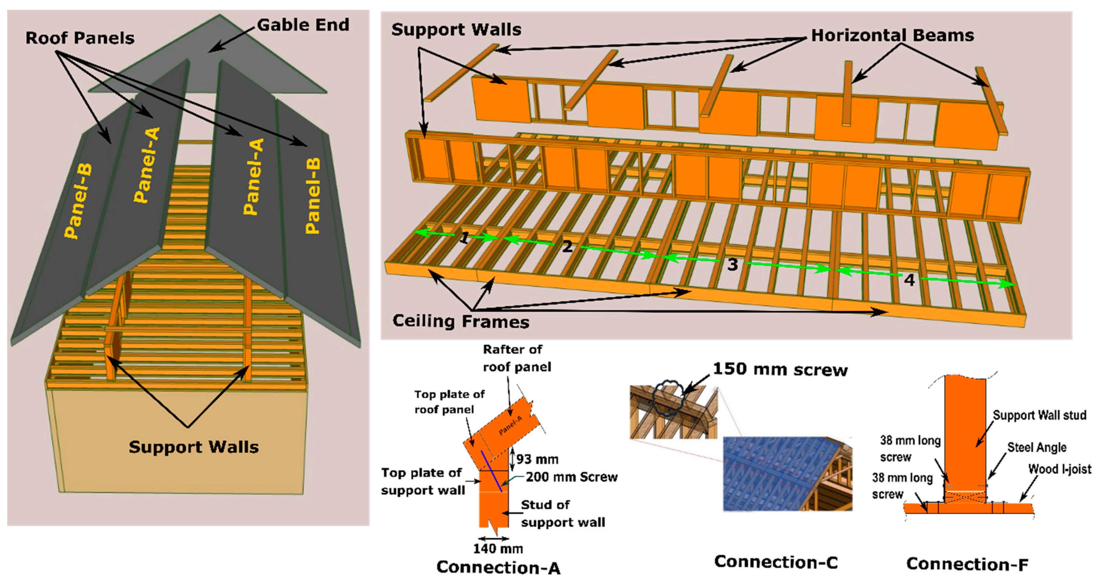
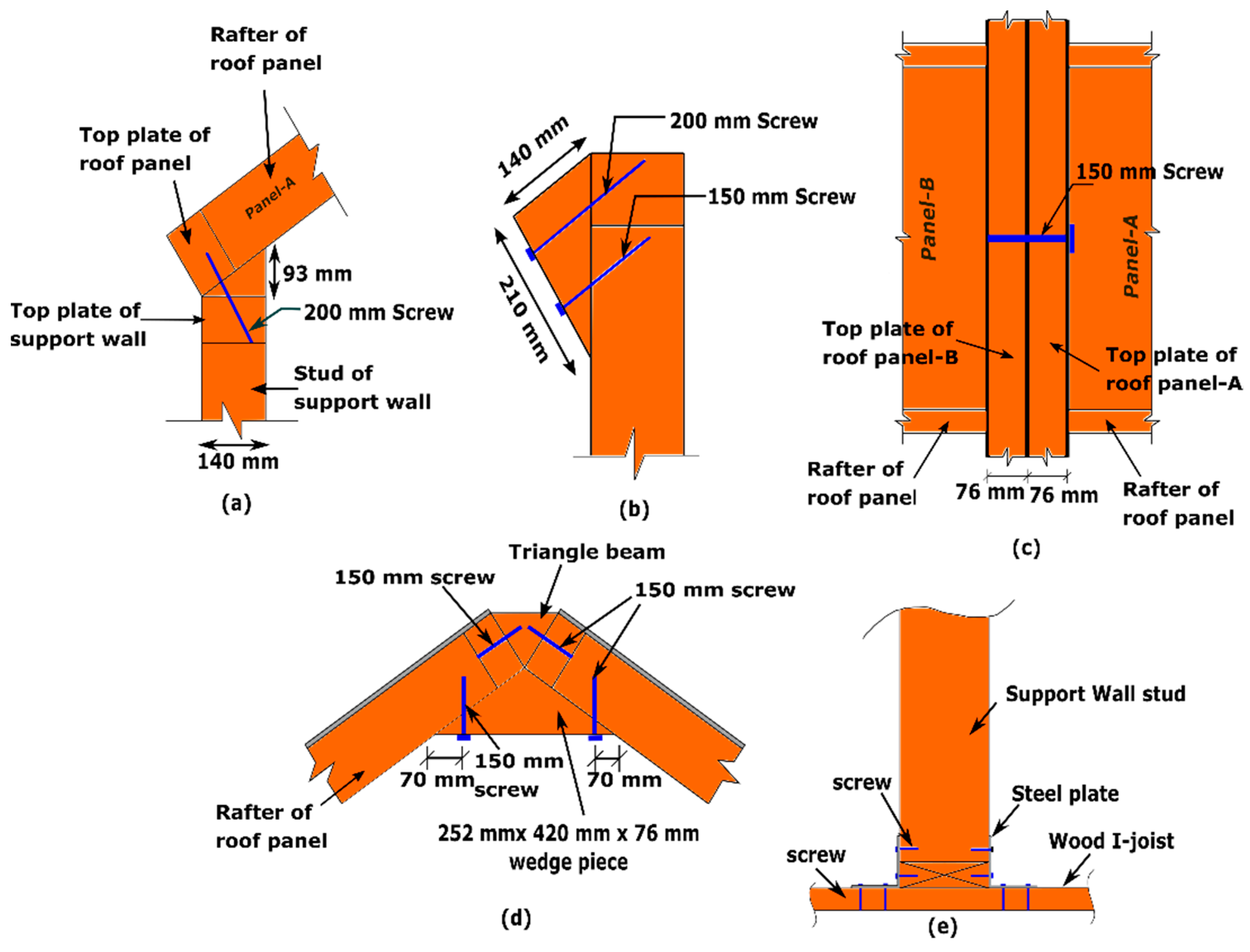
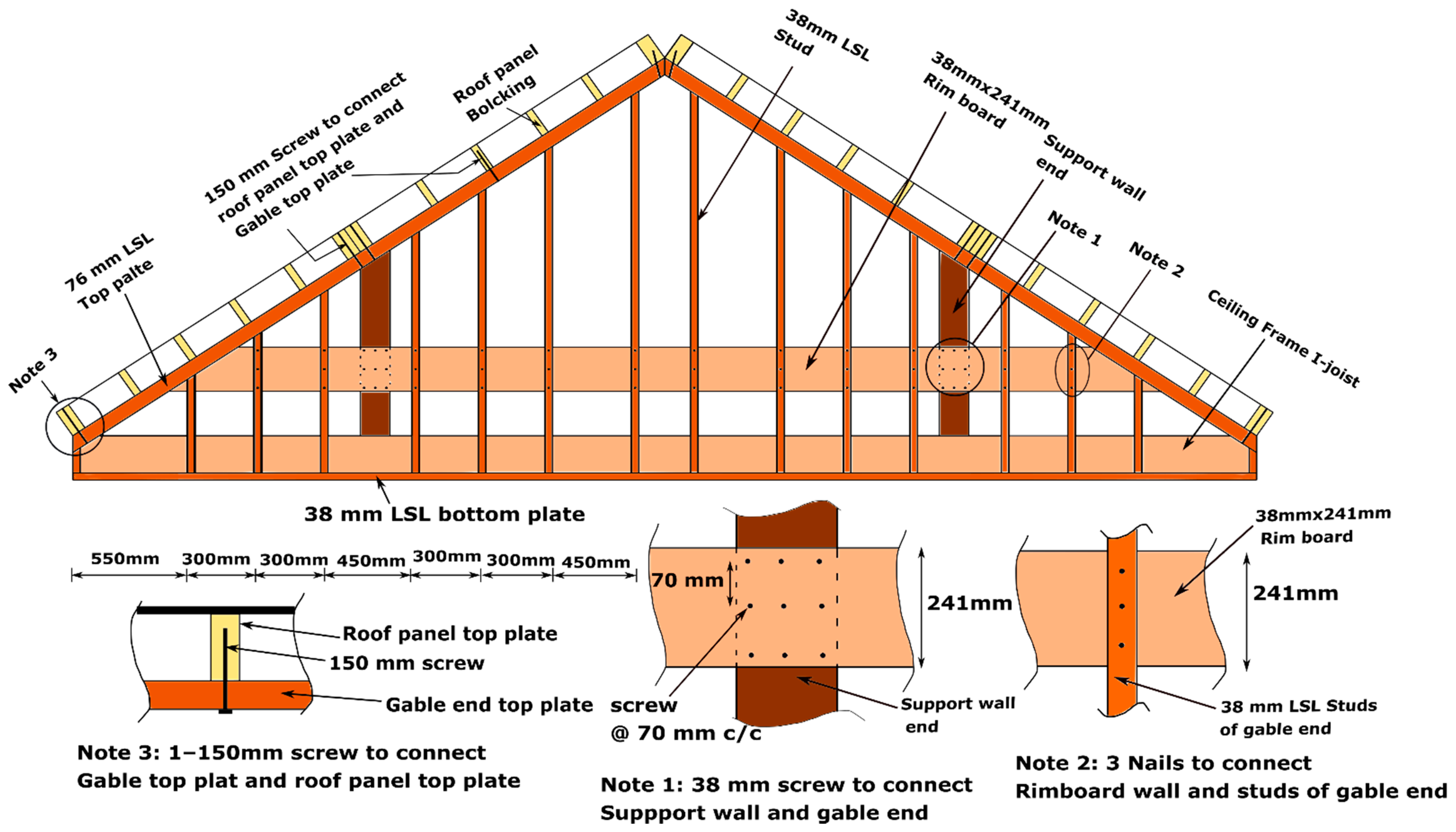
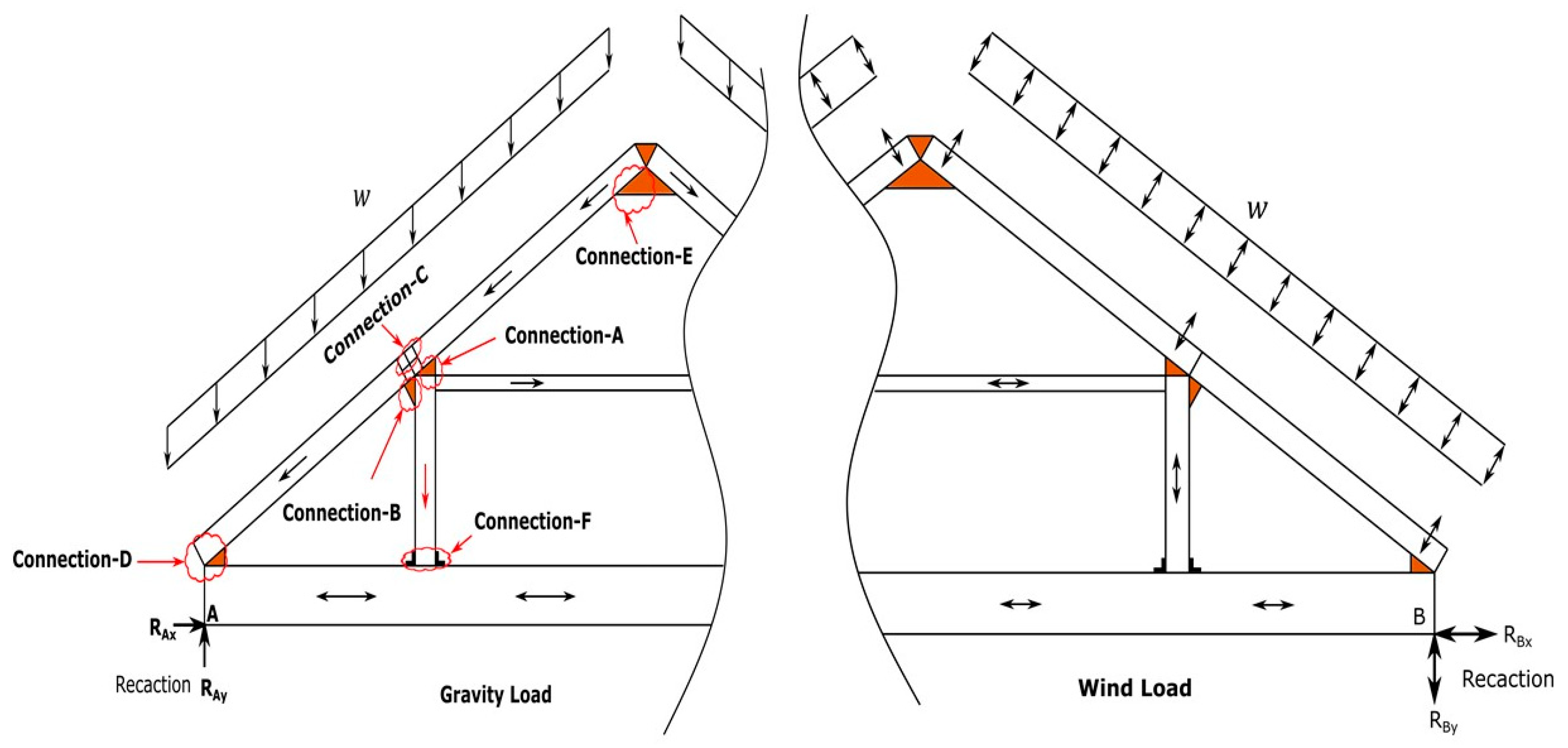
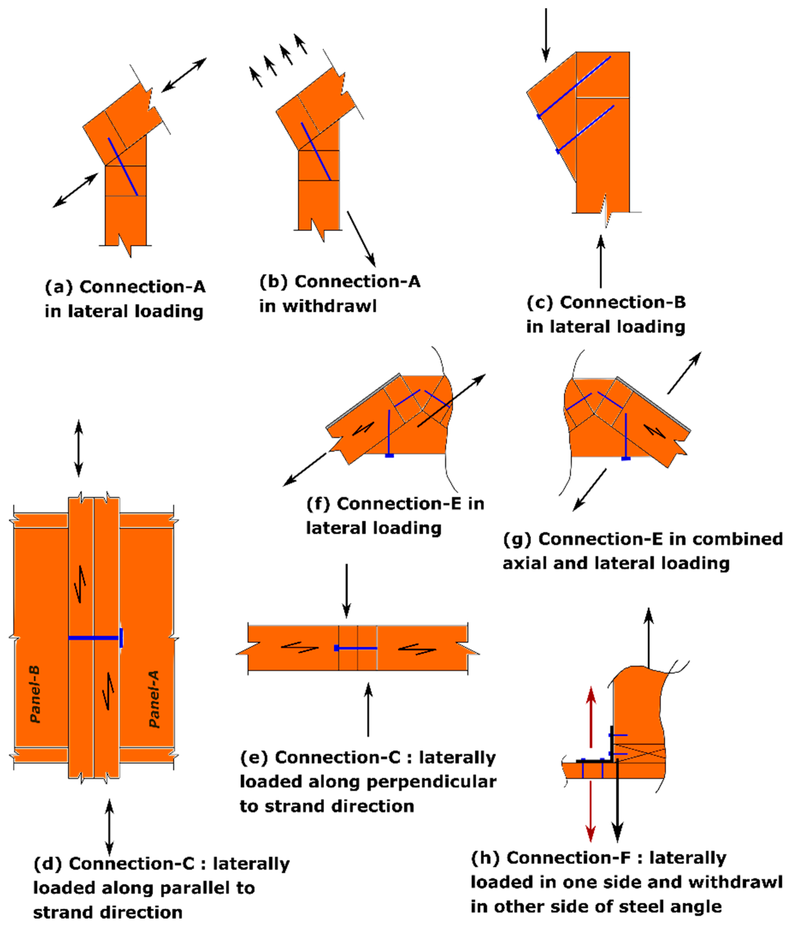
2. Development of Connection Details
3. Materials
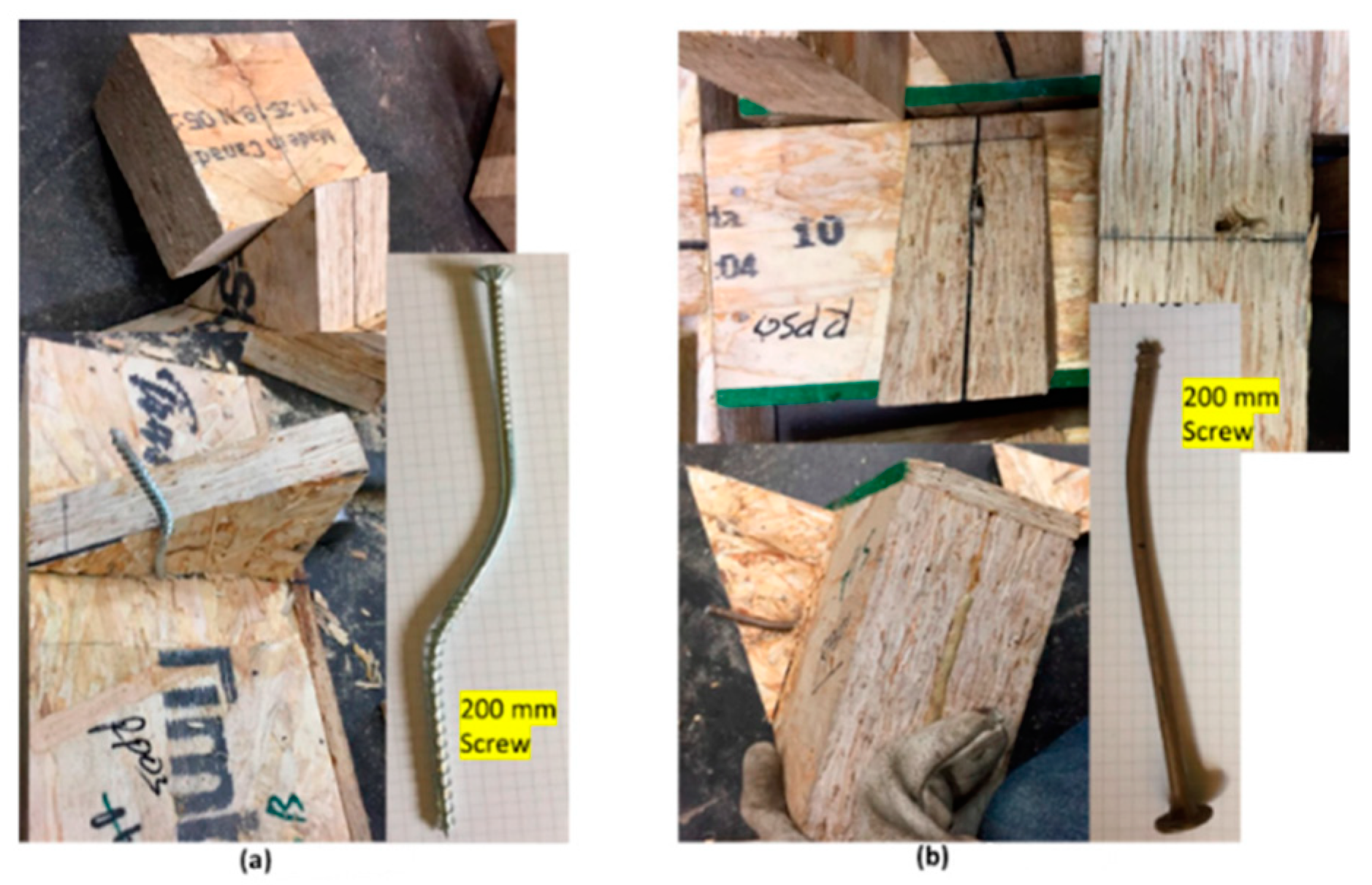
3.1. Screws
3.2. Timber Elements
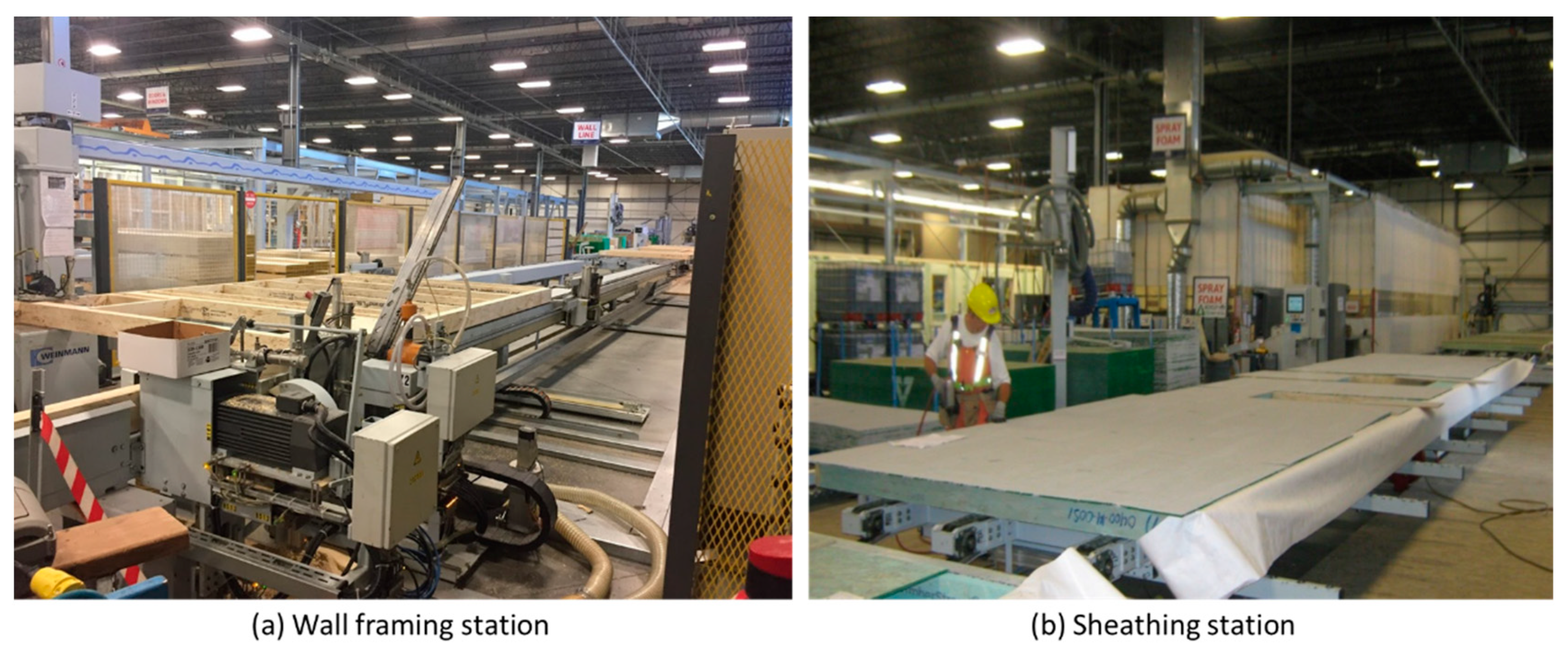
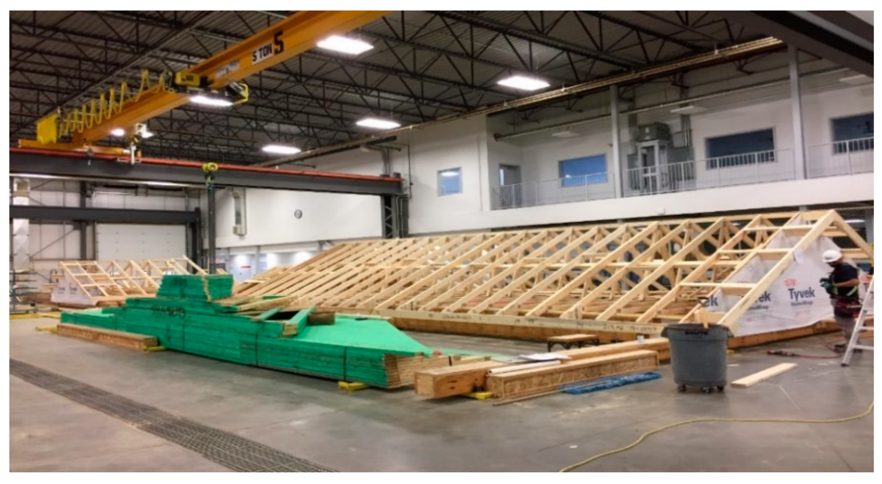
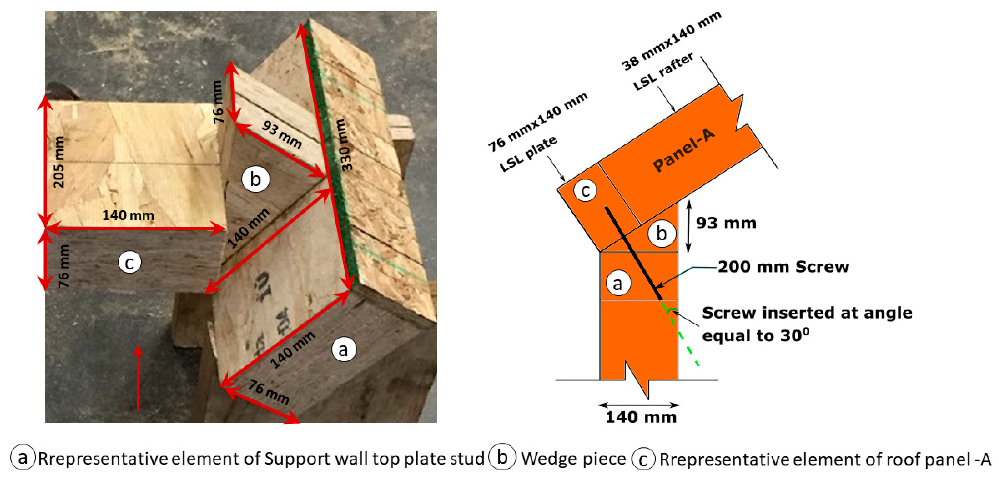
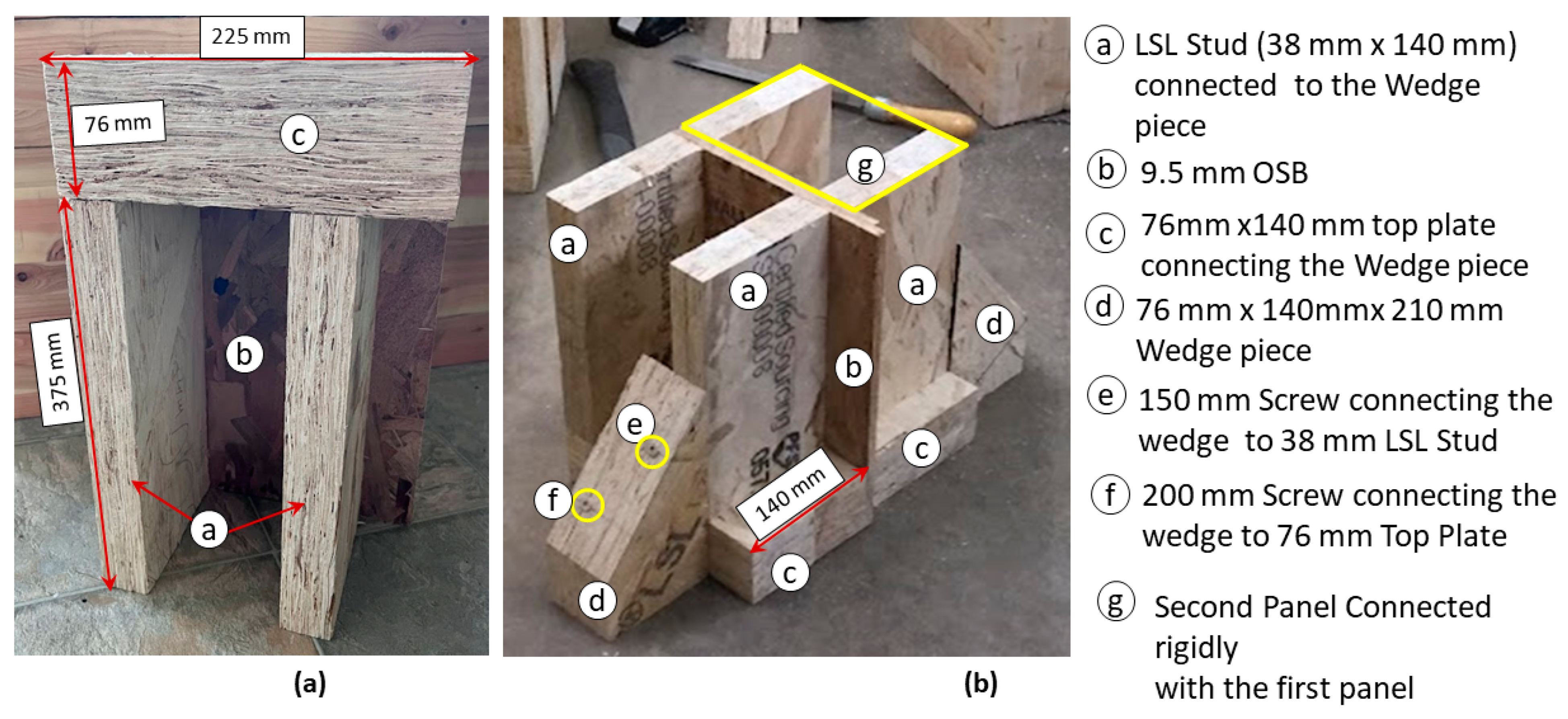
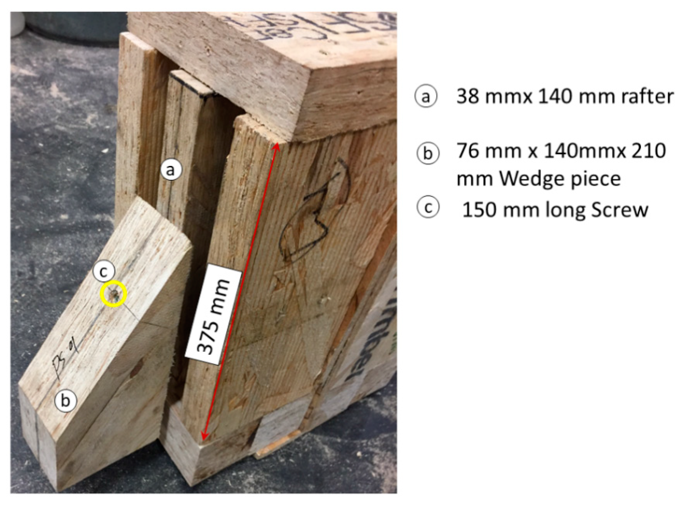
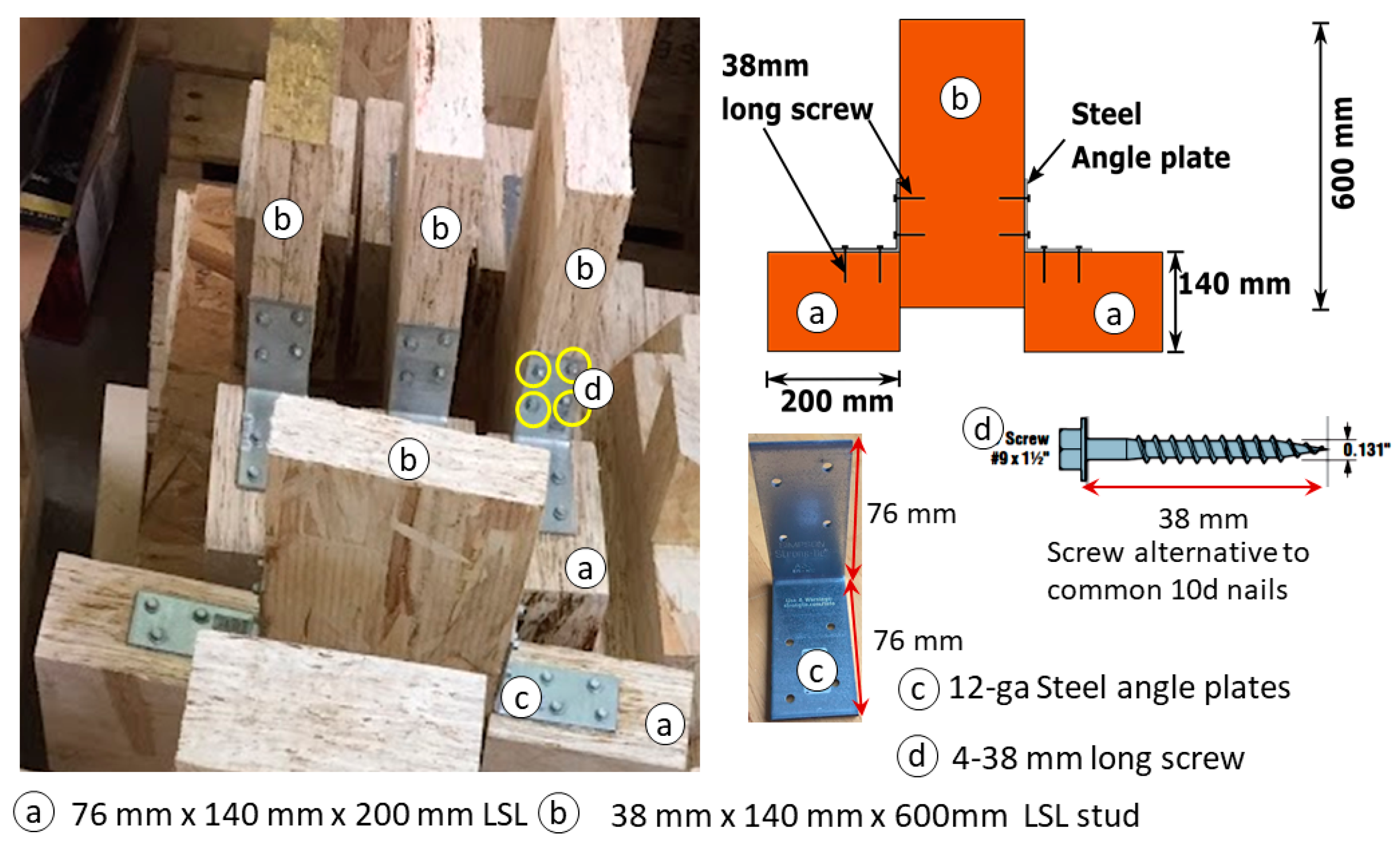
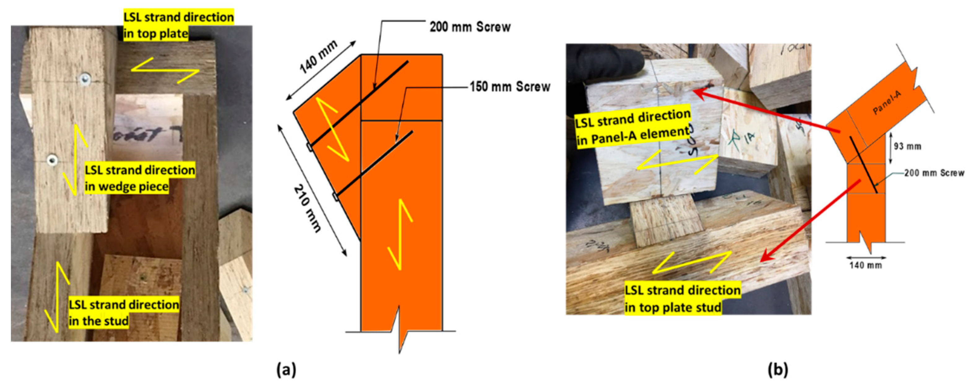
4. Fabrication of Connection Specimens
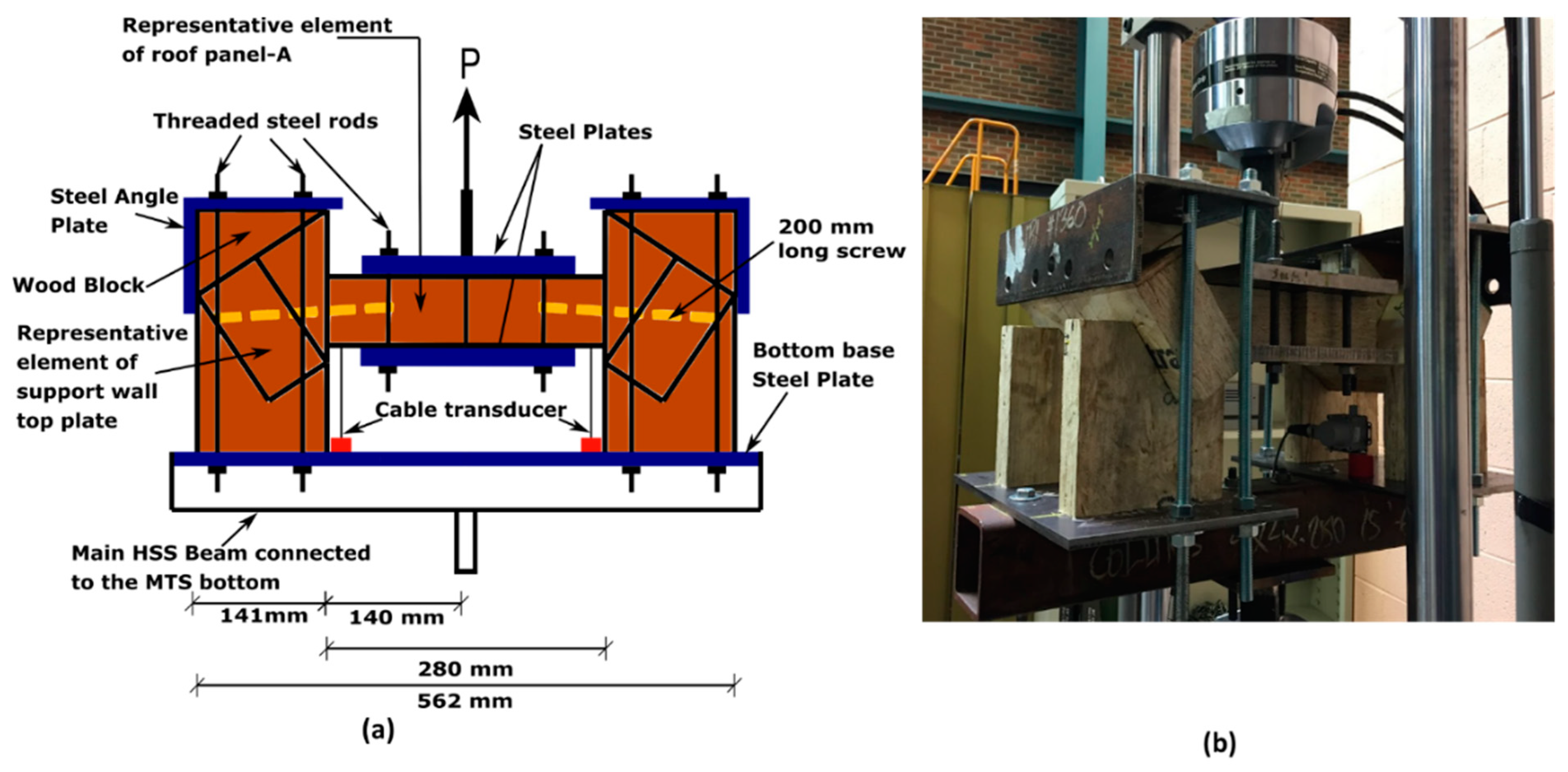
5. Test Setup
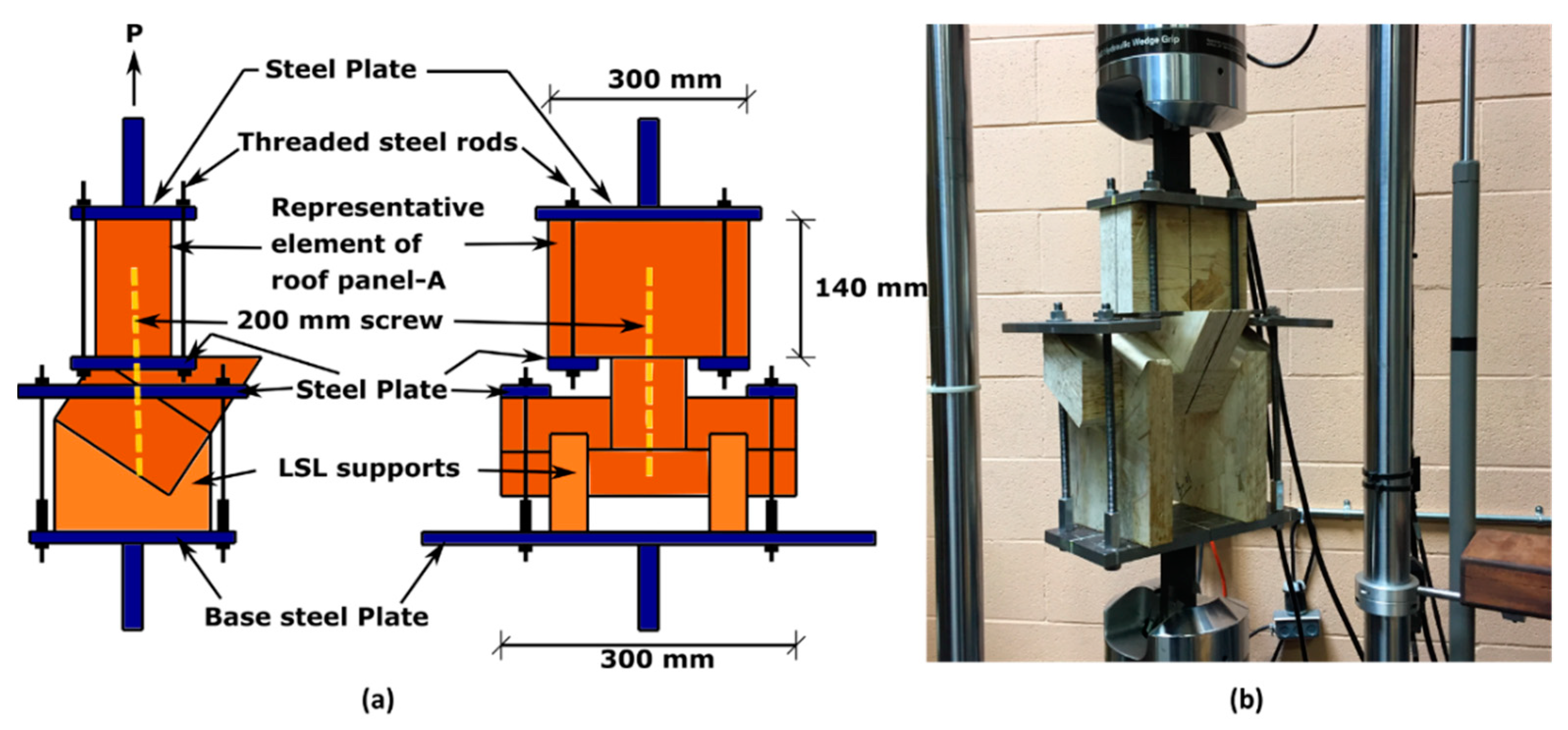
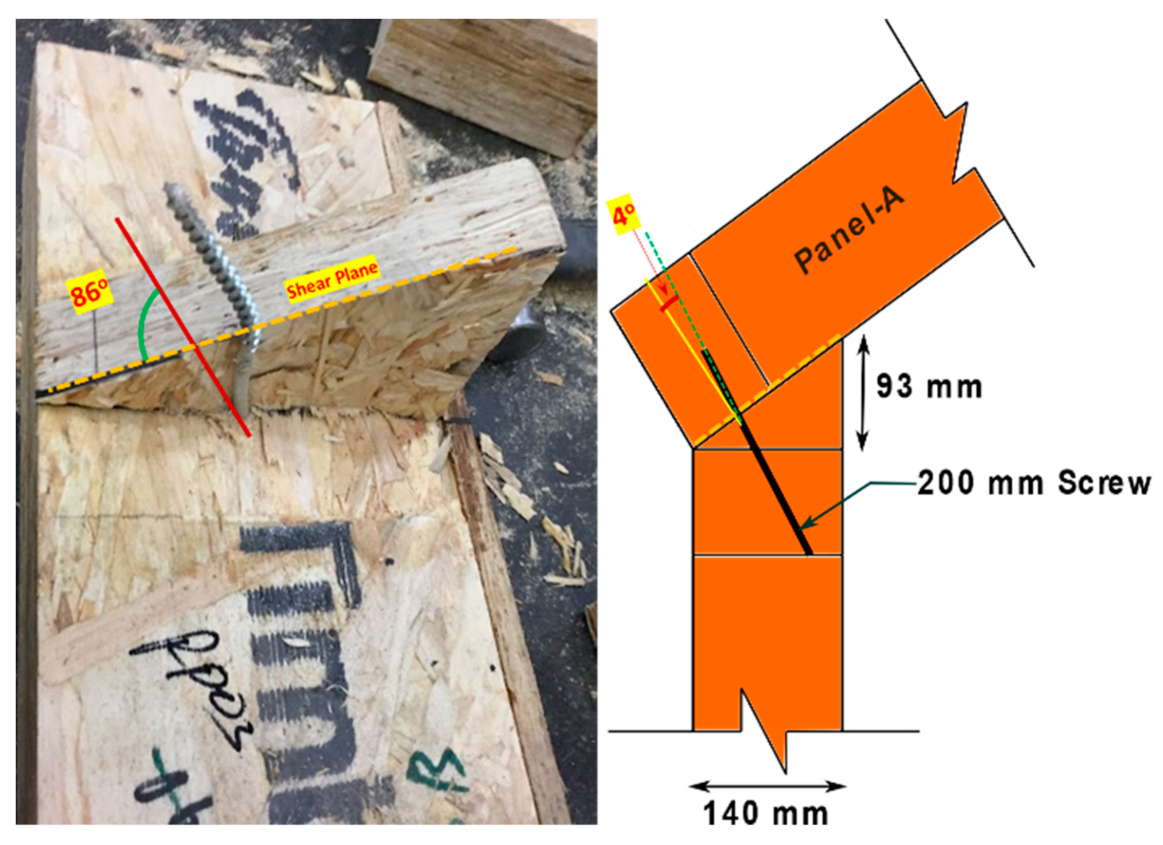
5.1. Connection-A Setup
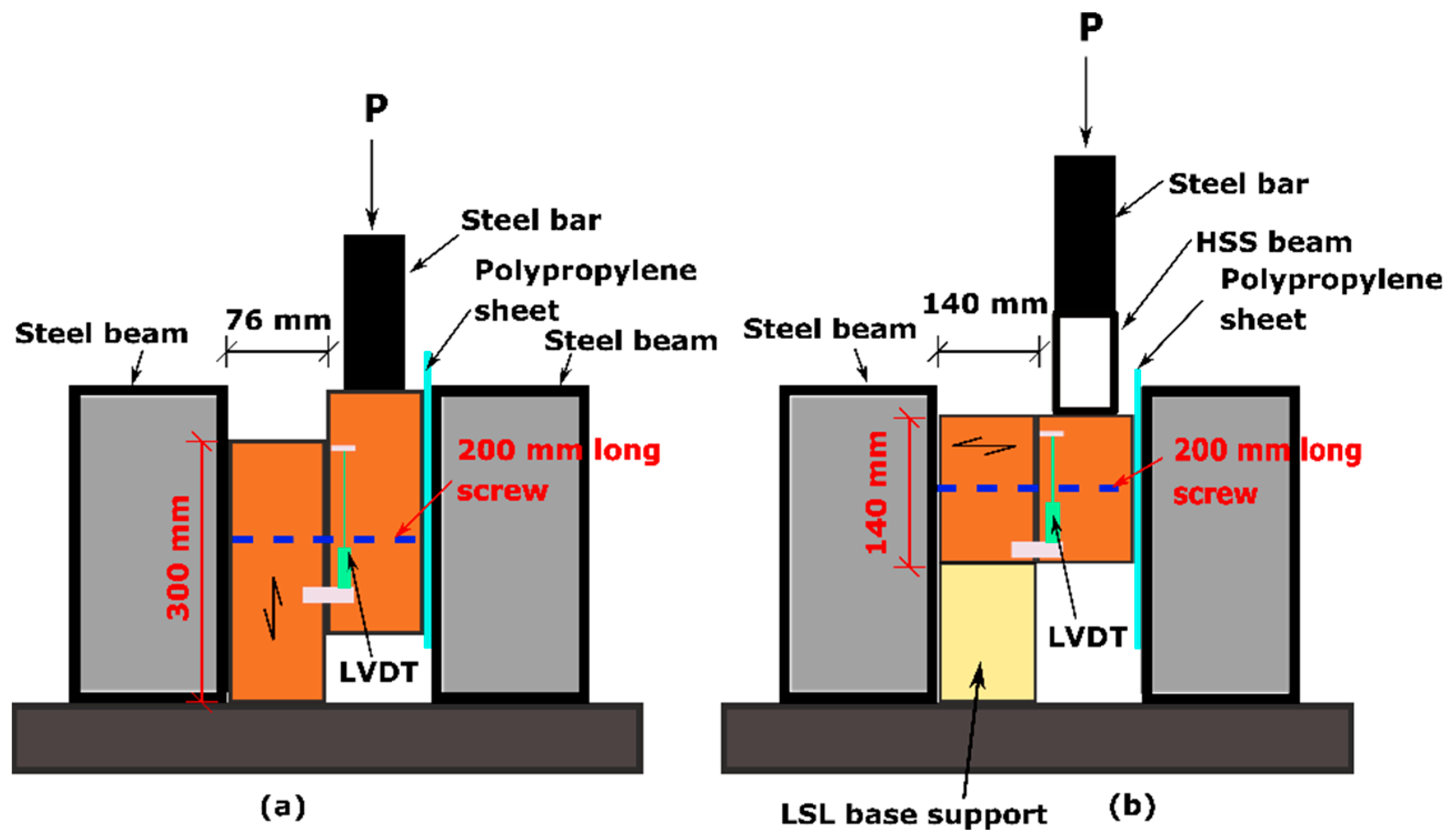
5.2. Connection-B and Connection-E Setup
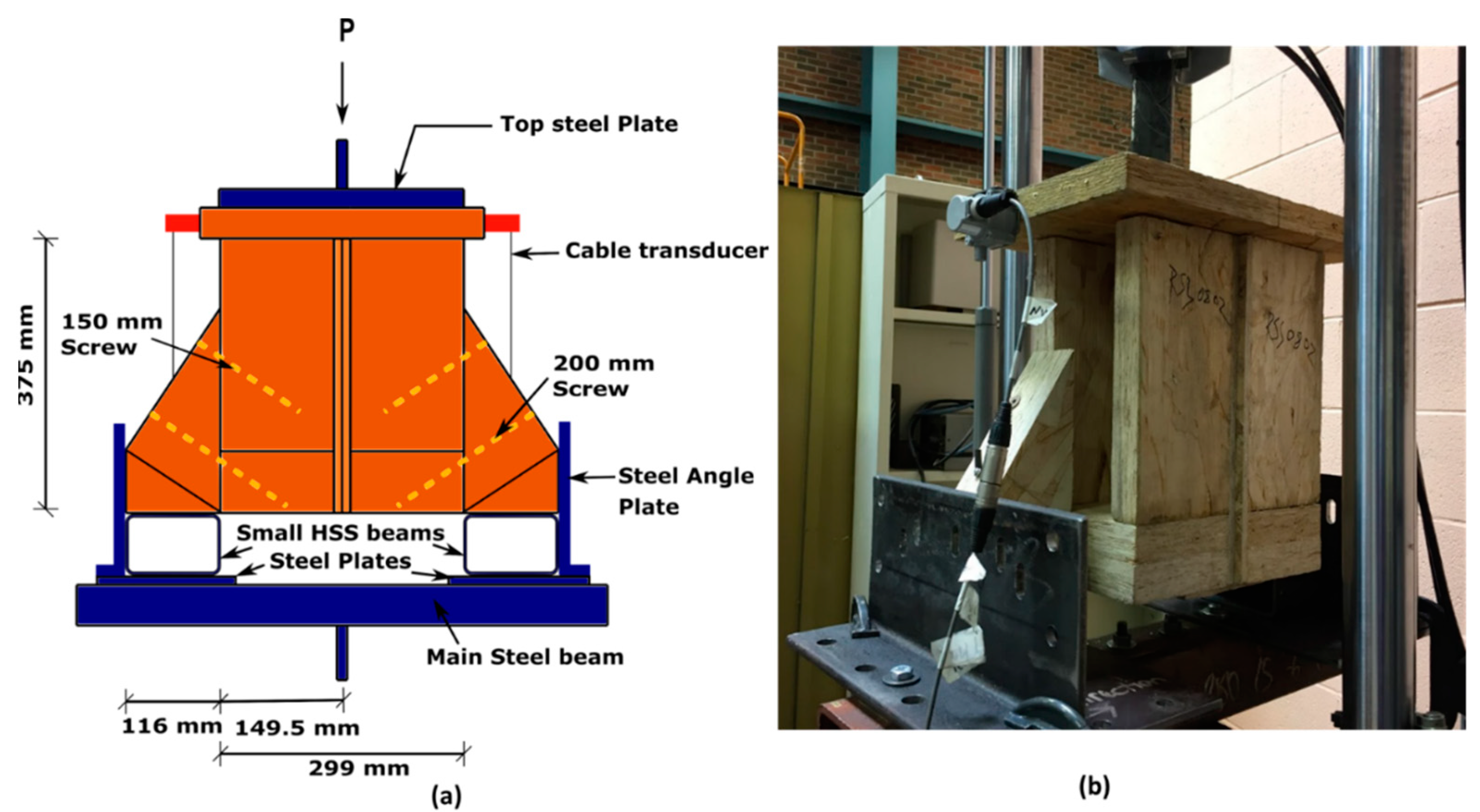
5.3. Connection-C Setup
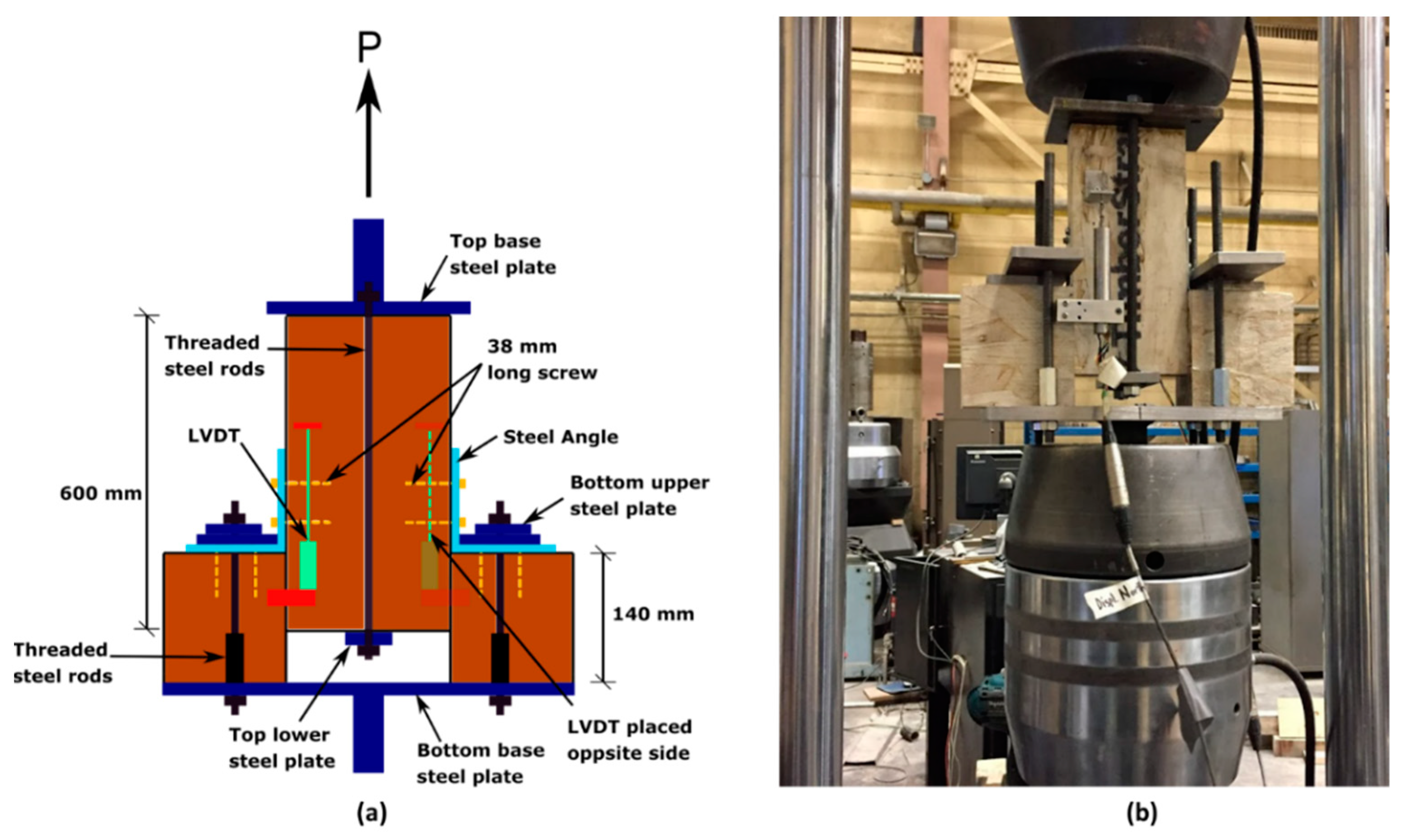
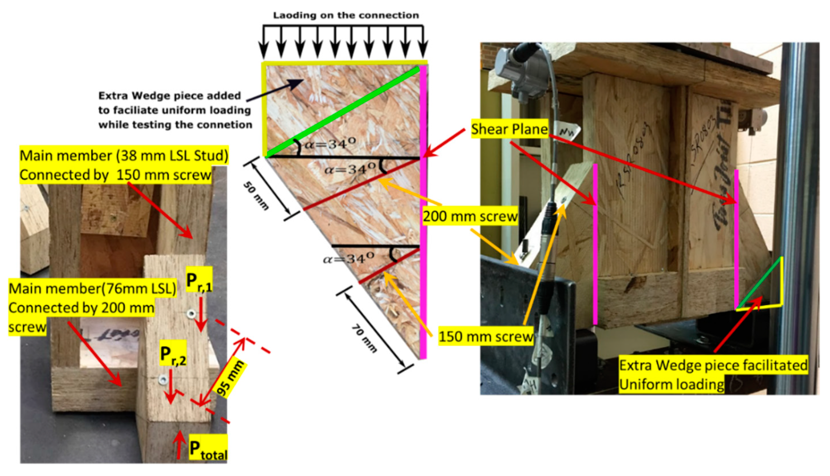
5.4. Connection-F Setup
6. Assessment of Connection Mechanical Parameters
7. Results
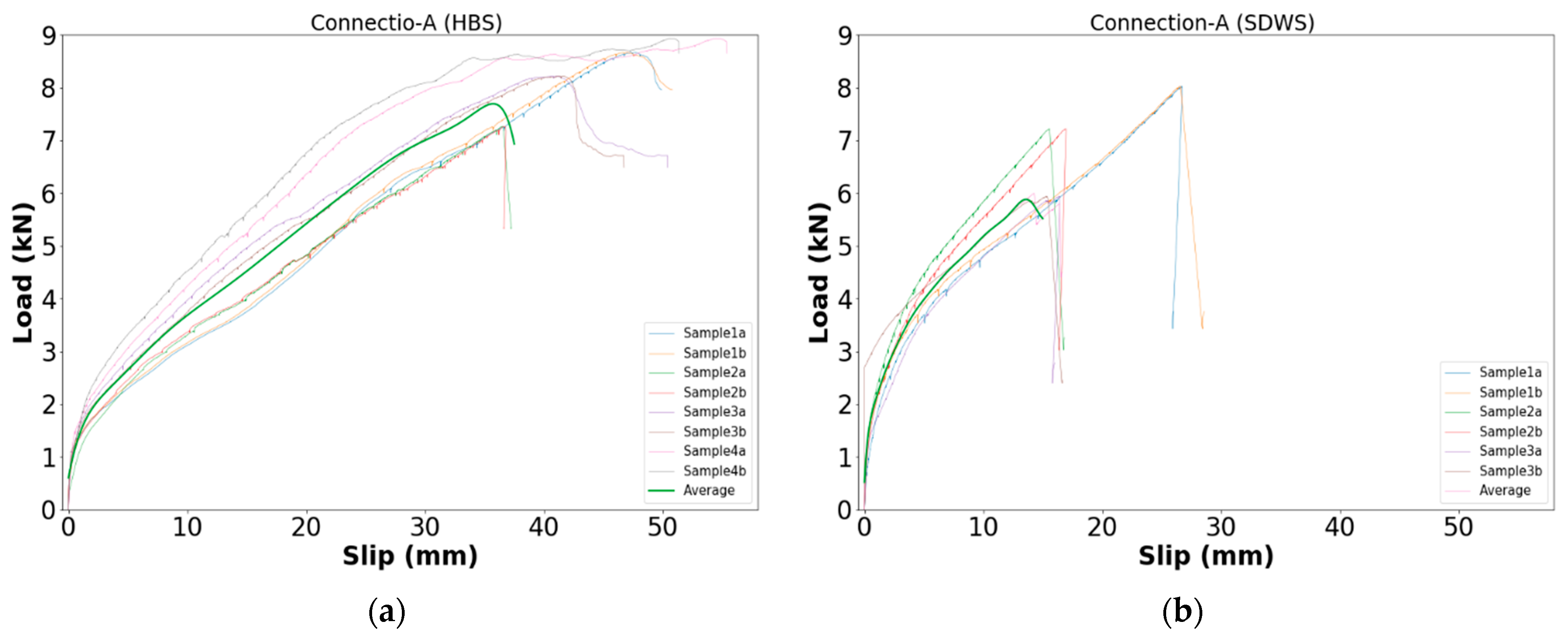
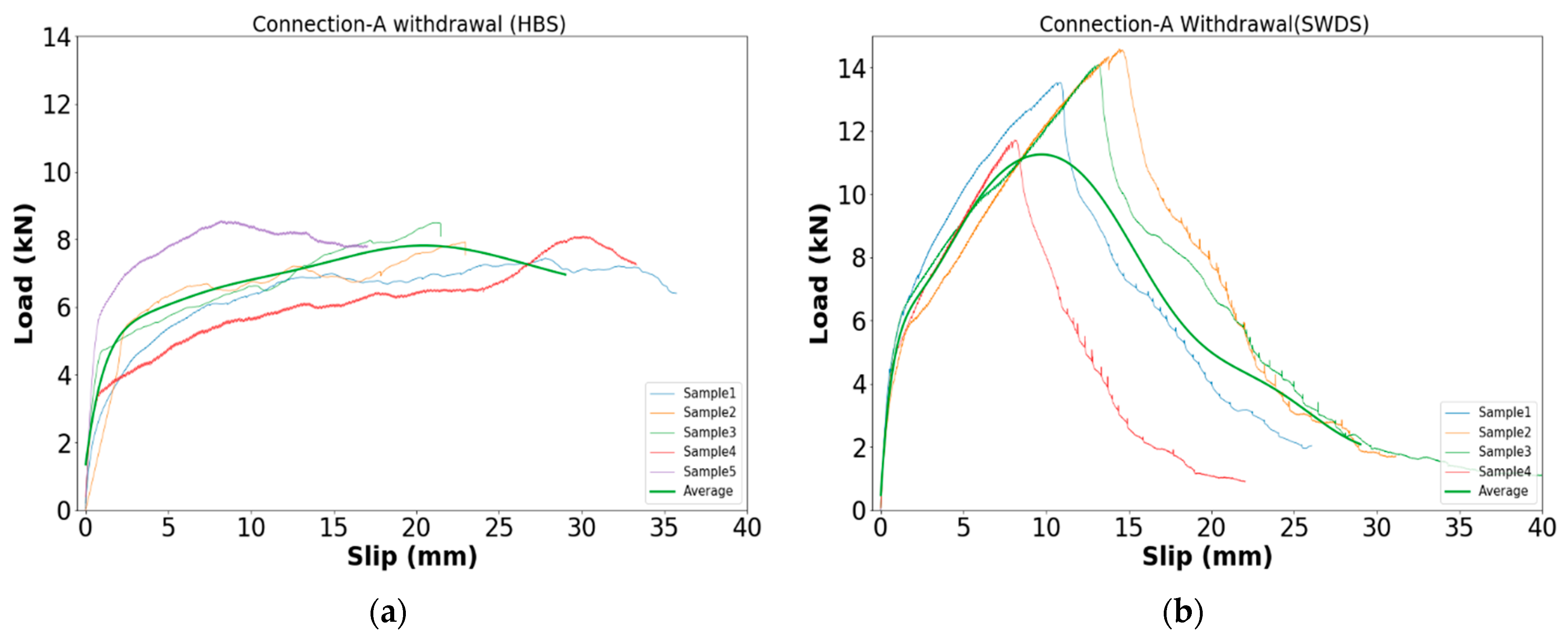
7.1. Connection-A Results
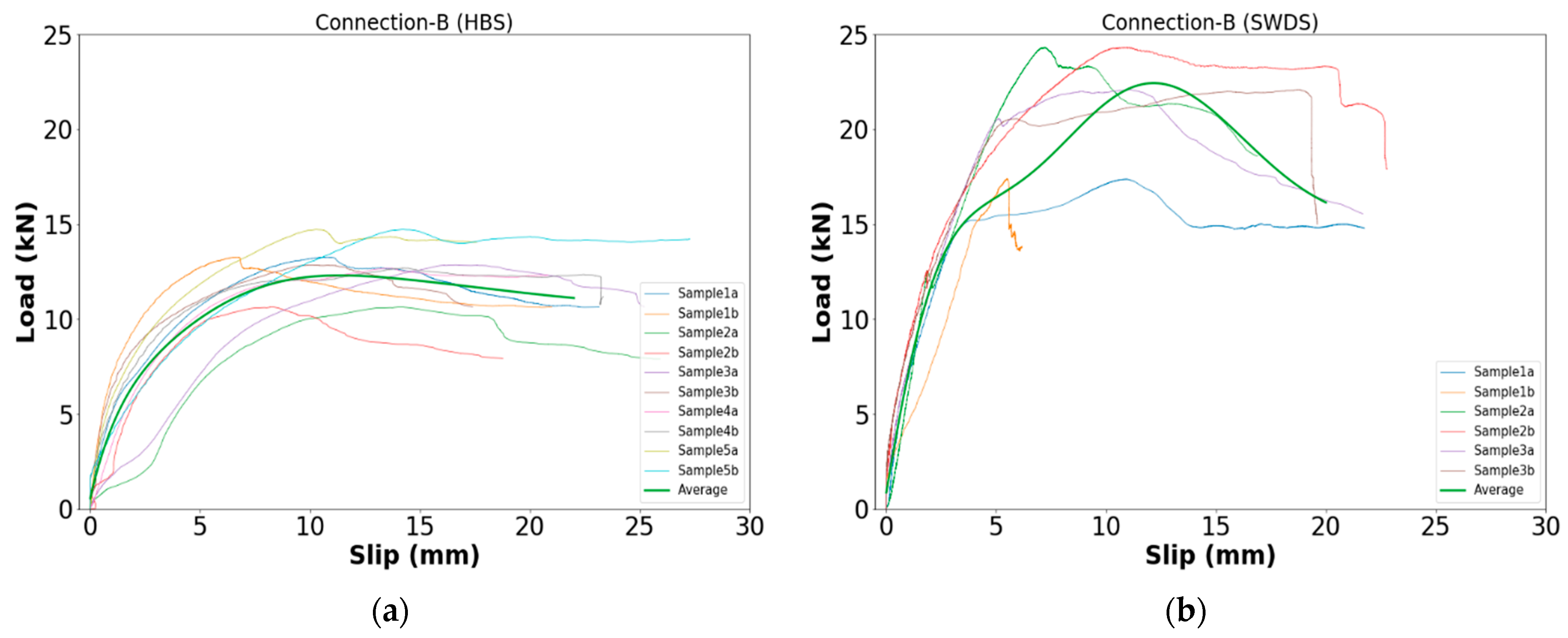
7.2. Connection-B Results
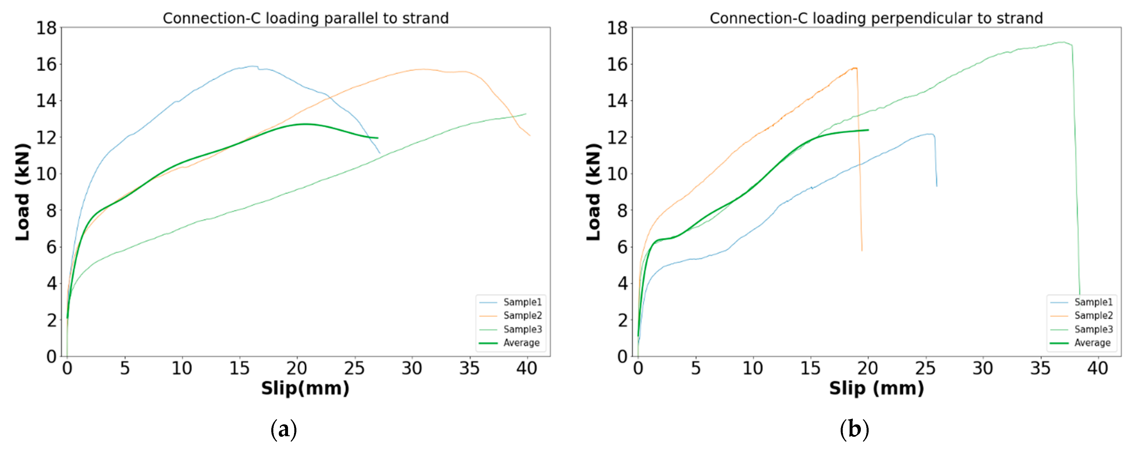
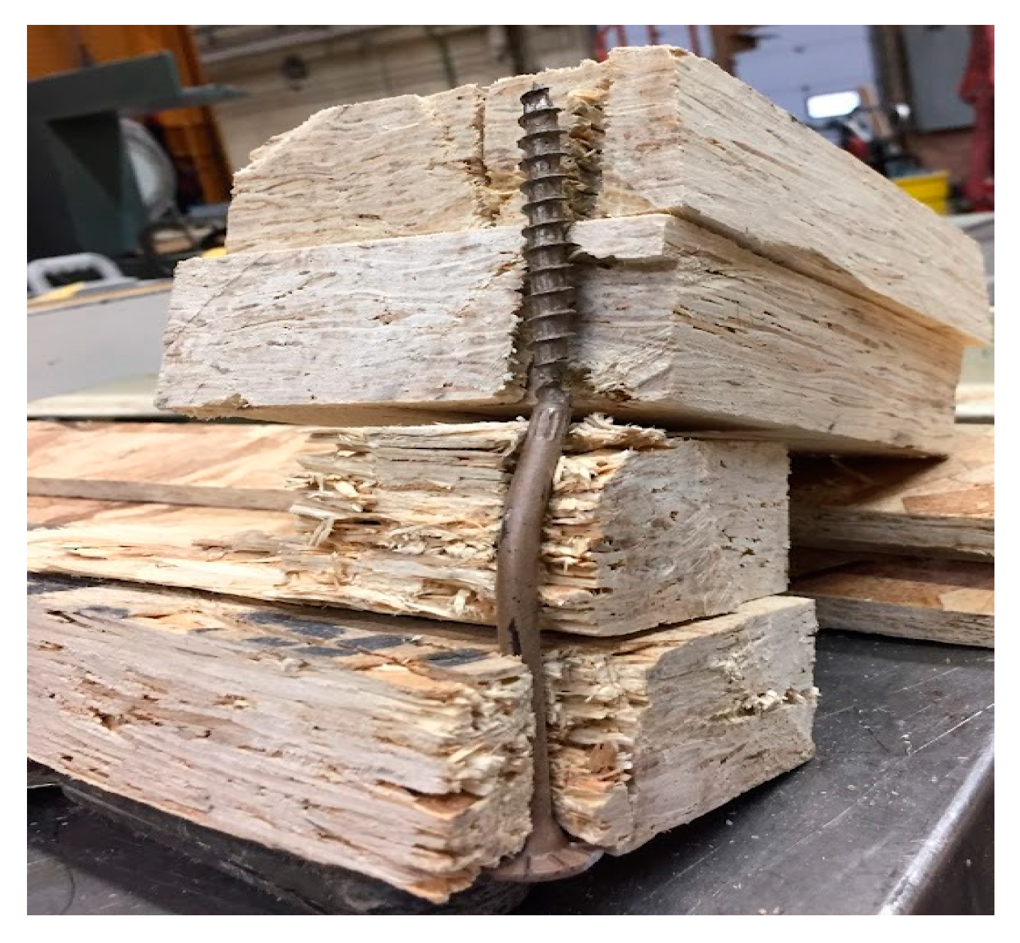
7.3. Connection-C Results
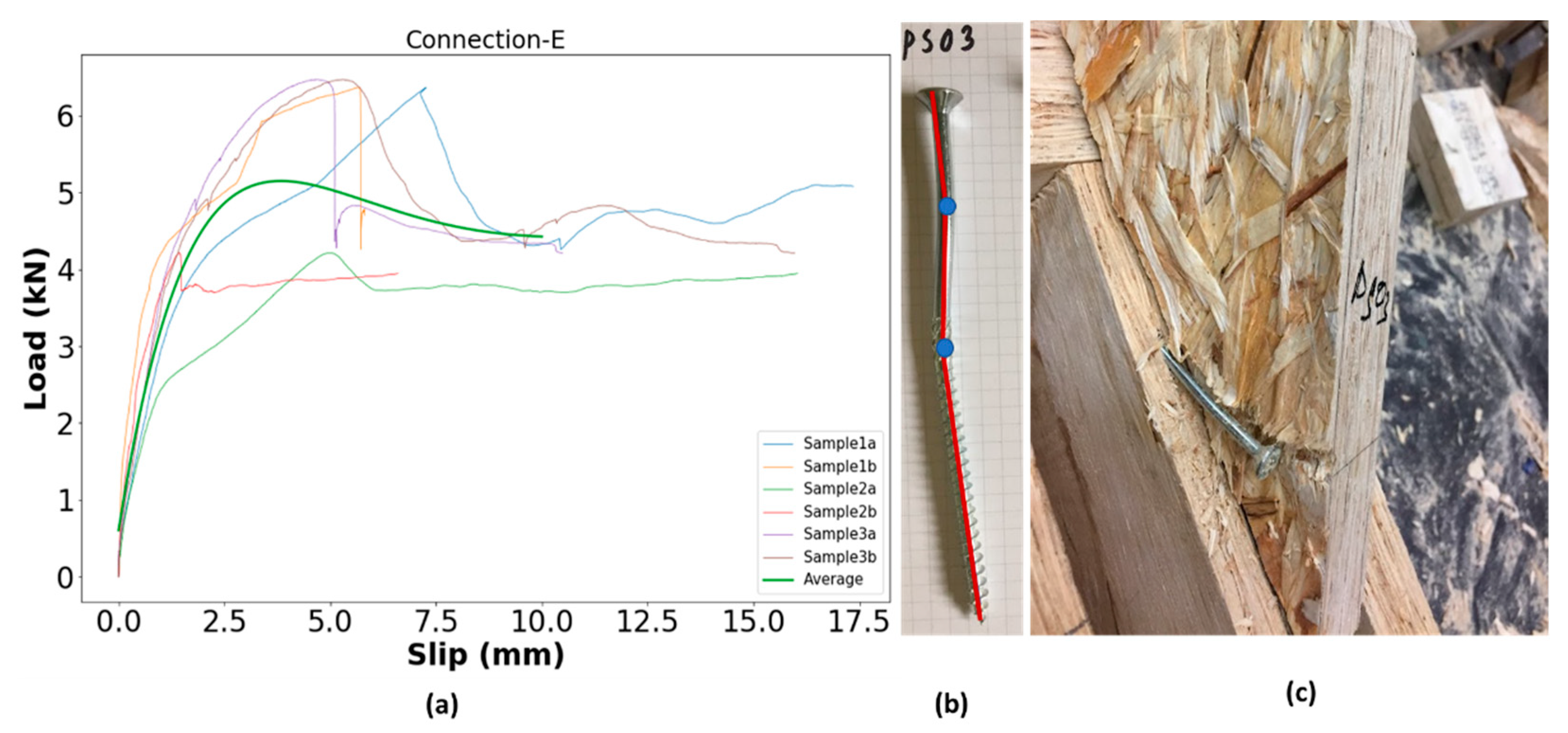
7.4. Connection-E Results
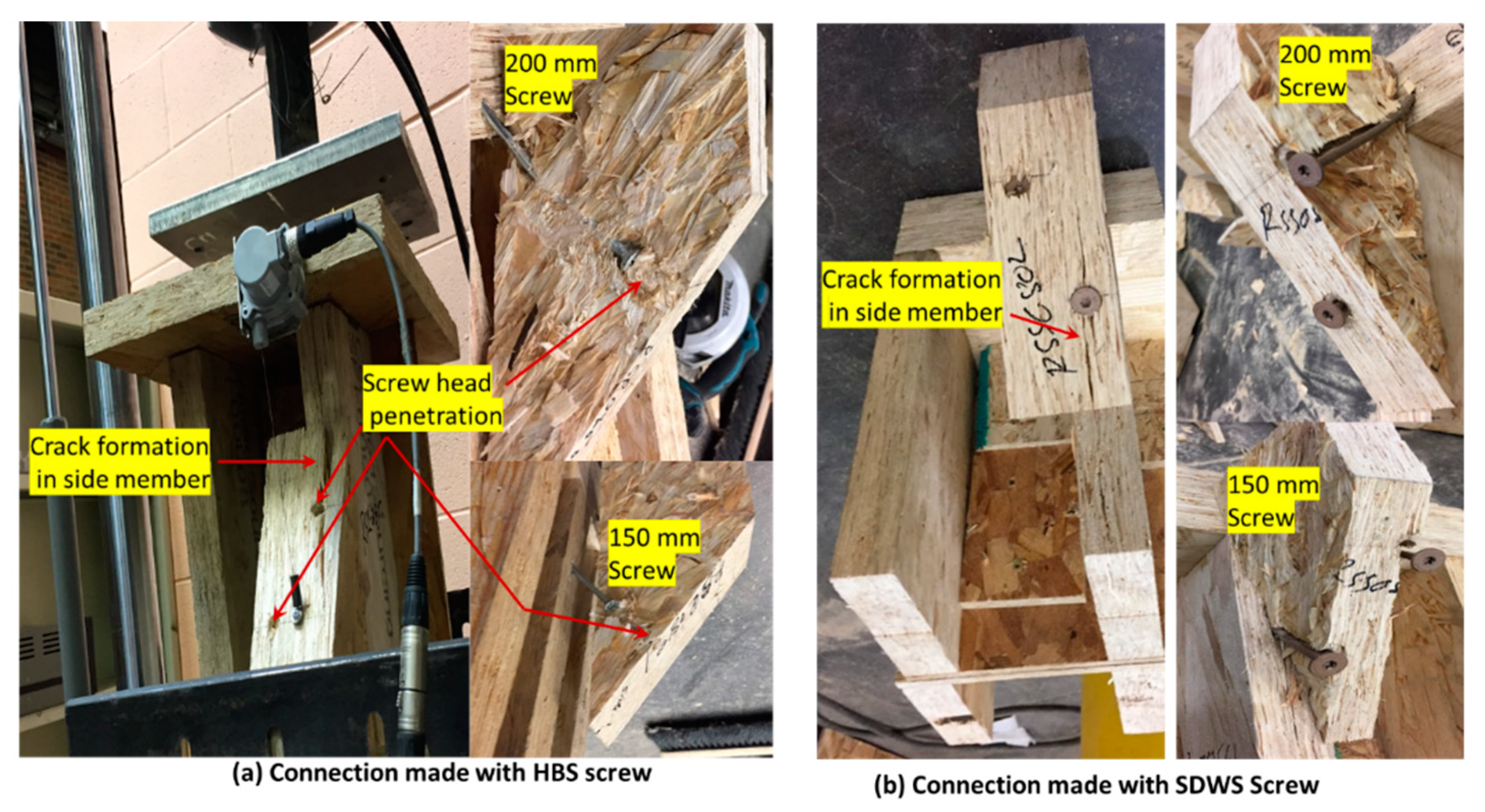
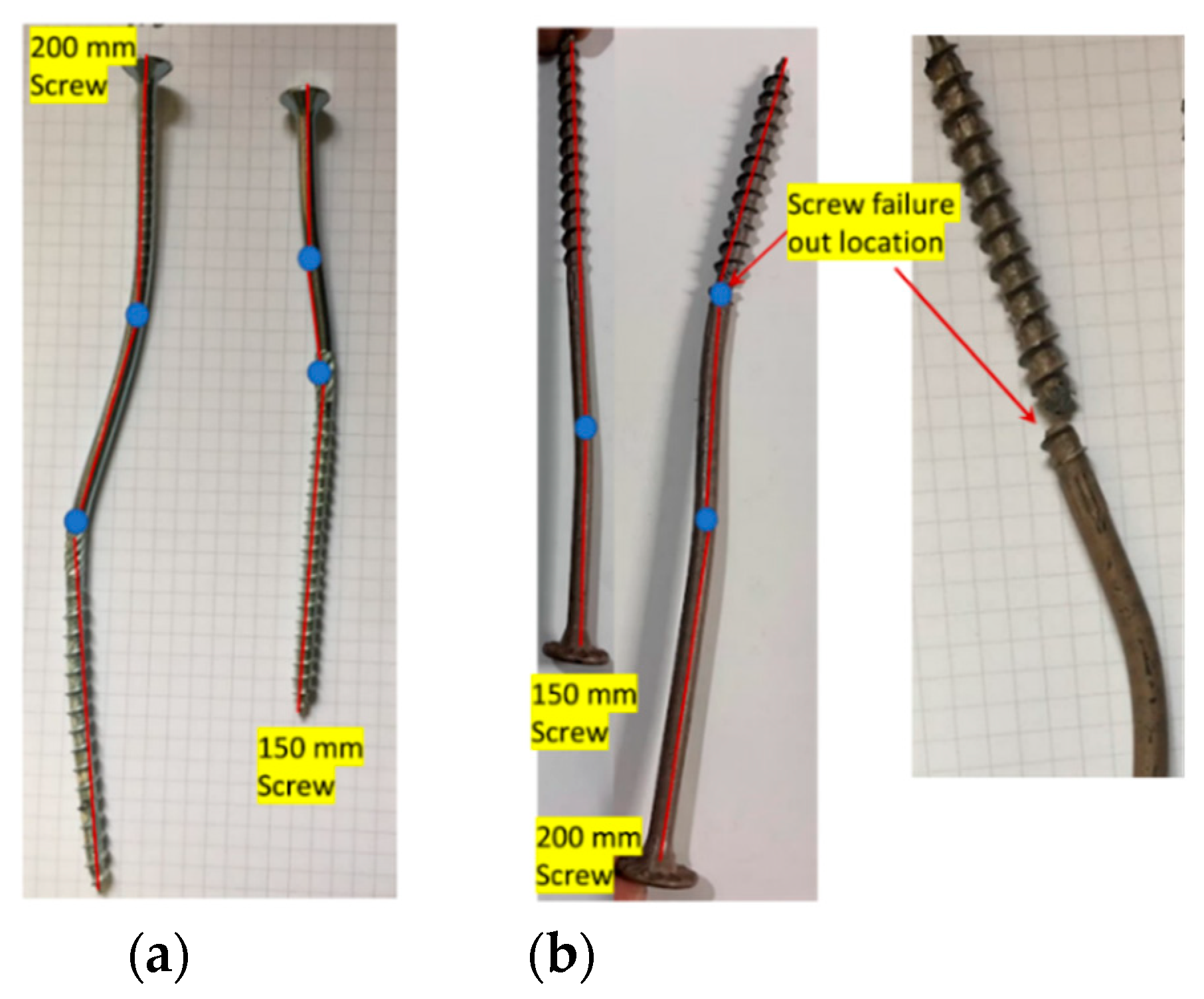
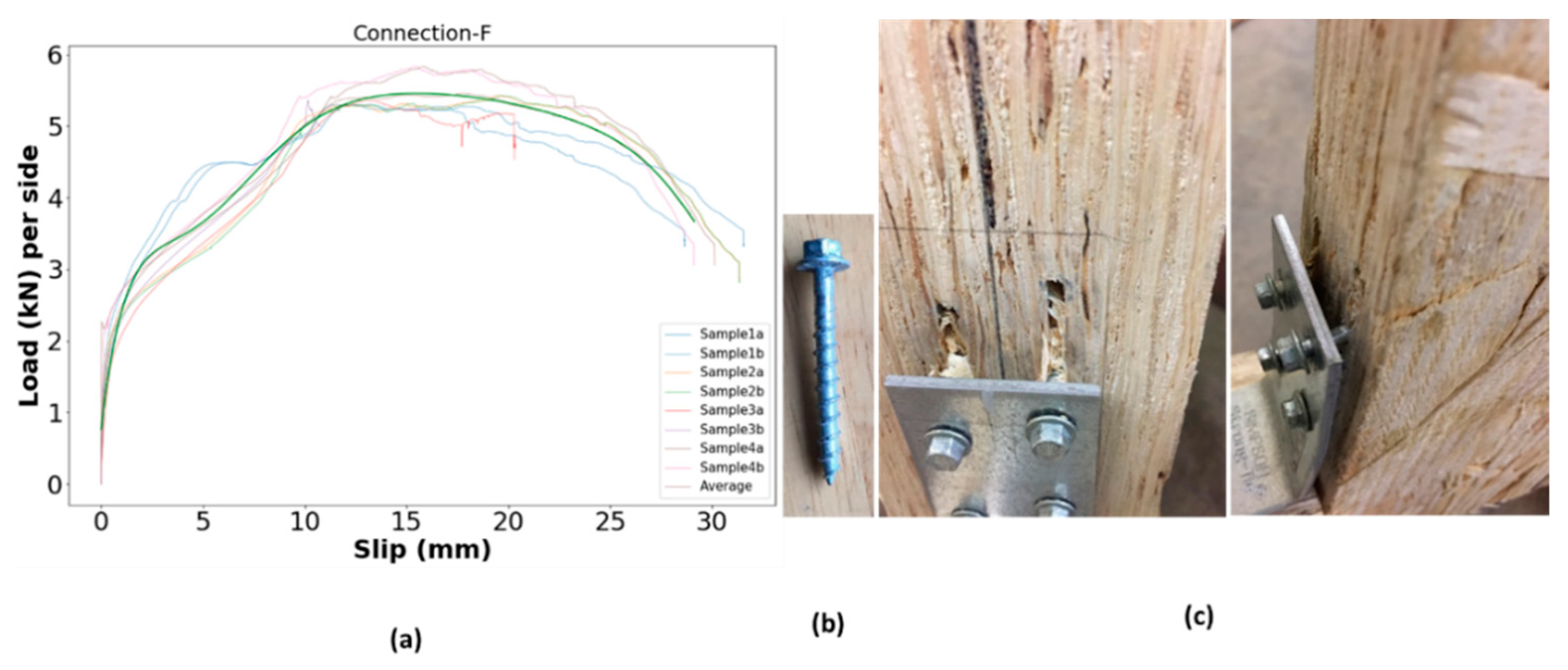
7.5. Connection-F Results
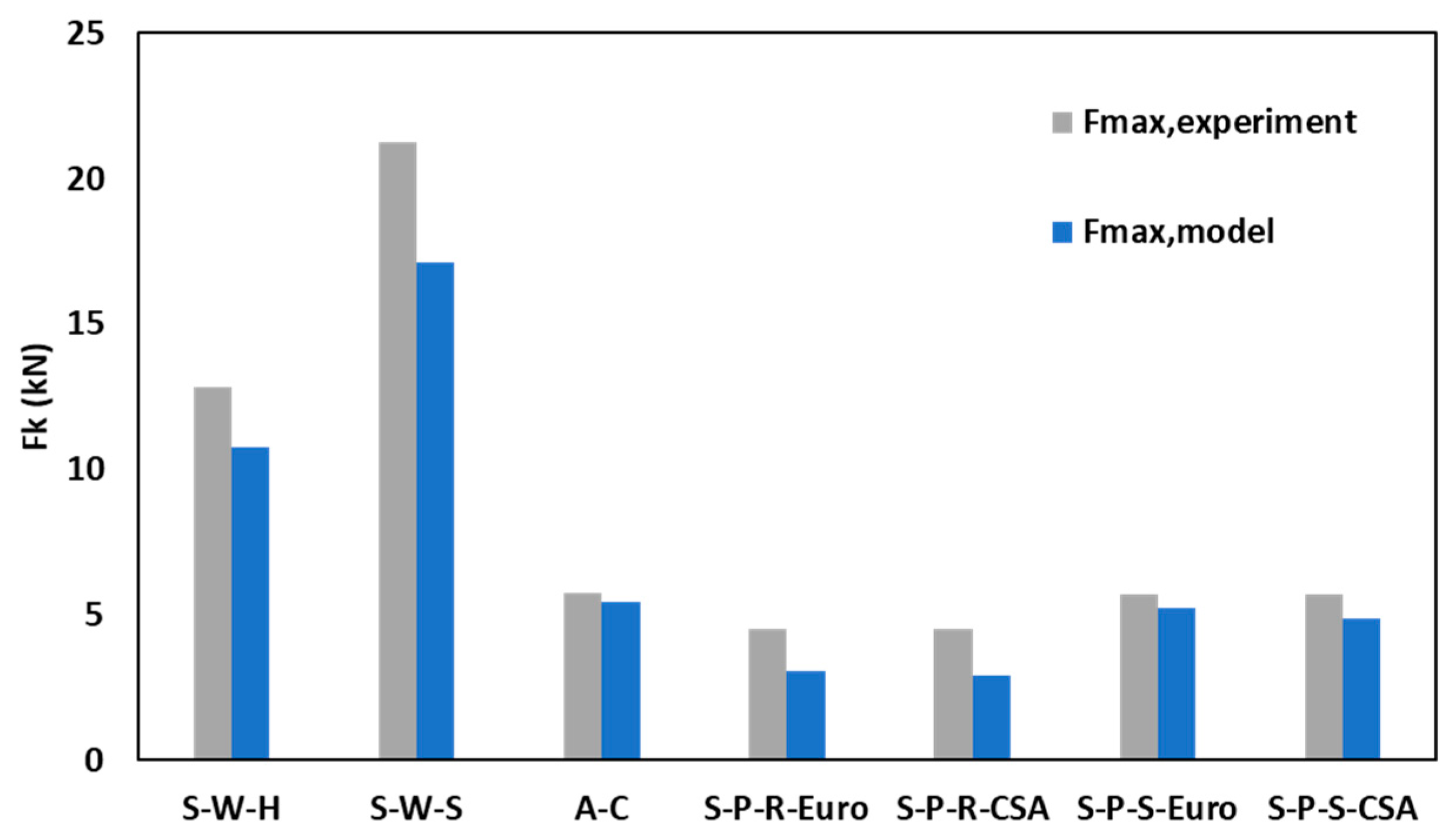
8. Comparison between Experimental Results and Theoretical Models
- ▪
- is the load carrying capacity of timber-to-timber connection with inclined screw.
- ▪
- is the withdrawal capacity of the screw.
- ▪
- s1 is the anchorage length of the screw into the first wood element measured orthogonally to the shear plane.
- ▪
- s2 is the anchorage length of the screw into the second wood element measured orthogonally to the shear plane.
- ▪
- is the embedment strength of the head side wood member.
- ▪
- is the embedment strength of the point side wood member.
- ▪
- the ratio of embedment strengths.
- ▪
- is the withdrawal strength of the screw from the head side wood member.
- ▪
- is the withdrawal strength of the screw from the point side wood member.
- ▪
- d is the effective diameter of the screw.
- ▪
- My is the yield moment of the screw.
- ▪
- μ is the friction coefficient at the interface between wood elements (0.25 for wood to wood).
9. Conclusions
Author Contributions
Funding
Institutional Review Board Statement
Informed Consent Statement
Data Availability Statement
Acknowledgments
Conflicts of Interest
References
- Koo, K.; Lafond, C.; Abasian, F. Industrialized Construction Program Machining Optimization: Equipment and Software Suppliers. Available online: https://library.fpinnovations.ca/fr/permalink/fpipub53064 (accessed on 1 November 2021).
- ACQBUILT Inc. Company Database and Personal Visits for Images. Available online: http://www.acqbuilt.com/ (accessed on 3 November 2019).
- Altaf, M.S. Integrated Production Planning and Control System for Prefabrication of Panelized Construction for Residential Building. Ph.D. Thesis, University of Alberta, Edmonton, AB, Canada, 2016. [Google Scholar]
- Brown, R. Production Improvements in Offsite Construction Facilities Using Simulation and Lean Principles. Master’s Thesis, University of Alberta, Edmonton, AB, Canada, 2020. [Google Scholar]
- Islam, M.S.; Chui, Y.H.; Al-Hussein, M.; Altaf, M. A New Panelized Roof Design Approach for Offsite Fabrication of Light-Frame Wood Residential Construction Projects. In Proceedings of the Canadian Society of Civil Engineering Annual Conference 2021, Winnipeg, MB, Canada, 9–12 June 2010; CSCE 2021; Lecture Notes in Civil Engineering. Springer: Singapore; Volume 244. [Google Scholar] [CrossRef]
- Islam, M.S.; Chui, Y.H.; Altaf, M.S. A Holistic Design Approach for Innovative Panelized Light-Wood Frame Roof Construction. In Proceedings of the WCTE 2021—World Conference on Timber Engineering, Santiago, Chile, 9–12 August 2021. [Google Scholar]
- CSA O86-19; Engineering Design in Wood. CSA Group: Mississauga, ON, Canada, 2019.
- Rothoblaas HBS SOFTWOOD Countersunk Screw with Under-Head Ribs. Available online: https://www.rothoblaas.com/products/fastening/screws/screws-carpentry (accessed on 3 November 2021).
- Simpson Strong-Tie Strong-Drive® SDWS TIMBER Screw (Exterior Grade). Available online: https://www.strongtie.com/strongdrive_exteriorwoodscrews/sdws-db_screw/p/strong-drive-sdws-timber-screw-exterior-grade (accessed on 3 November 2021).
- ETA European Technical Assessment ETA-11/0030-Rotho Blaas Self-Tapping Screws and Threaded Rods 2019. Product evaluation Report from Rothoblaas Company. Available online: https://www.rothoblaas.com/ftp/ETA_11_0030_RB_screws_2019.pdf (accessed on 14 June 2022).
- Uniform Evaluation Service (UES) Report 192: Evaluation Subjects Simpson Strong-Tie Strong Drive, SDW, SDWS, SDWH, and SDWV Screws. Available online: https://ssttoolbox.widen.net/view/pdf/96lrxjfxjn/IAPMO_UES_ER192.pdf?t.download=true&u=cjmyin (accessed on 3 November 2021).
- Simpson Strong-Tie Company Inc. Evaluation Report Number: 192 Evaluation SUBJECT: SIMPSON STRONG-DRIVE® SDW22, SDWS22DB, SDWH19DB, SDWS22, SDWS19, SDWH27G, and SDWS16 WOOD SCREWS; 2019; Available online: https://ssttoolbox.widen.net/view/pdf/96lrxjfxjn/IAPMO_UES_ER192.pdf?t.download=true&u=cjmyin (accessed on 14 June 2022).
- Weyerhaeuser TJ-9500 Specifier’s Guide. Available online: https://www.weyerhaeuser.com/woodproducts/document-library/document_library_detail/tj-9500/ (accessed on 1 November 2019).
- Lam, F. Modern Structural Wood Products. Prog. Struct. Eng. Mater. 2001, 3, 238–245. [Google Scholar] [CrossRef]
- Murty, B.; Smith, I.; Asiz, A. Wood and Engineered Wood Product Connections Using Small Steel Tube Fasteners: Applicability of European Yield Model. J. Mater. Civ. Eng. 2007, 19, 965–971. [Google Scholar] [CrossRef]
- CCMC Evaluation Report of Canadian Construction Materials Centre (CCMC). 12627-R Timber Strand LSL. Available online: https://www.weyerhaeuser.com/application/files/8715/6115/1801/12627-R.pdf (accessed on 1 September 2019).
- ASTM. Standard Test Methods for Mechanical Fasteners in Wood Designation: D1761-12; ASTM: West Conshohocken, PA, USA, 2012. [Google Scholar]
- European Committee for Standardization. EN 26891: Timber Structures—Joints Made with Mechanical Fasteners—General Principles for the Determination of Strength and Deformation Characteristics; CEN: Brussels, Belgium, 1991. [Google Scholar]
- ICC-ES Evaluation Report ESR-3046. Available online: https://ssttoolbox.widen.net/view/pdf/lo69jw45jn/ICCES_ESR3046.pdf?t.download=true&u=cjmyin (accessed on 3 November 2021).
- EN 1995-1-1; Eurocode 5—Design of Timber Structures—General—Common Rules and Rules for Buildings. CEN: Brussels, Belgium, 2004; Volume 144.
- De Almeida, A.C.; de Melo Moura, J.D. Mechanical Behavior of GFRP Dowel Connections to Cross Laminated Timber-CLT Panels. Forests 2022, 13, 320. [Google Scholar] [CrossRef]
- Tomasi, R.; Crosatti, A.; Piazza, M. Theoretical and Experimental Analysis of Timber-to-Timber Joints Connected with Inclined Screws. Constr. Build. Mater. 2010, 24, 1560–1571. [Google Scholar] [CrossRef]
- Schiro, G.; Giongo, I.; Sebastian, W.; Riccadonna, D.; Piazza, M. Testing of Timber-to-Timber Screw-Connections in Hybrid Configurations. Constr. Build. Mater. 2018, 171, 170–186. [Google Scholar] [CrossRef]
- ASTM D5764-97a; Standard Test Method for Evaluating Dowel-Bearing Strength of Wood and Wood-Based Products. ASTM: West Conshohocken, PA, USA, 2018; Volume 3, pp. 3–7.
- Gutknecht, M.P.; Macdougall, C. Withdrawal Resistance of Structural Self-Tapping Screws Parallel-to-Grain in Common Canadian Timber Species. Can. J. Civ. Eng. 2019, 46, 952–962. [Google Scholar] [CrossRef]
- Xu, J.; Zhang, S.; Wu, G.; Gong, Y.; Ren, H. Withdrawal Properties of Self-Tapping Screws in Japanese Larch (Larix Kaempferi (Lamb.) Carr.) Cross Laminated Timber. Forests 2021, 12, 524. [Google Scholar] [CrossRef]
- Johansen, K.W. Theory of Timber Connections. IABSE Int. Assoc. Bridg. Struct. Eng. 1949, 9, 249–262. [Google Scholar]
- Bejttka, I.; Blaß, H. Joints with Inclined Screws. Proc. CIB-W18 Timber Struct. Meet. 2002, 35, 4–7. [Google Scholar]
- Khan, R.; Niederwestberg, J.; Chui, Y. Influence of Insertion Angle, Diameter and Thread on Embedment Properties of Self-Tapping Screws. Eur. J. Wood Wood Prod. 2021, 79, 707–718. [Google Scholar] [CrossRef]
- Alhawamdeh, B.; Shao, X. Uplift Capacity of Light-Frame Rafter to Top Plates Connections Applied with Elastomeric Construction Adhesives. J. Mater. Civ. Eng. 2020, 32, 04020078. [Google Scholar] [CrossRef]
- Canino, I.; Chowdhury, A.G.; Mirmiran, A.; Suksawang, N. Triaxial Load Testing of Metal and FRP Roof-to-Wall Connectors. J. Archit. Eng. 2011, 17, 112–120. [Google Scholar] [CrossRef]


| Connector | HBS Screw | SDWS Screw | ||
|---|---|---|---|---|
| Commercial name | HBS6150 | HBS6200 | SDWS22600DB | SDWS22800DB |
| Fastener length (mm) | 150 | 200 | 152 | 203 |
| Shank length (mm) | 75 | 125 | 82 | 133 |
| Head diameter (mm) | 12.0 | 12.0 | 19 | 19 |
| Shank diameter(mm) | 4.3 | 4.3 | 5.5 | 5.5 |
| Nominal diameter (mm) | 6.0 | 6.0 | 7.7 | 7.7 |
| Tip diameter (mm) | 3.95 | 3.95 | 5.0 | 5.0 |
| Head thickness (mm) | 4.5 | 4.5 | - | - |
| Characteristic yield moment (N-mm) | 9494 | 9494 | 25,590 | 25,590 |
| Characteristic tensile strength (N) | 11,300 | 11,300 | - | - |
| Allowable tensile strength (N) | - | - | 7006 | 7006 |
| Grade | 1.30 E |
|---|---|
| Modulus of Elasticity (MOE) (MPa) | 8965 |
| Density (kg/m3) | 624.72 |
| Density (experimental) (kg/m3) | 698.80 |
| Equivalent Specific gravity (connection design), SG | 0.5 |
| Fmax per Connection | Ks (N/mm) | Fy (kN) | ||
|---|---|---|---|---|
| Mean (kN) | CoV (%) | |||
| Connection-A in shear loading | ||||
| HBS screw | 4.53 | 15.60 | 823 | 3.17 |
| SDWS Screw | 5.70 | 13.31 | 1417 | 3.37 |
| Connection-B in shear loading | ||||
| HBS screw | 12.84 | 10.8 | 3460 | 5.89 |
| SDWS Screw | 21.27 | 14.90 | 5834 | 12.42 |
| Withdrawal test of Connection-A | ||||
| HBS screw Withdrawal | 5.88 | 17 | 4401 | 4.38 |
| SDWS Screw Withdrawal | 9.20 | 8.43 | 5136 | 5.61 |
| Connection-C | ||||
| Loading parallel to the LSL strand | 13.72 | 21.00 | 5566 | 6.54 |
| Loading perpendicular to the LSL strand | 11.70 | 20.94 | 5596 | 6.5 |
| Connection-E | ||||
| Screw and steel side plate | 5.46 | 3.72 | 3231 | 2.51 |
| Connection-F | ||||
| HBS screw | 5.77 | 17.59 | 3310 | 3.76 |
| Connection-B | Connection-E | Connection-A | |||||
|---|---|---|---|---|---|---|---|
| HBS Screw | SDWS Screw | HBS Screw | HBS Screw | SDWS Screw | |||
| Bejttka and Blaß Model | Eurocode | CSA 086 | Eurocode | CSA 086 | |||
| Rax (kN) | 5.88 | 9.20 | 5.88 | 5.88 | - | 9.20 | - |
| fh,1,k (N/mm2) | 12.95 | 12.70 | 12.95 | 25.42 | 25.42 | 24.93 | 24.93 |
| fh,2,k (N/mm2) | 23.52 | 23.07 | 23.52 | 12.99 | 12.99 | 12.74 | 12.74 |
| My,k (Nmm) | 9494 | 25,590 | 9494 | 9494 | 9494 | 25,590 | 25,590 |
| d (mm) | 6.00 | 7.70 | 6.00 | 6.00 | 6.00 | 7.70 | 7.70 |
| Fmax, model (kN) | 10.77 | 17.10 | 5.46 | 3.08 | 2.91 | 5.26 | 4.9 |
| Mean Fmax, experiment (kN) | 12.84 | 21.27 | 5.77 | 4.53 | 4.53 | 5.70 | 5.70 |
| Safety factor, | 1.19 | 1.24 | 1.06 | 1.47 | 1.56 | 1.08 | 1.17 |
| Failure mode | Two plastic hinges per share plane | Two plastic hinges per share plane for 200 mm screw; one plastic hinge for 150 mm screw | Two plastic hinges per share plane | Two plastic hinges per share plane in screw | |||
Publisher’s Note: MDPI stays neutral with regard to jurisdictional claims in published maps and institutional affiliations. |
© 2022 by the authors. Licensee MDPI, Basel, Switzerland. This article is an open access article distributed under the terms and conditions of the Creative Commons Attribution (CC BY) license (https://creativecommons.org/licenses/by/4.0/).
Share and Cite
Islam, M.S.; Chui, Y.H.; Altaf, M.S. Design and Experimental Analysis of Connections for a Panelized Wood Frame Roof System. Buildings 2022, 12, 847. https://doi.org/10.3390/buildings12060847
Islam MS, Chui YH, Altaf MS. Design and Experimental Analysis of Connections for a Panelized Wood Frame Roof System. Buildings. 2022; 12(6):847. https://doi.org/10.3390/buildings12060847
Chicago/Turabian StyleIslam, Md Saiful, Ying Hei Chui, and Mohammed Sadiq Altaf. 2022. "Design and Experimental Analysis of Connections for a Panelized Wood Frame Roof System" Buildings 12, no. 6: 847. https://doi.org/10.3390/buildings12060847