Article

Numerical Simulations on the Flexural Responses of Rubberised Concrete

by
Ali Al-Balhawi
1,*,
Nura Jasim Muhammed
2,
Haider Amer Mushatat
1,
Hadi Naser Ghadhban Al-Maliki
1 and
Binsheng Zhang
3,*
1
Department of Civil Engineering, Mustansiriyah University, Baghdad 10047, Iraq
2
Department of Water Resources Engineering, Mustansiriyah University, Baghdad 10047, Iraq
3
Department of Civil Engineering and Environmental Management, School of Computing, Engineering and Built Environment, Glasgow Caledonian University, Glasgow G4 0BA, UK
*
Authors to whom correspondence should be addressed.
Buildings 2022, 12(5), 590; https://doi.org/10.3390/buildings12050590
Submission received: 6 April 2022 / Revised: 27 April 2022 / Accepted: 28 April 2022 / Published: 2 May 2022
(This article belongs to the Collection Advanced Concrete Structures in Civil Engineering)

Abstract

:
The increase in world population has led to a significant increase in the numbers of cars and used tyres. These tyres must be disposed of on an ongoing basis as a result of their consumption or deterioration. This can result in negative effects on the environment that must be preserved, especially from those materials, i.e., these waste materials are difficult to dispose of without special treatments. Hence, extensive experimental investigations and numerical simulations need to be conducted to use and recycle these wastes by exploring the possibility of using them as alternative ingredients in construction materials. For example, waste rubber pieces can be used as one of the main components of concrete. In this study, the main aim was to numerically simulate the flexural behaviours of rubberised concrete under the influence of an applied vertical loading with different contents of added rubbers by using the commercial finite element software ANSYS. The obtained numerical results were compared with the experimental results of a previous study and showed a good agreement with the deflections and moduli of rupture, with the variances from 2–7% in the deflections. However, the differences in the moduli of rupture varied between 5% and 9%. Finally, the statistical analyses indicated that these numerical mean values and standard deviations were acceptable and were very close to the experimental values.

1. Introduction

The increase in world population has led to a significant increase in the numbers of cars and used tyres, which are biologically difficult to recycle. They can cause disastrous environmental problems in cities around the world [1,2,3,4,5,6,7,8]. In practice, there are two basic ways to dispose of them: burying or burning. The latter is very detrimental to the environment due to the resulting emissions of harmful gases. However, the recycling of used tyres can be carried out in an environmentally sustainable way. These tyres are also known as scraps and can be chopped into different shapes and sizes, e.g., rubber chips, which can be used as concrete components. This can be an alternative solution to maintain a sustainable and economic environment [1,9,10]. In general, waste tyre rubbers are classified into three types according to their sizes—chips, crumbs and rubber mills—as shown in Figure 1. Crumb rubbers can be used as a partial replacement for aggregates in concrete [2,11]. Rubberised concrete is a type of concrete that contains certain percentages of scrapped rubber tyre chips as an aggregate in its composition. The gained benefit is an improvement in the performance of concrete by introducing flexible components to its original mixture [12]. Rubber chips are added as part of aggregates, which can be extracted from scrapped tyres, hoses, cables, synthetic rubber products, etc. [13]. Rubberised concrete is similar in performance to ordinary concrete and asphalt concrete and is semi-rigid [14]. Rubber is known as a polymeric material consisting of long partial chains, also called flexible plastic, because of its mixture of flexible polymeric threads. Rubber is applied in many engineering fields, e.g., manufacturing various industrial products, including tyres and shock-absorbing materials. Rubber is a highly deformable material, which can affect the flexural behaviour of the composite material, e.g., delaying the initial cracking compared with conventional concrete [15,16]. Furthermore, concrete containing a percentage of rubbers is used in various ways according to the rubber sizes, such as recycled aggregate concrete with crumb rubbers [17], rubber tyre concrete (rubbercrete) [18], rubberised concrete with chipped rubbers [19], and concrete with rubber tyre waste [20].
In fact, recycling was initiated at the beginning of the 1990s in various fields to treat used rubbers and other waste materials. These materials were rubbers extracted from wasted tyres and other industrial wastes, which could be used as rubber chips or crushed particles in applications as components in concrete mixtures. Some studies were conducted to investigate the behaviours of rubber concrete at its early stages. Hence, the flexural and compressive strengths of concrete would be decreased to certain extent with the increasing percentage of replacing rubbers in addition to the early stages of cracking due to the low bonding between rubber materials within the mixture contents. However, rubberised concrete has a high toughness, plastic energy capacity, durability, low porosity, and resistance to abrasion and less unit weight than normal concrete [2,11,17,18,19,20,22,23,24]. Among these studies, numerical models representing homogeneous and heterogeneous materials were formulated by using specific elements in the commercial finite element software ANSYS [25] and comparing their mechanical properties, including the flexural and compressive resistances of rubber concrete. The numerical analyses allow the properties of the materials to be represented by stresses, strains, and elastic moduli by comparing results and conducting many trials to determine the optimal ratios of these components in materials, e.g., the percentage contents of rubbers and the resulting resistances for individual ratios [26,27]. The ANSYS program [25] is an effective tool for modelling and representing a range of materials for various engineering developments and applications by formulating and simulating the behaviours of these materials, including rubbers. The accurate numerical results obtained by the program can be adopted, and the simulations on the behaviours of rubbers inside concrete can be realised by exploring flexural responses. Various parameters for rubberised concrete can be determined or derived by analysing the obtained stress–strain curves, e.g., compressive strength, tensile strength, elastic modulus and shear modulus, by assuming that the material is highly elastic [15,28,29]. Therefore, the current study numerically investigated the flexural responses of reinforced concrete models containing rubber materials.

1.1. Current Researches

Huang et al. [30] experimentally investigated the mechanical behaviours of rubberised concrete. Additionally, a numerical parametric study was conducted using the modified three-layer concrete specimens filled with composite particles, which consisted of aggregates, the bonding regions between them and rubber cement mortar. The proportion of rubbers used in the concrete was 15% in volume. The bonding between the rubber, aggregates and cement was assumed to be symmetric. Additionally, an analysis was conducted on the strains between the coarse aggregates and rubbers in the mixture. The results indicated that the compressive strength decreased with the increasing rubber percentage volume in the mixture for up to 45% at a successive 15% replacement increment. Accordingly, the stress concentrations between the rubbers and the surrounding cement mortar layers increased, leading to a cracking of the specimens.
Li et al. [31] performed a numerical analysis to model the mechanical behaviours of concrete containing fibres and rubber chips. Three-node triangular elements were used, and the concrete specimens were assumed to contain rubbers. The results showed that the increasing rubber contents could affect the mechanical properties of concrete, i.e., leading to the stress concentrations between the rubbers and the concrete components and decreases in the compressive and flexural strengths of the concrete. However, the presence of fibres would lessen the compressive stress concentrations.
Zheng et al. [32] experimentally studied the effects of replacing coarse aggregates with crushed and grounded rubber tyres on the elastic and dynamic moduli and damping ratios of concrete with volume contents of 15%, 30% and 45%. They stated that the static and dynamic moduli and damping ratios for rubberised concrete were larger than those of normal concrete.
Ganjian et al. [33] experimentally investigated the mechanical behaviours of concrete with certain percentages of aggregates and cement replaced by rubbers. Two types of rubber rubbles were used including the replacement of chipped and crushed rubbers by up to 10%. Concrete specimens included 150 mm cubes and beams of 500 mm × 100 mm × 100 mm. They found that the compressive and tensile strengths and elastic modulus of rubberised concrete decreased with the increase in rubber content. The corresponding modulus of rupture was reduced by 37% for the chipped rubber specimens and by 29% for the crushed rubber specimens with a 10% rubber replacement. This difference was related to a weak bonding in the samples with the chipped rubbers in comparison to those with the crushed rubbers in their mixture.
Baetu et al. [34] numerically investigated rubber concrete with rubber volume contents of 5%, 10% and 15% to replace the coarse aggregates. Cube specimens with a high flexibility were adopted, and the characteristics of aggregates were defined. The numerical results also indicated that the resistances of the specimen models, e.g., the compressive strength, decreased with the increasing rubber volume content.
Mendis et al. [35] conducted a combined experimental and numerical study to explore the flexural properties of rubber concrete beam specimens of 2200 mm × 100 mm × 200 mm and the effects of rubbers. The flexural strength of the specimens was found to decrease with the increasing content of rubbers. In numerical simulations, the concrete was represented by eight-node solid elements, and the results showed that there was an acceptable convergence of numerical results compared with experimental results.
Jafari and Toufigh [36] experimentally and numerically investigated the mechanical performances of polymer concrete with the aggregates replaced with chipped and crumb rubbers by 10%, 20% and 30% in volume. Destructive and non-destructive tests were performed to predict the overall mechanical behaviours of the concrete specimens. The compressive strength was found to decrease by 24.1% to 86.2% in comparison with the control specimens. Additionally, the weak bonding between the rubber particles led to a decrease in flexural strength and a failure of the specimens as a result of the stress concentrations. They observed that the rubberised specimens had higher strains and toughness than those of the control specimens.

1.2. Significance of This Study

This study intended to numerically investigate the flexural behaviours of the rubberised concrete specimens by using ANSYS [25]. The obtained structural behaviours of the numerical models included the deflections and flexural moduli. Additionally, the basic hypotheses for simulating the experimental specimens were taken from the previous study [37] in order to validate the numerical models and further explore the suitability of the studied parameters.

2. Geometric Properties of the Numerical Models

As stated, this study included the formulation of a nonlinear simulation using the elements available in the ANSYS program [25] to investigate the structural behaviours of the rubberised concrete models under flexural loads. These behaviours were validated using the similar behaviours of the rubber concrete in the previous experimental study stated in the literature [37]. In general, the concrete mixture consisted of cement, sand, lightweight coarse aggregates and water. The experimental specimens contained concrete mixtures, including the rubbers replacing coarse aggregates at different proportions.
In the rubber concrete, some aggregates were replaced by the rubbers without the hard steel wires. The density of the rubbers was 560 kg/m3. Additionally, the sizes of rubber granules ranged from 0.119 mm to 1.27 mm, which were obtained by cutting rubber tyres into small pieces [38]. The detailed mixtures of the concrete for the tested specimens are listed in Table 1. Hence, the experimental investigations were conducted on the concrete beam specimens of 530 mm × 150 mm × 150 mm in accordance with the specifications in ASTM C78 [39] subjected to third-point bending as shown in Figure 2.

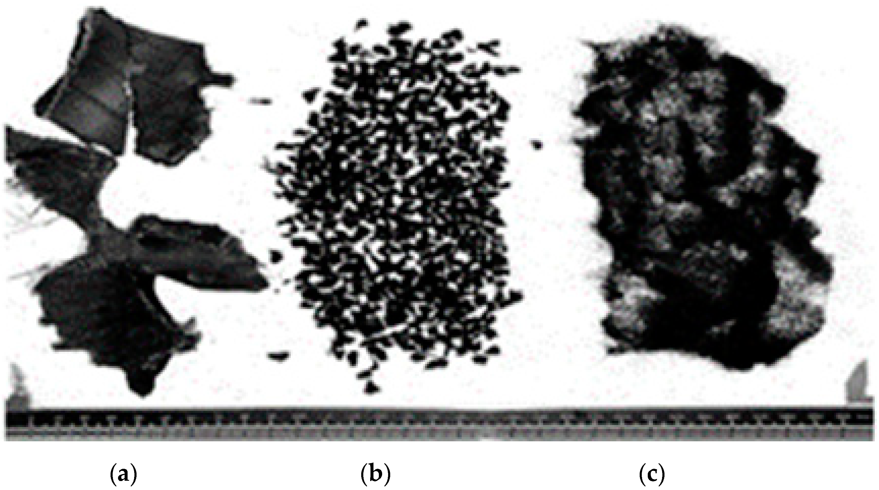
2.1. Mechanical Properties of the Materials

The mechanical properties of the materials for the tested specimens taken from the references [37,38] were defined and utilised in the numerical simulations by the ANSYS program [25], including a Poisson’s ratio of 0.18, and concrete density of 2200 kg/m3. Additionally, the modulus of elasticity of rubberised concrete in the ANSYS program [25] was defined for each model, based on the averaged experimental values stated in [37]. Hence, the typical stress and strain values for the composite material defined in the ANSYS program [25] are illustrated in Table 2.

2.2. Assumptions

The studied beam specimens were rectangular cross-sections with the dimensions of 530 mm × 150 mm × 150 mm, according to the technical specifications set in ASTM C78 [39]. The simulated beam models were characterised by the rigidity and strain properties on multiple points in the case of the plastic model. The hypotheses considered on the rubber with other concrete parts were completely linked and their properties were defined by the stress–strain curves [34,40] for individual rubber replacement ratios. Additionally, the elastic moduli were defined for all the test beam specimens. Hence, the parts replaced by the rubbers were imposed as rectangular elements with small dimensions integrated inside the beam model perpendicular to the axis, where the rubbers were distributed. Thus, they were perpendicular to the applied vertical load.

3. Finite Element Modelling

Finite element analysis is an effective tool for simulating and predicting the different properties and behaviours of composite materials that make up models through different stages of loading. This method is powerful for validating the obtained behaviours in comparison with the experimental behaviours. In the current study, a numerical analysis was conducted on the concrete beam models with the dimension of 530 mm × 150 mm × 150 mm to study the flexural and fracture behaviours under a third-point loading by using the ANSYS program [25]. To simulate the realistic behaviours of the tested beams, solid element 187 was used to represent the rubberised concrete, which is a triangular element containing ten nodes. The properties of the rubber concrete were represented by the stress–strain relationships and the defined elastic moduli for individual components within the program. For the steel plate, solid element 185 was used, which contains three degrees of freedom per nodes and is able to represent the properties of the steel plate at its supports and loading points. These two elements were used because they had high flexibilities and high loading capacities [34]. Hence, the elements had appropriate medium sizes in order to gain more accurate results since they could reflect the full responses of various elements within each model under the applied loading. Figure 3 shows the properties of the used solid element 187. For the control models (0% rubber content), the total numbers of nodes for the homogeneous and heterogeneous models were 10,080, while the total numbers of elements for the homogeneous and heterogeneous models were 3670. However, for the remaining established models, the total numbers of nodes and elements for both the homogeneous and heterogeneous models were 50,860 and 20,860, respectively. Thus, the total numbers of nodes and elements were consistent for indicating the differences in the behaviours between the selected homogeneous and heterogeneous models. Hence, the material properties were modified to simulate the different behaviours of the models.
It is necessary to state the steps for simulating the rubber concrete models under flexure in the ANSYS program [25], which are as follows:
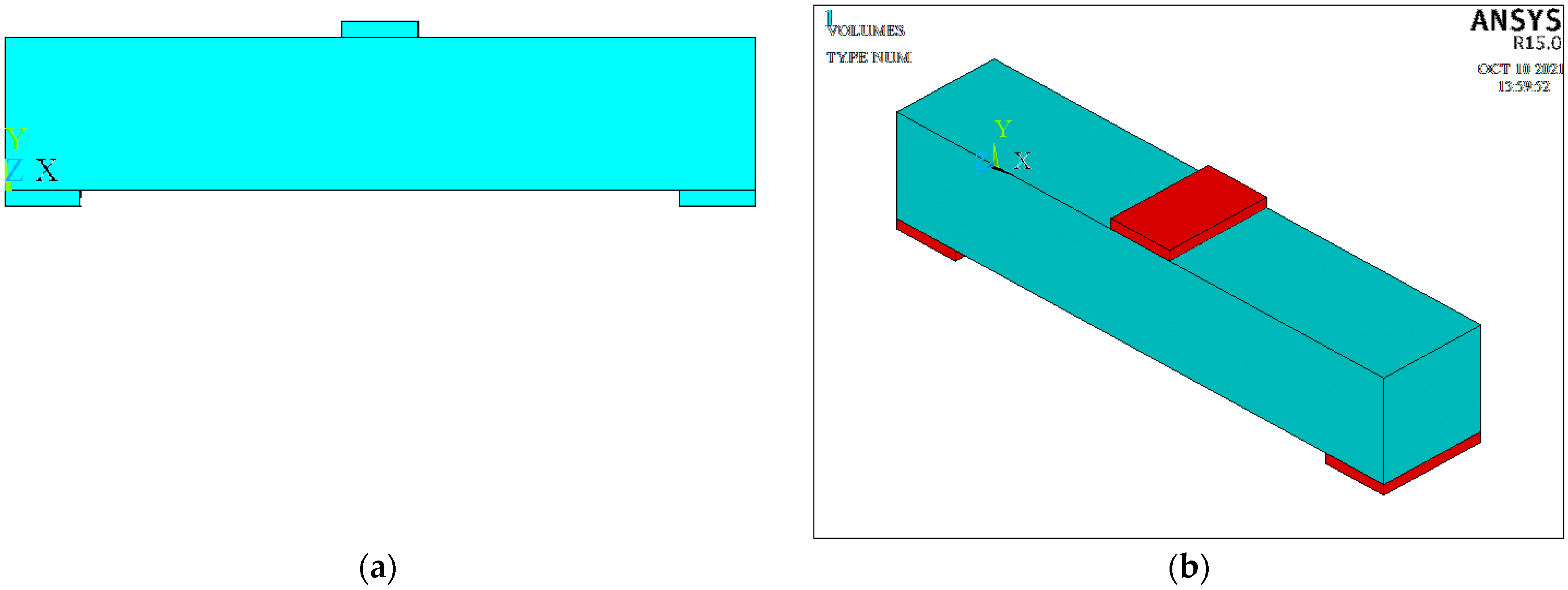
  • Determining the locations of the nodes and entering their coordinates to form the models, which were rectangle prisms with the cross-sectional dimensions of 530 mm × 150 mm × 150 mm.
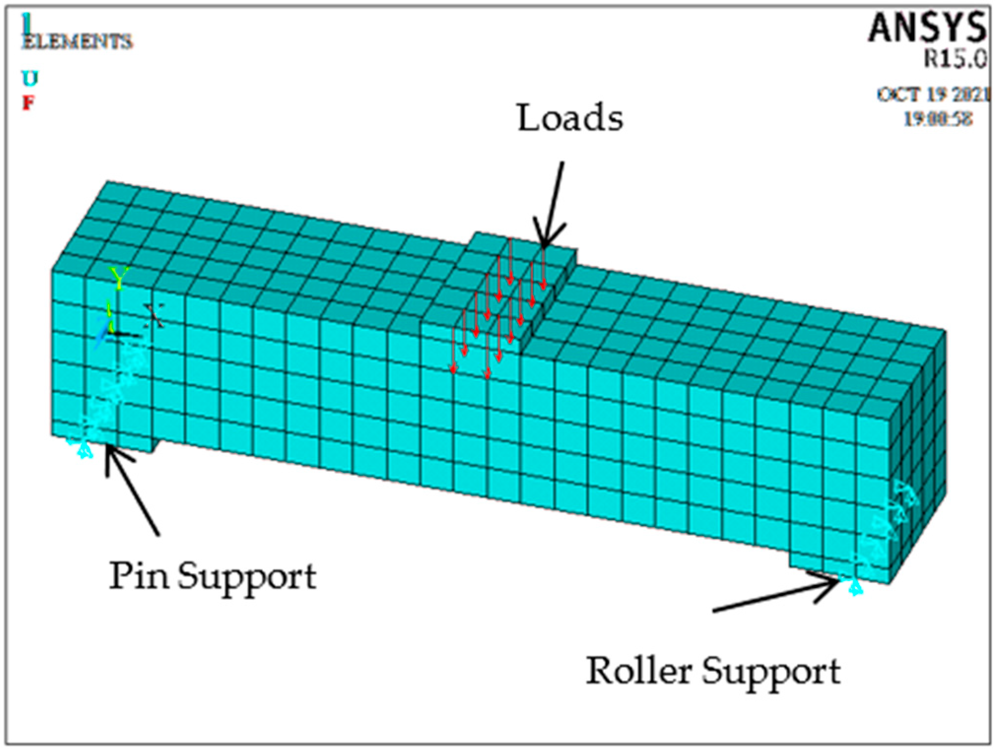
  • Determining the positions of the steel plate at the supports of the model and the applied loading points to avoid sudden failure, with the element sizes set as 50 mm × 10 mm, as shown in Figure 4.
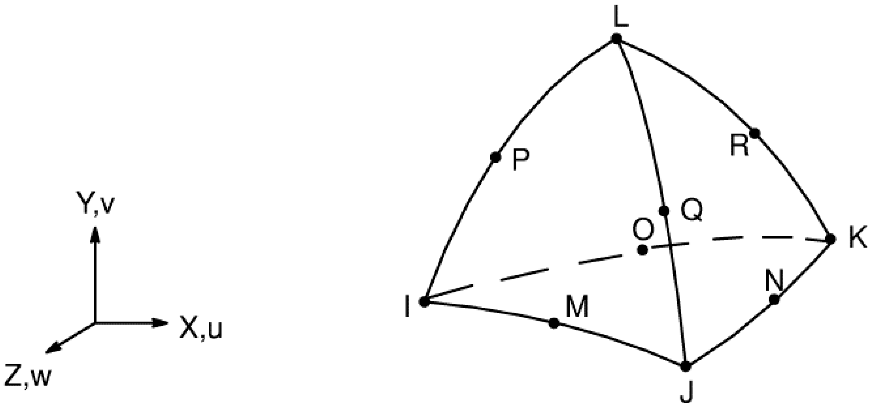
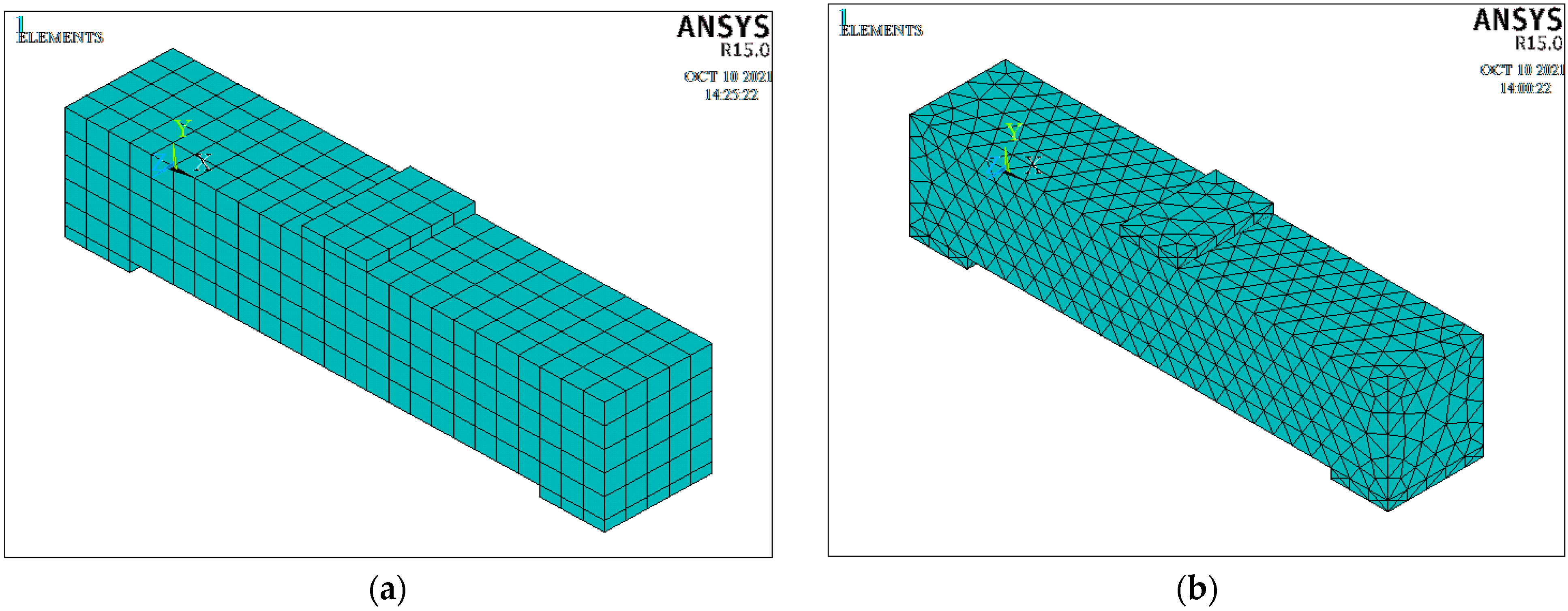
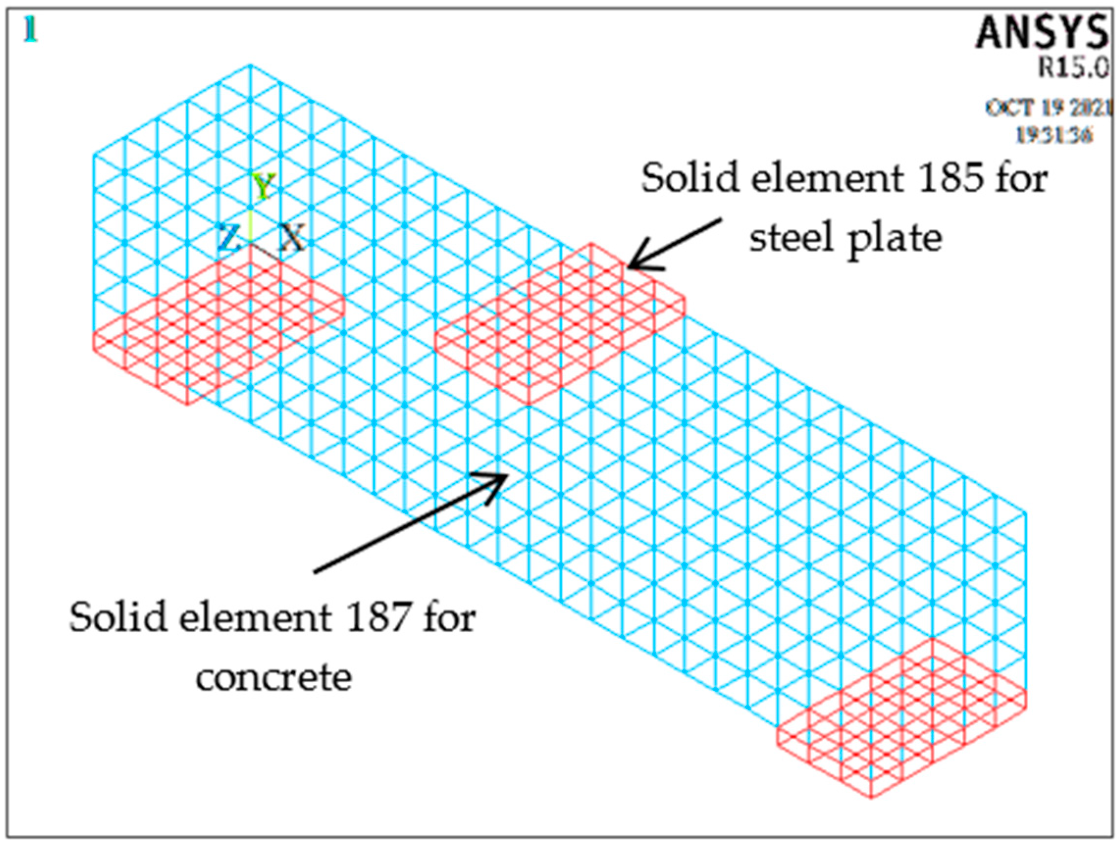
  • After deciding the geometries of the models, carrying out the meshing for the rectangular concrete beam and the supporting steel plates by specifying the properties and selecting the elements for individual materials, e.g., concrete and steel plates, and then dividing the models to small 10 mm element sizes in a homogeneous or heterogeneous manner, i.e., the concrete was represented by the solid element 187, and the steel plates were modelled by using the solid element 185, see Figure 5, Figure 6 and Figure 7.
  • Imposing a correlation between all the simulated components in the ANSYS program [25] by assuming a full bonding between the concrete and rubber parts.
  • Determining the tolerance criterion as a constraint when analysing the model, e.g., the tolerance used for deflection was 0.05.
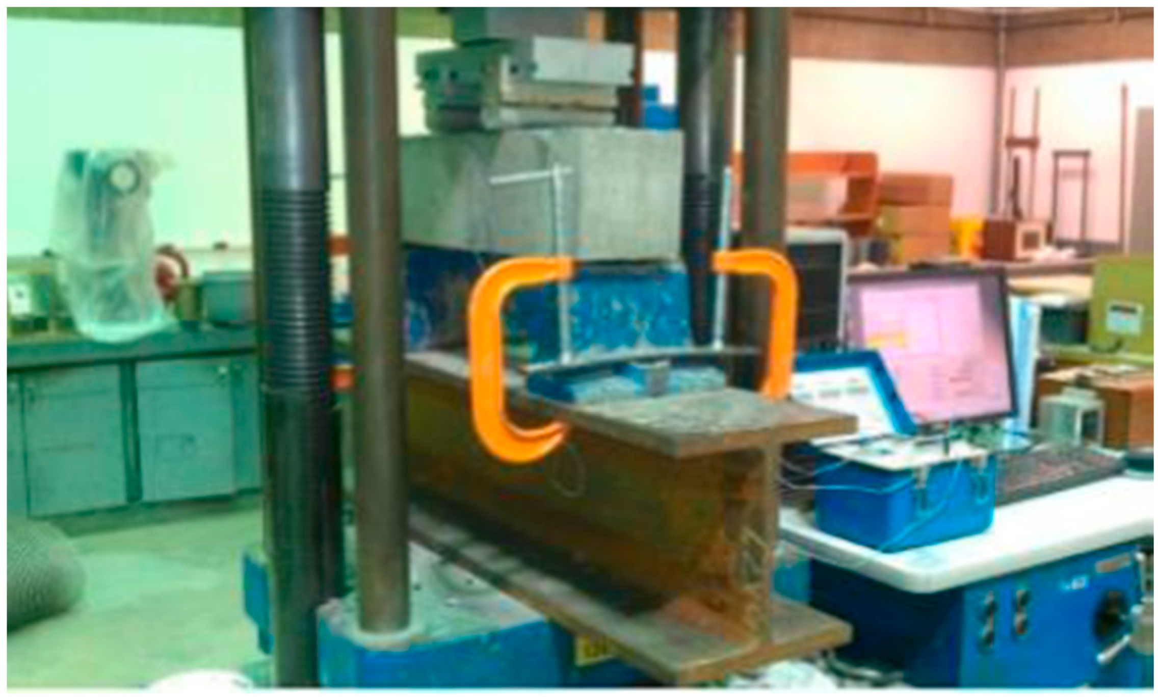
  • Designating the applied loads from the previous studies [37,38] in the top–middle regions of the models to obtain true behaviours for the simulated models, where the right support of the models was simulated as the roller support by restraining the movement in the vertical loading direction, while the left support was restrained in two directions against the movements in the vertical direction and in the direction parallel to the axis of the models as a pinned support. Hence, the applied loads were simulated gradually to be identical to the experimental loads.
  • In the analysis of the nonlinear behaviours of the models, the open and closed shear coefficients were defined as 0.2 and 0.7, with the splitting tensile modulus within the ANSYS program, [25] as stated in the references [42,43,44], with the details of the simulated beam models shown in Figure 6 and Figure 7. Hence, these parameters were defined for the simulated models as constants for the purpose of analysis.
In general, when conducting modelling analyses on a rubber concrete beam, its behaviour was elastic in an integrated manner, and would extend to the range between 0.3 fc’ to 0.85 fc’ under the applied loading. When the deformation exceeded the permissible or tolerated limit during numerical analysis, the mechanical behaviours of the concrete components became plastic. Hence, the numerical models were coherent. The plane would remain plane during loading and after loading, and the weight of the models was neglected in the numerical analysis. In the numerical analysis, the self-weight was usually ignored due to the more severe effects of the applied loading than those effects of self-weight alone. Additionally, the study simulated the behaviours of the conducted models to be comparable to the experimental behaviours under the same level of loading [42,43,44].

4. Results and Discussion

The obtained numerical results of the deflections and moduli of rupture of the rubber concrete beam models were obtained from the ANSYS program [25] by utilising the specific elements and compared with the previous experimental results [37,38]. In the numerical analysis, both homogeneous and heterogeneous meshing patterns were used for modelling the rubber concrete beams with different rubber percentage ratios of 0%, 10%, 20%, 40%, 60%, 80% and 100% as replacements for coarse aggregates in volume. Hence, the stress–strain characteristics for different rubber ratios, and the loading and attribution cases were considered during the numerical analysis. The applied load to a model could be accurately predicted and evaluated, i.e., the generated compressive stresses on the top surfaces and tensile stresses on the bottom surfaces of the beam models. The failure occurred when the tensile stresses exceeded their corresponding strengths. The maximum stresses occurred on the bottom surfaces according to the bending theory, which states that the stress is zero at the neutral axis and become larger further upwards. The deflections were analysed under the corresponding loads in order to compare the experimental and numerical results. Figure 8 shows the deflection patterns of the beam models with the homogeneous and heterogeneous meshes of 0% and 20% as rubber replacements. Their differences were higher at the mid-span under the applied loading at the elastic stage due to stress concentrations, becoming smaller in the direction towards the supports for rubber concrete models. It can be noted that a homogeneous model provided the closest behaviours to the experimental results and numerical models. The heterogeneous models contained offsets deviating from the centre of the load, which caused the numerical modelling results to deviate slightly from the experimental responses. The numerical analysis results indicates that the rubber concrete beam models failed under the flexural loading for different rubber ratios.
Figure 9 illustrates the deflection versus rubber content relationships corresponding to the maximum applied loads. The deflection values at the mid-spans of all the simulated homogeneous and heterogeneous beam models were taken for comparison with the recorded experimental results stated in [38]. It can be seen that the behaviours of the homogeneous models in the numerical simulations with the ANSYS program [25] were very close to the actual behaviours. For the homogeneous models, the variances of the numerical results in the deflections ranged from 2% to 6% compared with the experimental results for the rubber concrete beam models. These deflection versus rubber ratio relationships also showed that the agreements between the numerical and experimental results fluctuated when the percentage ratio of rubber increased.
For all heterogeneous rubberised concrete beam models, the differences between the numerical and experimental results of the mid-span deflections ranged from 2% to 7%. For the homogeneous models, the decreases in the mid-span deflection responses varied by 10.2%, 21.3% and 5.8% in comparison with the control models, which varied by 60%, 80% and 100% rubber replacements. As for the heterogeneous models, the decreases in the mid-span deflection were 10.3%, 24.4% and 6.5% in comparison with the control models with 60%, 80% and 100% rubber replacements under the maximum applied loads. However, the mid-span deflections of the rubber concrete beam models for 20% and 40% replacements increased due to a high resistance and flexibility of rubber contents in these models in comparison with other models. In general, the resistance and ductility of the rubber concrete beam models under flexural loading decreased with the increasing rubber content when this exceeded 40%. This is due to the weak resistance of the rubber relative to its high elasticity, which indicates that the resistances of the rubber concrete beam models were largely degraded with the increase in the added rubbers as the replaced aggregates. For the homogeneous and heterogeneous rubber concrete beam models, the relationships between the modulus of rupture and the rubber replacement ratio are shown in Figure 10, where the experimental values of the moduli of rupture stated in the figure were quoted by using the equations given in [37]. It was noted that the flexural resistance decreased with the increasing rubber proportion used in the mixture. This trend was consistent for both numerical and experimental results, with the differences varying between 5% and 9% [35]. For the homogeneous models, the decreases in the bending resistance were 15.1%, 24.9%, 32.1%, 38.1% and 48.5% in comparison with the control model, whereas for the heterogeneous models, the decreases in the bending resistance were 15.2%, 24.3%, 32.0%, 38.5% and 48.3% in comparison with the control model.
Additionally, the obtained numerical results of the modulus of rupture were compared with those determined in accordance with the ACI-318 specifications [45]. The average values of the modulus of rupture came from numerical simulations by calculating the stresses on the tensile sides of the examined models under flexure [34]. Numerically, the modulus of rupture decreased by 15–49% with an increase in rubber replacement proportions. However, the average decreases varied between 17% and 50% for the experimental specimens. In general, the numerical beam models and the experimental beams showed similar behaviour trends. However, there was a big discrepancy in the experimental and numerical behaviours with those predicted based on ACI-318 [45], which estimated the rupture of modulus by fr = 0.62 λ fc’, where fr, λ and fc’ are the modulus of rupture, the modification factor for light-weight concrete and the cylindrical compressive strength of concrete, respectively. Additionally, the differences between the results from the numerical analysis and the experimental results [37] were fairly small (below 10%) due to the utilised methods for evaluating and calculating the rupture modulus, i.e., the experimental and numerical methods. Furthermore, ACI-318 [45] largely underestimated the modulus of rupture, while the numerical results slightly underestimated the experimental results [37]. This is because the former was used for design, and the latter were the average values. Thus, ACI-318 [45] can primarily be used to estimate the modulus of rupture for the composite materials because it provides conservative values for design. However, it is necessary to define a new modification factor to take into account the application of other used waste materials instead of using conventional materials, e.g., gravel and sand. Hence, if the modification factor for lightweight aggregate is applied, the obtained rupture modulus is less than that for conventional concrete. Figure 11 illustrates the relationships between the applied loading and the corresponding deflections that were recorded in the experimental study [37], stated in [38] and obtained from the current numerical analysis.
In general, the results from the experimental study and the numerical modelling showed similar trends. Hence, the results of the homogeneous models were closer to the experimental results than those of the heterogeneous models due to the meshing patterns used in individual models. Additionally, it is noted that the flexural resistance of the numerical concrete beam models decreased by 15–49% with the increase in rubber content from 20% to 100% in the models, in comparison with the control model. Experimentally, the rubber content varying from 20% to 40% increased the corresponding deflections by 5–37%, while numerically, the rubber content varying from 20% to 40% increased the corresponding deflections by 5–35% because the rubbers consisted of particles with a high flexibility and low stiffness in comparison to other concrete components [13,34].
Furthermore, the ductility of the concrete beam models increased when the rubber replacement ratio increased to 40%, and this was related to the gradual distributions of the applied loading within the models until the end of the loading process. However, further increases in the rubber content above 40% would provide lower ductile models as a result of the rapid decreases in resistance and the lack of distributions of applied loadings within the models. This effect was also observed in the deflections of the concrete beam models. The evaluation of the beam models based on flexural strength or the modulus of rupture is an important way to investigate the behaviours by comparing the mechanical properties of concrete with various mix ingredients [35,36].
Table 3 illustrates the comparisons of the obtained numerical results using the ANSYS program [25] for the simulated homogeneous and heterogeneous concrete beam models, as well as their counterparts, which were experimentally obtained in [37] and are stated in reference [38]. This mainly showed the values of the modulus of rupture and the deflections for all rubber replacement ratios. Additionally, it can be noticed that, with the increasing rubber replacement ratio, the mid-span deflection values increased by 5% to 35% compared to those for the rubber replacement ratios, which varied between 20% and 40%. Hence, the homogeneous models showed larger convergences with some fluctuated variances in comparison to the heterogeneous models in terms of the simulated mid-span deflections due to the meshing patterns of the models.
Table 4 presents a statistical analysis of the numerical results of the modulus of rupture and the deflection of the concrete beam models at the failure loads, including the arithmetic means and standard deviations, showing larger convergences between the results from the numerical analysis and experimental tests [37]. Here, the numerical and experimental results of the mid-span deflections agreed very well with the errors ranging only between 2% and 7%, while the numerical and experimental results of the modulus of rupture also agreed very well with the errors ranging between 5% and 9% for the homogeneous and heterogeneous models and experimental investigations. This is mainly due to the adopted methods used for numerically and experimentally evaluating the modulus of rupture of the rubberised concrete beams.

5. Conclusions

In this study, a numerical analysis was conducted by using ANSYS program [25] for simulating the rectangular rubberised concrete beam models with various percentage ratios of rubbers to replace the coarse aggregates. The following conclusions can be drawn:
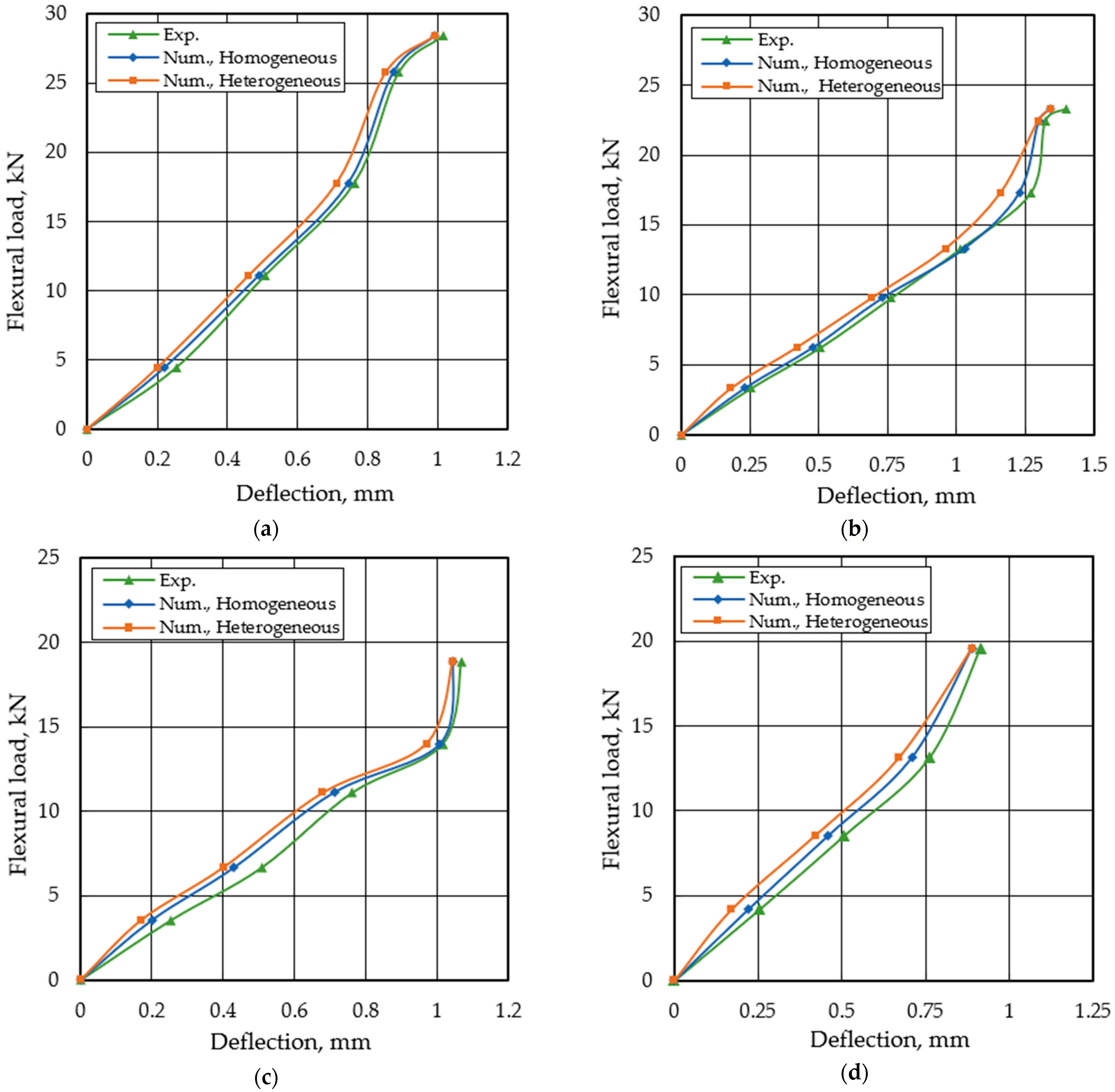
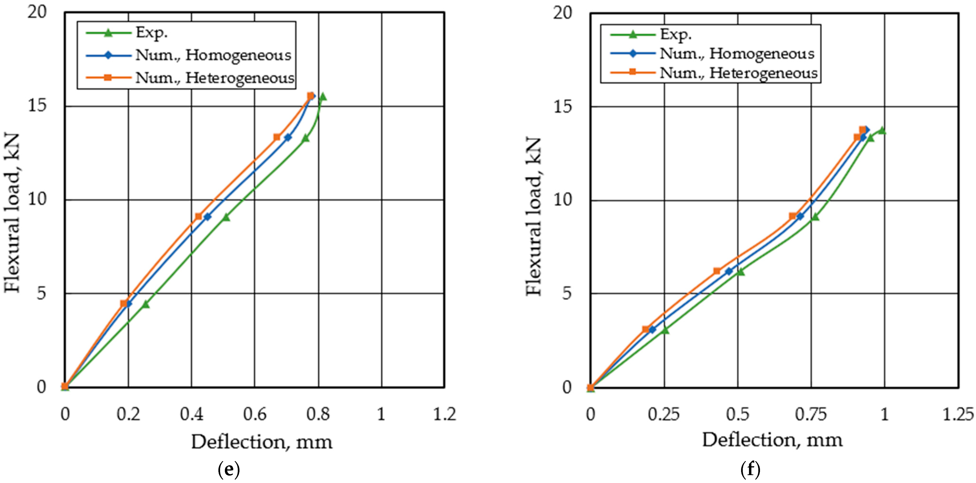
  • The numerical analysis with appropriate assumptions can be used as an effective tool to predict the structural behaviours of the rubber concrete beam models through validating the obtained numerical results with the results from the experimental investigations.
  • The behaviours of the homogeneous models were closer to those experimental behaviours than those of the heterogeneous models due to the adopted meshing methods in the individual models.
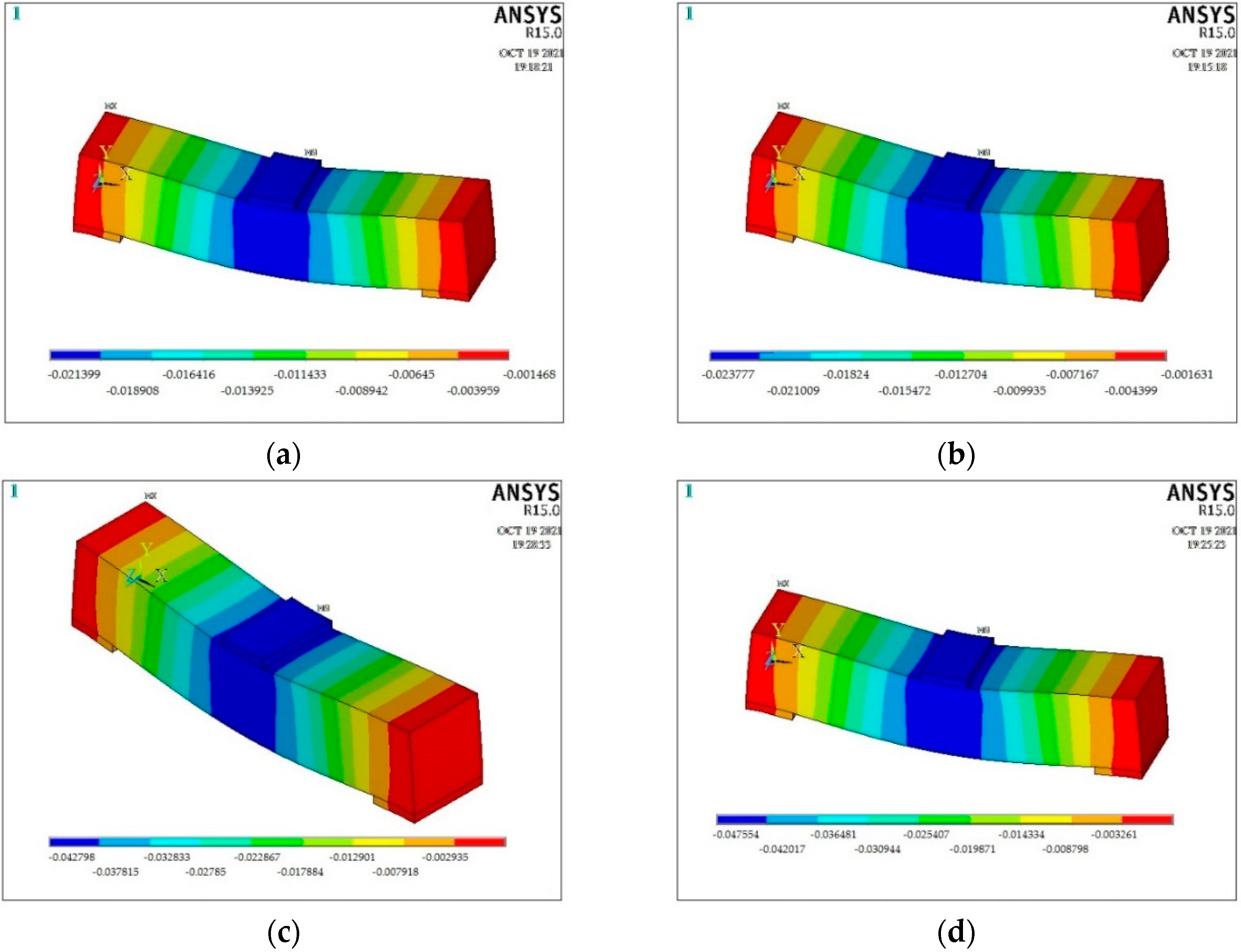
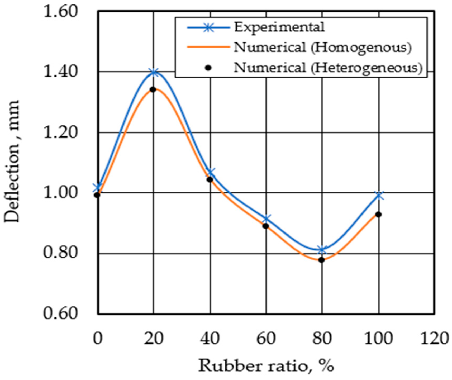
  • The mid-span deflections of the rubberised concrete beam models at the failure loadings increased with the increasing rubber content by 5% to 35% when the rubber replacement ratios varied between 20% and 40%. The variances of the deflections at the failure loadings between the numerical and experimental results ranged from 2% to 7% for the rubberised concrete beams under flexural loading.
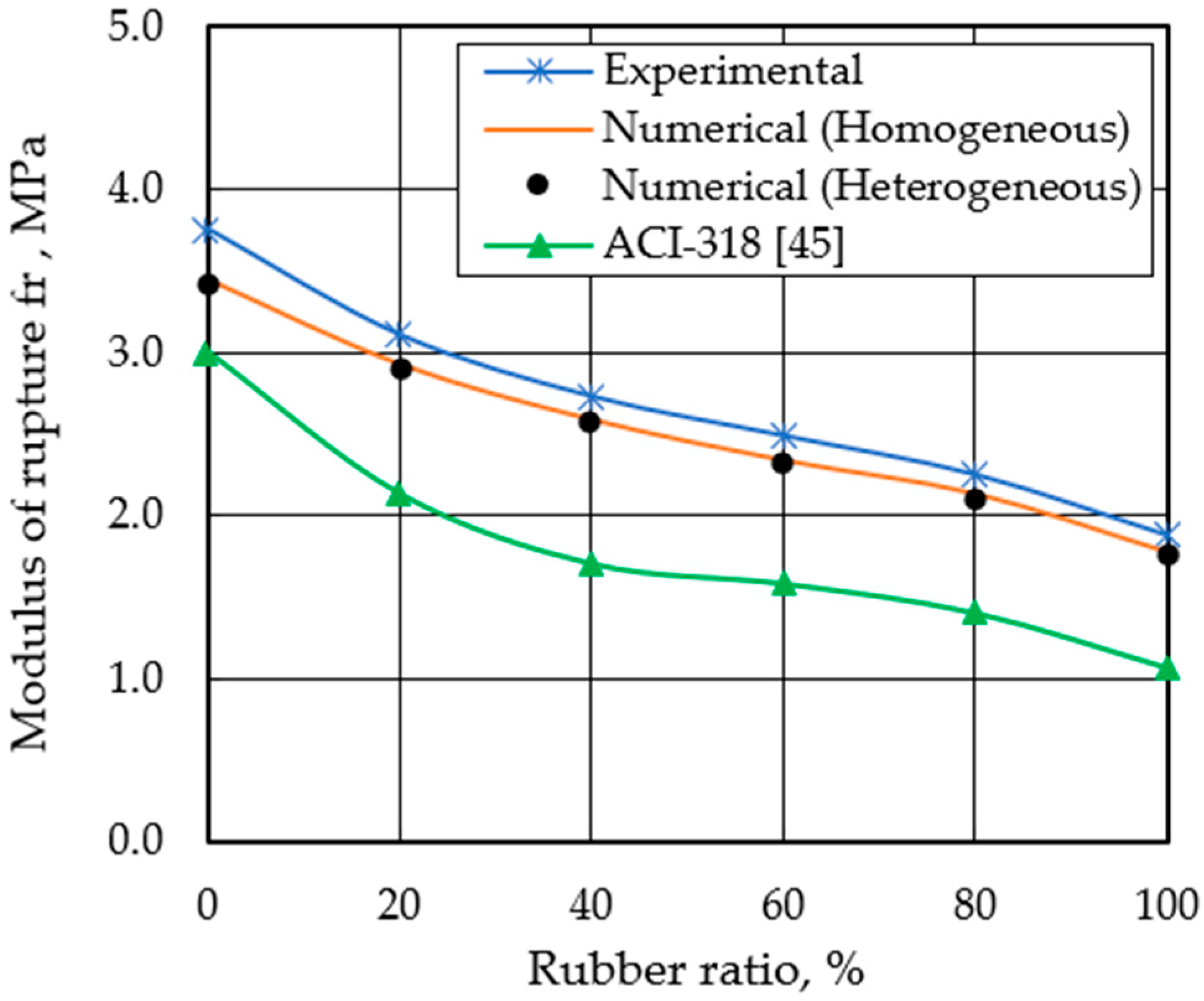
  • The flexural resistance of the numerical rubberised concrete beam models was largely degraded with the increasing content of added rubbers that replaced the coarse aggregates. The flexural strength or the modulus of rupture decreased with the increasing rubber replacement ratio by 15–49%. The numerical and experimental results of the modulus of rupture agreed very well and the differences ranged from 5% to 9% for the homogeneous and heterogeneous rubber concrete beam models and experimental studies.
  • The statistical analysis of the arithmetic means and standard deviations of the modulus of rupture, as well as the deflection of the rubberised concrete beam models at the failure loadings, indicated larger convergences between the results from the numerical analysis and experimental investigations. However, the current study is only validated for the considered materials and rubber replacement ratios. Additionally, the used numerical models can be improved and used for other investigations by modifying the relevant factors and adopting the models in the ANSYS program [25].

Author Contributions

Conceptualization, A.A.-B. and H.N.G.A.-M.; Data curation, A.A.-B., N.J.M., H.A.M. and H.N.G.A.-M.; Formal analysis, A.A.-B. and H.N.G.A.-M.; Funding acquisition, A.A.-B. and N.J.M.; Investigation, A.A.-B., N.J.M., H.A.M. and H.N.G.A.-M.; Methodology, A.A.-B., N.J.M., H.A.M. and H.N.G.A.-M.; Resources, A.A.-B., N.J.M., H.A.M., H.N.G.A.-M. and B.Z.; Validation, A.A.-B. and H.N.G.A.-M.; Visualization, A.A.-B.; Writing—Original draft, A.A.-B. and H.N.G.A.-M.; Writing—review and editing, A.A.-B. and B.Z. All authors have read and agreed to the published version of the manuscript.

Funding

This research received no external funding.

Data Availability Statement

The data are available upon request from the first author of the paper.

Acknowledgments

The authors would like to thank Mustansiriyah University, (https://uomustansiriyah.edu.iq/), Baghdad, Iraq, for its support to the present work. The authors from this university are very grateful for the cooperation of Glasgow Caledonian University in Glasgow, Scotland, UK.

Conflicts of Interest

The authors declare no conflict of interest.

References

  1. Nehdi, M.; Khan, A. Cementitious composites containing recycled tire rubber: An overview of engineering properties and potential applications. Cem. Concr. Aggreg. 2001, 23, 3–10. [Google Scholar]
  2. Thomas, B.S.; Gupta, R.C.; Kalla, P.; Cseteneyi, L. Strength, abrasion and permeation characteristics of cement concrete containing discarded rubber fine aggregates. Constr. Build. Mater. 2014, 59, 204–212. [Google Scholar] [CrossRef]
  3. Farzampour, A. Temperature and humidity effects on behavior of grouts. Adv. Concr. Constr. 2017, 5, 659–669. [Google Scholar] [CrossRef]
  4. Sofi, A. Effect of waste tyre rubber on mechanical and durability properties of concrete—A review. Ain Shams Eng. J. 2018, 9, 2691–2700. [Google Scholar] [CrossRef]
  5. Luhar, S.; Chaudhary, S.; Luhar, I. Development of rubberized geopolymer concrete: Strength and durability studies. Constr. Build. Mater. 2019, 204, 740–753. [Google Scholar] [CrossRef]
  6. Chalangaran, N.; Farzampour, A.; Paslar, N. Nano silica and metakaolin effects on the behavior of concrete containing rubber crumbs. CivilEng 2020, 1, 264–274. [Google Scholar] [CrossRef]
  7. Mansouri, I.; Shahheidari, F.S.; Hashemi, S.M.A.; Farzampour, A. Investigation of steel fiber effects on concrete abrasion resistance. Adv. Concr. Constr. 2020, 9, 367–374. [Google Scholar] [CrossRef]
  8. Chalangaran, N.; Farzampour, A.; Paslar, N.; Fatemi, H. Experimental investigation of sound transmission loss in concrete containing recycled rubber crumbs. Adv. Concr. Constr. 2021, 11, 447–454. [Google Scholar] [CrossRef]
  9. Malarvizhi, G.; Senthil, N.; Kamaraj, C. A study on recycling of crumb rubber and low density polyethylene blend on stone matrix asphalt. Int. J. Sci. Res. Publ. 2012, 2, 1–16. [Google Scholar]
  10. Thomas, B.S.; Gupta, R.C. A comprehensive review on the applications of waste tire rubber in cement concrete. Renew. Sustain. Energy Rev. 2016, 54, 1323–1333. [Google Scholar] [CrossRef]
  11. Benazzouk, A.; Douzane, O.; Langlet, T.; Mezreb, K.; Roucoult, J.M.; Quéneudec, M. Physico-mechanical properties and water absorption of cement composite containing shredded rubber wastes. Cem. Concr. Compos. 2007, 29, 732–740. [Google Scholar] [CrossRef]
  12. Zhu, H. Rubber Concrete—Rapra Handbook on Polymers in Construction; Rapra Technology Limited: Shrewsbury, UK, 2005. [Google Scholar]
  13. Topçu, İ.B. Assessment of the brittleness index of rubberized concretes. Cem. Concr. Res. 1997, 27, 177–183. [Google Scholar] [CrossRef]
  14. Yang, L.H. Study on Brittleness and Ductility of CRC and the Application in the Cover Layers of Bridges. Master Thesis, Tianjin University, Tianjin, China, 2007. [Google Scholar]
  15. Benazzouk, A.; Mezreb, K.; Doyen, G.; Goullieux, A.; Quéneudec, M. Effect of rubber aggregates on the physico-mechanical behaviour of cement–rubber composites-influence of the alveolar texture of rubber aggregates. Cem. Concr. Compos. 2003, 25, 711–720. [Google Scholar] [CrossRef]
  16. Osama, Y.; Mohamed, A.E.; Julie, E.M.; Xing, M. An experimental investigation of crumb rubber concrete confined by fibre reinforced polymer tubes. Constr. Build. Mater. 2014, 53, 522–532. [Google Scholar]
  17. Guo, Y.C.; Zhang, J.H.; Chena, G.; Chen, G.M.; Xie, Z.H. Fracture behaviors of a new steel fiber reinforced recycled aggregate concrete with crumb rubber. Constr. Build. Mater. 2014, 53, 32–39. [Google Scholar] [CrossRef]
  18. Mohammed, B.S.; Awang, A.B.; Wong, S.S.; Nhavene, C.P. Properties of nano silica modified rubbercrete. J. Clean. Prod. 2016, 119, 66–75. [Google Scholar] [CrossRef]
  19. Topçu, İ.B. The properties of rubberized concretes. Cem. Concr. Res. 1995, 25, 304–310. [Google Scholar] [CrossRef]
  20. Toutanji, H.A. The use of rubber tire particles in concrete to replace mineral aggregates. Cem. Concr. Compos. 1996, 18, 135–139. [Google Scholar] [CrossRef]
  21. Contreras-Marín, E.; Anguita-García, M.; Alonso-Guzmán, E.M.; Jaramillo-Morilla, A.; Mascort-Albea, E.J.; Romero-Hernández, R.; Soriano-Cuesta, C. Use of granulated rubber tyre waste as lightweight backfill material for retaining walls. Appl. Sci. 2021, 13, 6159. [Google Scholar] [CrossRef]
  22. Chan, C.W.; Yu, T.; Zhang, S.S.; Xu, Q.F. Compressive behaviour of FRP-confined rubber concrete. Constr. Build. Mater. 2019, 211, 416–426. [Google Scholar] [CrossRef]
  23. Segre, N.; Joekes, I. Use of tire rubber particles as addition to cement paste. Cem. Concr. Res. 2000, 30, 1421–1425. [Google Scholar] [CrossRef]
  24. Pacheco-Torgal, F.; Ding, Y.; Jalali, S. Properties and durability of concrete containing polymeric wastes (tyre rubber and polyethylene terephthalate bottles): An overview. Constr. Build. Mater. 2012, 30, 714–724. [Google Scholar] [CrossRef] [Green Version]
  25. ANSYS Inc. ANSYS Fluent User’s Guide; Release 15; ANSYS, Inc.: Irvine, CA, USA, 2013. [Google Scholar]
  26. Briody, C.; Duignan, B.; Jerrams, S.; Tiernan, J. The Implementation of a viscohyperelastic numerical material model for simulating the behaviour of polymer foam materials. J. Comput. Mater. Sci. 2012, 64, 47–51. [Google Scholar] [CrossRef] [Green Version]
  27. Ren, R.; Liang, J.-F.; Liu, D.-W.; Gao, J.-H.; Chen, L. Mechanical behavior of crumb rubber concrete under axial compression. Adv. Concr. Constr. 2020, 9, 249–256. [Google Scholar]
  28. Barbuta, M.; Diaconu, D.; Serbanoiu, A.A.; Burlacu, A.; Timu, A.; Gradinaru, C.M. Effects of tire wastes on the mechanical properties of concrete. Procedia Eng. 2017, 181, 346–350. [Google Scholar] [CrossRef]
  29. Bedi, R.; Chandra, R.; Singh, S.P. Mechanical properties of polymer concrete. J. Compos. 2013, 2013, 1–12. [Google Scholar] [CrossRef] [Green Version]
  30. Huang, B.; Li, G.; Pang, S.-S.; Eggers, J. Investigation into waste tire rubber-filled concrete. J. Mater. Civ. Eng. 2004, 16, 187–194. [Google Scholar] [CrossRef]
  31. Li, G.; Garrick, G.; Eggers, J.; Abadie, C.; Stubblefield, M.A.; Pang, S.-S. Waste tire fiber modified concrete. Compos. Part B Eng. 2004, 35, 305–312. [Google Scholar] [CrossRef]
  32. Zheng, L.; Huo, X.S.; Yuan, Y. Experimental investigation on dynamic properties of rubberized concrete. Constr. Build. Mater. 2008, 22, 939–947. [Google Scholar] [CrossRef]
  33. Ganjian, E.; Khorami, M.; Maghsoudi, A.A. Scrap-rubber replacement for aggregate and filler in concrete. Constr. Build. Mater. 2009, 23, 1828–1836. [Google Scholar] [CrossRef]
  34. Baetu, S.A.; Venghiac, V.M.; Budescu, M.; Taranu, N. Numerical simulation of concrete with rubber aggregates. In Proceedings of the 15th International Multidisciplinary Scientific GeoConference Surveying Geology and Mining Ecology Management, SGEM, Albena, Bulgaria, 18–24 June 2015; pp. 345–352. [Google Scholar]
  35. Mendis, A.S.M.; Al-Deen, S.; Ashraf, M. Effect of rubber particles on the flexural behaviour of reinforced crumbed rubber concrete beams. Constr. Build. Mater. 2017, 154, 644–657. [Google Scholar] [CrossRef]
  36. Jafari, K.; Toufigh, V. Experimental and analytical evaluation of rubberized polymer concrete. Constr. Build. Mater. 2017, 155, 495–510. [Google Scholar] [CrossRef]
  37. Miller, N.M.; Tehrani, F.M. Mechanical properties of rubberized lightweight aggregate concrete. Constr. Build. Mater. 2017, 147, 264–271. [Google Scholar] [CrossRef]
  38. Shamasundar, S.G. 3-D Numerical Modeling and Analysis of Mechanical Properties of Rubberized Concrete. Master’s Thesis, Lyles College of Engineering, California State University, Fresno, CA, USA, 2017. [Google Scholar]
  39. ASTM Designation C78; Standard Test Method for Flexural Strength of Concrete (Using Simple Beam with Third-Point Loading). American Society for Testing and Material: Philadelphia, PA, USA, 2016.
  40. Duarte, A.P.C.; Silvestre, N.; de Brito, J.; Julio, E. Numerical study of the compressive mechanical behaviour of rubberized concrete using the extended Finite Element Method. Compos. Struct. 2017, 179, 132–145. [Google Scholar] [CrossRef]
  41. ANSYS. ANSYS Theory Reference, 11th ed.; Release 5.6, 001242; SAS IP, Inc.: Canonsburg, PA, USA, 1999. [Google Scholar]
  42. Al-Maliki, H.; Al-Balhawi, A.; Al-shimmeri, A.J.H.; Zhang, B. Structural efficiency of hollow reinforced concrete beams subjected to partial uniformly distributed loading. Buildings 2021, 11, 391. [Google Scholar] [CrossRef]
  43. Al-Maliki, H.; Al-Balhawi, A.; Al-Taai, S.R.; Madhloom, H.M.; Gamil, Y. Structural behavior of precast high strength reinforced concrete Vierendeel truss walls: A numerical approach. Int. J. Geomate 2021, 21, 137–150. [Google Scholar] [CrossRef]
  44. Al-Maliki, H.; Abbass, M.M.; Al-kaabi, J.J. Simulation nonlinear of structural behavior of hollow reinforced concrete deep beams strengthened by CFRP. In IOP Conference Series: Materials Science and Engineering; IOP: Bristol, UK, 2020; Volume 928. [Google Scholar]
  45. ACI Committee-318; Building Code Requirements for Structural Concrete. American Concrete Institute: Indianapolis, IN, USA, 2019.
Figure 1. Waste tyre rubber classifications: (a) Chipped, (b) crumb, (c) ground rubber [21].
Buildings 12 00590 g001
Figure 2. Detailed third-point bending test setup for a typical specimen [Reprinted/adapted with permission from Ref. [37]. 2022, Elsevier].
Buildings 12 00590 g002
Figure 3. Solid element 187 [41].
Buildings 12 00590 g003
Figure 4. Details of a typical beam model: (a) Front view of the beam model, (b) 3D view of the solid beam model.
Buildings 12 00590 g004
Figure 5. Different meshing patterns of a typical beam: (a) Homogeneous model, (b) heterogeneous model.
Buildings 12 00590 g005
Figure 6. 3D view of the concrete and steel plate elements (wireframes) of a typical beam model.
Buildings 12 00590 g006
Figure 7. Supports and applied loads for a typical beam model.
Buildings 12 00590 g007
Figure 8. 3D views of the deflection patterns of typical beam models: (a) Rubber ratio = 0% (homogeneous), (b) rubber ratio = 0% (heterogeneous), (c) rubber ratio = 20% (homogeneous), (d) rubber ratio = 20% (heterogeneous).
Buildings 12 00590 g008
Figure 9. Deflection versus rubber content relationships of all the concrete beam models.
Buildings 12 00590 g009
Figure 10. Modulus of rupture versus rubber content relationships for all beam models.
Buildings 12 00590 g010
Figure 11. Flexural load—deflection relationships of all the concrete beam models with different rubber ratios: (a) Rubber ratio 0%, (b) rubber ratio 20%, (c) rubber ratio 40%, (d) rubber ratio 60%, (e) rubber ratio 80%, (f) rubber ratio 100%.
Buildings 12 00590 g011aBuildings 12 00590 g011b
Table 1. Mix designs of the tested rubber concrete [37].
Content(0% Rubber)20%40%60%80%100%
* W (kg)250250250250250250
C (kg)500500500500500500
* S (kg)850850850850850850
* G (kg)500450175125250.00
* C.R. (kg)0.0050200250300350
Note: *—estimated, W—water, C—cement, S—sand, G—gravel, C.R.—crumb rubber.
Table 2. Typical stress–strain values for the rubberised concrete defined in ANSYS program [25].
Stress (MPa)Strain (mm/mm)
7.650.00033
11.680.00091
15.260.00135
18.760.00160
20.170.00220
20.170.00300
Table 3. Comparisons of the experimental and numerical results of the modulus of rupture and the mid-span deflection at failure loadings.
Mix
No.
Experimental [37,38]Numerical
(Homogeneous Models)
Numerical
(Heterogeneous Models)
fr (MPa)Defl. (mm)fr (MPa)Defl. (mm)fr (MPa)Defl. (mm)
03.7601.0163.4500.9923.4100.990
203.1091.3972.9301.3432.8901.341
402.7301.0672.5901.0452.5801.044
602.4880.9142.3400.8902.3200.888
802.2480.8132.1350.7802.0950.778
1001.8740.9911.7760.9351.7620.926
Table 4. Statistical data on the experimental and numerical results of the modulus of rupture and mid-span deflection at the failure loads.
Mix
No.
Experimental
[37,38]
Numerical
Homogeneous
Num./Exp.Numerical
Heterogeneous
Num./Exp.
fr (MPa)Defl. (mm)fr (MPa)Defl. (mm)fr
%
Defl.
%
fr (MPa)Defl.
(mm)
fr
%
Defl.
%
03.7601.0163.4500.99291.7697.643.4100.99090.6997.44
203.1091.3972.9301.34394.2496.132.8901.34192.9695.99
402.7301.0672.5901.04594.8797.942.5801.04494.5197.84
602.4880.9142.3400.89094.0597.372.3200.88893.2597.16
802.2480.8132.1350.78094.9795.942.0950.77893.1995.69
1001.8740.9911.7760.93594.7794.351.7620.92694.0293.44
Mean94.1196.56 93.1096.26
STD1.101.24 1.201.47
Publisher’s Note: MDPI stays neutral with regard to jurisdictional claims in published maps and institutional affiliations.

