Article

Central Load-Bearing Control in the Construction Process of the Concrete Spherical Joint Nandu River Swing Bridge: A Case Study

1
Department of Civil Engineering, Wuhan University of Technology, Wuhan 430070, China
2
Department of Built Environment, Eindhoven University of Technology, 5612 AZ Eindhoven, The Netherlands
*
Author to whom correspondence should be addressed.
Buildings 2022, 12(5), 511; https://doi.org/10.3390/buildings12050511
Submission received: 28 February 2022 / Revised: 14 April 2022 / Accepted: 19 April 2022 / Published: 20 April 2022
(This article belongs to the Topic Advances in Construction and Project Management)

Abstract

:
The rotating mechanism is a significant procedure in swing bridges. In this paper, the Nandu River swing bridge is taken as an engineering case study to exhibit the critical technology of the monitoring process and the construction method of the swing bridge. The research focuses on the central load-bearing control system used to guarantee the security of the construction process. The mechanical problems during the construction process are discussed. Simultaneously, the cable tension and gravity center test are introduced. The non-Hertz contact theory is utilized to calculate the stress distribution of the spherical joint. Furthermore, the overturning moment is computed to monitor the stability of the rotating system based on the stress distribution calculation of the spherical joint. The monitoring process of central load-bearing control is entirely exhibited and discussed. Concurrently, the calculating result of the real-time overturning moment reflects the stability of the rotating construction process, and adjustments are made to ensure the safety of construction. The results show that, during the cable tension process, the middle position of the main arch exhibited 162.3 mm maximum vertical displacement. Meanwhile, the fraction moment was greatly larger than the unbalanced moment. Furthermore, the maximum overturning moment value was 2094.38 kN·m, which was smaller than the resistance of the overturning moment. The present research demonstrates that the non-Hertz contact theory fits the calculation of spherical joint stress distribution. Simultaneously, the middle position of the main arch should be monitored to control the vertical displacement at the cable tensioning stages. The gravity center test and stability control of the rotating construction are the key steps to reaching central load-bearing control.

1. Introduction

A bridge is a structure built to span a physical obstacle (such as a body of water, valley, road, or rail) without blocking the way underneath. It is constructed for the purpose of providing passage over the obstacle, which is usually something that is otherwise difficult or impossible to cross [1,2]. The technology of rotating construction is an unusual building method caused by the surrounding topography and site of the bridge construction [3]. The rotating construction divides the bridge into two rotating systems (shown in Figure 1a) on each side of the bank or mountain. Then, the rotating system is separated from the temporary supports and rotated from the bridge axis to the butt at the proper time [4]. Several bridges have been built using rotating construction worldwide [5]. In recent decades, in order to reduce the impact on existing railway lines or municipal facilities, as well as cross valleys and other complex topographical sites, rotating construction has been widely utilized [6,7]. Consequently, the structure of the swing bridge rotating system has characteristics of large mass and ultra-long cantilevers. Therefore, to ensure the security of swing bridge construction, an investigation into central load-bearing control is needed. This procedure significantly influences the overturning moment during the rotating construction process.
Rotating construction is utilized in long-span swing bridges, and the superstructure of swing bridges commonly utilize long-span cantilever structures. However, they are easy to overturn and collapse during the rotating construction process [8]. During the rotating process, all the mass of the rotating system is applied to the upper rotating table, and lifting jacks push the upper rotating table to rotate the rotating system to a specific position of bridge arch closure. The rotating system and the spherical joint (Figure 1b) are hinged to the lower rotating table. Therefore, the fraction between the upper spherical joint and the lower spherical joint provides resistance to the structural overturn of the rotating system [9]. Therefore, the entire building process and the subsequent analysis of the swing bridge are important to bridging security. Simultaneously, unbalanced weight results in the gravity eccentric of the rotating system. The gravity eccentric can cause a large overturning moment, resulting in the overturn of the whole structure [10]. Alocci et al. [11] studied the lightweight swing bridge, and the main span of the bridge was 21.26 m. A feasibility study presented an asymmetric, cable-stayed, pedestrian swing bridge. However, the construction of bridges crossing valleys or rivers are of a larger scale. Therefore, the overturning moments are harder to control compared to lightweight swing bridges. At the same time, the overturning moment mainly appears at the spherical joint. The spherical joint [12] is the key component that bears the mass of all rotating systems. Generally, the steel spherical joint is utilized to undertake the gravity of the rotating system. However, the transportation and the installation of steel spherical joints are large challenges in mountainous area [13]. Therefore, ordinary reinforced concrete is often selected to be the material of the spherical joint. Meanwhile, the load capacity of reinforced concrete spherical joints is lower than that of steel spherical joints. Consequently, the distribution of contact stress on the spherical joint is a critical limit, depending on the allowable load capacity of the reinforced concrete material. Besides, the construction of other components is also important in the bridge construction process. Fuchs [4] studied the practical construction process of the El Ferdan Swing Bridge. Meanwhile, Watanabe et al. [14] characterized the whole construction process of the Yumeshima–Maishima Swing Bridge. However, the monitoring processes for the construction of these swing bridges were not presented in the studies. Furthermore, significant procedure testing details, including the determination of the gravity center of the rotating system, were not reported. Therefore, an overview of the entire construction process is necessary. The gravity center of the rotating system is the critical parameter to calculate the weight of the counterweight, and the distribution of contact stress on the surface is another important factor to ensure the central load-bearing of the special joint.
The objective of this research was to investigate central load-bearing control and the construction process of concrete spherical joint swing bridges. Concrete spherical joint contact stress is triggered by the weight of rotating system, so the non-Hertz contact theory can be applied in terms of the contact stress distribution of the concrete spherical joint. Before the rotating construction procedure, the gravity center test needs to be utilized to detect the gravity position of the rotating system after the cable tension stage. Subsequently, we propose a deducted formula based on non-Hertz contact theory to calculate the overturning moment during the rotating construction process. Meanwhile, the inclination monitoring system can be used on the back wall of the swing bridge to monitor the overturning moment in the process of the rotating construction in order to enhance the safety of the bridge construction.

2. Mechanical Problems of the Superstructure

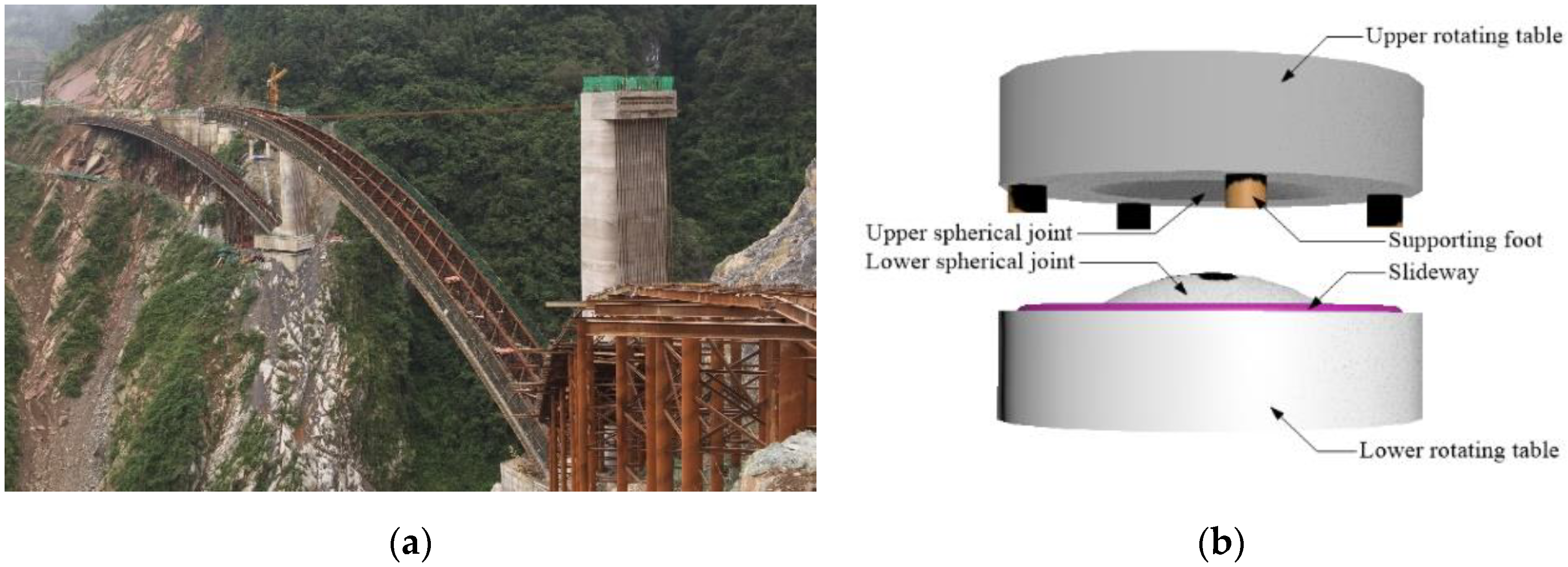
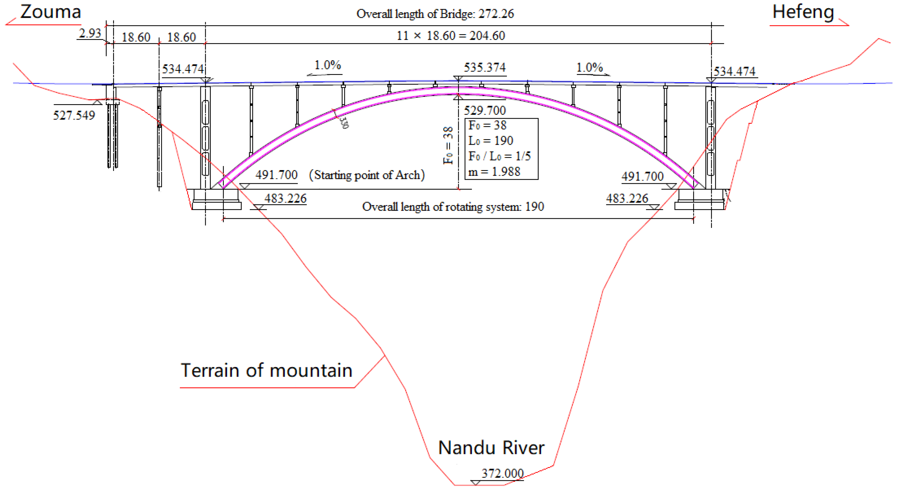
2.1. Case Study Description

The construction of the Nandu River Swing Bridge is taken as an engineering case study (shown in 0); the bridge is the largest concrete spherical joint swing bridge in China, spans 190 m (L0), and is located in the Enshi province. The sagitta height (F0) is 38 m and the F0/L0 ratio is 1/5. Meanwhile, the arch axis coefficient (m) is 1.988. The design speed of the bridge is 40 km/h. The rotating system is formed by the rigid skeleton and the bottom of the rigid skeleton is cast by the concrete. The back wall provides a balanced weight during the process of rotating construction. The reinforced concrete spherical joint is cast by C50 concrete. Detailed information, in terms of the back wall and the spherical joint, is presented in Section 4 and Section 5. Figure 2 shows the bridge layout of the Nandu River Swing Bridge.

2.2. Construction Process of the Superstructure

Fuchs [4] expounded on the construction process of swing bridges using a case study. However, the construction of the Nandu River Swing Bridge is different: the rotating system of the bridge is an asymmetrical superstructure. The construction process of the superstructure is shown in Figure 3. Detailed information is presented below.
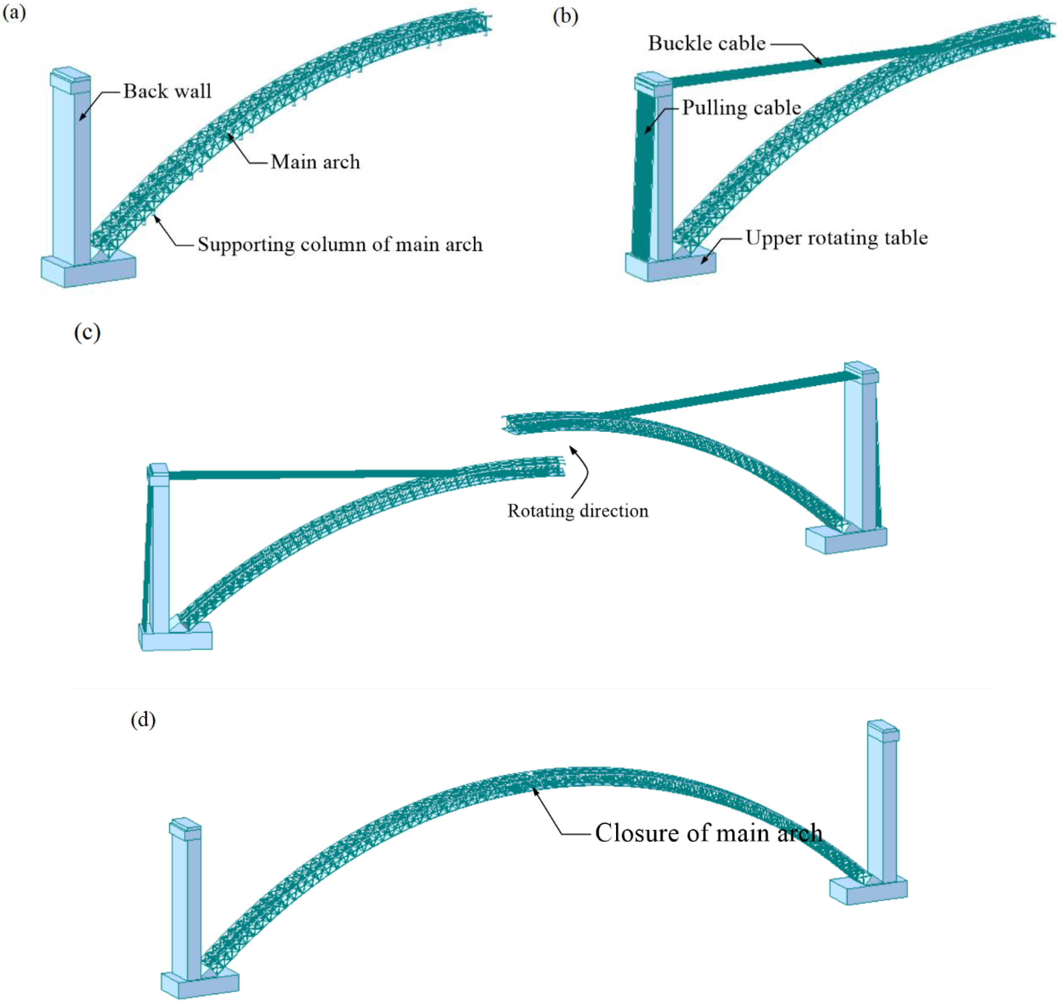
  • The main arch is built along the surrounding mountainous terrain (Figure 3a);
  • After the tension of the buckle cable and pulling cable, the entire rotating system is supported by the concrete spherical joint. If the gravity center of the system coincides with the axis of the concrete spherical joint, the system is only held up by the upward force of the concrete spherical joint. The overturning resistance of the entire system is kept in a low-security state; therefore, the closure procedure needs to be implemented immediately (Figure 3b);
  • In terms of the rotating process of the swing bridge (Figure 3c), the rotating systems are derived from horizontal lifting jacks at the upper rotating table in no-wind weather;
  • Structural stiffness increases after the closure and the dismantlement of the cable, and the structure is in a stable state (Figure 3d). The entire structural weight is forced by the arch foot, forming the non-hinged arch. Under the action of self-weight and external load, the bending moment distribution in the arch is uniformly distributed along the main arch;
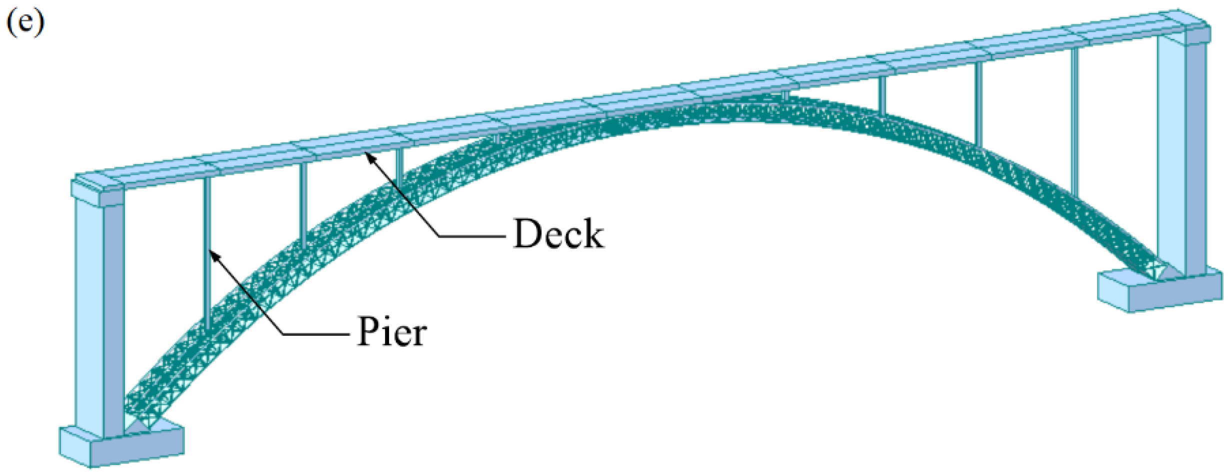
  • The pier founded on the main arch and the bridge deck are cast during the programmatic process, and the ancillary facilities are installed in sequence (Figure 3e).

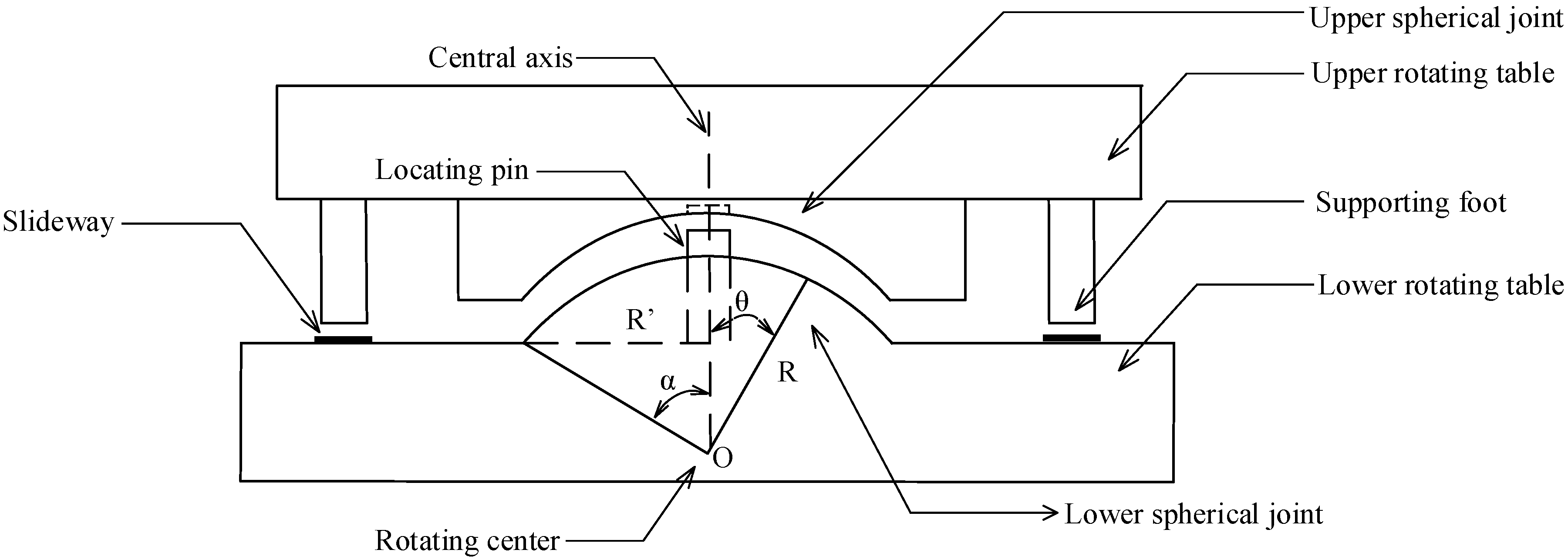
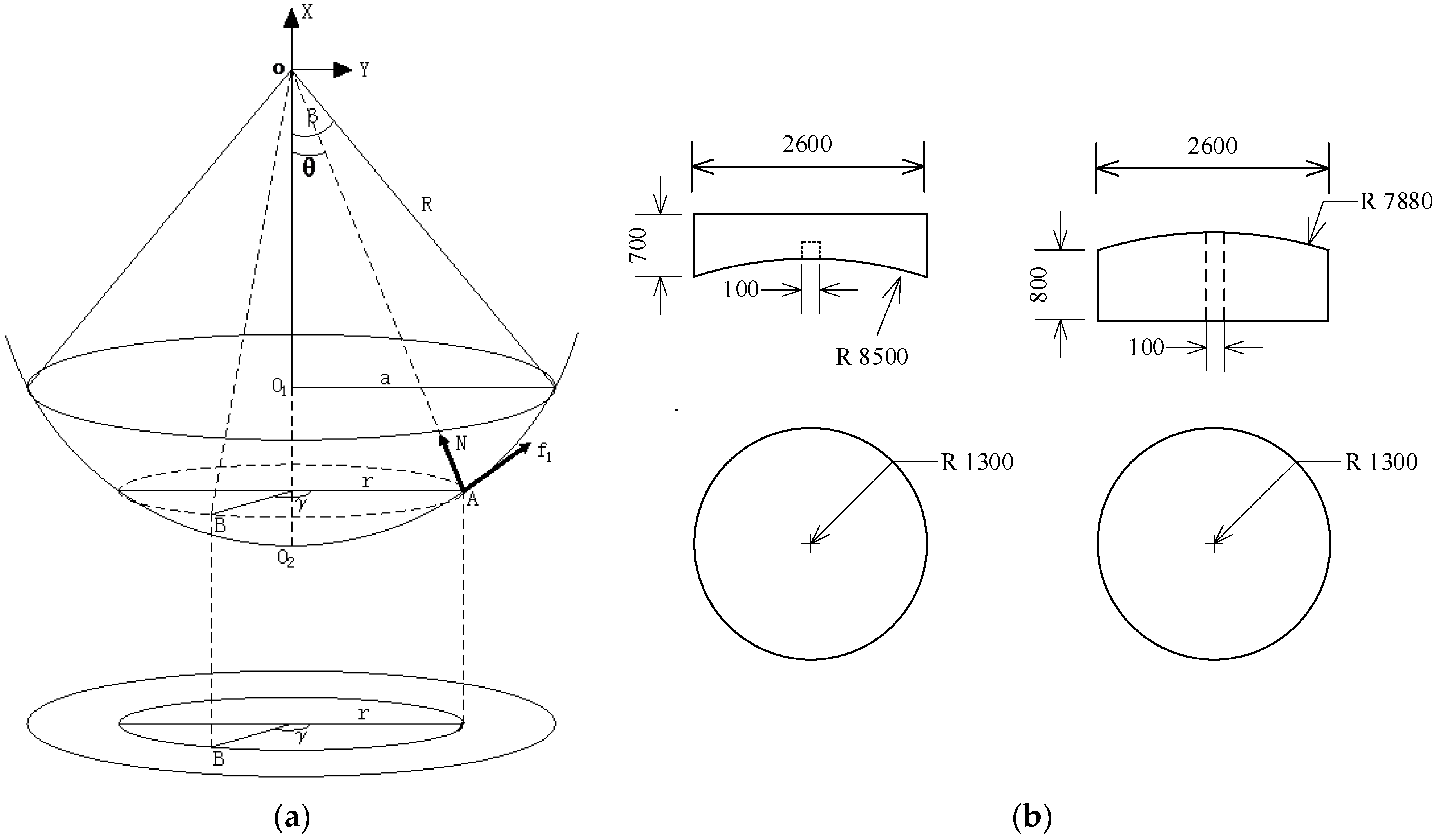
2.3. Construction Process of the Concrete Spherical Joint

An ordinary reinforced concrete spherical joint consists of upper and lower spherical joints. The surface of the lower spherical joint is made by the scraper tool, which is utilized to scrape the lower spherical joint repeatedly along the busbar before the final setting of concrete. In order to decrease the friction between the upper and lower spherical joints, they grind against each other to achieve identical surface morphology after the setting of concrete. Finally, special lubricant is smeared on the contact surface to reduce rotating friction.

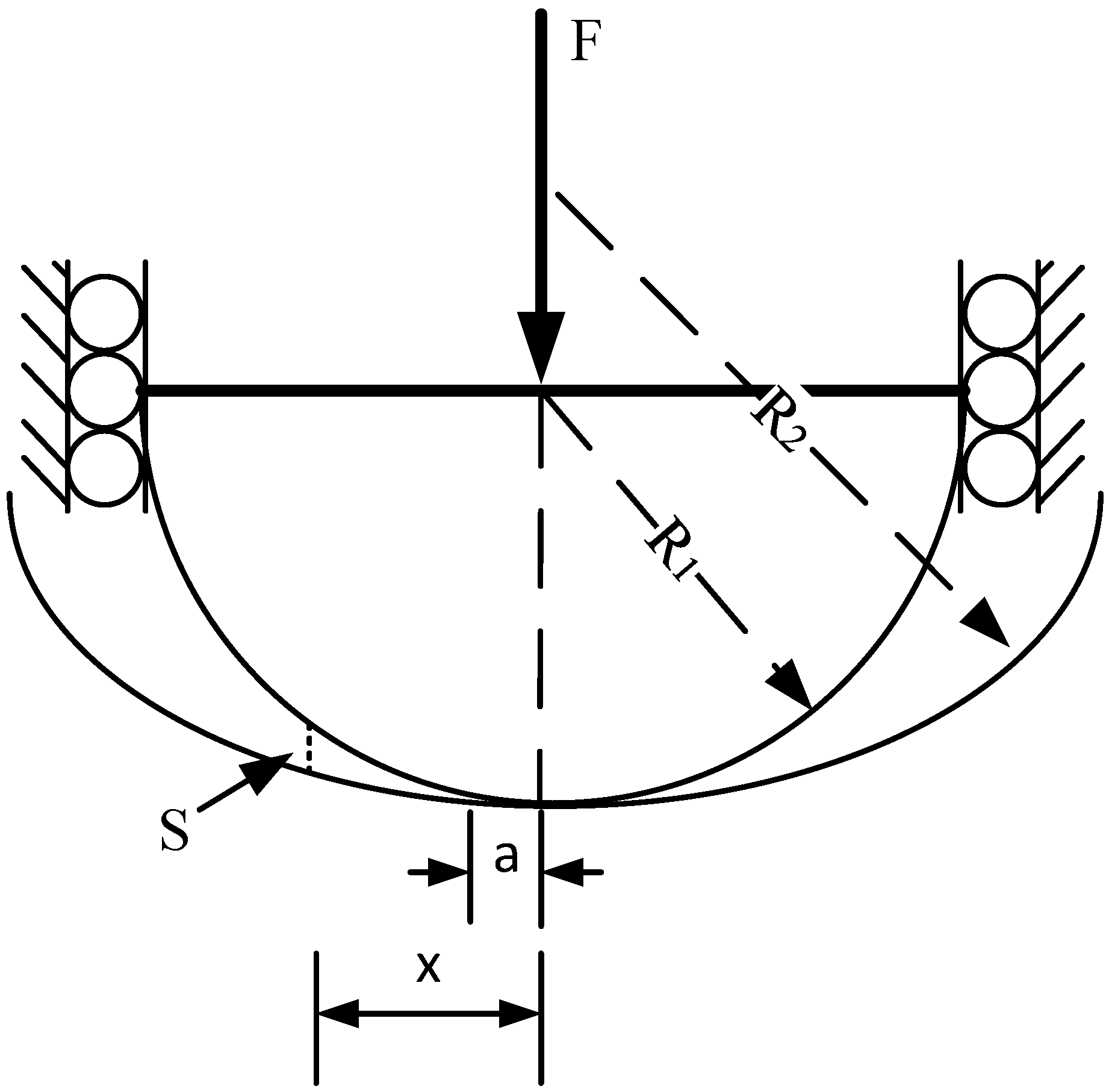
2.4. Non-Hertz Contact Theory of the Concrete Spherical Joint

The non-Hertz contact theory calculation model is suitable for conformal contact; therefore, the contact force of the upper and lower spherical joint can follow the law of non-Hertz contact theory [15,16]. The initial clearance of the axisymmetric structure (shown in Figure 4) is: S = A 1 x 2 + A 2 x 4 + + A n x 2 n + . Take the first two items; the other items can be ignored because they will not affect the results [17].
S = A 1 x 2 + A 2 x 4
where S is the distance between two contact surfaces and x is the distance of the contact border to the contact circle center. In Equation (1), A 1 and A 2 are quadratic parabolic coefficients.
For two-dimensional axisymmetric shapes in the form of A n x 2 n , the total load function and its pressure distribution curve are obtained [18]:
F n = 4 n E * A n a 2 n + 1 2 n + 1 · 2 · 4 · · 2 n 1 · 3 · · ( 2 n 1 )
p n ( x ) = n E * A n a 2 n 2 π · [ 2 · 4 · · 2 n 1 · 3 · · ( 2 n 1 ) ] 2 · { ( x a ) 2 n 2 + 1 2 ( x a ) 2 n 4 + + 1 · 3 · · ( 2 n 3 ) 2 · 4 · · ( 2 n 2 ) } ( a 2 x 2 ) 1 2
where F n is the total load, a is the contact bandwidth, E * is the equivalent modulus of elasticity, and A n is the coefficient of x 2 n .
1 E * = 1 μ 1 2 E 1 + 1 μ 2 2 E 2
A 2 = R 2 3 R 1 3 8 R 1 3 R 2 3
where E 1 and E 2 are the elastic modulus of two elastic bodies, respectively; μ 1 and μ 2 are the Poisson’s ratio of two elastic bodies, respectively; and R 1 and R 2 are the radii of the contact surfaces, respectively.
The resultant force F and stress distribution p ( x ) can be solved by using n = 2 with Equations (2) and (3).
F = 64 15 E * A 2 a 5
p ( x ) = 128 E * A 2 a 2 9 π · [ ( x a ) 2 + 1 ] · ( a 2 x 2 ) 1 2
Equation (6) can be rewritten, yielding the contact bandwidth a as:
a = 15 F 64 E * A 2 5

3. Cable Tension

3.1. Objective of Cable Tension

After the building procedure of the upper rotating table, back wall, and main arch, the weight of the main arch structure is not transferred to the position of the upper spherical joint [6]. The buckle cable and pulling cable are anchored alternately (Figure 5a), and are able to gradually transfer the weight of each part to the spherical joint position. The stages of cable tension are from a to k, which are shown in Figure 5. At stage a, the pulling cables are anchored. Then, the buckle cables are anchored at stage b. After stage a and b, the tension of pulling cables increases at stage c. Subsequently, the tension of the buckle cable increases at stage d. To prevent the cracking of the concrete back wall caused by too much tension in the cables, the tension of the pulling cables and buckle cables are increased alternately in the following stages of cable tension until stage k. The complete rotating system (Figure 5b) is formed by the construction procedure to ensure that the back wall concrete does not exceed the affordability of the tensile and compressive stresses.

3.2. Results of Cable Tension

During the cable tension process, the vertical displacement of the main arch must be monitored constantly. The vertical displacement monitoring positions are shown in Figure 6. The sensors for displacement testing were installed at every steel pipe welding position in our case study, because the joint position is the place where deformation is most likely to occur.
The results of the vertical displacements (No. 10, 19, 27, 36, and 38) during the cable tension stage are shown in Table 1. As can be seen, No. 19 had the largest vertical displacement during the cable tensioning process. This was due to the gravity and tensioning process bending the middle part of the arch. Special attention to the middle position of the main arch is recommended during the cable tensioning process.

4. Gravity Center Test

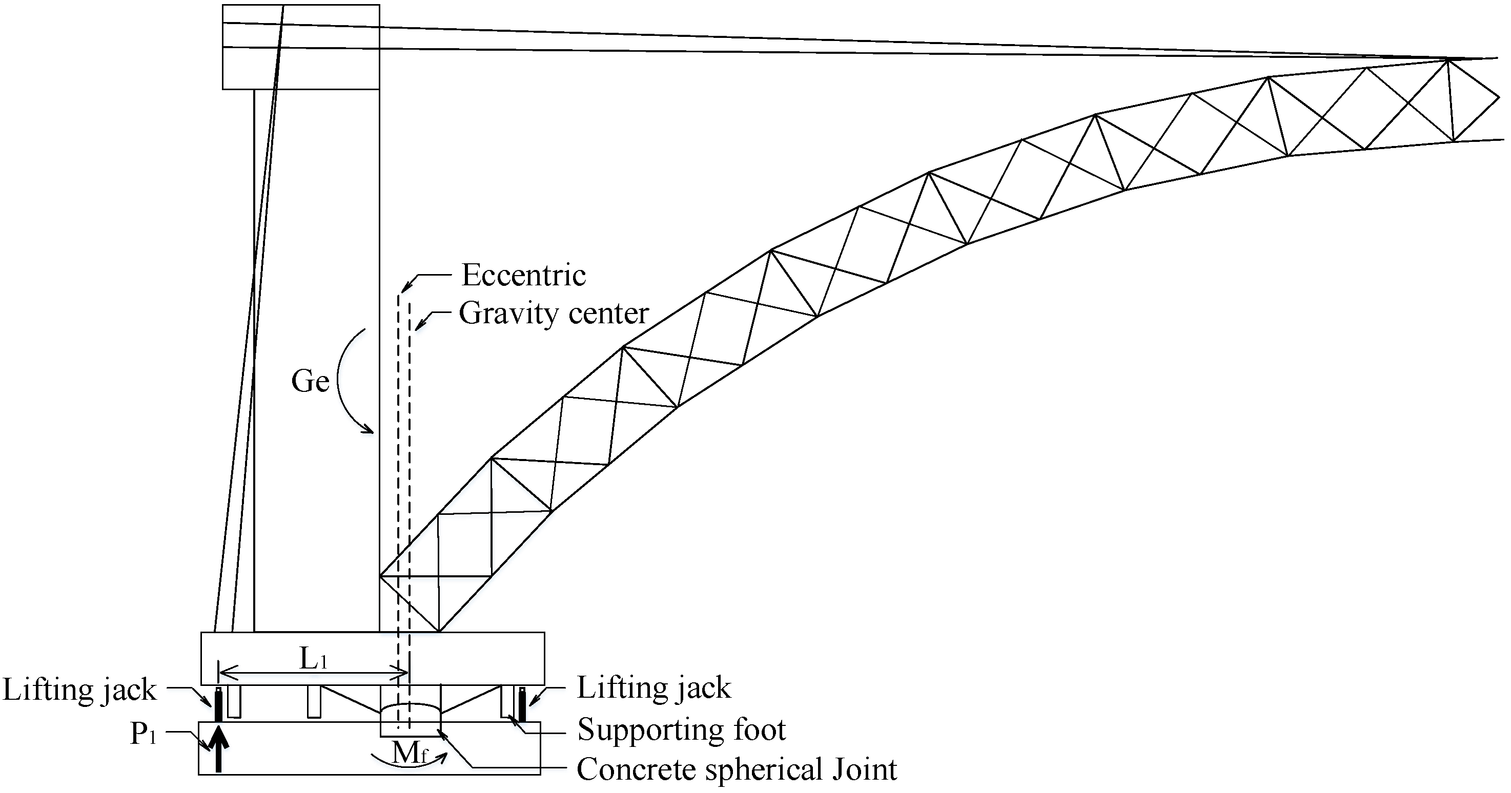
4.1. Mechanism of Gravity Center Test

4.1.1. Frictional Moment M f Larger Than the Unbalanced Moment M g

When M f > M g , there will be no rotation in the rotating system after the dismantlement of temporary constraint (cable system); therefore, the frictional moment of the spherical joint resists against the unbalanced moment of the rotating system, and the entire system stays in a stable state.
When the lifting force is increased on the left side, the static friction force of the rotating system becomes a dynamic friction force at a specific P 1 value. At this time, the lifting moment ( P 1 L 1 ) is equal to the sum of the friction moment ( M f ) and the unbalanced moment ( M g = G e ), and the spherical joint rotates instantaneously and slightly. Meanwhile, the data of the vertical and horizontal displacement sensors change instantaneously and significantly. Therefore, the lifting force P1 is increased to the maximum value. Here, the eccentric is supposed at the left side of the rotating system (Figure 7).
P 1 L 1 G e = M f
where P 1 is the lifting force of the spherical joint rotated instantaneously on the left side of the rotating system, L 1 is the arm of the lifting force, e is eccentric, G is the weight of the rotating system, and M f is the frictional moment.
When applying the lifting jack on the right side of the rotating system and increasing the lifting force, the static friction force of the rotating system becomes a dynamic friction force at a specific P 2 value. At this time, the lifting moment ( P 2 L 2 ) is equal to the sum of the friction moment ( M f ) and the unbalanced moment ( M g = G e ). The spherical joint rotates instantaneously and slightly. Just as before, the data of the vertical and horizontal displacement sensors change instantaneously and significantly. Therefore, the lifting force P2 is increased to the maximum value (Figure 8).
P 2 L 2 + G e = M f
where P 2 is the lifting force of the spherical joint rotated instantaneously on the right side of the rotating system, and L 2 is the arm of the lifting force.
Combining Equations (9) and (10):
e = P 1 L 1 P 2 L 2 2 G
M f = P 1 L 1 + P 2 L 2 2
M g = G e
μ = M f R G
where μ is the static friction coefficient and R is the radium of the spherical joint.
The traction force of the rotating construction according to the standard [19]:
T = 2 μ R G 3 D
where D is the arm of the traction force.

4.1.2. Frictional Moment M f Less Than the Unbalanced Moment M g

When M f < M g , the frictional moment of the spherical joint is not enough to resist against the unbalanced moment of the rotating system after the dismantlement of temporary constraint; therefore, the foot falls on the slideway are supported.
When the supporting foot is on the slideway, the lifting jack is applied only on the same side of the supporting foot (Figure 9). When the lifting force is increased, the static friction force of the rotating system becomes a dynamic friction force at a specific P 1 value. At this time, the lifting moment ( P 1 L 1 ) is equal to the sum of the friction moment ( M f ) and the unbalanced moment ( M g ). The spherical joint rotates instantaneously and slightly. Meanwhile, the data of the vertical and horizontal displacement sensors change instantaneously and significantly. Therefore, the lifting force P1 increases to the maximum value.
P 1 L 1 G e = M f
Continuing the test, the lifting force on the left side starts to decrease (Figure 10). Keeping the lifting force in the declining state, the dynamic friction force of the rotating system becomes a static friction force at a specific P value. At this time, the spherical joint rotates instantaneously and slightly. Just as before, the data of the vertical and horizontal displacement sensors change instantaneously and significantly. Therefore, the lifting force P decreases to the minimum value.
G e P L 1 = M f
where P is the declining lifting force of the spherical joint rotated instantaneously at the right side of the rotating system.
Combining Equations (16) and (17):
e = ( P 1 P ) L 1 2 G
M f = ( P 1 P ) L 1 2
The other parameters are the same as Equations (13)–(15).

4.2. Analysis of Engineering Results

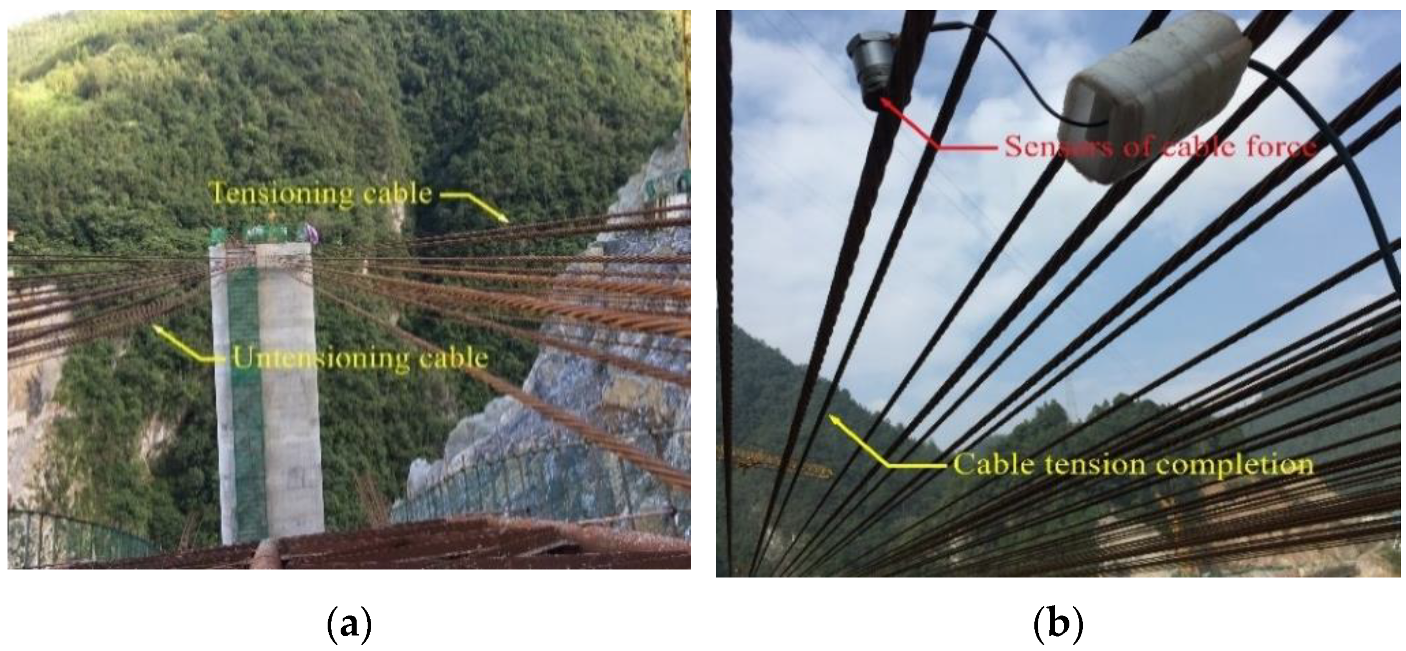
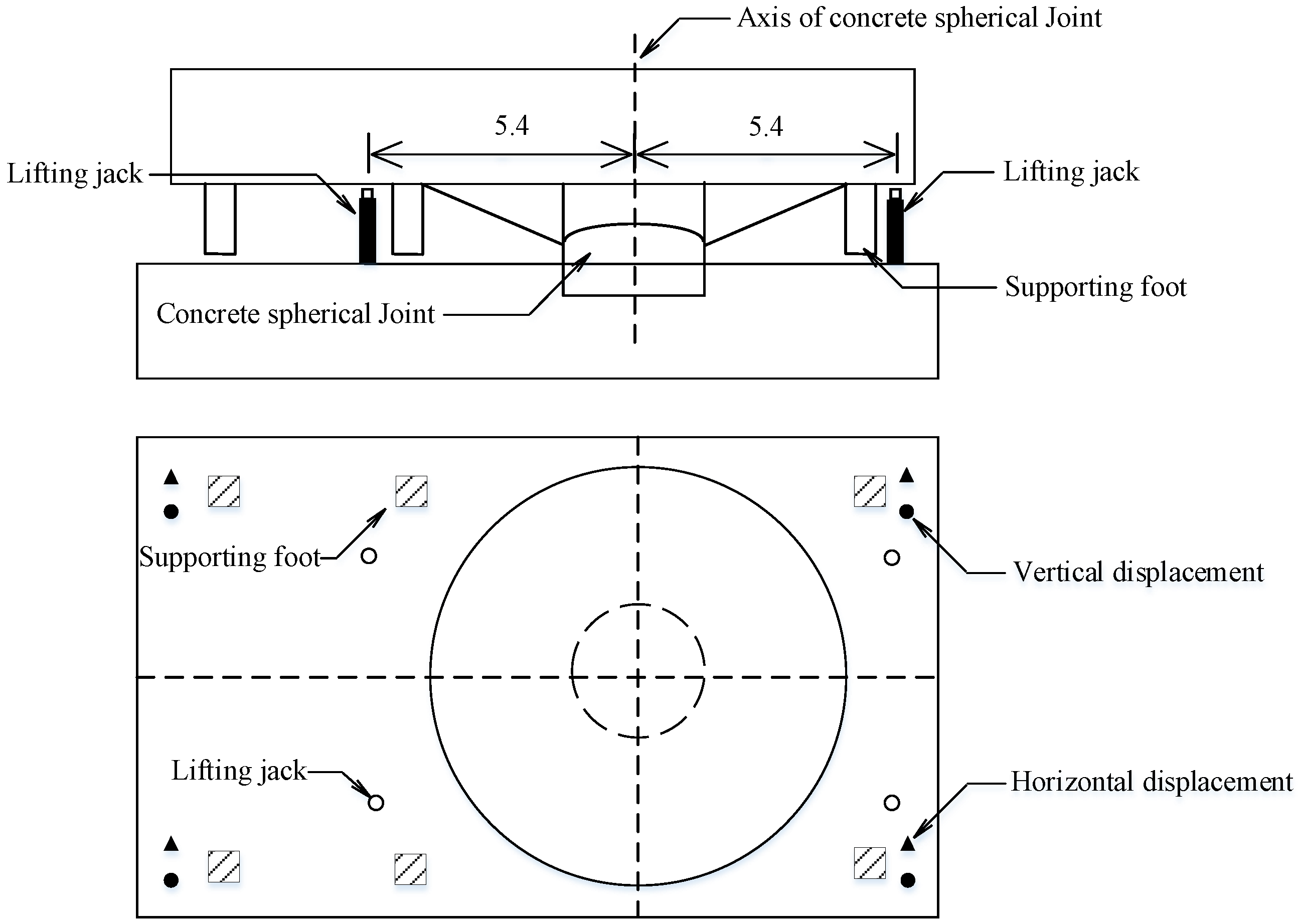
4.2.1. Measuring Sensors

In order to ensure the accuracy of the test results, the computer synchronous control lifting equipment was used in the gravity center test. The lifting force of two pieces of lifting equipment were controlled at the same time, and the displacement measurement was carried out to guarantee the accuracy of the test. The test equipment is shown in Figure 11.

4.2.2. Position of Sensors

The layout of the gravity center test instruments is shown in Figure 12. Four lifting jacks were placed on both sides of the bridge rotating system to test the critical load during the gravity center test. The maximum load of each lifting jack was 4000 kN.

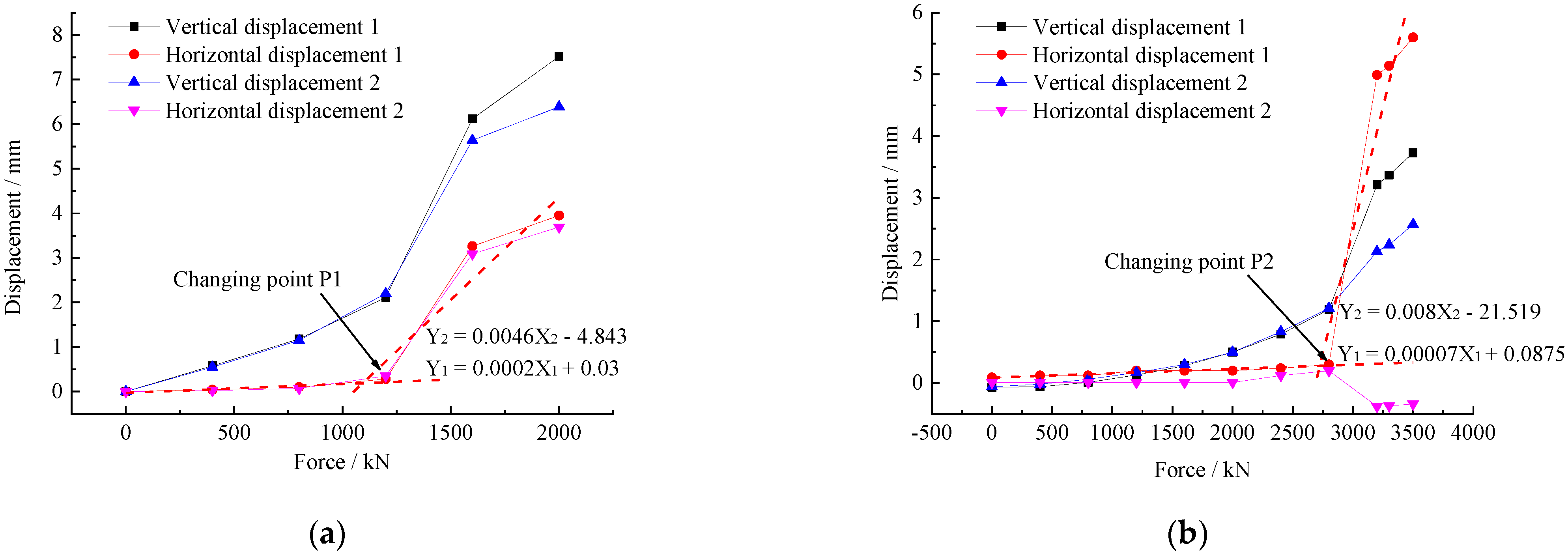
4.2.3. Gravity Center Test Results

When the temporary constraints of the rotating system were lifted all the dial indicator readings remained unchanged, i.e., the rotating system did not rotate, so it was known that the system belonged to the situation of M f > M g . The test results with the lifting jacks on both sides are shown in Figure 13.
As can be seen from Figure 13a, the abrupt change point value P1 of the main arch side during the lifting process was 1107.5 kN. As can be seen from Figure 13b, the abrupt change point value P2 of the back wall side during the lifting process was 2695.79 kN. We used Equations (9)–(15) to calculate the related parameters (shown in Table 2).

5. Stability Control of the Rotating Construction

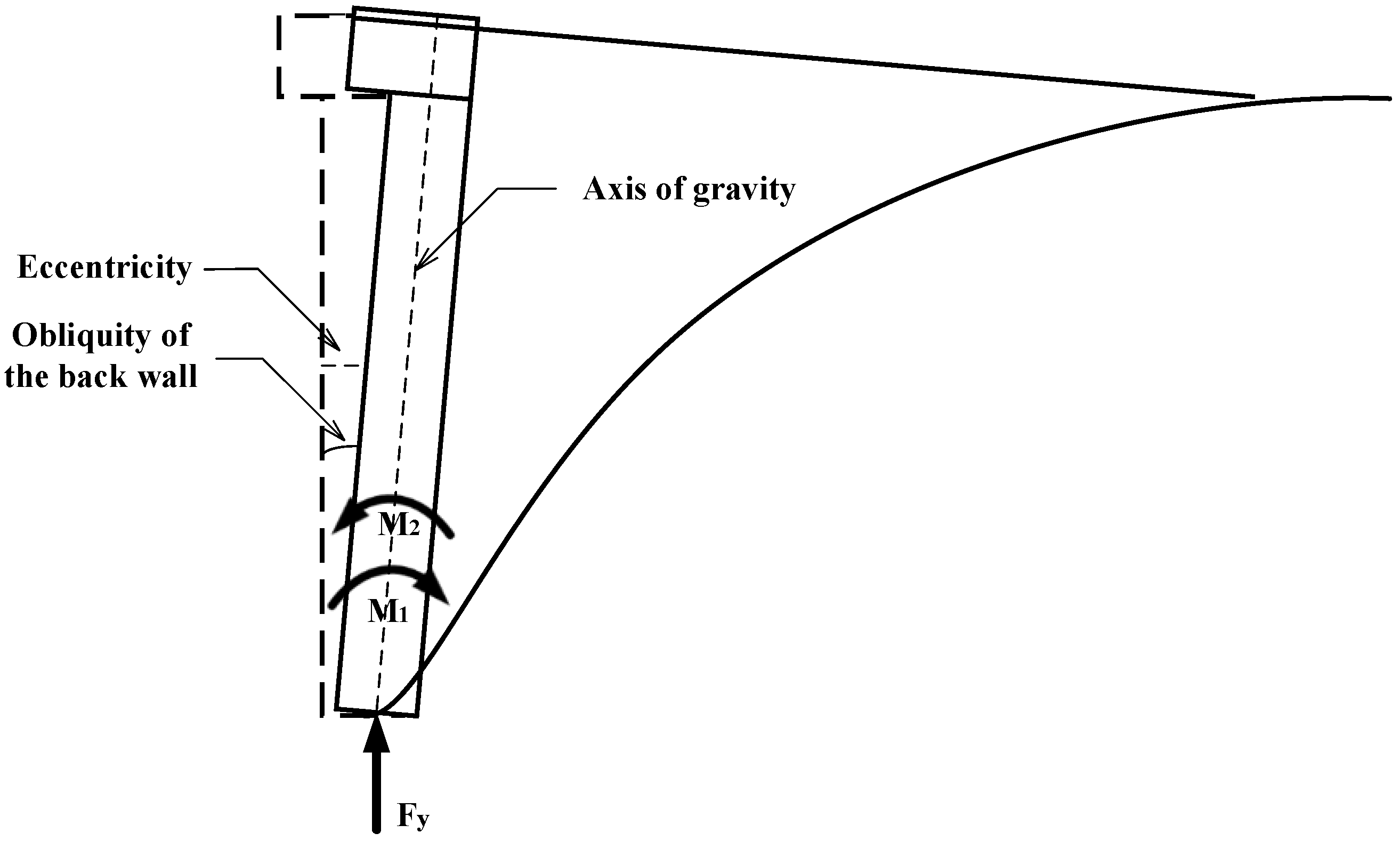
5.1. Overturning Moment of Rotating Construction

The eccentricity of the rotating system produces the overturning moment of the complete rotating system when the gravity center is not at the axis of the spherical joint center. Because the rotating process is the most crucial and dangerous step of the rotating bridge’s construction, the inclination of the rotating system should be monitored in real time while the rotating construction is in progress [20]. The change in obliquity angle can be used to track the rotating system’s overturning moment. Figure 14 depicts the relationship between the overturning moment and the slope of the back wall:
The overturning moment and rear-wall inclination angle are calculated using the following formula:
M 1 = G e
e = l sin δ
where M 1 is the overturning moment, M 2 is the resistance of the overturning moment, i.e., the frictional moment of the spherical joint, e is eccentricity, Fy is the supporting force, G is the gravity of the back wall, l is the center of gravity of the rotating system, and δ is the obliquity of the back wall.
As depicted in Figure 15, the swing bridge’s overturning resistance system consists of an annular slideway, several supporting feet, and a locating pin. The overturning resistance moment is generated by the friction moment of the spherical joint when the rotating bridge’s supporting foot is not in contact with the ground. When the supporting foot touches the ground, the rotating system’s overturning resistance capacity reaches its apex, and the supporting foot functions as the last barrier in the overturning resistance system.

5.2. Formula Deduction of Overturning Moment Resistance

Figure 16a depicts the spherical joint’s geometry and the size of the spherical joint is presented in Figure 16b.
There is microfrictional resistance f 1 on micro plane A, which can be estimated as follows:
d f 1 = μ σ d s
where d s = R 2 sin θ d θ d γ and μ is the friction coefficient. Therefore:
d f 1 = μ σ R 2 sin θ d θ d γ
The overturning moment M 2 has a resistance of:
d M 2 = L d f 1 = L μ σ R 2 sin θ d θ d γ
where L is the overturning arm; for each micro plane L = ( R cos θ ) 2 + ( R sin θ sin γ ) 2 ; and Equation (7) is:
σ = 128 E * A 2 a 2 9 π · ( x 2 + y 2 a 2 + 1 ) · ( a 2 x 2 y 2 ) 1 2
where x 2 + y 2 = r 2 = ( R sin θ ) 2 . Therefore:
σ = 128 E * A 2 a 2 9 π · [ ( R sin θ a ) 2 + 1 ] · ( a 2 ( R sin θ ) 2 ) 1 2
The whole bridge resistance of the overturning moment is:
M 2 = μ α β 0 2 π 128 E * A 2 a 2 9 π · [ ( R sin θ a ) 2 + 1 ] · ( a 2 ( R sin θ ) 2 ) 1 2 · ( R cos θ ) 2 + ( R sin θ sin γ ) 2 sin θ d θ d γ
In which, α is the smallest spherical joint size (the boundary of locating pin) and β is the largest spherical joint size of the radius of the spherical joint for contact bandwidth.

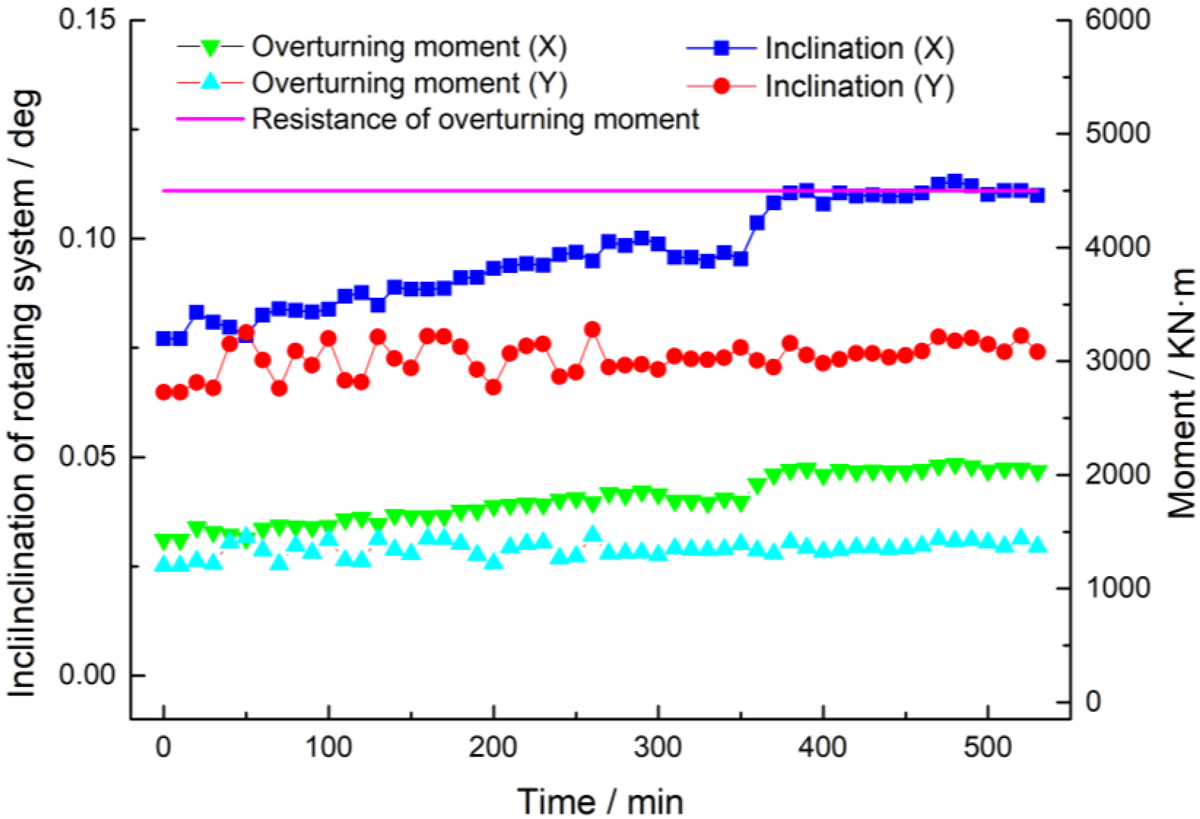
5.3. Inclination Analysis of Rotating Construction

The inclination tracking system is arranged on the rotating system of the Nandu River Swing Bridge to track the changes in the inclination angle of the back wall during the rotating process and to judge the changes in the overturning moment of the rotating system in real time. When the inclination angle of the rotating system is too large, the inclination angle of the rotating system can be corrected in real time to ensure the safety, stability, and smoothness of the rotating system. The lifting jacks are placed at the lower rotating table to lift and correct the inclination of the rotating system. The parameters of the rotating system are shown in Table 3.
The upper and lower limits of θ are α = Arcsin(50/8500) and β = Arcsin(1300/8500), respectively. The spherical joint R = 8500 mm, and the contact bandwidth a = 1300 mm. Changing all of the parameters in Equation (26), the resistance of the overturning moment M 2 = 4499.79 kNm is calculated using the Mathematica program.
The back wall’s inclination angles X (along the bridge) and Y (across the bridge) are determined. Equations (20) and (21) are used to compute the back wall’s overturning moment in the X and Y directions. Figure 17 depicts the results:
The largest inclination angle appears in 0 during 480 min of the rotating construction. The maximum overturning moment is calculated using Equations (20) and (21), and the maximum value of our case study was 2094.38 kNm, which was less than the resistance of the overturning moment. As a result, the rotating system stayed safe during the rotating construction process.

6. Recommendations for Practice

The present study exhibits the whole process of rotating construction. The following recommendations are proposed for practical construction:
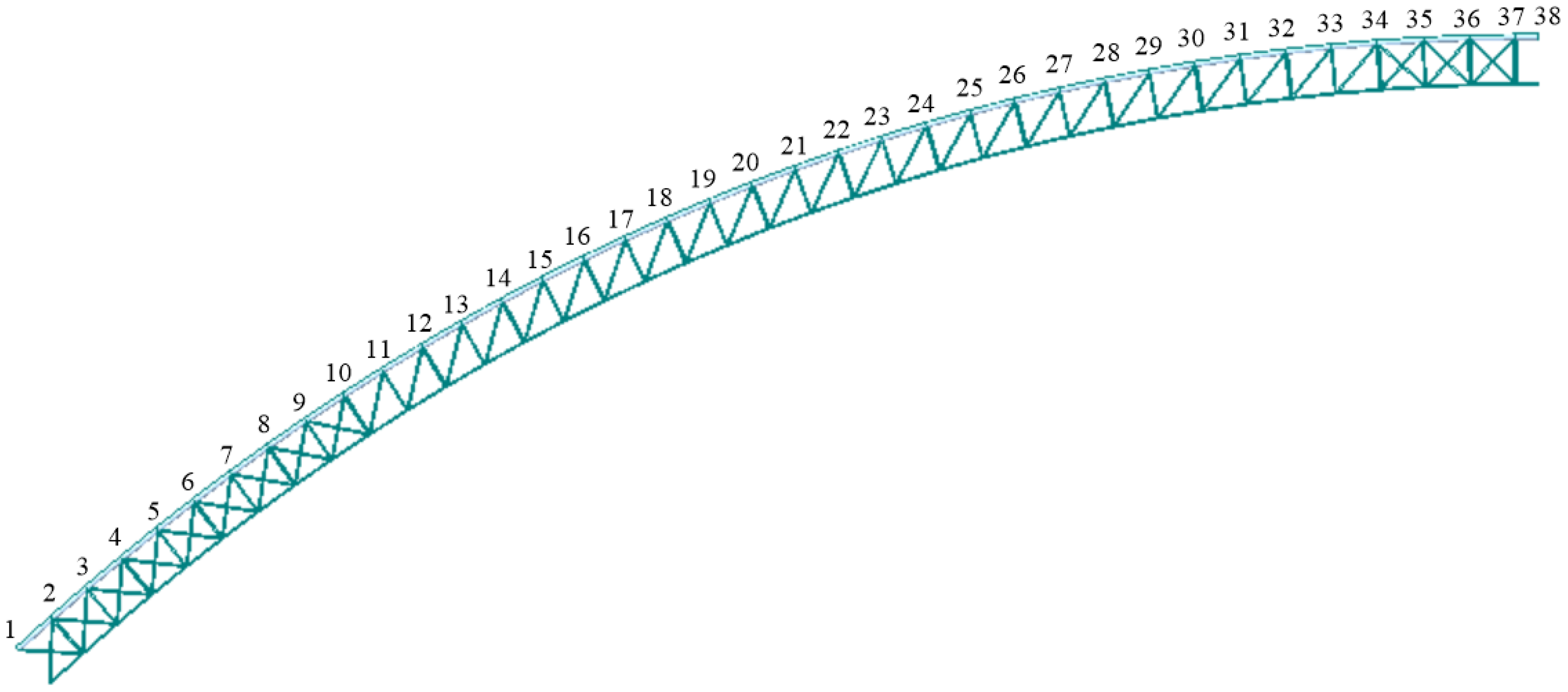
  • The arch rib can be entirely removed from the frame after the cable tension stages. However, the deformation of the main arch, especially vertical deformation, is obvious during the cable tension period. Therefore, the linear changes to the main arch throughout the tensioning process must be continuously monitored. This guarantees the linear shape of the main arch after cable tension, achieving the aim of structural safety;
  • During the gravity center test, the displacement of the upper rotating table has to be monitored continuously in real time. The lifting process by the lifting jack should stop immediately once the changing point appears. This prevents the overload of the lifting jack resulting in the overturn of the rotating system;
  • The inclination of the rotating system should be tracked in real time during the rotating construction of the main arch. The stability of the rotating system entirely depends on the fractional moment of the spherical joint. Thus, the central load-bearing state of the rotating system is significant to decrease the overturning moment.

7. Discussion and Conclusions

The rotating construction of swing bridges has traditionally faced the problem of achieving a central load-bearing state. The monitoring process of rotating construction is critical, as it is related to the safety of the bridge construction. With increasing amounts of bridge construction in mountainous areas, research into swing bridges needs to be thoroughly explored. The entire process of the rotating construction of swing bridges has never been fully reported. Moreover, it is important to offer an example of rotating construction for clarity, in order to ensure the safety of swivel construction.
In this study, the complete construction process of the swing bridge is presented to give an insightful overview of its key problems. All of the involved processes aim to bring the bridge construction to a central load-bearing state. During the cable tension stage, the middle of the main arch can reach 162.3 mm in vertical displacement. This might trigger structural buckling. This can be controlled by monitoring the cable tension. Furthermore, there is the risk of the fractional moment being smaller than the unbalanced moment shown by the gravity center test results. Ideally, the overturning moment reaches its maximum value at 2094.38 kNm during the rotating process, as this is smaller than the overturning resistance (fractional moment). The whole monitoring process of the swivel construction has been presented. The central load-bearing state is emphasized to safely control swivel construction.
The greatest advantage of this study is that it predicts the possible risks that could occur during swivel construction. By utilizing the following solutions, the safety of swivel construction can be ensured and a central load-bearing state can be achieved. As noted above, the following conclusions can be drawn.
  • The non-Hertz contact theory can be properly utilized to calculate the spherical joint stress distribution. It can be used to reach central load-bearing control when calculating the surface contact stress distribution of the spherical joint;
  • Special attention to the middle position of the main arch is recommended during the cable tensioning process, since this is the most dangerous position during the procedure;
  • The key problem of the gravity center test is to determine the changing point during the lifting process, as this is the most important process before the rotating construction. It enables the balance of the rotating system to be established, guaranteeing load-bearing control;
  • Overturning moments are monitored by the inclination tracking system and calculated by the deduced formula based on the non-Hertz contact theory. This guarantees the safety of the rotating construction.

Author Contributions

Conceptualization, T.L. and J.F.; formal analysis, T.L.; funding acquisition, J.F.; methodology, T.L.; project administration, J.F.; writing—original draft, T.L.; writing—review and editing, J.F. and Z.P. All authors have read and agreed to the published version of the manuscript.

Funding

This research received no external funding.

Institutional Review Board Statement

Not applicable.

Informed Consent Statement

Not applicable.

Data Availability Statement

The data presented in this study are available from the first author upon reasonable request.

Conflicts of Interest

The authors declare no conflict of interest.

References

  1. Zhang, C.; Wen, J.; Han, Q.; Du, X.; Lai, Z.; Fu, G. Transverse seismic response of diamond-shaped pylon in cable-stayed bridge: Experiment and analysis. Eng. Struct. 2022, 250, 113414. [Google Scholar] [CrossRef]
  2. Liu, T.; Fan, J.; Peng, Z.; Liu, Z. Modified Algorithm of Anchor Cable Force in a Suspension Bridge Based on the Cable-beam Composite Structure. J. Highw. Transp. Res. Dev. 2020, 14, 38–44. [Google Scholar] [CrossRef]
  3. Zheng, J.; Wang, J. Concrete-Filled Steel Tube Arch Bridges in China. Engineering 2018, 4, 143–155. [Google Scholar] [CrossRef]
  4. Fuchs, N.; Tomlinson, K.; Buckby, R. El Ferdan Bridge, Egypt: The world’s longest swing bridge. Bridg. Eng. 2003, 156, 21–30. [Google Scholar] [CrossRef]
  5. Griggs, F.E. American swing bridges 1797 to 1907. Pract. Period. Struct. Des. Constr. 2011, 16, 170–185. [Google Scholar] [CrossRef]
  6. Li, W.; Huang, C.; Tang, C. Negative angle vertical rotating construction method of reinforced concrete arch bridge. Struct. Eng. Int. J. Int. Assoc. Bridg. Struct. Eng. 2017, 27, 558–562. [Google Scholar] [CrossRef]
  7. Liang, D.; Yao, C.; Liu, S. Structural type selection for long-span bridges in mountain area. Appl. Mech. Mater. 2013, 256–259, 1596–1600. [Google Scholar] [CrossRef]
  8. Liu, T.; Yu, Q.; Fan, J.; Peng, Z.; Wang, E. Concrete spherical joint contact stress distribution and overturning moment of swing bridge. Structures 2020, 28, 1187–1195. [Google Scholar] [CrossRef]
  9. Ye, X.W.; Xia, P.S.; Su, Y.H.; Chen, B. Analysis and probabilistic modeling of wind characteristics of an arch bridge using structural health monitoring data during typhoons. Struct. Eng. Mech. 2017, 63, 809–824. [Google Scholar] [CrossRef]
  10. Li, Q.H.; Wang, X.Y.; Han, L.L. Analysis on vertical swivel construction of cable-stayed bridge with steel arch pylon. Appl. Mech. Mater. 2014, 477–478, 635–639. [Google Scholar] [CrossRef]
  11. Alocci, C.; Valvo, P.S. Feasibility study of a hybrid FRP-steel cable-stayed pedestrian swing bridge. Eng. Struct. 2019, 189, 359–372. [Google Scholar] [CrossRef]
  12. Sun, Z.; Hao, C. Conformal Contact Problems of Ball-socket and Ball. Phys. Procedia 2012, 25, 209–214. [Google Scholar] [CrossRef] [Green Version]
  13. Liu, T. Research on the Key Problems of Concrete Sphere Hinge in the Rotating Construction of Long-Span Bridge. Master’s Thesis, Wuhan University of Technology, Wuhan, China, 2018. (In Chinese). [Google Scholar]
  14. Watanabe, E.; Maruyama, T.; Tanaka, H.; Takeda, S. Design and construction of a floating swing bridge in Osaka. Mar. Struct. 2000, 13, 437–458. [Google Scholar] [CrossRef]
  15. Fang, X.; Zhang, C.; Chen, X.; Wang, Y.; Tan, Y. A new universal approximate model for conformal contact and non-conformal contact of spherical surfaces. Acta Mech. 2015, 226, 1657–1672. [Google Scholar] [CrossRef]
  16. Fan, J.F.; Liu, T.; Peng, Z.Q.; Liu, Z.; Yin, Y.X.; Sheng, Y.Q. Stress Distribution Analysis of Sphere Hinges of Swing Bridge Based on Non-Hertz Contact Theory. Wuhan Ligong Daxue Xuebao/J. Wuhan Univ. Technol. 2018, 40, 48–52. [Google Scholar] [CrossRef]
  17. Fagan, M.J.; McConnachie, J. A review and detailed examination of non-layered conformal contact by finite element analysis. J. Strain Anal. Eng. Des. 2001, 36, 177–195. [Google Scholar] [CrossRef]
  18. Liu, C.S.; Zhang, K.; Yang, L. Normal force-displacement relationship of spherical joints with clearances. J. Comput. Nonlinear Dyn. 2006, 1, 160–167. [Google Scholar] [CrossRef]
  19. JTG/T F50-2001; Technical Specification for Construction of Highway Bridge and Culvert. China Communications Press Co., Ltd.: Beijing, China, 2011.
  20. Quaranta, G.; Marano, G.C.; Trentadue, F.; Monti, G. Numerical study on the optimal sensor placement for historic swing bridge dynamic monitoring. Struct. Infrastruct. Eng. 2014, 10, 57–68. [Google Scholar] [CrossRef]
Figure 1. (a) Rotating system and rotating construction process; (b) spherical joint.
Buildings 12 00511 g001
Figure 2. The layout of the Nandu River Swing Bridge (unit: m).
Buildings 12 00511 g002
Figure 3. Construction process (a) main arch construction; (b) cable tension; (c) rotating process; (d) closure of main arch; (e) pier and deck construction.
Buildings 12 00511 g003aBuildings 12 00511 g003b
Figure 4. Sketch for analyzing the conformal contact joint with clearance.
Buildings 12 00511 g004
Figure 5. (a) Cable tension stage; (b) cable tension measurement.
Buildings 12 00511 g005
Figure 6. Vertical displacement monitoring position.
Buildings 12 00511 g006
Figure 7. Lifting force on the left side of the rotating system.
Buildings 12 00511 g007
Figure 8. Lifting force on the right side of the rotating system.
Buildings 12 00511 g008
Figure 9. Lifting force on the left side of the rotating system.
Buildings 12 00511 g009
Figure 10. Lifting force on the right side of the rotating system.
Buildings 12 00511 g010
Figure 11. (a) Lifting system; (b) displacement sensors.
Buildings 12 00511 g011
Figure 12. Position of the sensors.
Buildings 12 00511 g012
Figure 13. (a) Force–displacement curve of the main arch side; (b) force–displacement curve of the back wall side.
Buildings 12 00511 g013
Figure 14. Overturning moment calculation.
Buildings 12 00511 g014
Figure 15. Resistance system of the overturning moment. R is the radius of spherical joint; R’ is the plane radius of spherical joint; α is the angle of the outer edge of the spherical joint; θ is the angle of the spherical joint.
Buildings 12 00511 g015
Figure 16. (a) The geometry of spherical joint; (b) upper (left) and lower (right) spherical joints (unit: mm).
Buildings 12 00511 g016
Figure 17. The rotating system’s inclination and overturning moment.
Buildings 12 00511 g017
Table 1. Vertical displacement of the cable tension stage.
Stage of Cable TensionCable Force/kNDisplacement of the Top Back Wall
(Horizontal: mm)
Displacement of Main Arch
(Vertical: mm)
Pulling CableBuckle Cable1019273638
a11,0000.3−22.30.0−0.9−1.3−1.80.7
b10,600250020.00.0−0.4−0.8−1.10.4
c31,5002500−20.10.0−0.4−0.8−1.10.4
d31,500500022.20.00.0−0.2−0.50.0
e43,5005000−1.30.00.0−0.2−0.50.0
f43,500649023.926.680.978.99.6−5.2
g49,500650012.427.182.180.09.8−5.3
h49,500714023.248.9133.8128.815.8−8.4
i52,500715017.549.2134.4129.415.9−8.4
j52,500750023.460.9162.3155.819.210.1
k52,540758024.860.2156.9141.310.142.2
Table 2. Calculation results of the rotating system.
ParametersValueUnitNote
L5.4mLifting arm
P22695.79kN
P11107.5kN
G59,600kN
R8.5mSpherical radius
Unbalanced moment Mg4291.2kN·m
Friction moment Mf10,268.883kN·m
Eccentric e0.072mDeflect to back wall
Table 3. Factors of the rotating system.
FactorsFrictional Coefficient μThe Height of GravityGravitation of the Rotating System
0.117.802 m59,600 kN
Publisher’s Note: MDPI stays neutral with regard to jurisdictional claims in published maps and institutional affiliations.

