1. Introduction
The tunnelling industry is constantly evolving. From the time of ancient civilisations to the present day, builders and engineers have always sought to apply new technologies to this age-old art [
1]. The 19th century saw the great explosion of the tunnelling industry with the development of the railways. The 20th century saw the consolidation of drilling and blasting methods, and the end of the century saw a revolution in the sector with the advent of tunnel-boring machines. Today, both TBMs and the machinery needed to bore tunnels, according to the New Austrian method (NAM), incorporate a wealth of sensors and automation technology that make it possible to execute tunnels with performance and safety conditions that were unimaginable only a few years ago. Moreover, the increasing digitization of information surrounding the design, construction, and operation of underground works is currently one of the main catalysts towards the transformation of the sector [
2].
In recent times, it is already a fact that building information modelling (BIM) methodology is transforming the architecture, engineering, and construction professions [
3,
4]. BIM is a collaborative working methodology for the creation and management of construction projects with the main objective of centralising all the relevant project information in a digital information model created by all its stakeholders.
There is no longer any doubt that BIM is progressively transforming building and civil engineering projects above ground, although the current uses are mainly for visualizing projects in 3D and for detecting collisions between different disciplines [
5]. However, its use in projects related to underground works is still residual [
6,
7,
8], and it is precisely in these type of projects with high investment, great technical complexity, and a high cost in case of error, where this collaborative work methodology can find its maximum application.
This article describes the use of the BIM methodology in the execution of the Arnotegi tunnel in the extension of the Bilbao South Metropolitan Bypass. The case described is an example of the application of the BIM methodology in a complex project in which, in addition to the traditional uses, an attempt has been made to advance in methodology, concentrating the information, both from the project and that generated during the work in a common data environment linked bidirectionally with the model, to facilitate the flow of information in real time for all those involved, favouring decision-making and ensuring execution times and their associated costs.
This article is organised as follows: The first part includes the state of the art and the main previous references on the use of the BIM methodology in underground construction works. Subsequently, the Arnotegi tunnels project, the main stakeholders, and the adopted contractual scheme are described. Finally, the article details the specific system of implementation of the BIM methodology and the obtained results.
2. Background
The dream of managing all the tunnel information in a structured database is not new. The first relevant precedent in our environment is the TUNCONSTRUCT project (Technology Innovation in Underground Construction, funded between 2005 and 2009 within the framework of the European Research Area). This project aimed to transform the European underground construction industry into a high-tech, high value-added industry capable of providing innovative, sustainable, and cost-efficient solutions [
9].
The backbone of the project consisted of the definition of an underground construction information system (UCIS) that would allow the recording and instant access to all tunnel data throughout the entire life cycle, from the design and construction stage to the in-service stage (
Figure 1). At the time, this UCIS system was based on the latest database technology available and based its need on the fact that more and more data was being produced by different parties and sources. In addition, the project was aware that there was a demand to access all data from anywhere, at any time, although this situation was far from the reality at the time of its development [
10].
Since then, the TIAS (tunnel information and analysis system) project was launched in Greece, which consisted of the generation of a database integrating 62 tunnels on the Egnatia motorway. The data contained came from different sources: boreholes, geotechnical surveys, laboratory tests, geological behaviour, hydrogeology, design parameters, support and lining information, construction incidents, and costs. This system was intended to structure all the accumulated knowledge to provide engineers with valuable information when designing new tunnels in massifs similar to the one in the area examined [
11].
The initiatives described refer to the most relevant attempts to date to generate structured bases for organising the information surrounding the construction of the tunnel. To make this data even more valuable, the technology is now mature enough to be fully integrated into the methodological concept of BIM, although so far there are very few references of significant use in underground works and generally referred to case studies [
7,
12].
In recent years, there are references in the literature that have specifically addressed conceptual frameworks based on the BIM methodology to improve the management of underground projects using the drill-and-blast method [
13].
In the execution of the Arnotegi tunnel, it has been possible to contribute to this leap in the integration of the BIM methodology, where it has been able to reveal its full potential, both as an instrument and as a procedure.
It should be noted that this transition is taking place in an environment in which, despite the specificities of tunnel projects, there are no standards at the European level for their design, let alone harmonised guidelines for the use of the BIM methodology. At the European level, the design and management of tunnels is developed on the basis of national knowledge and experience, with the use of design standards imposed by each client. In 2017, the European Commission initiated the setting up of a commission to define the needs for standardisation in the design of underground infrastructures with particular emphasis on tunnels [
14]. In this context, the most advanced country in the digitisation of underground space, in line with its overall progress in the use of the BIM methodology, is likely to be the United Kingdom. The UK has some of the most agile and adapted standardisation systems for working with digital images of underground space. A national geospatial data strategy was adopted in 2020, which contains a special section on digital subsurface information [
15].
3. The Case. Description of the Underground Works: The Arnotegi Tunnel
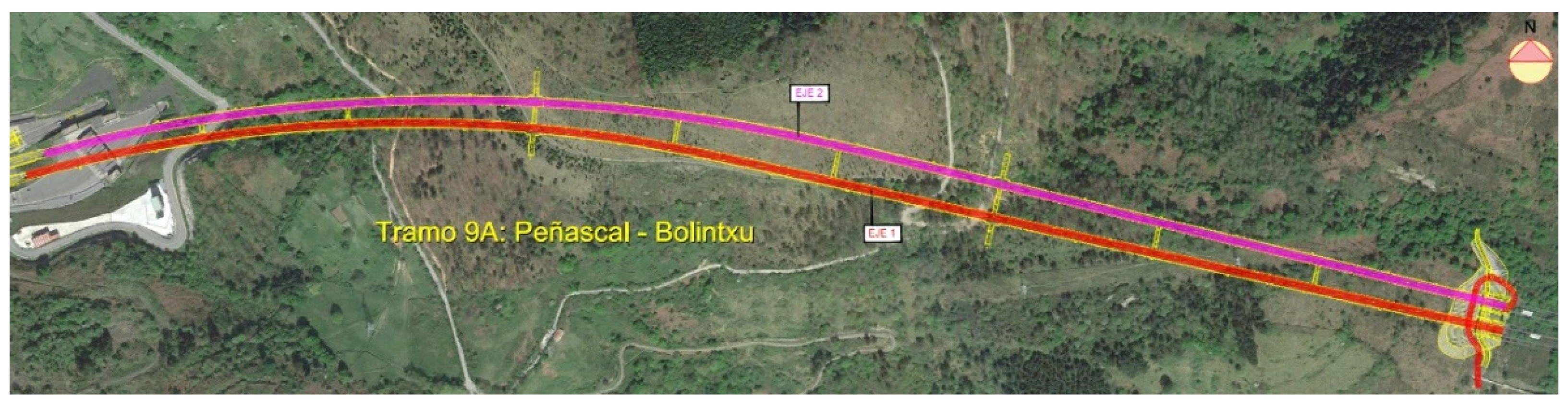
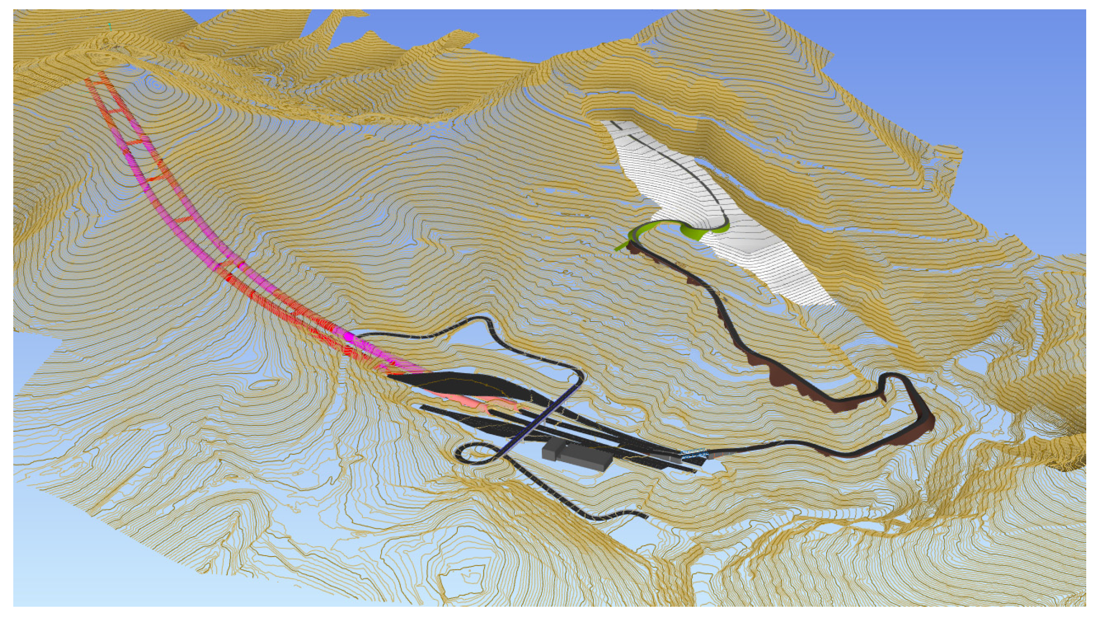
The construction of the Arnotegi tunnel (
Figure 2) is included in the works of the so-called Section 9A of the infrastructure of Phase IA of the Bilbao Southern Metropolitan Bypass, promoted by Interbiak-Provincial Council of Biscay. It is one of the three sections of the next expansion phase, which aims to connect the original bypass, inaugurated in 2011, with the AP-68 motorway [
16].
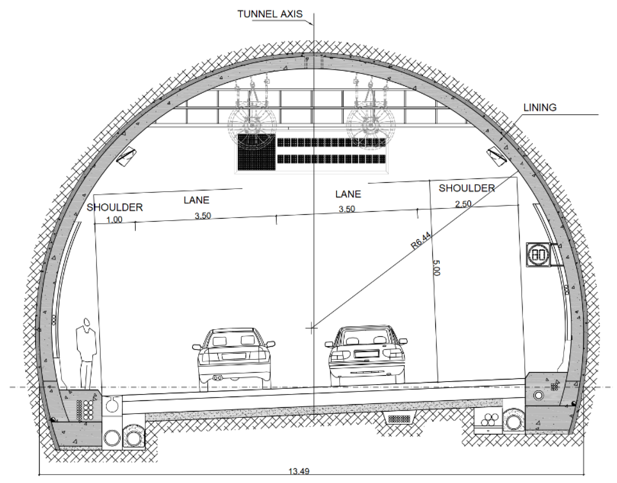
The area of the works is located in the municipality of Bilbao, Spain. The Arnotegi tunnel is a double-road tunnel, with one tube for each direction of traffic. The length of the tunnel in the mine corresponding to the carriageway in the Cantabria direction (Axis 1) is 1727 m, while the length of the tunnel in the mine excavated for the carriageway in the Donostia direction (Axis 2) is 1722 m. The tunnel has a truncated circular cross section, with an internal section of 85 m
2 (
Figure 3), and its main characteristics are shown in
Table 1.
From a geological point of view, the Arnotegi tunnel runs through Cretaceous rocky terrain made up of siltstone with sandstone levels and with no significant water inflow. The tunnel was excavated using the drill-and-blast method, except in particular cases such as gallery intersections where mechanical excavation was used. According to the geotechnical specific characteristics of the excavated materials, five types of support were designed, including different amounts of bolts, shotcrete, and metallic trusses.
4. Main Actors and Proposed Contractual Model
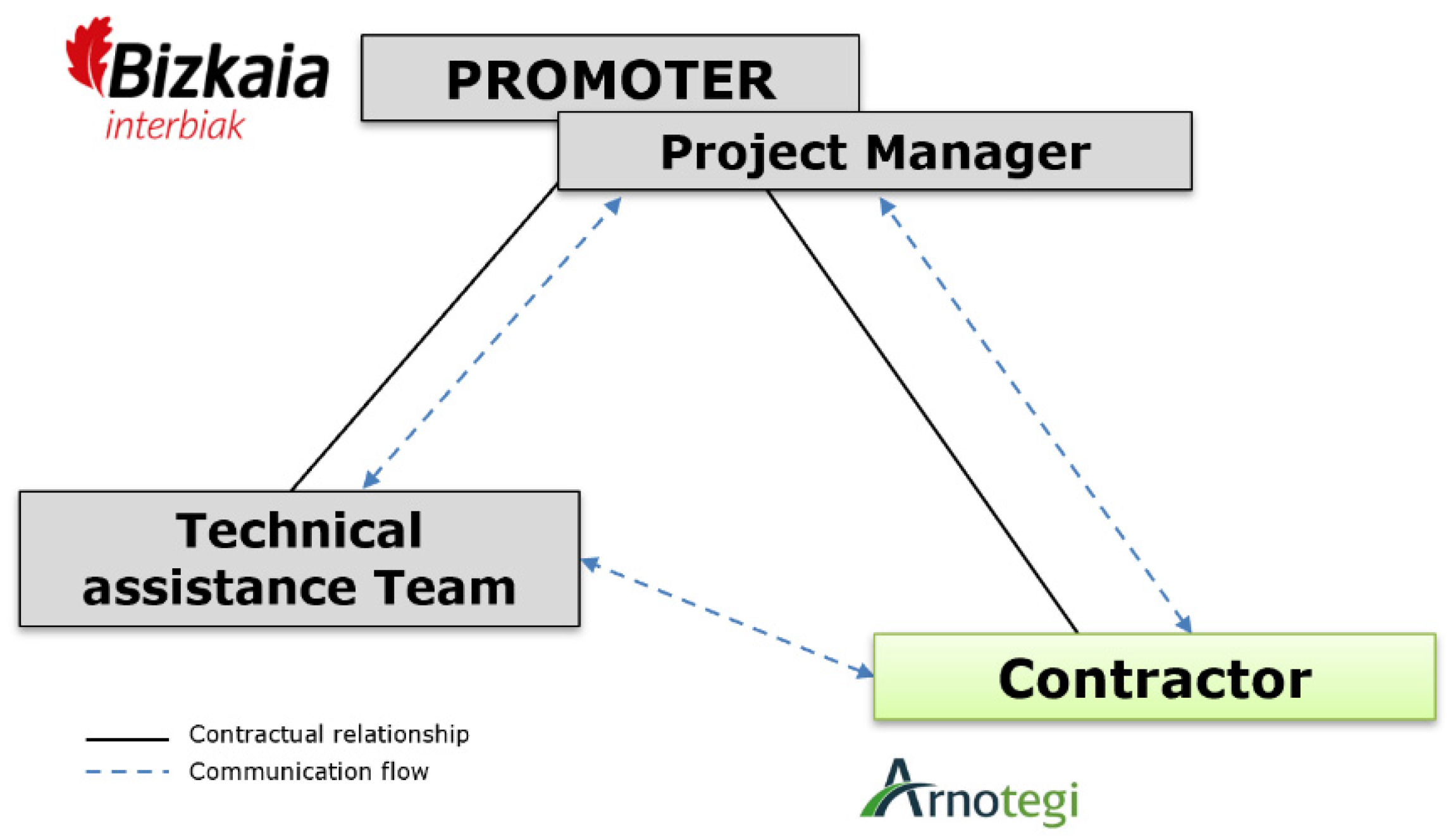
The main parties involved follow the usual pattern for infrastructure projects at the national level. The promoter of the works is also the project manager. This public authority independently hires the contractor and the technical assistance team to carry out the works (
Figure 4).
This traditional contracting scheme can be an impediment to seeking maximum collaboration between the parties involved, which is a real necessity for the successful implementation of the BIM methodology [
17], as each agent naturally tends to develop its activity within the exclusive framework of its contract. To guarantee maximum collaboration between the parties involved, the works contract includes two relevant aspects in this respect. Firstly, the specific administrative terms and conditions define that the prescribed remuneration system is the lump-sum method. Secondly, the contract is complemented by the specific technical specifications, which in Appendix 9 establishes a series of innovative actions that must be complied with by the successful bidder. The development of the works forms part of the object of the contract itself, and therefore, the costs are understood to be included in the flat-rate offer for the overall execution of the work.
The aforementioned Appendix 9 established several innovative proposals that had to be implemented during the course of the contract. These innovative proposals include the implementation of the BIM methodology. The following section describes the particularities of the implementation of this work methodology in the Arnotegi tunnel.
5. Description of the Proposed System Using BIM Methodology
Appendix 9 of the specific technical specifications of the contract indicated as a contractual service the implementation of the BIM methodology, understood as the “preparation and development of coordinated and collaborative databases and information models with a view to improving the integration and coherence of the information throughout the life cycle of the asset”. The main contractual requirement was to deliver at the end of the infrastructure works a BIM model of the Arnotegi tunnel, which included all the relevant elements of the tunnel construction, including graphic and non-graphic information, which will facilitate the coordination tasks with subsequent contracts and the subsequent operation and maintenance tasks of the infrastructure (
Figure 5).
5.1. BIM Execution Plan
During the first months of execution of the contract, the BIM execution plan (BEP) was drawn up, a document that defined the bases, standards, and rules for working with this methodology. The BEP developed in detail the basic principles indicated in the specifications so that all those involved in the work could carry out their work in a coherent and coordinated manner. The document had a living character of continuous improvement that evolved throughout the construction process, adapting to new needs and always maintaining the objective of achieving a practical and useful BIM implementation.
It is worth highlighting three concepts that have been considered the most important within the BIM implementation plan because of the advantages they provide. On the one hand, in terms of workflows, it established the basis for deploying the collaborative environment by defining a folder structure for the entire project, a homogeneous document-coding system and the roles, permissions, and responsibilities of each user in the common data environment (CDE). This aspect is very important because the CDE of this project is not focused exclusively on storing and working with the BIM models, but all the information of the project is stored in it.
On the other hand, if we focus on the 3D models, the interference matrix made it possible to reduce the number of collisions at an early stage of the project and the organisation of the parameters ensured that the intended uses could be achieved, and the models were ready for the exploitation phase.
Finally, the third most relevant aspect of the BEP has been the definition of a specific codification for the processing of the work. This coding has allowed the bidirectional link between the 3D models and the documentation of the work stored, also thanks to the capabilities of the CDE platform used. This concept responds to what is known as an integrating model and allows quality control of the stored documentation as well as the availability of the most important information for each asset in the exploitation phase.
5.2. BIM Uses and Models
Table 2 shows, in order of priority, the intended BIM uses, both in the development of the Arnotegi tunnel project itself and in the subsequent operation phase.
To achieve the uses defined in the table above, three main BIM models were developed: an initial model, an updated model, and a follow-up model, which was updated periodically throughout the works.
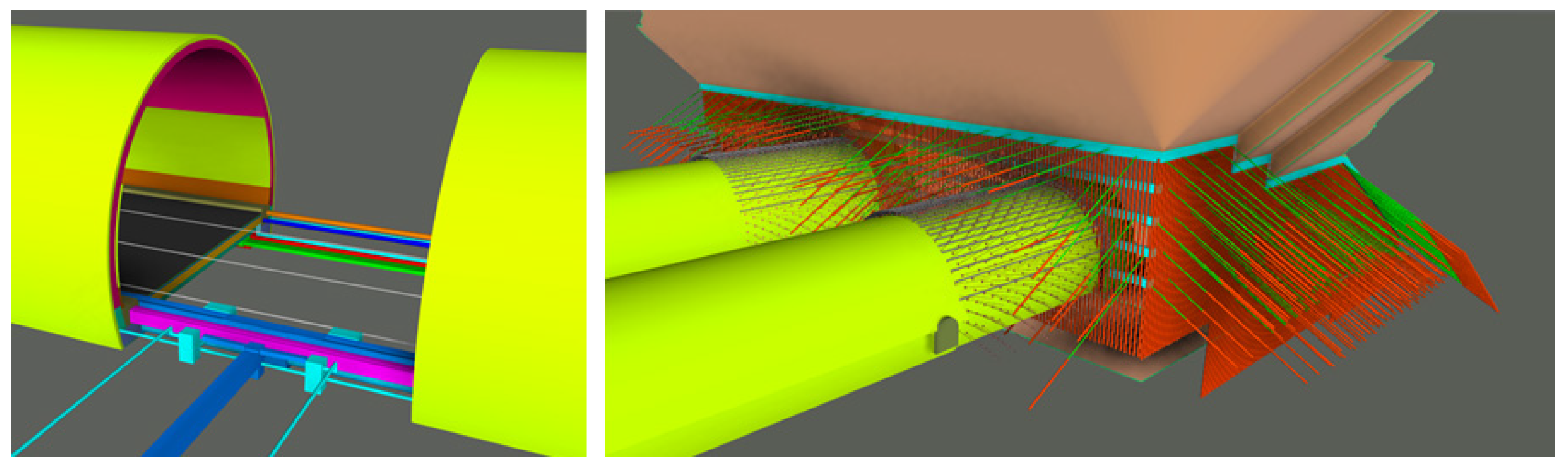
The main uses of the initial model (
Figure 6), which was based on the two-dimensional project provided by the promoter, consisted of a 3D design, detection of interferences (
Figure 7), and analysis of possible solutions to these interferences in a collaborative manner during the meetings held using the models.
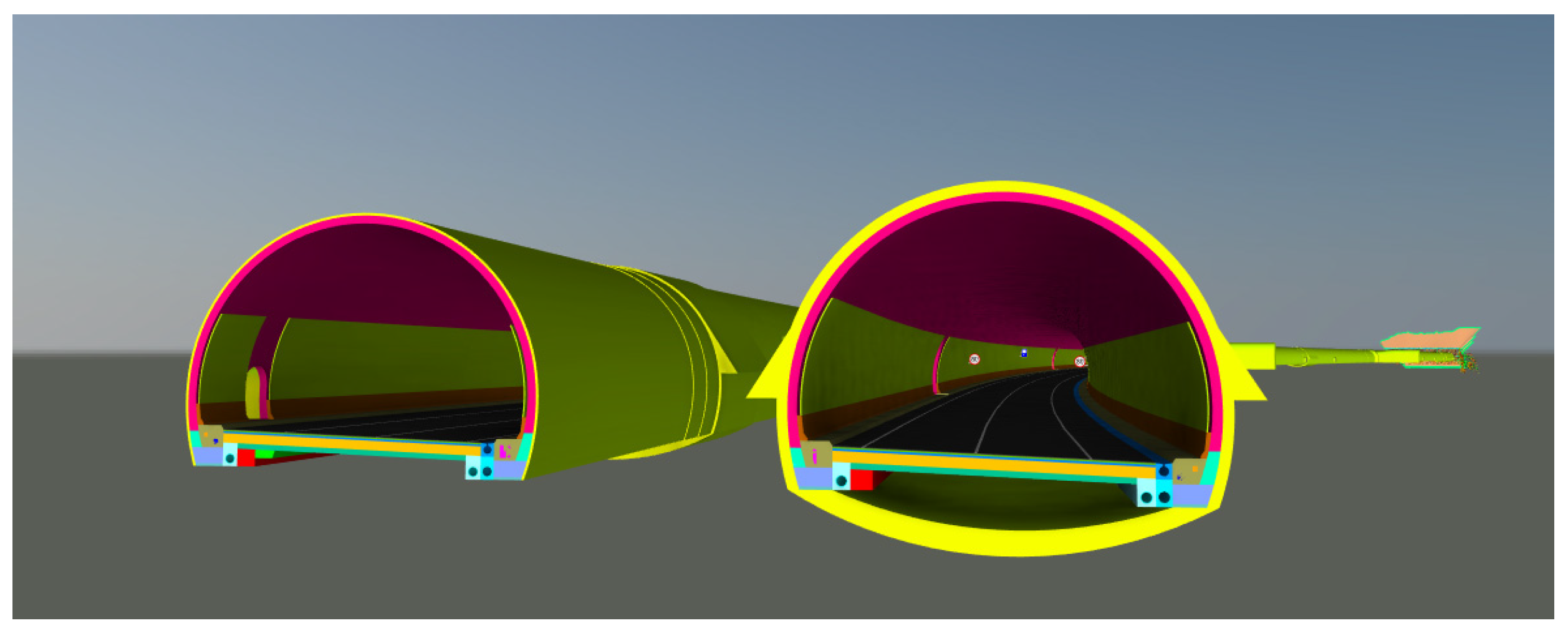
In the second phase, the updated BIM model was developed (
Figure 8), whose main uses consisted of coordinating the 3D design, not only between disciplines, but also with the rest of the project lots, 4D planning, and being the reference base for the construction process by including the resolution of each of the discrepancies identified in the initial model.
However, one of the most relevant uses of this model and the common data environment arose from the need to use the most up-to-date information possible for the design of the project for the execution of the facilities. Permission was granted to the successful bidders of this contract to access the model and the most up-to-date information necessary, thus minimizing possible future discrepancies and therefore contributing efficiency and great value to the concept of “collaboration” for which the BIM methodology is characterized.
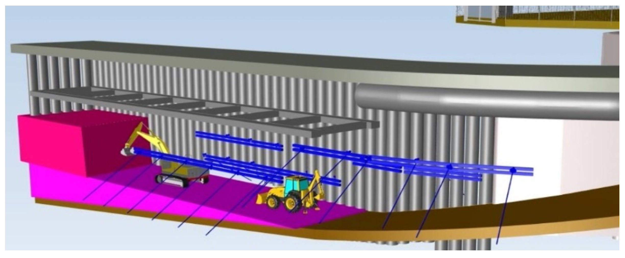
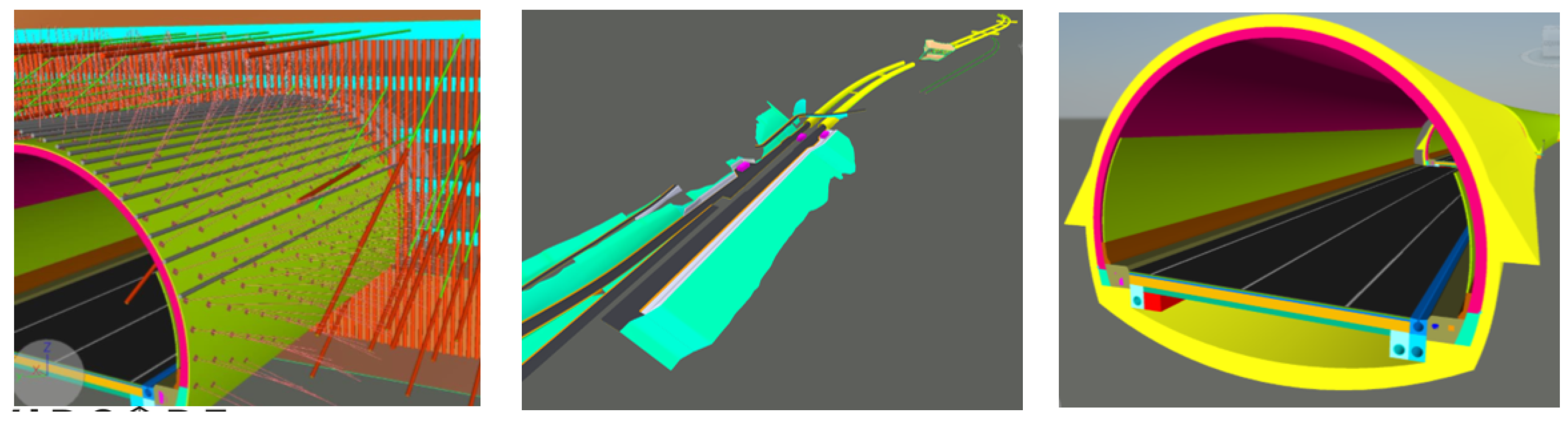
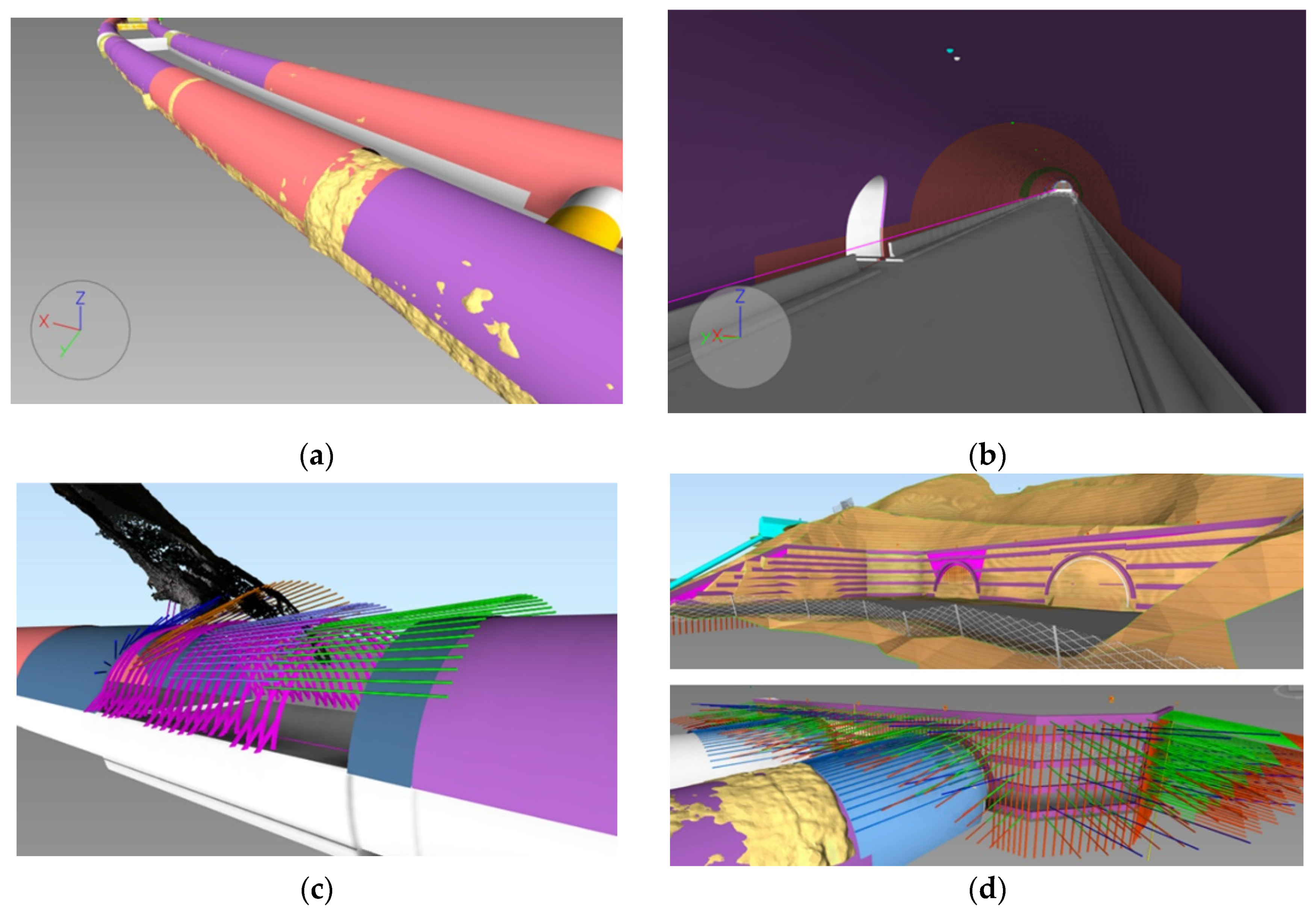
Finally, during the execution of the works, progressive as-built modelling was carried out according to the real progress. The main uses of this follow-up model consisted, on the one hand, of its geometric control (tolerances in each tunnel advance step and section entry), the integration of new control geometries, such as sensors and other auscultation devices, and even support in the analysis of alternatives to special treatment solutions for the tunnel (
Figure 9). The follow-up model was updated 126 times during the duration of the works on a weekly basis.
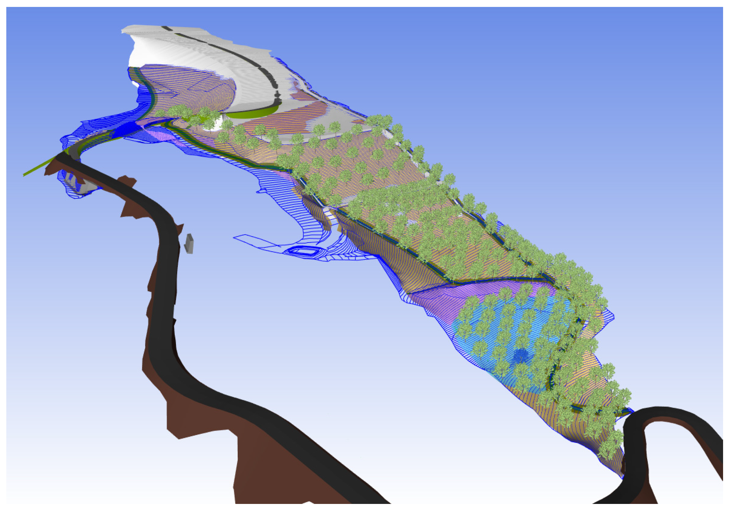
In addition, a detailed monitoring of the sowings and the evolution of the landfill site has been carried out, allowing an intuitive visualisation of the state of the revegetation of each of the areas (
Figure 10).
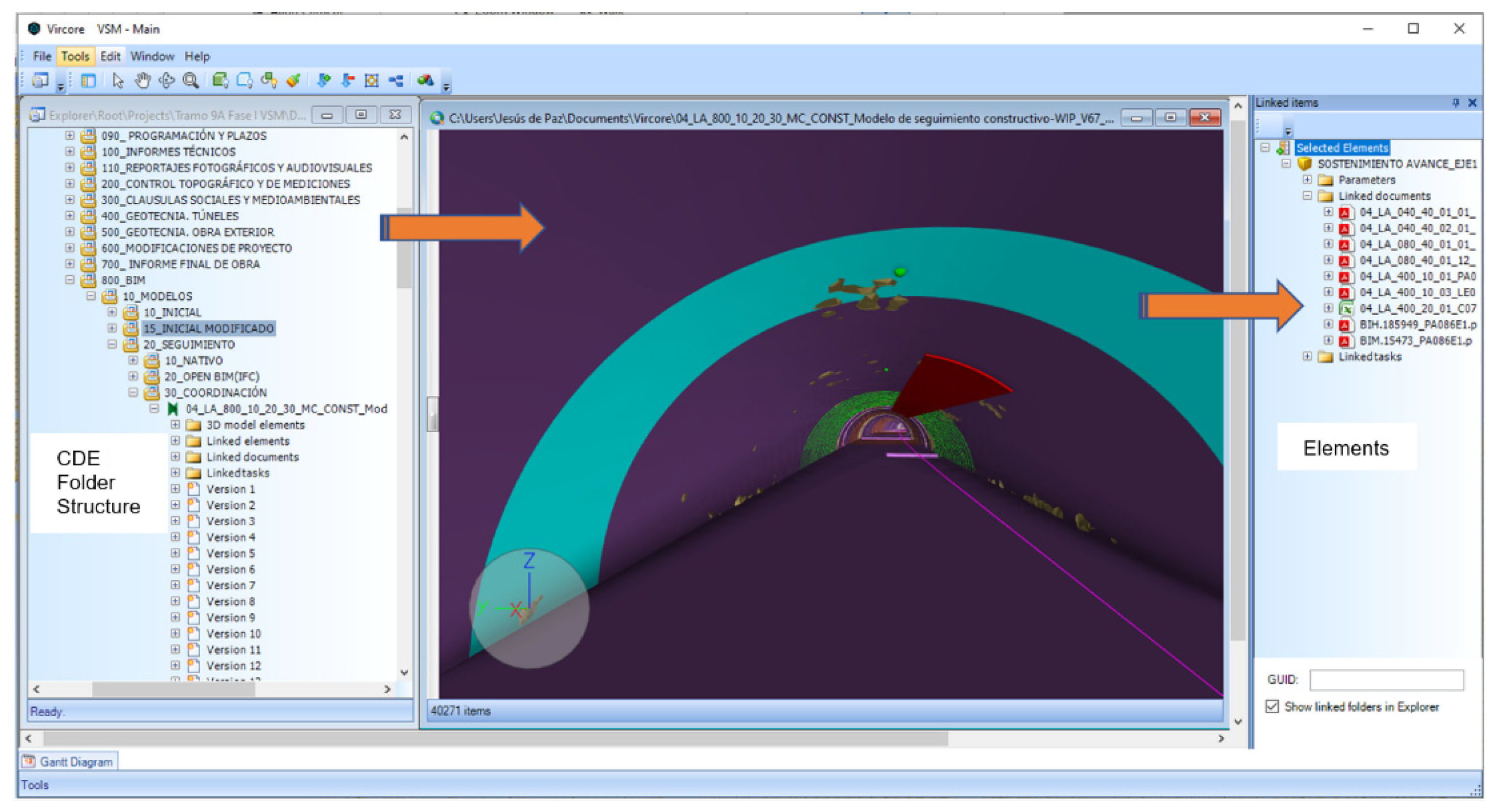
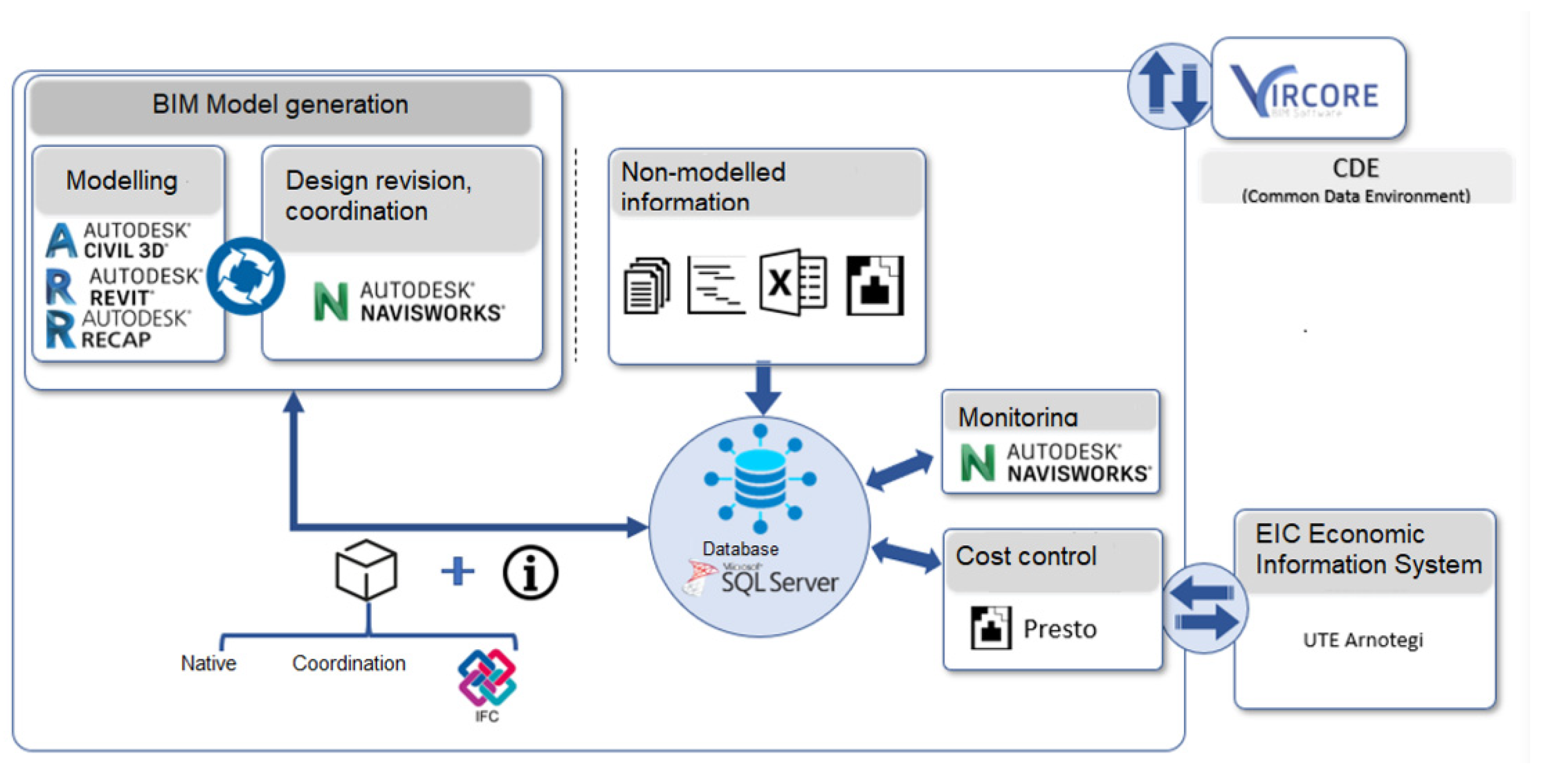
Besides, one of the most relevant uses during this phase has been the integration of the information generated during the construction process. The technology used as a collaborative environment (CDE), Vircore [
18], has allowed all the documentation stored in the document manager to be linked automatically and bidirectionally to each 3D element, guaranteeing that any type of information, regardless of its location in the folder structure, is accessible from the 3D BIM model as long as it is related to the selected 3D element (
Figure 11).
5.3. Level of Graphic Detail
According to the customer’s requirements, the level of detail (LOD) for all modelled elements is LOD 300, considering that for the as-built final models, the corresponding and achieved LOD is LOD 500.
LOD 300 is the level at which all the tunnel elements (support passes, support elements, and other tunnel elements) are graphically defined, precisely specifying their shapes, sizes, quantities, and locations in relation to the project as a whole. These elements can be observed in detail. They always have a graphical representation and may contain non-graphical information as well.
5.4. Common Data Environment
5.4.1. Multi-Project Document Management
The global management of the project was carried out using Vircore software [
18], developed by Ingecid S.L. This software allows the management through a user interface of this database and the storage container, facilitating the various operations required throughout the project.
Once the folder structure of the common data environment had been defined and agreed upon by all those involved, its component elements were defined. On the one hand, there were a series of digital models of the different disciplines that were associated in a coordination model for their review and modification, if necessary, and on the other hand, there were all the non-modelled information that were generated in the different phases of the construction project that could be linked to the different modelled elements if their relationship allowed it, as well as stored within the common data environment.
All this information (modelled and non-modelled) stored centrally allowed the monitoring of the work to be carried out in an integrated and efficient manner.
5.4.2. Model Visualization
Vircore either allows for the use of its own built-in viewer for the management of IFC files or for the use other viewers, such as the Navisworks Manage graphic engine that ensures the visualisation of models developed in multiple native formats.
5.4.3. 4-D Planning and Quantity Survey
Vircore can integrate the rest of the needs related to BIM models without requiring the use of external tools. In this sense, it has an integrated planning module that allows multiple planning without the need for other software. It also features bidirectional communication with MS Project if necessary.
In this case, the strong point of Vircore is in the linkages; the tasks can be bidirectionally linked to the 3D elements of the models, allowing the visualisation and management of interactive 4D simulations, and on the other hand, the planning can be associated with documentation for the project phases where it is necessary (preparation of reports, memories, etc.).
Vircore allows the integration of files in BC3 format, and as with schedules, it allows for the development of budgets and their work breakdown structure (WBS) from scratch.
5.5. Procedure for Linking Information to the Model
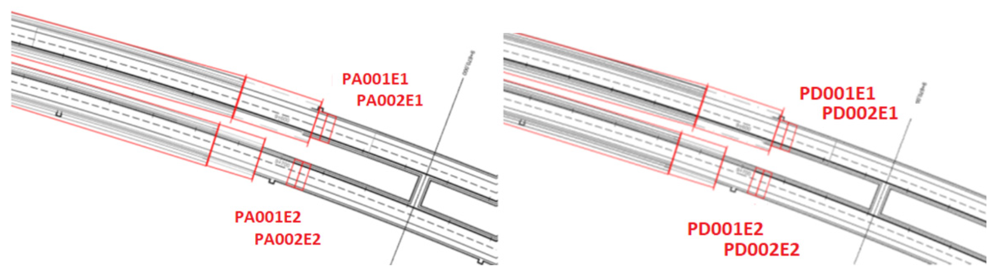
The documentation that is integrated in the collaborative environment scheme is linked to the model with the implementation of a stable algorithm, which uses a part of the character string of each file that is uploaded to the repository as a hashtag and as a code that links the file to the different parts of the model, as previously defined (
Figure 12). The document-coding system was agreed upon by the parties and integrated into the BEP.
5.6. Collaborative Working Scheme
The working scheme proposed for the definition of the collaborative workflow in the application of the BIM methodology in the Arnotegi tunnel is illustrated in
Figure 13.
For the overall management of the project, a role system was defined that allowed collaboration between the different agents involved in the project. In this way, it was possible to control the access of each user to their assigned areas with a simple system of authorisations.
5.7. Usage Data
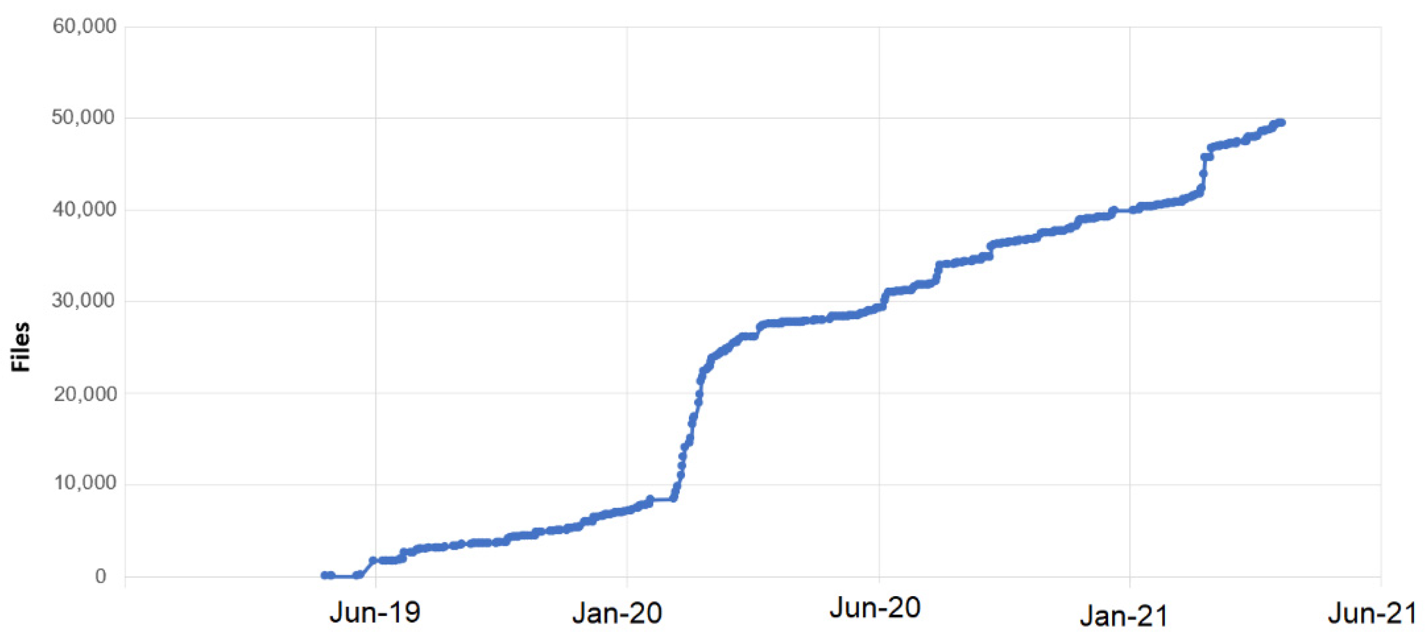
Throughout the development of the project, both the Vircore CDE and the BIM models developed have been tracked and monitored.
The evolution of this amount of information has been used as an indirect metric to assess the effectiveness of the proposed framework. In addition, on a monthly basis, it was verified that the main thematic reports whose drafting was contractually committed were correctly uploaded in the system and linked to the model.
At the end of the underground works, the volume of information stored in the common data environment reached 160 Gb and almost 50,000 files.
Figure 14 shows the evolution over time of the files uploaded to the common data environment. The sudden increase in the first months of 2020 is due to the start of the underground works.
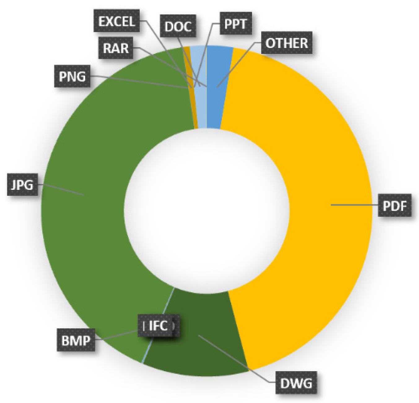
Figure 15 shows the type of files managed. Most of the files were pdf documents (43%) and jpg files (41%).
6. Conclusions
To make progress in the implementation of the BIM methodology in underground works projects and to use it for more than the traditional uses (3D visualisation and checking of interferences), it is necessary to establish a contractual framework that favours collaboration between all those involved in each project. In underground work projects, moreover, the execution models change every day, either because of the difference between the theoretical blast line and the real line, or because of the geotechnical uncertainty of the terrain; thus, the BIM management framework must be sensitive to this circumstance.
In the Arnotegi project, a BIM methodology with advanced uses has been implemented and set contractually, allowing a bidirectional integration between the model and the common data environment.
In addition, the framework of the BIM methodology in this project was able to determine a changing follow-up model according to the actual geometric and geotechnical information after each blasting phase.
These advanced uses of the BIM methodology have facilitated the transmission of graphic and non-graphic information to all the decision-making elements, enabling rapid and efficient management of all decisions regarding the progress of the underground work.
These results have the limitation of having been evaluated in a single implementation experience. Since underground works are usually very repetitive, they can be extended to all similar construction works, although it will be necessary to enlarge the sample and test them in other projects to definitively verify the advantages of the advanced uses of BIM that have been described in this paper.
Author Contributions
Conceptualization, J.-M.B.; methodology, J.-M.B., J.d.-P. and J.R.; formal analysis, J.-M.B. and J.d.-P.; writing—original draft preparation, J.-M.B.; writing—review and editing, J.-M.B.; supervision, J.R. All authors have read and agreed to the published version of the manuscript.
Funding
This research received no external funding.
Data Availability Statement
The data presented in this study are available on request from the corresponding author. The data are not publicly available due to confidentiality.
Acknowledgments
The authors want to acknowledge the promoter of the works, Interbiak, for its firm commitment to exploring the possibilities for the implementation of the BIM methodology in underground works.
Conflicts of Interest
The authors declare no conflict of interest.
References
- Diamond, R.S.; Kassel, B.G. A History of the Urban Underground Tunnel (4000 B.C.E.-1900 C.E.). J. Transp. Technol. 2018, 8, 11–43. [Google Scholar] [CrossRef] [Green Version]
- Huang, M.Q.; Ninić, J.; Zhang, Q.B. BIM, machine learning and computer vision techniques in underground construction: Current status and future perspectives. Tunn. Undergr. Space Technol. 2021, 108, 103677. [Google Scholar] [CrossRef]
- The Practice of Engineering in BIM Times. Available online: https://www.researchgate.net/publication/335028090_THE_PRACTICE_OF_ENGINEERING_IN_BIM_TIMES (accessed on 4 March 2022).
- Akintola, A.; Venkatachalam, S.; Root, D. Understanding BIM’s impact on professional work practices using activity theory. Constr. Manag. Econ. 2020, 38, 447–467. [Google Scholar] [CrossRef]
- Liz, J.T.; Gómez, J. Monográfico BIM. Rev. De Obras Públicas 2018, 3597, 3. [Google Scholar]
- Kupriyanovsky, V.; Voropaev, Y.; Pokusaev, O.; Klimov, A.; Dobrynin, A.; Gapanovich, D. BIM Technologies for Tunnels Used in Subways, Railways, Highways, and Hyperloop—IFC-Driven Real-Time Systems and Disruptive Innovation. Int. J. Open Inf. Technol. 2020, 8, 70–93. [Google Scholar]
- Li, S.; Zhang, Z.; Mei, G.; Lin, D.; Yu, J.; Qiu, R.; Su, X.; Lin, X.; Lou, C. Utilization of BIM in the construction of a submarine tunnel: A case study in Xiamen city, China. J. Civ. Eng. Manag. 2021, 27, 14–26. [Google Scholar] [CrossRef]
- Geng, D.; Vojtasik, K. Application of BIM technology in subway station construction. Int. Res. J. Eng. Technol. (IRJET) 2018, 10, 195–198. [Google Scholar]
- Chmelina, K.; Eichhorn, A. Applications of knowledge-based systems in technical surveying. J. Appl. Geod. 2008, 2, 31–38. [Google Scholar] [CrossRef]
- Beer, G. (Ed.) Technology Innovation in Underground Construction; Taylor & Francis Group: London, UK, 2010. [Google Scholar]
- Marinos, V.; Prountzopoulos, G.; Fortsakis, P.; Koumoutsakos, D.; Korkaris, K.; Papouli, D. Tunnel Information and Analysis System: A Geotechnical Database for Tunnels. Geotech. Geol. Eng. 2013, 31, 891–910. [Google Scholar] [CrossRef]
- Wu, J.; Chen, J.; Chen, G.; Wu, Z.; Zhong, Y.; Chen, B.; Ke, W.; Huang, J. Development of Data Integration and Sharing for Geotechnical Engineering Information Modeling Based on IFC. Adv. Civ. Eng. 2021, 2021. [Google Scholar] [CrossRef]
- Sharafat, A.; Khan, M.; Latif, K.; Seo, J. BIM-Based Tunnel Information Modeling Framework for Visualization, Management, and Simulation of Drill-and-Blast Tunneling Projects. J. Comput. Civ. Eng. 2020, 35, 04020068. [Google Scholar] [CrossRef]
- Athanasopoulo, A.; Bezuijen, A.; Bogusz, W.; Bournas, D.; Brandtner, M.; Breunese, A.; Burbaum, U.; Dimova, S.; Frank, R.; Ganz, H.; et al. Standardisation needs for the design of underground structures EU JRC 2019. In JRC Technical Reports; European Commission: Brussels, Belgium, 2019. [Google Scholar] [CrossRef]
- Geospatial Commission. The UK’s Geospatial Strategy. 2020. Available online: https://www.gov.uk/government/publications/unlocking-the-power-of-locationthe-uks-geospatial-strategy (accessed on 4 March 2022).
- Gil, M.; Rivas, P.; Rojo, L.A.; Temiño, Y. Variante Sur Metropolitana de Bilbao. In Fase I. Revista de Obras Públicas; Colegio de Ingenieros de Caminos: Madrid, Spain, 2014; p. 3554. [Google Scholar]
- Lin, Y.; Lo, N.; Hu, H.; Hsu, Y. Collaboration-Based BIM Model Development Management System for General Contractors in Infrastructure Projects. J. Adv. Transp. 2020, 2020, 8834389. [Google Scholar] [CrossRef]
- Vircore (Version 2021) 2021. Available online: https://vircore.es/ (accessed on 4 March 2022).
| Publisher’s Note: MDPI stays neutral with regard to jurisdictional claims in published maps and institutional affiliations. |
© 2022 by the authors. Licensee MDPI, Basel, Switzerland. This article is an open access article distributed under the terms and conditions of the Creative Commons Attribution (CC BY) license (https://creativecommons.org/licenses/by/4.0/).


