
Ontology-Based Approach Supporting Multi-Objective Holistic Decision Making for Energy Pile System


Abstract
:1. Introduction
2. Multi-Objective Holistic Design and Development of OntoEPS
2.1. Determination of the Key Parameters for Holistic Design of EPS
- (1)
- The equipment cost
- (2)
- The cost recovery period
- (3)
- The CO2 emission reduction
- (4)
- The vertical bearing capability (VBC)
2.2. Design and Development of OntoEPS
2.2.1. The System Framework of OntoEPS
2.2.2. The Development of OntoEPS System
2.2.3. The Procedure of Ontology Development
| Equation: | |
| SWRL: | Energy_pile_system(?Es)^Heat_transfer_tube_cost(?Es,?TubeCost)^Ground_pump_cost(?Es,?PumpCost)^swrlb:add(?EquipmentCost,?TubeCost,?PumpCost)->Equipment_cost(?Es,?EquipmentCost) |
| SQWR | Energy_pile_system(?Es)^Heat_transfer_tube_cost(?Es,?tube_cost)^Ground_pump_cost(?Es,?pump_cost)^Equipment_cost(?Es,?equipment_cost)->sqwrl:select(?Es, ?tube_cost, ?pump_cost,?equipment_cost) |
2.3. Ontology Verification
- (1)
- Semantic verification
- (2)
- Syntactical verification
- (3)
- Rules verification
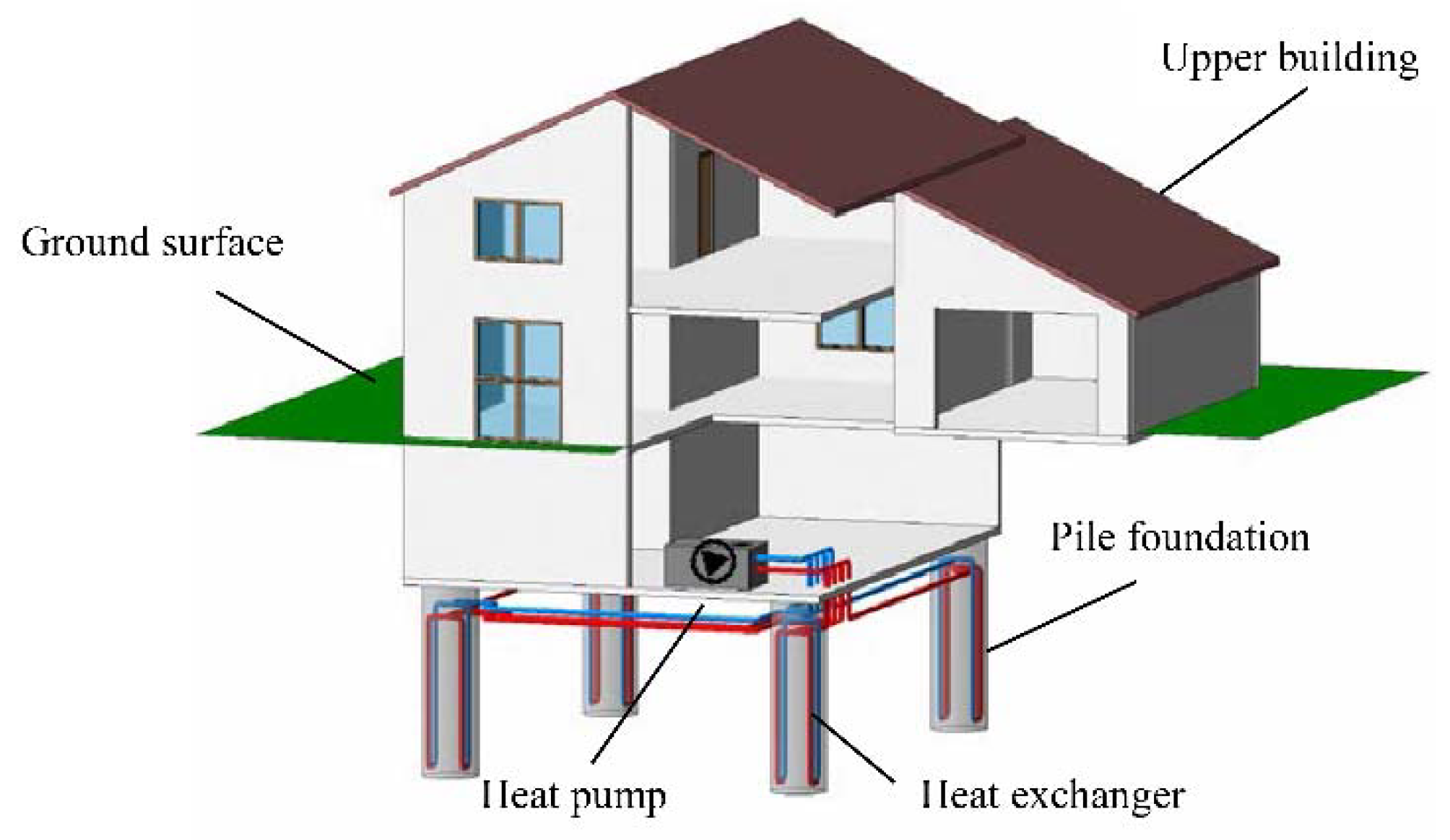
3. Case study
3.1. Case Study Description
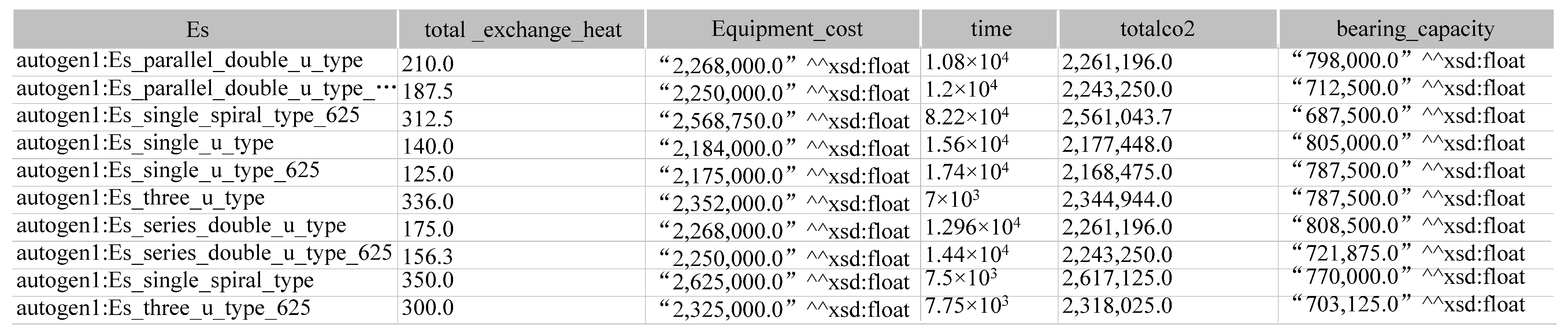
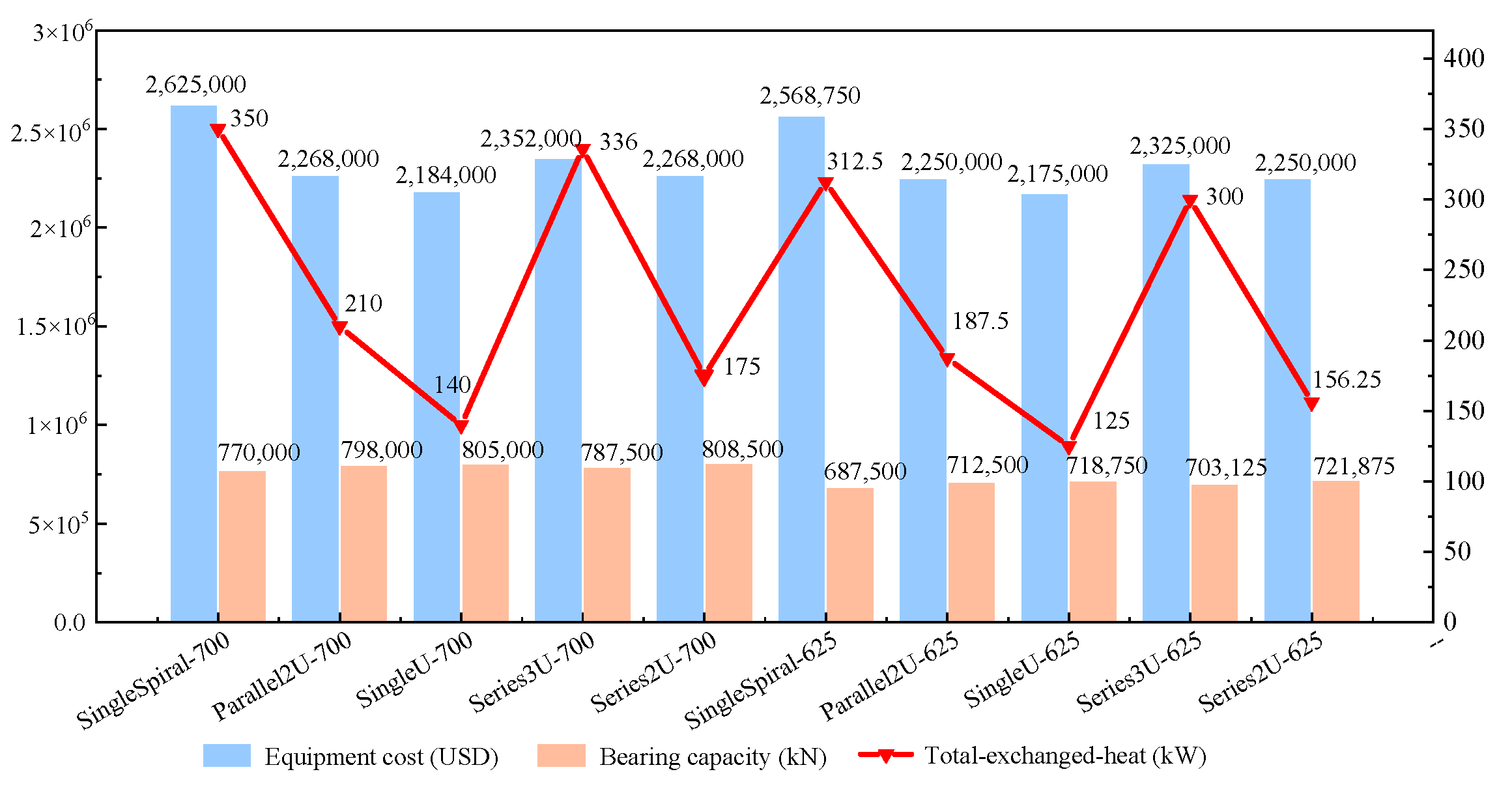
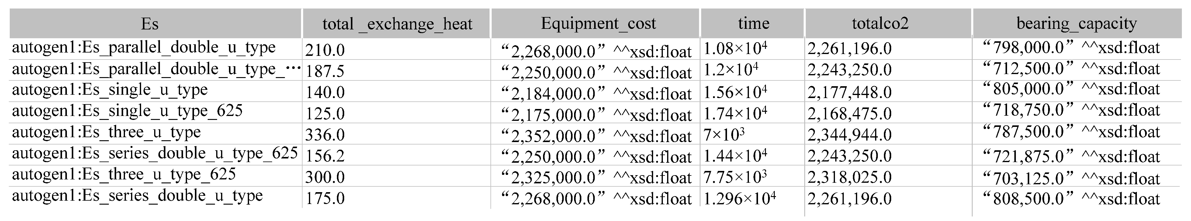
3.2. Applications
3.3. Discussion
- (1)
- For the cost, we only consider the cost of the material. The cost of labor and equipment is neglected.
- (2)
- The developed OntoEPS is not fully automated. Users still need to compile and type the corresponding SQWRL rules to achieve a specific function.
- (3)
- The developed OntoEPS is limited in the Protégé software environment. That means the engineers should have basic knowledge of ontology to use this approach in practice.
4. Conclusions
Author Contributions
Funding
Institutional Review Board Statement
Informed Consent Statement
Data Availability Statement
Conflicts of Interest
References
- Huovila, P. Buildings and Climate Change: Status, Challenges, and Opportunities, 1st ed.; United Nations Environment Programme: Nairobi, Kenya, 2007; pp. 17–24. [Google Scholar]
- Reza, F.; Brynhildur, D. Climate impact on energy demand for space heating in Iceland. Clim. Chang. Econ. 2016, 7, 16500044. [Google Scholar]
- Isaac, M.; Van Vuuren, D.P. Modeling global residential sector energy demand for heating and air conditioning in the context of climate change. Energy Policy 2009, 37, 507–521. [Google Scholar] [CrossRef]
- Morino, K.; Oka, T. Study on heat exchanged in soil by circulating water in a steel pile. Energy Build. 1994, 21, 65–78. [Google Scholar] [CrossRef]
- Omer, A.M. Ground-source heat pumps systems and applications. Renew. Sustain. Energy Rev. 2008, 12, 344–371. [Google Scholar] [CrossRef]
- Omer, J.; Haroglu, H. Tests on model piled rafts in sand: Measured settlements compared with finite element predictions. Geotech. Geol. Eng. 2021, 39, 3271–3283. [Google Scholar] [CrossRef]
- Man, Y.; Yang, H.; Diao, N.; Liu, J.H.; Fang, Z.H. A new model and analytical solutions for borehole and pile ground heat exchangers. Int. J. Heat Mass Tran. 2010, 53, 2593–2601. [Google Scholar] [CrossRef]
- Hu, P.F.; Zha, J.; Lei, F.; Zhu, N.; Wu, T.H. A composite cylindrical model and its application in analysis of thermal response and performance for energy pile. Energy Build. 2014, 84, 324–332. [Google Scholar] [CrossRef]
- Zhang, W.K.; Cui, P.; Liu, J.H.; Liu, X.T. Study on heat transfer experiments and mathematical models of the energy pile of building. Energy Build. 2017, 152, 643–652. [Google Scholar] [CrossRef]
- Ghasemi, F.O.; Basu, P. A practical heat transfer model for geothermal piles. Energy Build. 2013, 66, 470–479. [Google Scholar] [CrossRef]
- Gashti, E.H.N.; Uotinen, V.M.; Kujala, K. Numerical modelling of thermal regimes in steel energy pile foundations: A case study. Energy Build. 2014, 69, 165–174. [Google Scholar] [CrossRef]
- Fadejev, J.; Kurnitski, J. Geothermal energy piles and boreholes design with heat pump in a whole building simulation software. Energy Build. 2015, 106, 23–34. [Google Scholar] [CrossRef]
- Hemmingway, P.; Long, M. Energy piles: Site investigation and analysis. Geotech. Eng. 2013, 166, 561–575. [Google Scholar] [CrossRef]
- Miyara, A.; Tsubaki, K.; Inoue, S.; Yoshida, K. Experimental study of several types of ground heat exchanger using a steel pile foundation. Renew. Energy 2011, 36, 764–771. [Google Scholar]
- You, S.; Cheng, X.H.; Guo, H.X.; Yao, Z.Q. In-situ experimental study of heat exchange capacity of CFG pile geothermal exchangers. Energy Build. 2014, 79, 23–31. [Google Scholar] [CrossRef]
- Kong, G.Q.; Wu, D.; Liu, H.L.; Laloui, L.; Cheng, X.H.; Zhu, X. Performance of a geothermal energy deicing system for bridge deck using a pile heat exchanger. Int. J. Energy Res. 2019, 43, 596–603. [Google Scholar] [CrossRef] [Green Version]
- Laloui, L. In-situ testing of a heat exchanger pile. In Proceedings of the Geo-Frontiers 2011, Dallas, TX, USA, 13–16 March 2011; pp. 410–419. [Google Scholar]
- Binod, A.; Kenichi, S.; Peter, B.; Amis, T. Thermo-mechanical behaviour of energy piles. Geotechnique 2012, 62, 503–519. [Google Scholar]
- Ozudogru, T.Y.; Olgun, C.G.; Arson, C.F. Analysis of friction induced thermo-mechanical stresses on a heat exchanger pile in isothermal soil. Geotech. Geol. Eng. 2015, 33, 357–371. [Google Scholar] [CrossRef]
- Loveridge, F.A.; Powrie, W. Pile heat exchangers: Thermal behaviour and interactions. Proc. ICE-Geotech. Eng. 2013, 166, 178–196. [Google Scholar] [CrossRef] [Green Version]
- Jeong, S.; Lim, H.; Lee, J.K.; Kim, J.W. Thermally induced mechanical response of energy piles in axially loaded pile groups. Appl. Therm. Eng. 2014, 71, 608–615. [Google Scholar] [CrossRef]
- Chen, D.; McCartney, J.S. Parameters for load transfer analysis of energy piles in uniform nonplastic soils. Int. J. Geomech. 2016, 17, 04016159. [Google Scholar] [CrossRef] [Green Version]
- Morrone, B.; Coppola, G.; Raucci, V. Energy and economic savings using geothermal heat pumps in different climates. Energy Convers. Manag. 2014, 88, 189–198. [Google Scholar] [CrossRef]
- Ghoreishi-Madiseh, S.A.; Kuyuk, A.F. A techno-economic model for application of geothermal heat pump systems. Energy Procedia 2017, 142, 2611–2616. [Google Scholar] [CrossRef]
- Ahmed, V.; Pathmeswaran, R.; Aouad, G. A generic framework for the development of standardised learning objects within the discipline of construction management. J. Educ. Built Environ. 2007, 2, 115–135. [Google Scholar] [CrossRef] [Green Version]
- Zhang, K.; Liao, P.C. Ontology of ground source heat pump. Renew. Sustain. Energy Rev. 2015, 49, 51–59. [Google Scholar] [CrossRef]
- Yurchyshyna, A.; Zarli, A. An ontology-based approach for formalisation and semantic organisation of conformance requirements in construction. Autom. Constr. 2009, 18, 1084–1098. [Google Scholar] [CrossRef]
- Dibley, M.; Li, H.; Rezgui, Y.; Miles, J. An ontology framework for intelligent sensor-based building monitoring. Autom. Constr. 2012, 28, 1–14. [Google Scholar] [CrossRef]
- Hou, S.; Li, H.; Rezgui, Y. Ontology-based approach for structural design considering low embodied energy and carbon. Energy Build. 2015, 102, 75–90. [Google Scholar] [CrossRef]
- Gu, J.; Qi, F.; Wu, J. Forecasting on China’s civil automobile owned based on Gompertz model. Technol. Econ. 2010, 29, 57–62. [Google Scholar]
- Noy, N.F.; McGuinness, D.L. Ontology development 101: A guide to creating your first ontology. Comput. Sci. 2001. Available online: https://www.csee.umbc.edu/courses/graduate/691/fall17/01/papers/ontology101.pdf (accessed on 11 December 2021).
- Roussey, C.; Pinet, F.; Kang, M.A.; Corcho, O. An introduction to ontologies and ontology engineering. In Ontologies in Urban Development Projects; Springer: London, UK, 2011; pp. 9–38. [Google Scholar]
- Horrocks, I.; Patel-Schneider, P.F.; Boley, H. SWRL: A semantic web rule language combining OWL and RuleML. W3C Memb. Submiss. 2004, 21, 1–31. [Google Scholar]
- Völker, J.; Vrandečić, D.; Sure, Y. AEON–An approach to the automatic evaluation of ontologies. Appl. Ontol. 2008, 3, 41–62. [Google Scholar] [CrossRef]
- Noy, N.F. Interactive Tools for Ontology Merging and Mapping. Int. J. Hum. Comput. Stud. 2003, 59, 983–1024. [Google Scholar] [CrossRef]
- Hovy, E. Comparing Sets of Semantic Relations in Ontologies; Springer: Dordrecht, The Netherlands, 2002; pp. 91–110. [Google Scholar]


| The area of heat load | 400,000 m2 |
| Peak of hourly dynamic load | 200 kW |
| The type of the pile | bored pile |
| The number of the pile | 700 |
| The length of the pile | 10 m |
| The type of the heat pump | FSLC 2330H Centrifugal magnetic suspension heat pump |
| The number of the heat pump | 2 |
| The price of the heat pump | 0.175 million (USD) per unit |
| The type of the heat exchanger tube | PE plastic tube |
| The price of the heat exchanger tube | 1 USD/meter |
| The price of the electricity | 0.17 USD/kWh |
| Heat Exchanger Type | Length (m) | Heat Exchanged Per Meter (W/m) | Vertical Ultimate Bearing Capacity (kN) |
|---|---|---|---|
| Series double U type | 40 | 25 | 2310 |
| Parallel double U type | 40 | 30 | 2280 |
| Single U type | 20 | 20 | 2300 |
| Single spiral type | 125 | 50 | 2200 |
| Three U type | 60 | 48 | 2250 |
| Rule Number | Rule Type | Specification |
|---|---|---|
| R.1 | Equipment Cost (SWRL) | Calculating heat exchanger costs: Energy_pile_system(?Es)^hasPile_type(?Es,?Pile)^pile_type(?Pile)^numbers(?Pile,?N)^hasHeat_transfer_tube_type(?Pile,?Tube)^Heat_transfer_tube_type(?Tube)^Length(?Tube,?L)^Cost(?Tube,?C)^swrlb:multiply(?TubeCost,?L,?C,?N)->Heat_transfer_tube_cost(?Es, ?TubeCost) |
| R.2 | Calculating pump costs: Energy_pile_system(?Es)^hasGround_pump_type(?Es,?P)^Ground_pump_type(?G)^Cost(?G,?C)^numbers(?G,?N)^swrlb:multiply(?PumpCost,?C,?N)->Ground_pump_cost(?Es, ?PumpCost) | |
| R.3 | Calculating equipment cost: Energy_pile_system(?Es)^Heat_transfer_tube_cost(?Es,?TubeCost)^Ground_pump_cost(?Es,?PumpCost)^swrlb:add(?EquipmentCost,?TubeCost,?PumpCost)->Equipment_cost(?Es, ?EquipmentCost) | |
| R.4 | CostRecovery Period (SWRL) | Calculating the work of heat exchanged by the system per hour: Energy_pile_system(?Es)^hasPile_type(?Es,?pile)^pile_type(?pile)^Heat_exchange_per_meter(?pile,?heat)^Length(?pile,?L)^numbers(?pile,?N)^swrlb:multiply(?total_exchange_heat,?heat,?L,?N,0.001) -> Total_exchange_heat(?Es, ?total_exchange_heat) |
| R.5 | Calculating the cost recovery period: Energy_pile_system(?Es)^Equipment_cost(?Es, ?equipment_cost)^Electricity_price(?Es, ?electricity_price)^Total_exchange_heat(?Es,?total_exchange_heat)^swrlb:multiply(?x,?electricity_price, ?total_exchange_heat) ^ swrlb:divide(?y, ?equipment_cost, ?x) -> Cost_recovery_time(?Es, ?y) | |
| R.6 | CO2 emissionsreduction during cost recovery period (SWRL) | Calculating CO2 emissions reduction during cost recovery period: Energy_pile_system(?Es)^Co2(?Es,?co2)^Total_exchange_heat(?Es,?heat)^Cost_recovery_time(?Es,?time) ^swrlb:multiply(?total_co2, ?co2, ?heat, ?time) -> TotalCo2(?Es, ?total_co2) |
| R.7 | Vertical bearing capacity of EPS (SWRL) | Calculating vertical bearing capacity of energy pile system: Energy_pile_system(?Es)^hasPile_type(?Es,?pile)^pile_type(?pile)^Qvk(?pile,?qvk)^K(?pile,?k)^numbers(?pile,?N)^swrlb:divide(?ra,?qvk,?k)^swrlb:multiply(?total_bearing,?ra,?N)->Total_vertical_bearing_capacity(?Es, ?total_bearing) |
| R.8 | Querying rules (SQWRL) | Energy_pile_system(?Es)^Equipment_cost(?Es,?equipment_cost)^Total_exchange_heat(?Es, ?total_exchange_heat)^Cost_recovery_time(?Es,?time)^TotalCo2(?Es,?totalco2)^Total_vertical_bearing_capacity(?Es,?bearing_capacity)->sqwrl:select(?Es, ?equipment_cost,?time, ?totalco2,?bearing_capacity) |
| Rule Number | Related Indicators | SQWRL Rule |
|---|---|---|
| R.1 | Design solutions with equipment cost less than 0.4 million (USD) | Energy_pile_system(?Es)^Equipment_cost(?Es,?equipment_cost)^Total_exchange_heat(?Es, ?total_exchange_heat)^Cost_recovery_time(?Es,?time)^TotalCo2(?Es,?totalco2)^Total_vertical_bearing_capacity(?Es,?bearing_capacity)^swrlb:lessThan(?equipment_cost,2500000)-> sqwrl:select(?Es, ?total_exchange_heat, ?equipment_cost, ?time, ?totalco2, ?bearing_capacity) |
| R.2 | Design solutions with the bearing capacity greater than 7 × 10⁶ kN | Energy_pile_system(?Es)^Equipment_cost(?Es,?equipment_cost)^Total_exchange_heat(?Es, ?total_exchange_heat)^Cost_recovery_time(?Es,?time)^TotalCo2(?Es,?totalco2)^Total_vertical_bearing_capacity(?Es,?bearing_capacity)^swrlb:greaterThan(?bearing_capacity,700000)-> sqwrl:select(?Es, ?total_exchange_heat, ?equipment_cost, ?time, ?totalco2, ?bearing_capacity) |
| R.3 | Design solutions with total exchanged heat greater than 200 kW and equipment cost less than 0.4 million (USD) | Energy_pile_system(?Es)^Equipment_cost(?Es,?equipment_cost)^Total_exchange_heat(?Es, ?total_exchange_heat)^Cost_recovery_time(?Es,?time)^TotalCo2(?Es,?totalco2)^Total_vertical_bearing_capacity(?Es,?bearing_capacity)^swrlb:greaterThan(?total_exchange_heat,200)^ swrlb:lessThan(?equipment_cost,2500000)->sqwrl:select(?Es, ?total_exchange_heat, ?equipment_cost, ?time, ?totalco2, ?bearing_capacity) |
Publisher’s Note: MDPI stays neutral with regard to jurisdictional claims in published maps and institutional affiliations. |
© 2022 by the authors. Licensee MDPI, Basel, Switzerland. This article is an open access article distributed under the terms and conditions of the Creative Commons Attribution (CC BY) license (https://creativecommons.org/licenses/by/4.0/).
Share and Cite
Meng, K.; Cui, C.; Li, H.; Liu, H. Ontology-Based Approach Supporting Multi-Objective Holistic Decision Making for Energy Pile System. Buildings 2022, 12, 236. https://doi.org/10.3390/buildings12020236
Meng K, Cui C, Li H, Liu H. Ontology-Based Approach Supporting Multi-Objective Holistic Decision Making for Energy Pile System. Buildings. 2022; 12(2):236. https://doi.org/10.3390/buildings12020236
Chicago/Turabian StyleMeng, Kun, Chunyi Cui, Haijiang Li, and Hailong Liu. 2022. "Ontology-Based Approach Supporting Multi-Objective Holistic Decision Making for Energy Pile System" Buildings 12, no. 2: 236. https://doi.org/10.3390/buildings12020236