Article

Critical Experiments for Structural Members of Micro Image Strain Sensing Sensor Based on Smartphone and Microscope

1
School of Civil Engineering, Dalian University of Technology, Dalian 116024, China
2
State Key Laboratory of Coastal and Offshore Engineering, Dalian University of Technology, Dalian 116024, China
3
College of Civil Engineering and Architecture, Wenzhou University, Wenzhou 325035, China
4
Northeast Branch China Construction Eighth Engineering Division Co., Ltd., Dalian 116019, China
*
Author to whom correspondence should be addressed.
Buildings 2022, 12(2), 212; https://doi.org/10.3390/buildings12020212
Submission received: 6 January 2022 / Revised: 10 February 2022 / Accepted: 11 February 2022 / Published: 14 February 2022
(This article belongs to the Section Construction Management, and Computers & Digitization)

Abstract

:
Strain is one of the key concerns of structural health monitoring (SHM), and effective measurement of structural strain is very important for structural health condition assessment. The purpose of this paper is to investigate the application of the micro image strain sensing (MISS) sensor based on smartphone and microscope for measuring strain parameters of structural members. Firstly, metal tensile tests were performed to verify the effectiveness of the MISS sensor, and the strain results measured by the fiber Bragg grating (FBG) sensor and the MISS sensor were compared. The results showed that the mean error between the MISS and FBG sensor measured results is 7.1 με in the metal tensile test. Then, a concrete beam bending test was carried out; the mean relative error of strain values between the FBG sensor and the MISS sensor is 2.5%. Overall, the strain measurements of the MISS sensor matched well with those from the FBG sensor in each experiment. This study validates the reliability and accuracy of the MISS sensor for strain detection and the MISS sensors can play a more powerful role in SHM due to their robustness, simplicity, and low cost.

1. Introduction

The structural strain plays a significant role in the structural health monitoring (SHM) system, as it could intuitively reflect the local characteristics of the structure and easily perform the structural safety assessment [1,2,3,4]. Currently, the strain sensors for SHM commonly include electrical resistance strain gages (ESGs) [5,6,7], fiber optic strain sensors (FOSs) [8,9,10,11], vibrating wire strain gages (VWSGs) [12,13], and digital imaging correlation (DIC) [14,15,16,17]. Among these sensors, ESGs are usually required to form a measurement circuit with wires, which would cause complicated situations when there are many measurement points and is subject to electromagnetic signal interference. FOSs are costly to install in large structures and the fibers are prone to breakage. Simultaneously, the potential damage to structural integrity may occur when FOSs are embedded in the concrete or other materials. The great advantage of VWSGs is that they are stable and simple, but their slow response speed is unsuitable for dynamic monitoring, and the steel-string is prone to creeping and relaxation. DIC technology is a non-contact, non-destructive, full-field measurement method, which has received significant attention in recent years. However, the accuracy of DIC technology is influenced by image noise, image processing algorithms, and measurement equipment. Additionally, DIC technology can only measure the area within the camera’s field of view. It is worth noting that a larger field of view reduces the resolution of the camera, which affects the resolution and accuracy of the measurements. In other words, DIC technology cannot achieve a larger field of view and higher resolution at the same time [18]. The high price of DIC equipment also limited its widespread use in civil engineering structures. Furthermore, the above-mentioned traditional sensors often require special equipment and professional technicians to operate, which restricts the range of application in practical engineering. Therefore, it is necessary to develop an economical and practical strain sensor that can still provide reliable results.
Various novel strain sensors for SHM have been extensively studied [19]. For example, Tondolo et al. [20] designed a smart steel system to measure the strain of reinforced concrete members by implanting a commercial barometric pressure MEMS sensor into an appropriate sealed cavity in the reinforcement. Gregori et al. [21] invented a wireless strain gauge that combines an RFID tag with a common thin-film resistive strain gauge, overcoming the installation and maintenance problems of wireless sensor networks. Morgese et al. [22] developed a two-stage monitoring method combining distributed optical fiber sensors and digital image correlation techniques.
Notably, the development of smartphones offers new opportunities for low-cost sensors. One of the major advantages of using smartphones for SHM is that they can create a cyber-physical system using embedded operating systems and wireless communication hardware. Moreover, smartphones can be used as a crowdsourcing SHM platform that is fueled by citizens [23,24]. For example, some researchers employ smartphones to measure acceleration [25,26,27], displacement [28,29,30,31], cracking [32,33,34], construction safety [35,36,37], and other parameters of buildings. With smartphones equipped with improved cameras, some researchers (e.g., Yu et al. [38]) have been focused on using smartphones combined with image processing algorithms to implement visual monitoring of structural strain. However, the measurement area of the specimens studied by Yu et al. is only 20 mm × 25 mm, and the measurement error obtained is 56 με. Therefore, the method of measuring structural strain based on smartphones is not sufficiently mature and still needs further research.
To measure structural strain more conveniently and in a low-cost manner, the principle of micro image strain sensing (MISS) sensor was proposed by our team [39]. In the previous study, the deformation process of the structure was simulated by the movement of the stepper motor, and then it was found that the MISS sensor showed good accuracy and stability. However, there are still some problems to be solved if the MISS sensor is applied to the real structures. The first issue is the connection between the smartphone and the sensor. The smartphone camera needs to maintain a constant field of view during the image capture process, which requires a reliable connection between the smartphone and the sensor. The suitability of different smartphone models also needs to be taken into account. Another task is to carry out tests on the actual deformed elements. In previous studies, the deformation of the structure was simulated by the movement of a stepper motor, but the two processes are not identical. Further tests are required to verify whether the actual structural component strain results can be obtained accurately and effectively. The main purpose of this study is to solve the above two problems.
This paper researches the application of the MISS sensor based on smartphone and microscope in actual deformed structural members. We begin by introducing a fixed device that connects a smartphone with a MISS sensor and its operation. Then, the metal tensile tests under different loading conditions were carried out to verify the sensor performance. In addition, the MISS sensor was used for a bending experiment on reinforced concrete (RC) beam. The results show that the MISS sensor can effectively measure the development of the surface strain of deformed structures. In the end, the next stages of the research are discussed.

2. Measurement Method and Principle

2.1. Method for Fabricating the Sensor
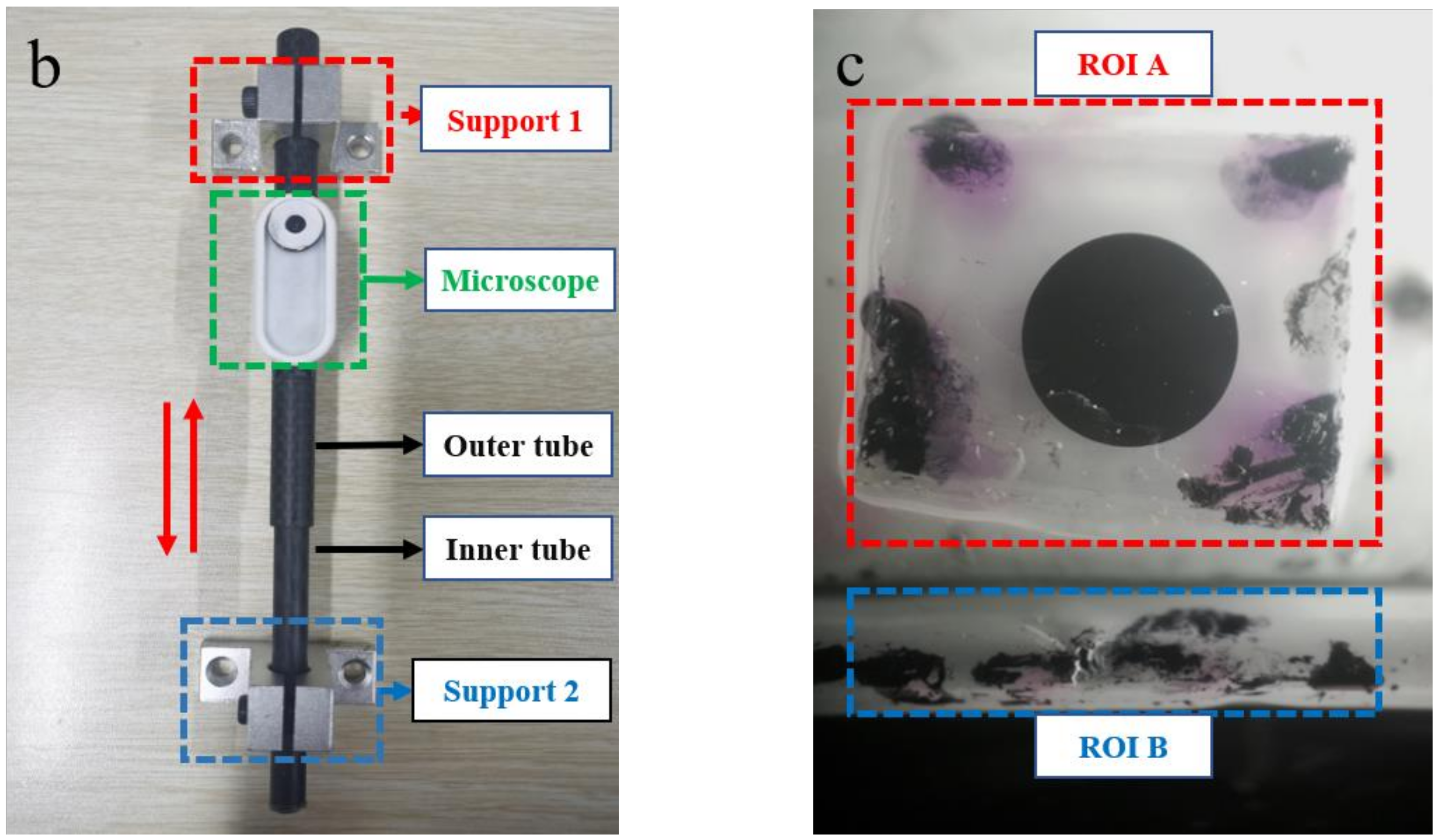
A novel strain sensor for civil structural health monitoring has been proposed recently in the laboratory of the authors [39]. As shown in Figure 1a,b, the main body of the sensor consists of two carbon fiber tubes of different diameters, and the two tubes are referred to as inner and outer tubes respectively. During the operation of the sensor, the outer tube is fixed to the support 1, the inner tube is fixed to the support 2, and the inner and outer tubes move freely along the axial direction of the tubes in a piston connection. The outer tube of the sensor is mounted with a microscope that is paired with a smartphone camera to take photos. Underneath the microscope is a semi-cylindrical support platform, which is fixed to the outer tube of the sensor.
Figure 1c illustrates the field of view obtained by the smartphone camera. The image is split into two parts: the upper part is the region of interest (ROI) A, which is located on the support platform connected to the outer tube; the lower part is the ROI B, which is located on the carbon fiber rod connected to the inner tube. Some irregular shapes are preset on the support platform of the MISS sensor as feature points. The ROI A of the image is actually a collection of feature points containing the movement information of support 1, and similarly, the ROI B is actually a collection of feature points containing the movement information of support 2. Moreover, the black circle in the ROI A is also used for the pixel equivalent. When the structure is deformed, two supports are anchored to the surface of the structure, and the supports drive the inner and outer tubes to move relative to each other. At the same time, the support platform moves rigidly with the outer tube and the carbon fiber rod moves rigidly with the inner tube. As a result, the relative positions of the ROI A on the support platform and the ROI B on the carbon fiber rod change. Additionally, the mean strain on the surface of the measured structure is obtained by dividing the relative displacement of the ROI A and ROI B by the distance between the two supports.
In this paper, the speeded-up robust feature (SURF) algorithm [40] is used to identify the movement of the feature points within the ROI, and the M-estimator Sample Consensus (MSAC) algorithm [41] is used to eliminate the outliers of the feature points. The SURF algorithm is mainly divided into three steps: feature point detection, feature point description, and feature point matching, as shown in Figure 2. The feature point detector uses a fast Hessian matrix to detect feature points, such as corner points and T-intersection points. To describe the directional characteristics of the feature points, the integral image is used to generate the feature description operator, which performs Haar wavelet response operation on the image. Finally, the similarity measure of two feature point operators is described by Euclidean distance. However, in the feature point matching stage, a small deviation angle in the main direction can also cause errors in feature matching, so the MSAC algorithm is used to eliminate matching outliers. Figure 2 presents the calculation process of feature points.

2.2. Fixing Device

The MISS sensor requires a stable and constant view during the measurement process, so the camera of the smartphone needs to be relatively static with the microscope which provides the magnification function. In other words, it means that the smartphone needs to be consistent with the movement of the outer tube and the support 1. Since it is considered that fixing the phone to the outer tube might cause the outer tube to be deflected due to the smartphone’s self-weight, we finally decide to fix the smartphone to the support 1 of the sensor.
As we use various smartphones as measurement devices, a small phone holder was designed in this experiment. In the mobile phone market, if the model of phone A is different from phone B, then the locations of the cameras are usually different as well. Consequently, minor adjustments to the fixation of the smartphone to the sensor are required when the measuring device is a different smartphone. The holder can adjust the length and angle of the x-axis, y-axis, and z-axis by rotating the connecting part, so that the phone camera has the best view. So, this phone fixing device can easily adjust the placement of the phone; the specific design is shown in Figure 3.

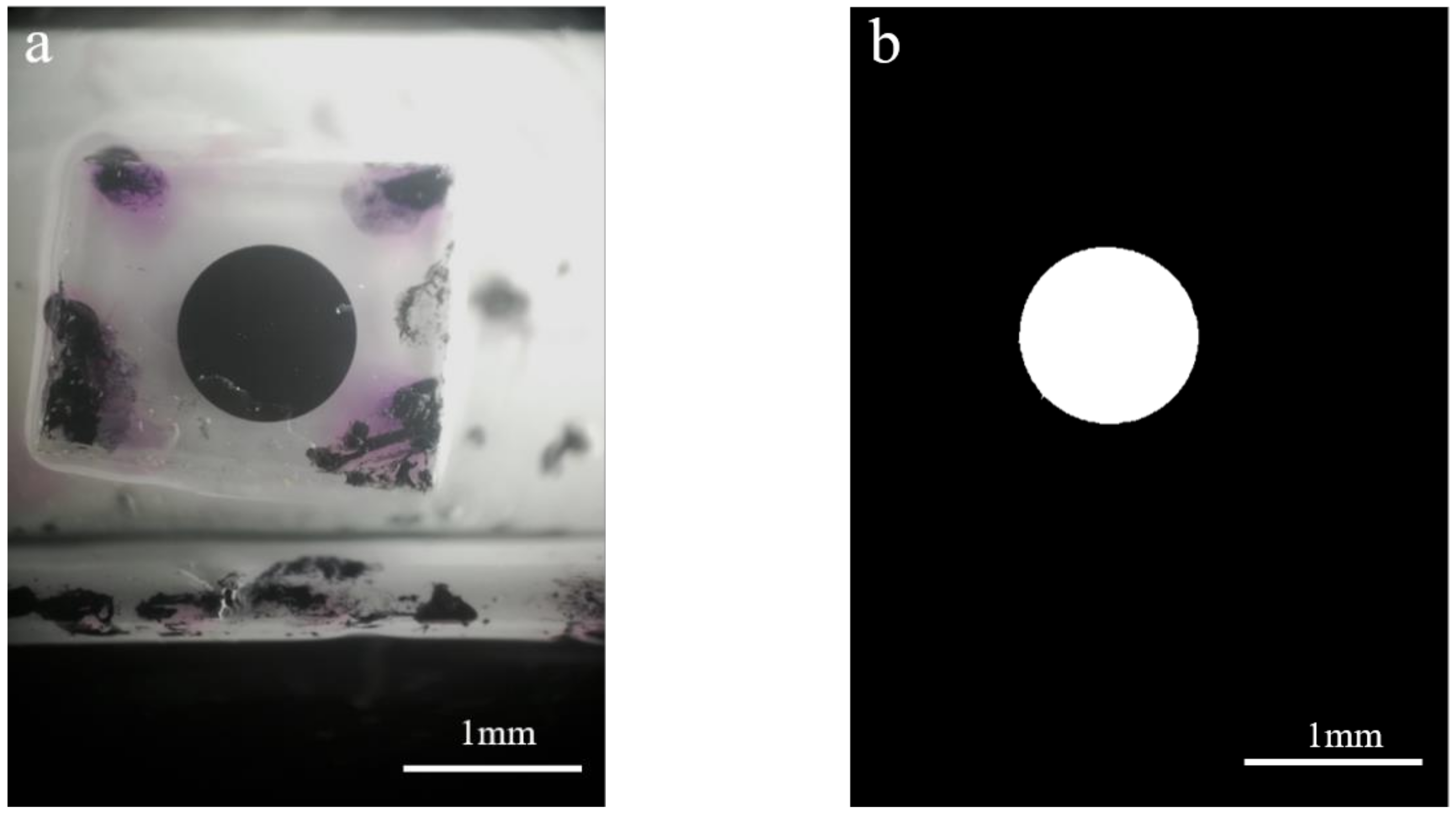
2.3. Sensing Principle

When the structural surface is deformed, the position of the support 1 and support 2 of the sensor is changed, which drives the position of ROI A and ROI B to change as well. Define the coordinates of the initial reference image before deformation as a (xa, ya) for ROI A and b (xb, yb) for ROI B. Similarly, the coordinates of the feature points of the deformed image are a′ (xa′, ya′) and b′ (xb′, yb′) respectively. Specifically, xa, ya are the abscissa pixel values and ordinate pixel values of the feature point a in ROI A before deformation, and xb, yb represent ROI B. The coordinate origin is the upper left corner of the image, and the coordinates are in pixels. As mentioned above, the smartphone is fixed to the support 1 (see Figure 3), so that the camera remains relatively stationary with the ROI A fixed to the outer tube. This also means that the coordinates of the feature points located in the ROI A remain unchanged during the deformation process, but the values of a (xa, ya) and a′ (xa′, ya′) may be unequal due to focus drift. The structural strain is not accurate if only the feature points in ROI B are selected for calculation; it becomes necessary to modify the result.
The distance between markers before and after the deformation is expressed as Euclidean distance. Figure 4 presents the coordinate map of relative displacement.
The modified formula is:
Δ l = x b x b x a x a 2 + y b y b y a y a 2
where Δl is the coordinate change value of the same feature point before and after deformation. As Δl is calculated using the pixel coordinate system, the unit of Δl is pixels. xa, ya are the abscissa values and ordinate values of the feature point in ROI A before deformation, xb, yb represent the ROI B. Similarly, xa′, ya′ are the abscissa values and ordinate values of the feature point in ROI A after deformation, and xb′, yb′ in ROI B are represented in the same format.
The single complete image acquired by the MISS sensor is exhibited in Figure 5a. Firstly, the image is grayed and opened to eliminate the influence of the interference point in the marked circle area. Then the grayscale image is binarized to obtain an image containing only the marked circle, as shown in Figure 5b.
The number of pixels contained in the circle area is calculated as N, and thus the number of pixels in the radius of the calibrated circle can be found as n:
n = N π
The actual size of the calibration circle radius is 0.5 mm, so the pixel equivalent k (mm/pixel) in the image can be obtained by the following equation:
k = 2 n
L (mm) is the distance between support 1 and support 2, then the mean strain:
ε = Δ l × k L
The effect of temperature on the MISS sensors has been studied in [39] and an empirical formula for the effect of temperature on the MISS sensor has been obtained:
D T = 0.015 T 2 + 2.051 T
where DT is the micro-strain value of the MISS sensor affected by temperature in με, and T represents the temperature of the environment where the MISS sensor is located in °C. The influence of temperature on the sensor is eliminated by the empirical formula.

3. Experimental Details

3.1. Metallic Materials Tensile Test

To study the effectiveness of the MISS sensor in measuring the strain on the surface of the structure, the metal specimens were selected as a simple illustration. The smartphone used in this test is Honor 7x, and the key parameters of the rear camera of the phone are shown in Table 1. Furthermore, the Honor 7x is equipped with an MISS sensor with a gauge distance of 100 mm, so the strain resolution is 9.6 με/pixel.
The metal tensile test was conducted on a universal testing machine with a range of 200 kN. The test specimens (dog-bone shaped), with dimensions of 350 mm length, 30 mm width, and 4 mm thickness, were divided into steel and aluminum specimens according to the material. The response to strain at any point of the metal specimen is the same under loading conditions of uniaxial tension. Figure 6 shows a schematic diagram of the metal tensile test.
Figure 7 presents detailed diagrams of mounting sensors on the metal specimen. The photo of the MISS sensor and FBG sensor mounted on the metal specimen is revealed in Figure 7a. Both the MISS sensor and the FBG sensor were fixed on the surface of the metal specimen. As illustrated in Figure 7b, the fixed points of the MISS sensor were the same as those of the FBG, in order to ensure that the strain range of strain occurring in the specimen measured by both sensors is consistent. The gauge length of the MISS sensor is defined as the distance between the centers of the two supports. The MISS sensor with a gauge length of 100 mm was used for the metal tensile test. Figure 7c shows a technical diagram of the metal specimen.
The test was divided into staged loading and continuous loading according to the loading method. The applied load of each level of gradual loading was 2 kN, and the loading speed of continuous loading includes 0.1 mm/min, 0.2 mm/min, 0.5 mm/min. The specific test conditions are shown in Table 2 and Table 3.

3.2. Reinforced Concrete Beam Test

As a model for a four-point bending concrete beam structure, a 1.6 m beam with two-point supported rollers was designed as a test specimen. To investigate the performance of the MISS sensor in the structural evaluation of reinforced concrete beams, the MISS sensor with a 100 mm spacing length was arranged in the bent section of concrete beams, while the FBG sensor was used for comparative measurement. Figure 8 shows the schematic diagram of the RC beam test. The loading rate of each stage was set at 2 kN, the load was kept for around 30 s, and the increasing load was applied continuously to a load level of 70 kN. The development of strain was observed after each level of loading was completed. The sensors were installed in the purely curved section of the reinforced concrete beam, and the relative errors of the two methods of measuring strain were compared.
Figure 9a–d exhibit detailed photos of the MISS sensor and FBG sensor mounted to the RC beam. Figure 9a illustrates a photo of the RC beam bending experiment. The detailed photo of the MISS sensor and FBG sensor mounted on the RC beam surface is shown in Figure 9b. The gauge length of the MISS sensor is the distance between the centers of the two supports. The gauge length of the MISS sensor selected in the flexural test of the RC beam is 100 mm, which is the same as that of the metal tensile test. Figure 9c presents a photo of cracks in the measurement region. The RC beam was cast with C20 commercial concrete. The dimension size of the RC beam was 120 mm (width) × 200 mm (height) × 1600 mm (length). The thickness of the concrete cover was 20 mm. As shown in Figure 9d, two HRB 400 rebars with a diameter of 14 mm were used as the tensile longitudinal reinforcement. The longitudinal construction reinforcements were two HRB 400 rebars with a diameter of 8 mm. The stirrups were HPB 300 rebars with a diameter of 8 mm and a spacing of 150 mm.

4. Measurement Results and Discussion

4.1. Metallic Materials Tensile Test

FBG sensors are considered to have high accuracy in measuring structural strain, so a comparison experiment was conducted using the FBG sensor to verify the accuracy of the MISS sensor. Figure 10 shows the comparison of two results of structural strain under the condition of staged loading. For each test, the load was increased from 0 to 10 kN with an increment of 2 kN.
It is found that the strain data measured by the smartphone-based MISS sensor is in good agreement with the data measured by the FBG sensor. Both strains show a linear increasing and decreasing trend during loading and unloading.
In order to quantitatively evaluate the accuracy of strain measurement by the MISS sensor, we compared the difference between the MISS results and the FBG results. Steel specimens were loaded to 600 με. The mean relative errors were 5.4 με, 5.0 με, and 4.2 με for steel specimens with loading rates of 0.1, 0.2, and 0.5 mm/min, respectively. Aluminum specimens were loaded to 1200 με. For aluminum specimens loaded at 0.1, 0.2, and 0.5 mm/min, the mean relative errors were 7.6 με, 11.1 με, and 9.3 με. Using the loading time as the horizontal axis and the strain measured by the sensor as the vertical axis, the results of the strain development of the specimen under different working conditions are shown in Figure 11.
There may be two sources of error. One is that there may be a small adhesive slip between the outer tube and the inner tube wall of the sensor, and the other is that environmental noise has a certain impact on the test results. These errors are acceptable considering that the actual structure will undergo greater deformation.
To further evaluate the accuracy of the MISS sensor in measuring strain, the correlation coefficients of these two types of data were calculated and the results were shown in Table 4. The correlation coefficient r was calculated using the formula:
r x , y = C o v x , y V a r X V a r Y
where Cov(x,y) is the covariance of X and Y, Var[X] is the variance of X and Var[Y] is the variance of Y.
As can be seen from Table 4, the lowest correlation coefficient is 0.9996, which occurs when the aluminum specimen was loaded at 0.5 mm/min. The mean error for the six loading conditions was 7.1 με. The MISS sensor shows a good ability to measure structural strain in the uniaxial tensile testing of metals.

4.2. Reinforced Concrete Beam Structure

The mean strain obtained by the MISS sensor within the gauge length of the concrete beam is shown in Figure 12. Where a gives the response curve of the load, b gives the absolute error measured and relative error measured by the MISS sensor and the FBG sensor.
In this experiment, the maximum value of the absolute error occurs at loading up to 54 kN, with a maximum value of 68 με. The maximum value of the relative error appears at the very beginning of the loading phase, which is due to the small, applied load and the small strain generated by the concrete beam, when the relative error is more sensitive and variable. Furthermore, with the increase of the load, the relative error is gradually reduced and basically stabilized within 2.5%. This verifies the accuracy of the MISS sensor in the strain measurement of concrete beams.

5. Conclusions

This paper researches the application of MISS sensors in real structural members and solves the problem of connecting the MISS sensors to smartphones in the process of measuring structural strain. A series of metal tensile tests and concrete beam bending test studies were conducted to verify the sensor’s performance in measuring strain. The accuracy of the MISS sensors was determined by comparing the strain measurements of FBG with those of MISS. The results are as follows:
1.
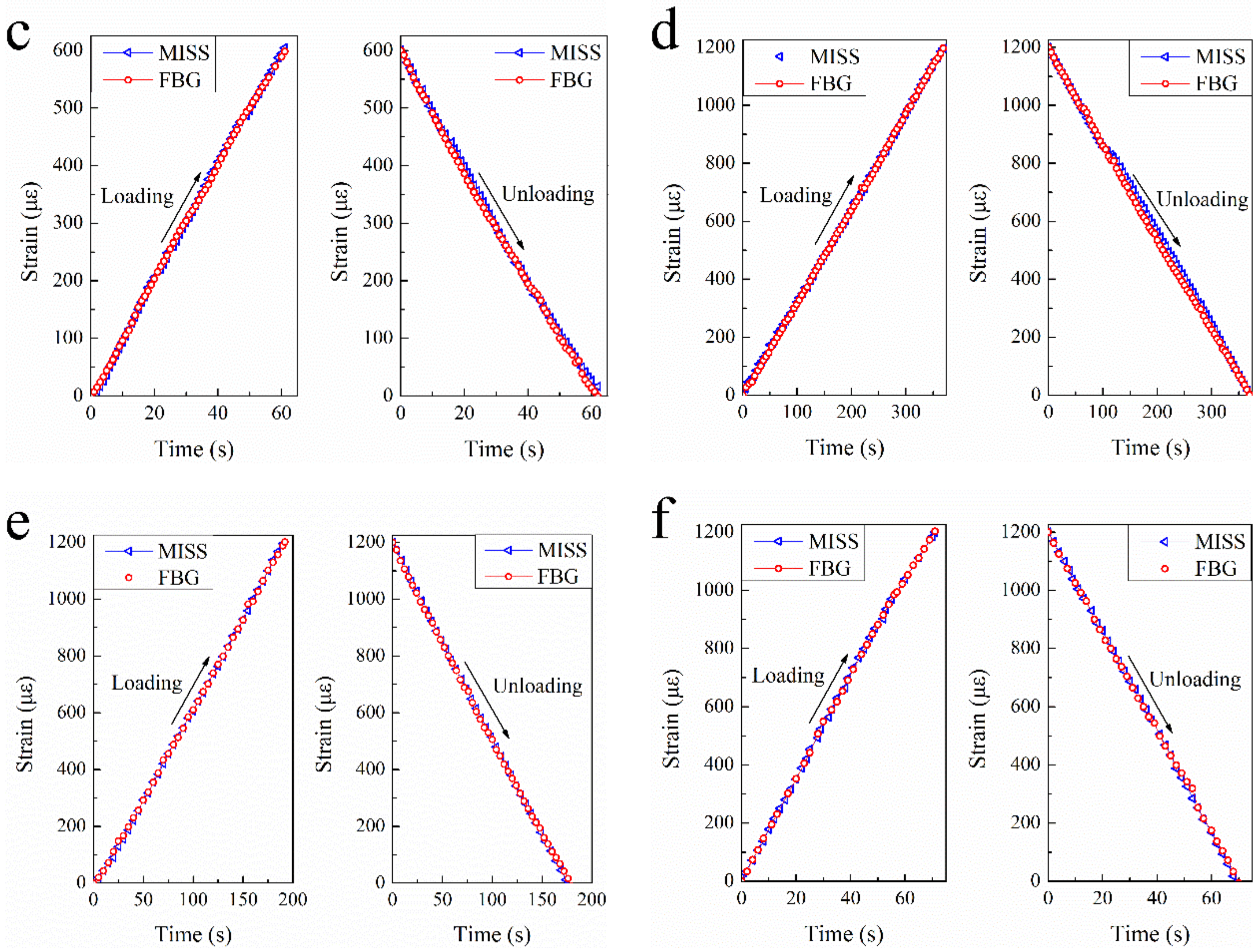
Metal tensile tests were carried out on various materials, loading speeds, and loading methods. It was found that the material of specimen and loading speeds had little effect on the measurement results. Under the two loading methods of graded loading and continuous loading, the MISS sensor can obtain the strain value of the specimens effectively. In the metal tensile test, the mean error is 7.1 με and the correlation coefficient is as high as 0.9997 between the FBG sensor and the MISS sensor measure results.
2.
The strain measurement of the pure bending section of the RC beam further verified the effectiveness of the MISS sensor. The mean relative error of strain values is 2.5% in the reinforced concrete beam bending test.
The MISS sensor is fixed on the structure, the mobile phone is connected to the MISS sensor when measuring the strain, and the smartphone can be removed during the non-measuring process. The strain images acquired by smartphones can be collated, transmitted, and archived by various means such as WIFI and Bluetooth, which is a low-cost, portable, and fast means of strain measurement and can be commonly used in practical engineering. Note that the MISS sensor was coupled with a smartphone in this research. However, in the case of citizen-participated structural strain measurement, it is necessary to study the synergistic work between the different actors. Besides, the next task is to make full use of the advantages of the MISS sensors to establish a public-participatory strain monitoring platform.

Author Contributions

Conceptualization, X.C. and X.Z.; methodology, X.C.; software, L.Z.; validation, X.C., B.X. and X.Z.; formal analysis, X.C.; investigation, G.Z.; resources, G.Z.; data curation, X.C.; writing—original draft preparation, X.C.; writing—review and editing, X.C. and X.Z.; visualization, L.Z.; supervision, B.X.; project administration, X.Z.; funding acquisition, X.Z. and G.Z. All authors have read and agreed to the published version of the manuscript.

Funding

This research was funded by the China Construction Eighth Engineering Division Corp., LTD 2021 Technology R&D Project (20210307).

Institutional Review Board Statement

Not applicable.

Informed Consent Statement

Not applicable.

Data Availability Statement

Some or all data that support the findings of this study are available from the corresponding author upon reasonable request.

Conflicts of Interest

The authors declare no conflict of interest.

References

  1. Zhang, J.; Guo, S.L.; Wu, Z.S.; Zhang, Q.Q. Structural identification and damage detection through long-gauge strain measurements. Eng. Struct. 2015, 99, 173–183. [Google Scholar] [CrossRef]
  2. Scott, R.H.; Banerji, P.; Chikermane, S.; Srinivasan, S.; Basheer, P.A.M.; Surre, F.; Sun, T.; Grattan, K.T.V. Commissioning and Evaluation of a Fiber-Optic Sensor System for Bridge Monitoring. IEEE Sens. J. 2013, 13, 2555–2562. [Google Scholar] [CrossRef] [Green Version]
  3. Zhang, S.Y.; Liu, Y. Damage detection of bridges monitored within one cluster based on the residual between the cumulative distribution functions of strain monitoring data. Struct. Health Monit. 2020, 19, 1764–1789. [Google Scholar] [CrossRef]
  4. Tung, S.T.; Yao, Y.; Glisic, B. Sensing sheet: The sensitivity of thin-film full-bridge strain sensors for crack detection and characterization. Meas. Sci. Technol. 2014, 25, 075602. [Google Scholar] [CrossRef]
  5. Chung, D.D.L. Structural health monitoring by electrical resistance measurement. Smart Mater. Struct. 2001, 10, 624–636. [Google Scholar] [CrossRef]
  6. Ajovalasit, A. The Measurement of Large Strains Using Electrical Resistance Strain Gages. Exp. Tech. 2012, 36, 77–82. [Google Scholar] [CrossRef]
  7. dos Reis, J.; Costa, C.O.; da Costa, J.S. Strain gauges debonding fault detection for structural health monitoring. Struct. Control Health Monit. 2018, 25, e2264. [Google Scholar] [CrossRef]
  8. Feng, X.; Zhou, J.; Sun, C.; Zhang, X.; Ansari, F. Theoretical and Experimental Investigations into Crack Detection with BOTDR-Distributed Fiber Optic Sensors. J. Eng. Mech. 2013, 139, 1797–1807. [Google Scholar] [CrossRef]
  9. Ramakrishnan, M.; Rajan, G.; Semenova, Y.; Farrell, G. Overview of Fiber Optic Sensor Technologies for Strain/Temperature Sensing Applications in Composite Materials. Sensors 2016, 16, 99. [Google Scholar] [CrossRef] [Green Version]
  10. Kerrouche, A.; Boyle, W.J.O.; Sun, T.; Grattan, K.T.V. Design and in-the-field performance evaluation of compact FBG sensor system for structural health monitoring applications. Sens. Actuators A-Phys. 2009, 151, 107–112. [Google Scholar] [CrossRef]
  11. Di Sante, R. Fibre Optic Sensors for Structural Health Monitoring of Aircraft Composite Structures: Recent Advances and Applications. Sensors 2015, 15, 18666–18713. [Google Scholar] [CrossRef]
  12. Lee, H.M.; Choi, S.W.; Jung, D.-J.; Park, H.S. Analytical Model for Estimation of Maximum Normal Stress in Steel Beam-Columns Based on Wireless Measurement of Average Strains from Vibrating Wire Strain Gages. Comput.-Aided Civ. Infrastruct. Eng. 2013, 28, 707–717. [Google Scholar] [CrossRef]
  13. Lee, H.M.; Kim, J.M.; Sho, K.; Park, H.S. A wireless vibrating wire sensor node for continuous structural health monitoring. Smart Mater. Struct. 2010, 19, 055004. [Google Scholar] [CrossRef]
  14. Pan, B.; Qian, K.; Xie, H.; Asundi, A. Two-dimensional digital image correlation for in-plane displacement and strain measurement: A review. Meas. Sci. Technol. 2009, 20, 062001. [Google Scholar] [CrossRef]
  15. Kang, J.; Ososkov, Y.; Embury, J.D.; Wilkinson, D.S. Digital image correlation studies for microscopic strain distribution and damage in dual phase steels. Scr. Mater. 2007, 56, 999–1002. [Google Scholar] [CrossRef]
  16. Munoz, H.; Taheri, A.; Chanda, E.K. Pre-Peak and Post-Peak Rock Strain Characteristics During Uniaxial Compression by 3D Digital Image Correlation. Rock Mech. Rock Eng. 2016, 49, 2541–2554. [Google Scholar] [CrossRef]
  17. Pan, B. Digital image correlation for surface deformation measurement: Historical developments, recent advances and future goals. Meas. Sci. Technol. 2018, 29, 082001. [Google Scholar] [CrossRef]
  18. Bermudo Gamboa, C.; Martin-Bejar, S.; Trujillo Vilches, F.J.; Castillo Lopez, G.; Sevilla Hurtado, L. 2D-3D Digital Image Correlation Comparative Analysis for Indentation Process. Materials 2019, 12, 4156. [Google Scholar] [CrossRef] [Green Version]
  19. Sivasuriyan, A.; Vijayan, D.S.; Gorski, W.; Wodzynski, L.; Vaverkova, M.D.; Koda, E. Practical Implementation of Structural Health Monitoring in Multi-Story Buildings. Buildings 2021, 11, 263. [Google Scholar] [CrossRef]
  20. Tondolo, F.; Matta, E.; Quattrone, A.; Sabia, D. Experimental test on an RC beam equipped with embedded barometric pressure sensors for strains measurement. Smart Mater. Struct. 2019, 28, 055040. [Google Scholar] [CrossRef]
  21. Gregori, A.; Di Giampaolo, E.; Di Carlofelice, A.; Castoro, C. Presenting a New Wireless Strain Method for Structural Monitoring: Experimental Validation. J. Sens. 2019, 2019, 5370838. [Google Scholar] [CrossRef]
  22. Morgese, M.; Domaneschi, M.; Ansari, F.; Cimellaro, G.P.; Inaudi, D. Improving Distributed Fiber-Optic Sensor Measures by Digital Image Correlation: Two-Stage Structural Health Monitoring. ACI Struct. J. 2021, 118, 91–102. [Google Scholar]
  23. Alavi, A.H.; Jiao, P.; Buttlar, W.G.; Lajnef, N. Internet of Things-enabled smart cities: State-of-the-art and future trends. Measurement 2018, 129, 589–606. [Google Scholar] [CrossRef]
  24. Grossi, M. A sensor-centric survey on the development of smartphone measurement and sensing systems. Measurement 2019, 135, 572–592. [Google Scholar] [CrossRef]
  25. Vittorio, A.; Rosolino, V.; Teresa, I.; Vittoria, C.M.; Vincenzo, P.G. Automated sensing system for monitoring of road surface quality by mobile devices. Procedia-Soc. Behav. Sci. 2014, 111, 242–251. [Google Scholar] [CrossRef] [Green Version]
  26. Ozer, E.; Feng, M.Q. Synthesizing spatiotemporally sparse smartphone sensor data for bridge modal identification. Smart Mater. Struct. 2016, 25, 085007. [Google Scholar] [CrossRef]
  27. Zhao, X.; Han, R.; Ding, Y.; Yu, Y.; Guan, Q.; Hu, W.; Li, M.; Ou, J. Portable and convenient cable force measurement using smartphone. J. Civ. Struct. Health Monit. 2015, 5, 481–491. [Google Scholar] [CrossRef]
  28. Zhao, X.; Liu, H.; Yu, Y.; Zhu, Q.; Hu, W.; Li, M.; Ou, J. Displacement monitoring technique using a smartphone based on the laser projection-sensing method. Sens. Actuators A-Phys. 2016, 246, 35–47. [Google Scholar] [CrossRef]
  29. Jo, B.-W.; Lee, Y.-S.; Jo, J.H.; Khan, R.M.A. Computer Vision-Based Bridge Displacement Measurements Using Rotation-Invariant Image Processing Technique. Sustainability 2018, 10, 1785. [Google Scholar] [CrossRef] [Green Version]
  30. Yu, L.P.; Lubineau, G. A smartphone camera and built-in gyroscope based application for non-contact yet accurate off-axis structural displacement measurements. Measurement 2021, 167, 108449. [Google Scholar] [CrossRef]
  31. Zhang, Y.; Liu, P.; Zhao, X. Structural displacement monitoring based on mask regions with convolutional neural network. Constr. Build. Mater. 2021, 267, 120923. [Google Scholar] [CrossRef]
  32. Oraczewski, T.; Staszewski, W.J.; Uhl, T. Nonlinear acoustics for structural health monitoring using mobile, wireless and smartphone-based transducer platform. J. Intell. Mater. Syst. Struct. 2016, 27, 786–796. [Google Scholar] [CrossRef]
  33. Wang, N.; Zhao, X.; Zhao, P.; Zhang, Y.; Zou, Z.; Ou, J. Automatic damage detection of historic masonry buildings based on mobile deep learning. Autom. Constr. 2019, 103, 53–66. [Google Scholar] [CrossRef]
  34. Ratnam, M.M.; Ooi, B.Y.; Yen, K.S. Novel moire-based crack monitoring system with smartphone interface and cloud processing. Struct. Control Health Monit. 2019, 26, e2420. [Google Scholar] [CrossRef]
  35. Dzeng, R.-J.; Fang, Y.-C.; Chen, I.C. A feasibility study of using smartphone built-in accelerometers to detect fall portents. Autom. Constr. 2014, 38, 74–86. [Google Scholar] [CrossRef]
  36. Akhavian, R.; Behzadan, A.H. Smartphone-based construction workers’ activity recognition and classification. Autom. Constr. 2016, 71, 198–209. [Google Scholar] [CrossRef]
  37. Zhang, M.Y.; Cao, T.Z.; Zhao, X.F. Using Smartphones to Detect and Identify Construction Workers’ Near-Miss Falls Based on ANN. J. Constr. Eng. Manag. 2019, 145, 04018120. [Google Scholar] [CrossRef]
  38. Yu, L.P.; Pan, B. In-plane displacement and strain measurements using a camera phone and digital image correlation. Opt. Eng. 2014, 53, 054107. [Google Scholar] [CrossRef]
  39. Xie, B.; Chen, X.; Ding, M.; Zhou, G.; Zhao, X. Design and development of a new strain measuring method based on smartphone and machine vision. Measurement 2021, 182, 109724. [Google Scholar] [CrossRef]
  40. Bay, H.; Ess, A.; Tuytelaars, T.; Van Gool, L. Speeded-Up Robust Features (SURF). Comput. Vis. Image Underst. 2008, 110, 346–359. [Google Scholar] [CrossRef]
  41. Wang, H.; Mirota, D.; Hager, G.D. A Generalized Kernel Consensus-Based Robust Estimator. IEEE Trans. Pattern Anal. Mach. Intell. 2010, 32, 178–184. [Google Scholar] [CrossRef] [Green Version]
Figure 1. Schematic illustration of the MISS sensor. (a) Overall appearance of the sensor; (b) Photograph of the MISS sensor; (c) Image captured by smartphone.
Buildings 12 00212 g001aBuildings 12 00212 g001b
Figure 2. The process of feature point calculation.
Buildings 12 00212 g002
Figure 3. Schematic of fixing device.
Buildings 12 00212 g003
Figure 4. Coordinate map of relative displacement.
Buildings 12 00212 g004
Figure 5. Image processing. (a) Full image acquired using a smartphone; (b) Extraction of the marked circle.
Buildings 12 00212 g005
Figure 6. Schematic diagram of the metal tensile test.
Buildings 12 00212 g006
Figure 7. Detailed diagram of the metal tensile test. (a) Photos of t the installation of the sensors; (b) Schematic diagram of the installation of the sensors; (c) Technical diagram of the metal specimen.
Buildings 12 00212 g007
Figure 8. Schematic diagram of the RC beam test.
Buildings 12 00212 g008
Figure 9. Detailed diagram of the reinforced concrete beam test. (a) Photo of the test setup; (b) Detailed photo of the sensors mounted on the RC beam; (c) Photo of cracks in the measurement region; (d) Reinforcement diagram of RC beam.
Buildings 12 00212 g009
Figure 10. Comparison of the FBG sensor and the MISS sensor results under staged loading. (a) Steel specimen; (b) Aluminum specimen.
Buildings 12 00212 g010
Figure 11. Comparison of the FBG sensor and the MISS sensor results under continuous loading. (a) Steel specimen loaded at 0.1 mm/min; (b) Steel specimen loaded at 0.2 mm/min; (c) Steel specimen loaded at 0.5 mm/min; (d) Aluminum specimen loaded at 0.1 mm/min; (e) Aluminum specimen loaded at 0.2 mm/min; (f) Aluminum specimen loaded at 0.5 mm/min.
Buildings 12 00212 g011aBuildings 12 00212 g011b
Figure 12. Stain measurement results of the bending test. (a) Load–strain curve; (b) Bending test error.
Buildings 12 00212 g012
Table 1. Rear camera parameters in the Honor 7x.
ParametersPerformance Indicators
Sensor typeCMOS
FlashlightThe LED light
Effective pixels16 MP
Picture max resolution4608 × 3456 pixel
Video shooting1080 P (30 frames/sec)
Table 2. Staged loading test conditions.
Test CaseSpecimen MaterialLoading ProcessLoad (kN)
1SteelStaged loading10
2AluminumStaged loading10
Table 3. Continuous loading test conditions.
Test CaseSpecimen MaterialLoading ProcessLoading Rate
(mm/min)
1SteelContinuous loading0.1
2SteelContinuous loading0.2
3SteelContinuous loading0.5
4AluminumContinuous loading0.1
5AluminumContinuous loading0.2
6AluminumContinuous loading0.5
Table 4. Continuous loading test conditions result of the two types of data.
Test CaseSpecimen MaterialLoading Rate
(mm/min)
Mean Error
(με)
Correlation Coefficient
1Steel0.15.40.9998
2Steel0.25.00.9998
3Steel0.54.20.9997
4Aluminum0.17.60.9998
5Aluminum0.211.10.9998
6Aluminum0.59.30.9996
Publisher’s Note: MDPI stays neutral with regard to jurisdictional claims in published maps and institutional affiliations.

