Article

Numerical Analysis of Different Influencing Factors on the In-Plane Failure Mode of Unreinforced Masonry (URM) Structures

School of Civil Engineering, Xi’an University of Architecture and Technology, Xi’an 710055, China
*
Author to whom correspondence should be addressed.
Buildings 2022, 12(2), 183; https://doi.org/10.3390/buildings12020183
Submission received: 11 January 2022 / Revised: 29 January 2022 / Accepted: 1 February 2022 / Published: 5 February 2022

Abstract

:
The research work herein presented is aimed at investigating the effects of different influencing factors on the in-plane failure mode of unreinforced masonry (URM) structures. Firstly, the in-plane stress failure criterion cited in this paper was introduced, and the corresponding judgment procedure was demonstrated. Then, various finite element models considering different influencing factors were established, which included the aspect ratio of pier (η), stiffness ratio of pier to spandrel (ρ) and vertical load (σ). Furthermore, the in-plane stress failure criterion that we introduced was used to evaluate the failure modes of each model. The main findings of the simulations were as follows: under the condition of (η ≤ 1.0), three failure modes emerged in all models, which included pier, mixed and spandrel failure modes, with the gradual increase in ρ. Once the value of η exceeded 1.0, all models exhibited the pier failure mode regardless of whether the value of ρ increased or decreased. Moreover, under the identical aspect ratio (η = 1.0), the failure modes of the models altered regularly with the increase in the value of σ (from 0.3 MPa to 0.6 MPa), which transferred from pier failure to mixed failure, and from mixed failure to spandrel failure. The research results not only provide theoretical reference for the design of new masonry buildings, but also provide technical guidance for the judgement and prediction of failure modes of existing masonry buildings.

1. Introduction

As one of the common structural types in the field of civil engineering, unreinforced masonry (URM) structure has the characteristics of high occupancy rate, diverse construction styles and convenient construction, which leads to the prevalence of building URM buildings in developing countries and remote towns [1,2]. However, some URM buildings with poor seismic performance experience and cause serious damage, even if they are subjected to small and moderate seismic action [3,4].
During an earthquake, due to the gravity load, URM walls are often subjected to out-of-plane action, in-plane action and combined action of out-of-plane and in-plane [5,6,7]. The post-earthquake surveys display that the out-of-plane collapse of URM infill walls is critical even for new buildings designed to resist earthquakes, resulting in casualties and economic losses. Review and experimental study on the out-of-plane response and influence parameters of URM filled walls have been carried out in the literature [8,9], in order to evaluate the contribution of various parameters to the out-of-plane behavior of URM walls. Usually, URM walls are mainly subjected to in-plane action, which is characterized by the combination of gravity and horizontal loads (wind or earthquake) [10]. Moreover, masonry is regarded as a typical brittle anisotropic material that displays obvious directional properties [11], such as composite structure and the inherent weak direction [10].
At present, theoretical and experimental research on the anisotropic behavior of masonry remain to be carried out, resulting in insufficient knowledge on the mechanical properties of masonry. Furthermore, the inherent anisotropy characteristics lead to the research under bi-axial stress of masonry being more complex and uncontrollable. Generally, the failure of masonry walls may emerge alone in the joints or simultaneously in the joints and blocks according to the direction of the joints in relation to the stress directions [11].
Considering the complexity and uncertainty of masonry anisotropic, the calculation model describing the failure surface of masonry is regarded as one of the effective methods to investigate the mechanical behavior of masonry [11]. On this foundation, partial criteria for masonry structures have been proposed [12,13,14,15], and corresponding experimental investigations have been performed [16,17,18,19,20,21]. This kind of test is mainly carried out on the disc device, and the vertical load applied by the disc on the masonry produces the tensile stress of the mortar joints [11]. In order to master the mechanical behavior of masonry under both compressive stress and tensile stress, an improved device to test the tensile performance of masonry is proposed, which simplifies various complex stress into the mechanical response between the angle of mortar joints and the ratio of bi-axial principal stress. By combining 58 bi-axial stress (tensile and compressive) findings with previous research results, the in-plane stress failure criterion of masonry was established [22].
The cracking time of masonry walls under various stress states can be determined by means of in-plane stress failure criterion. The stress state of any part in the wall can be simulated by the equivalent stress element, and the stress value of the main stress element at different parts and the angle of mortar joints (between the principal stress and the normal stress) are closely related. Once the in-plane stress value of a certain part exceeds the corresponding limit value, the wall will reach the cracking state [23].
In recent years, the mechanical response of URM walls has been gradually simulated and analyzed with the help of various finite element software [24,25,26]. In view of the complexity of masonry mechanics, different methods, characterization scales and analysis strategies of masonry mechanical behavior have been proposed. Popular modeling strategies are divided into four categories: the block-based model, the continuous-medium model, the geometry-based model and the macro-element model [27]. This classification can not only reasonably rank many research results in the field of masonry structures, but also provide guidance for scholars to select appropriate numerical models.
As we all know, the failure modes of URM walls are mainly divided into three types: pier failure, spandrel failure and mixed failure [6,28,29]. However, in the current masonry structures design code [30], spandrel is regarded as a continuous-wall strip and is considered not to be damaged under the seismic action; also, masonry structures are equivalent to a frame structure composed of bar elements [31], and in the bar system only flexural deformation occurs. These conclusions are inconsistent with the actual seismic damage results. Three failure modes may occur once the in-plane stress value of a certain part exceeds the corresponding limit value. Traditionally, the macro method of determining failure modes may have some defects, such as imprecision and subjective consciousness. After using the in-plane stress criterion, the failure mode of masonry can be determined more accurately.
In addition, relevant conclusions have been drawn that the in-plane seismic performance is closely related to the damage degree of the pier and spandrel under the earthquake [26,28,29]. If the damage degree of pier exceeds that of spandrel, the failure mode is regarded as “strong spandrel and weak pier”, which leads to serious damage or even complete collapse of masonry structures. On the contrary, if the damage degree of spandrel exceeds that of pier, the failure mode is regarded as “strong pier and weak spandrel”, which encourages spandrel to participate in the deformation and energy dissipation of masonry structures in advance [1,28]. Meanwhile, many theoretical analysis and experimental investigation have also been carried out [32,33,34,35,36,37].
Against this background, the numerical simulation of masonry failure mode using in-plane stress failure criterion were investigated. The paper has the following structure. Section 2 introduces how to use in-plane stress failure criterion and exhibits specific cases. Section 3 explains the details of the finite-element model. In Section 4, the judgment method in Section 2 is used to discuss the similarities and differences of failure modes of masonry wall under the different influencing factors, including aspect ratio of pier, stiffness ratio of pier to spandrel and vertical load of the wall. Finally, some definite conclusions were obtained, and therefore some suggestions on the design and retrofitting of masonry wall are proposed.

2. Judgement of Failure Mode of Masonry

2.1. Judgement Procedures of Failure Mode

In terms of the stress distribution regulation of the masonry wall, the horizontal stress (σx) and shear stress (τxy) in the core area are always greater than those in the edge area no matter in pier or spandrel [23]. Therefore, the core area of the pier and/or spandrel is selected as the area to extract the stress value. The in-plane stress failure criterion proposed in reference [22] is used to determine the failure mode of the masonry wall.
Firstly, the horizontal stress (σx), vertical stress (σy) and shear stress (τxy) at the required position are extracted from the finite element simulation results. Secondly, Formulas (1)–(3) [23] are applied to calculate the principal stress σ1 and σ3, and the values of σ1* and σ3* are obtained after standardizing the values of σ1 and σ3. Finally, the values (σ1^) in different quadrants are calculated by Formulas (4)–(6) [22]; the values of σ1* and σ1^ are compared, and the position where the failure occurs first can be determined. Similarly, by comparing the values of σ1* and σ1^ in the core area of the pier and the spandrel at the same time, the failure modes of the masonry wall can be determined; and, failure modes are defined as the following three types: pier failure mode, spandrel failure mode and mixed failure mode.
σ 1 = ( σ x + σ y ) 2 + ( σ x σ y ) 2 4 + τ x y 2 ,
σ 3 = ( σ x + σ y ) 2 ( σ x σ y ) 2 4 + τ x y 2 ,
t a n 2 α = 2 τ x y ( σ x σ y ) ,
36.36 σ 1 ^ 2 60.23 σ 3 ^ 2 + 37.41 σ 1 ^ + 21.51 σ 3 ^ + 49.25 σ 1 σ 1 = 1 ,
σ 1 ^ 20.83 σ 3 ^ = 1 ,
σ 1 ^ = ( 7.09 θ 2 + 11.14 θ 2.60 ) σ 3 ^ 2 + ( 2.181 θ 2 3.424 θ + 0.864 ) σ 3 ^ 0.022 ,

2.2. Analysis for Specific Case

The data cited in the case is shown in Table 1. The stress value of the spandrel and the pier core areas were extracted from the numerical simulation results. In terms of the comparison of the data in Table 1, the horizontal stress (σx) of the spandrel was significantly higher than the vertical stress (σy) of the spandrel, the vertical stress (σy) of the pier was obviously higher than the horizontal stress (σx) of the pier and the shear stress (τxy) of the pier was almost equal to that of the spandrel. These conclusions were consistent with the disaster phenomenon in the actual earthquake.
Judgement procedures of failure mode are as follows:
Step 1: principal stress values of the spandrel and pier (σ1 and σ3) were calculated according to Formulas (1)–(3).
σ1(spandrel) = −0.022040, σ3(spandrel) = 0.194796
σ1(pier) = −0.344716, σ3(pier) = 0.001816
Step 2: normalized principal stress values of the spandrel and pier (σ1* and σ3*)* were obtained.
σ1*(spandrel) = −0.001469, σ3*(spandrel) = 0.129864
σ1*(pier) = 0.229831, σ3*(pier) = −0.001210
Step 3: the values (σ1^(spandrel, pier)) in different quadrants were calculated by Formulas (4)–(6), and the corresponding stress values (σ1^ and σ1*) were compared.
σ1^(spandrel) = 0.221431, σ1^(pier) = 0.974785
σ1^(spandrel) = 0.221431 > σ1*(spandrel) = −0.001469
σ1^(pier) = 0.974785 > σ3*(pier) = 0.229831
Step 4: judgement of failure mode of the masonry wall.
When the time the spandrel principal stress exceeded the corresponding envelope was earlier than the time when the pier principal stress exceeded the corresponding envelope, then the wall was considered to be in spandrel failure mode. In the opposite situation, the wall was considered to be in pier failure mode. The comparison results of this case exhibited that spandrel failure mode occurred in the masonry wall.

3. Main Factors Affecting Failure Mode: Numerical Simulation
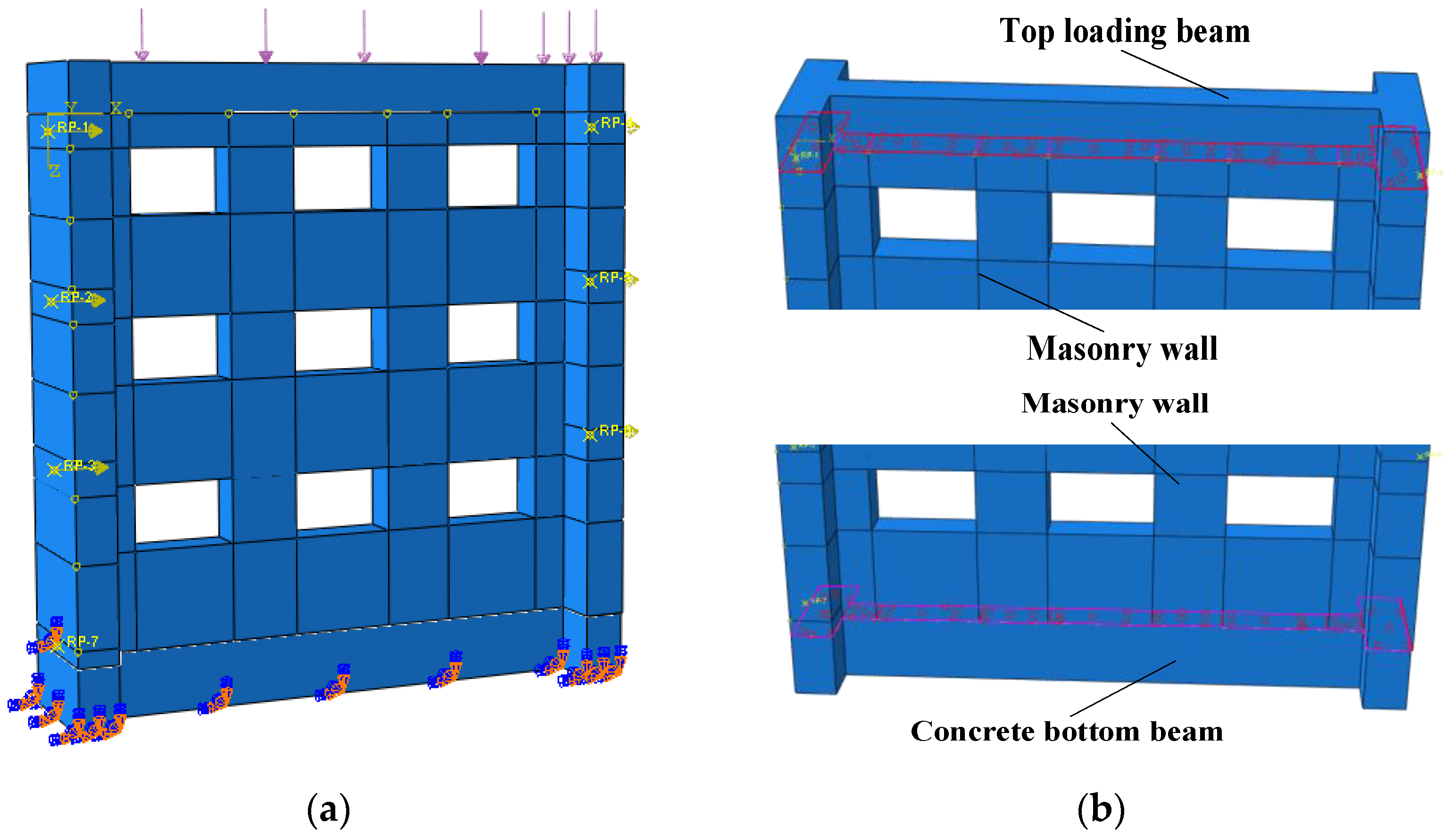
Three main factors affecting the failure modes of masonry walls are summarized in the literature [23], including aspect ratio of pier, stiffness ratio of pier to spandrel and vertical load applied to wall. In this chapter, the in-plane quasi-static numerical simulation of masonry wall was performed by using the control-variation method, in order to discuss the influence degree and regulation of the changes of the above factors on the masonry failure mode.
ABAQUS was used as the simulation software because of its significant advantages in dealing with nonlinear problems, and ABAQUS/Standard was used as the solver thanks to its high calculation accuracy. According to the test setup described in the literature [2,23], all finite-element models (FEMs) were composed of a concrete-bottom beam, a brick-masonry wall and a top-loading beam. The masonry elements were described in the form of three-dimensional solid and eight-node brick elements provided in ABAQUS/Standard element library (C3D8R type). Although there was no plastic damage model for masonry materials in ABAQUS, the concrete plastic damage model could be used to replace the plastic damage model of masonry. This was based on a fact that masonry belonged to brittle materials and the damage of brittle materials could be replaced by the concrete damage model.

3.1. Model Design

In accordance with the analysis of the literature on masonry structures [1,2,7,34,38], the stiffness ratio of pier to spandrel of design of masonry walls was in the range of 0.4–2.0. Considering the various sizes of the pier and spandrel in the existing masonry structures, 21 models with different aspect ratio of pier and stiffness ratio of pier to spandrel were designed. Pier dimensions of M1, M2 and M3 (width (mm) × height (mm)) were 1800 × 1500, 1500 × 1500 and 1000 × 1800, and the corresponding aspect ratios of piers were 0.8, 1.0 and 1.8. Under the identical aspect ratio, seven models (1–7) with different stiffness ratios were designed. The partial design parameters of models are displayed in Table 2, and corresponding finite element models are shown in Figure 1.

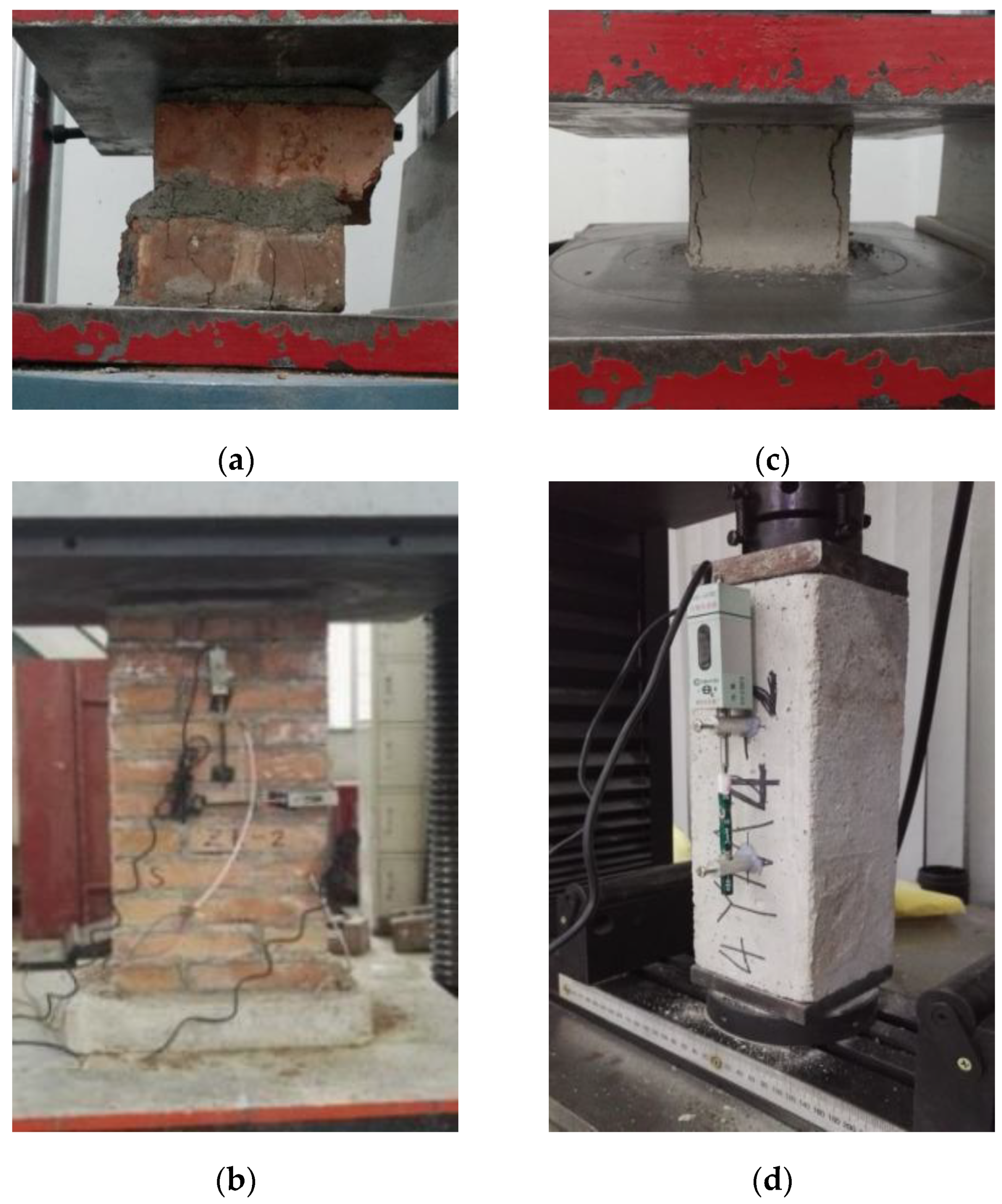
3.2. Mechanical Parameters

The uniaxial compression constitutive of masonry is shown in Formula (7) [39]. σ and ε represented the values of stress and strain of masonry, respectively; fm represented the stress value of the compressive stress–strain relationship of masonry at the peak point and εm represented the strain value of the corresponding point; the value of εm was 1.633. The tensile constitutive model of concrete was used to replace the tensile constitutive model of masonry, as shown in Formulas (8) and (9) [23,40]. ftm represented the stress value of the tensile stress–strain relationship of masonry at the peak point and εtm represented the strain value of the corresponding point.
σ f m = η 1 + ( η 1 ) ( ε ε m ) η η 1 ε ε m ,
σ f t m = ε ε t m ,   x 1 ,
σ f t m = ε ε t m 2 ( ε ε t m 1 ) 1.7 + ε ε t m , x > 1 ,
The main data input into the concrete plastic damage model are as follows: 30 (expansion angle), 0.1 (eccentricity), 1.16 (fb0/fc0), 0.6667 (K) and 0.005 (viscosity coefficient). Moreover, the mean compressive strength of the bricks was obtained from compression tests conducted on 10 samples according to GB/T 2542–2012 [41] and the obtained value was 17.8 MPa (the coefficient of variation (COV) = 0.29). Correspondingly, the mean compressive strength of the mortar was determined by testing nine mortar cubes with the dimensions of 70.7 mm on each face and the obtained value was 8.64 MPa according to GB/T 25181–2019 [42] (COV = 0.14). The key parameters obtained from testing brick masonry are as follows: 2248 kg/m3 (density), 2400 MPa (elastic modulus) and 0.149 (Poisson’s ratio). The testing of mechanical properties of brick, mortar and masonry is shown in Figure 2.

3.3. Constraints and Interactions

The structural interaction between masonry wall and the concrete beams (bottom and top) was achieved by means of rigid connections (surface-to-surface tie constraints), which was able to prevent possible relative displacements and rotations between the interested nodes [43]. The models of FEMs were rigidly restrained at the bottom position (ux = uy = uz = 0). The loading beam was first subjected to vertical load, and then transmitted the vertical load to the model itself.
In the damaged masonry buildings that have been investigated, the precast floor slabs had no significant effect on the seismic performance of the integral wall [44]. Usually, the precast floor slab and adjacent walls are subjected to the same lateral force, resulting in the same deformation. Figure 3 exhibited the current situation of energy dissipation and deformation of the precast floor slab and spandrel in earthquake. Therefore, the contribution of precast floor slabs in all models was ignored, and the floor slab and spandrel were regarded as integral components.

3.4. Load Actions

Based on the relevant provisions of GB 50009–2012 [45], the vertical load of traditional masonry structures was calculated by considering the floor’s live load and the dead weight of wall and floor. The vertical load of each floor was about 100 kPa (0.1 MPa). In many remote towns and areas, low-story masonry buildings ware usually 2–3 floors, and the minimum vertical load applied to the model was determined (σ = 0.3 MPa). Moreover, multi-story masonry buildings were usually 5–6 floors, and the maximum vertical load applied to the model was determined (σ = 0.6 MPa). Typical damaged masonry buildings are exhibited in Figure 4.

4. Discussion of Numerical Results

The in-plane stress failure criterion in this paper has been cited in Section 2.1, and the judgment process of specific cases has been introduced in Section 2.2. In this section, the location of obtaining various stress values was consistent with that described in Section 2.2, which was the center point of the spandrel on the second floor and pier on the first floor. The judgement procedures of failure modes were consistent with those described in Section 2.2, which mainly included four steps. Numerical results and failure modes of all models were discussed in Section 4.1 and Section 4.2.

4.1. Effects of Aspect Ratio and Stiffness Ratio

The comparison of the simulation results of some models is shown in Figure 5. The simulation results of M1 were not exhibited in here, because the contour plot of M1 was similar to that of M2. Furthermore, the comparison of failure modes of all models determined by in-plane stress failure criterion are shown in Table 3.
In general, the stress nephogram of the six models showed that the stress at the pier was higher than that at the spandrel, as shown in Figure 5a–f. At the same time, the stress value of each model gradually decreased from first floor to third floor, demonstrating the fact that the damage degree of masonry wall gradually weakened from the bottom floor to the top floor [2,7]. Moreover, the location of stress concentration was mainly concentrated at the edge of the openings, manifesting that the edge of the openings was the location where stress concentration emerged earlier. This phenomenon was consistent with the conventional cognition that the cracks and damage of masonry walls generally formed at the edge of the openings and further elongated and widened [1,7,23,29,46].
Furthermore, the following conclusions can be found by comparing the models in Figure 5. The stress of each model emerged at the edge of the bottom floor and gradually expanded to the top floor along the diagonal direction. Although the location of the maximum stress of each model was different, the overall developing trend of the stress nephogram tended to be consistent, which illustrated the effectiveness of using the bottom shear method to simulate in-plane action of masonry walls. More severe damage was observed in pier rather than spandrel, as shown in Figure 5a,d,f. However, it was difficult to evaluate the damage of other models because the stress values of pier and spandrel at the bottom floor were not significantly different, as shown in Figure 5b,c,e. In order to more accurately quantify the stress values of pier and spandrel at the specific locations, it was necessary to judge the damage and failure mode of the model through the in-plane stress failure criterion proposed in Section 2.
In terms of the comparison of the results in Table 3, the following regulations could be found. In general, all models mainly showed three failure modes, named as pier failure mode, mixed failure mode and spandrel failure mode. The failure modes of all models of M1 and M2 were similar, which was related to the approximate aspect ratio of piers of M1 (η = 0.8) and M2 (η = 1.0). Pier failure mode emerged in all models (M1, M2 and M3), when the stiffness ratio of pier to spandrel was less than 1.0 (ρ < 1.0). Furthermore, the failure modes of M1 and M2 transferred from pier failure mode to mixed failure mode, and from mixed failure mode to spandrel failure mode, with the increase in the stiffness ratio of pier to spandrel (1.0 ≤ ρ ≤ 2.0). However, it is worth noting that all models of M3 only occurred the pier failure mode, whether the stiffness ratio of pier to spandrel increased or decreased (from 0.5 to 1.0). It can be inferred that, under the condition of larger aspect ratio of the pier (η = 1.8), the cracking and damage of masonry structures were mainly concentrated in the pier, and it was unlikely to transfer from the pier to the adjacent spandrel, resulting in the gradual aggravation of pier damage until the failure of the overall structures.
According to the research conclusions in the literature [1,2,28], pier failure mode was viewed as “strong spandrel and weak pier”, which led to serious damage or even complete collapse of masonry structures. Spandrel failure mode was viewed as “strong pier and weak spandrel”, which caused spandrel to participate in the deformation and energy dissipation of masonry structures in advance. Therefore, the aspect ratio of pier (η) and stiffness ratio of pier to spandrel (ρ) should be limited in the design of masonry structures in order to emerge a reasonable failure mechanism as much as possible. Combined with the research findings of simulation and related literature, the aspect ratio of the pier of masonry structures should not exceed 1.0 (η ≤ 1.0), and the stiffness ratio of pier to spandrel should be in the range of 1.0–2.0 (1.0 ≤ ρ ≤ 2.0).

4.2. Effects of Vertical Load

In order to further investigate the effect of vertical load on the failure modes of masonry structures, the simulation of M2 models (η = 1.0) with different vertical load was carried out. According to the statement in Section 3.4, the objective models were applied with vertical loads of 0.3 MPa and 0.6 MPa, respectively, and the corresponding data were extracted from the simulation results. The comparison of failure modes of all models determined by in-plane stress failure criterion are exhibited in Table 4.
In general, two failure modes, mixed failure mode and spandrel failure mode, are mainly presented in Table 4. Under the identical aspect ratio of pier (η = 1.0), the failure modes of the models altered regularly with the increase in vertical load (from 0.3 MPa to 0.6 MPa), which transferred from pier failure to mixed failure, and from mixed failure to spandrel failure. The failure modes of the two models with stiffness ratio of pier to spandrel less than (ρ < 1.0) transferred from pier failure to mixed failure, with the increase in vertical load from 0.3 MPa to 0.6 MPa. The failure mode of the two models with stiffness ratios of pier to spandrel between (1.25 ≤ ρ ≤ 2.5) transferred from mixed failure to spandrel failure, as the vertical load increased from 0.3 MPa to 0.6 MPa. The altering of failure mode did not emerge in the observation of other models.
Through the analysis of the simulation results, it can be seen that vertical load has an obvious effect on the failure mode of masonry structures. In terms of design of masonry structures, assuming that the vertical load of each floor is 0.1 MPa, the vertical load that can emerge the “strong pier and weak spandrel” failure mode of n-floors masonry structures shall not be less than (0.1 × n) MPa.
In addition, the effects of openings and vertical loads on infilled frame structures were discussed in reference [47]. The results exhibited that the influence of vertical load on the deformation of infilled frame was significantly related to the ratio of openings. Through the analysis in Section 4.2, it can be found that under the identical vertical load, with the increase in the ratio of openings, the failure mode of the model transferred from pier failure mode to spandrel failure mode. Under the different vertical loads, with the gradual increase in the ratio of openings, the failure mode of the model was mainly characterized by the spandrel failure mode. The above conclusions are consistent with those in the literature [47].

5. Conclusions

The objective of this study was to evaluate the effects of aspect ratio of pier, stiffness ratio of pier to spandrel and vertical load on the failure modes of unreinforced masonry (URM) structures. A total of 21 finite element models (FEMs) with different parameters were fabricated for studying the effects of the above-mentioned variables. The in-plane stress failure criterion was introduced, and the target data in the simulation results were extracted and substituted into the criterion to assess the failure modes of FEMs. Through numerical simulation and criterion judgment, the findings of this study are listed below:
(1)
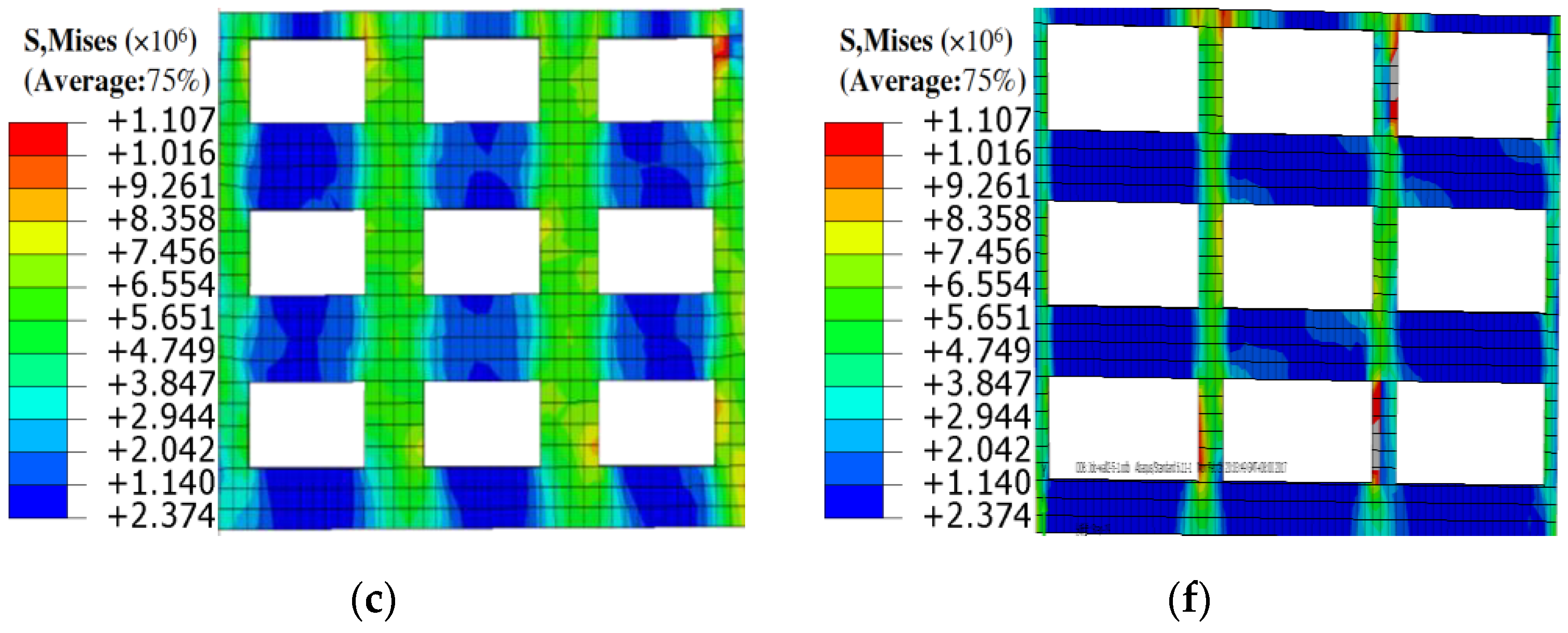
The stress value of each model gradually decreased from first floor to third floor, demonstrating the fact that the damage degree of masonry wall gradually weakened from the bottom floor to the top floor.
(2)
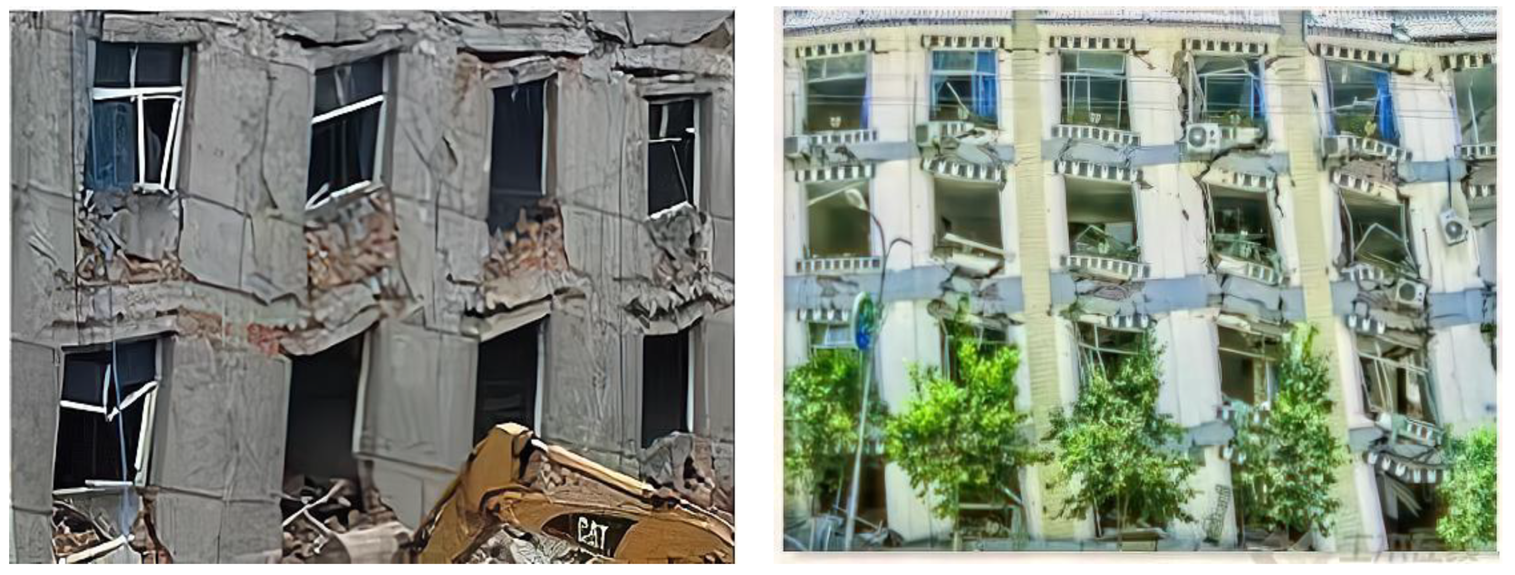
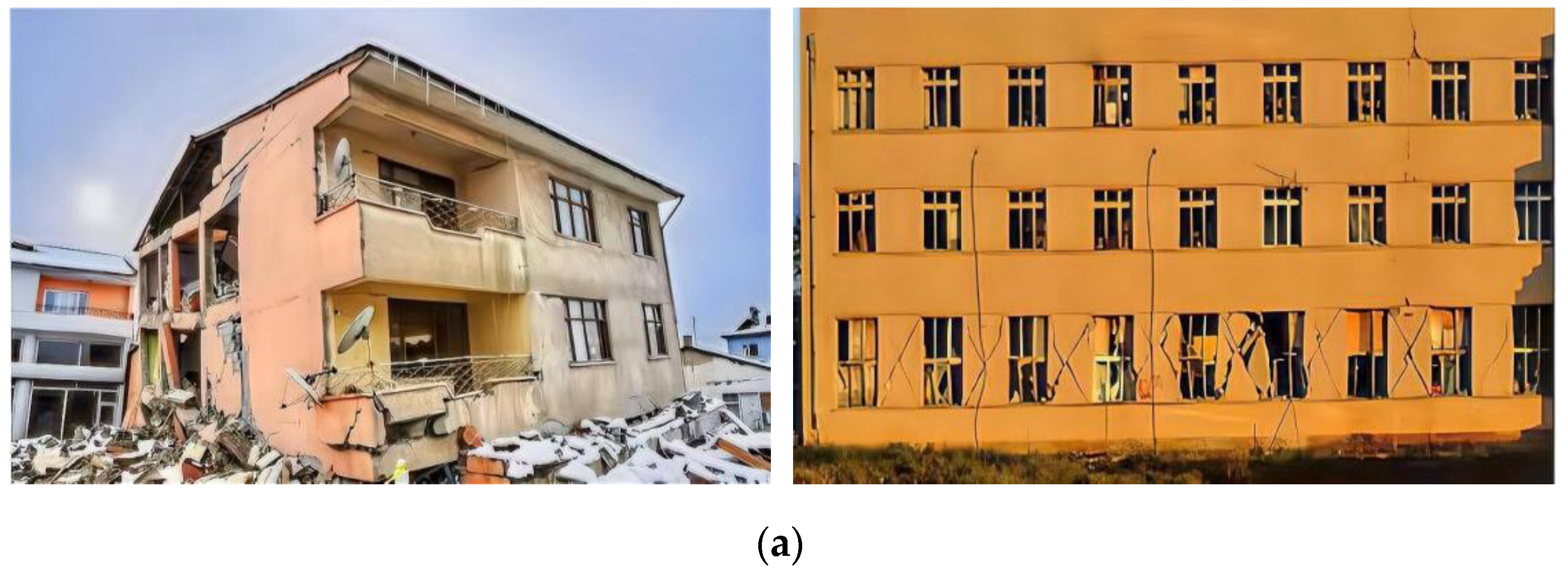
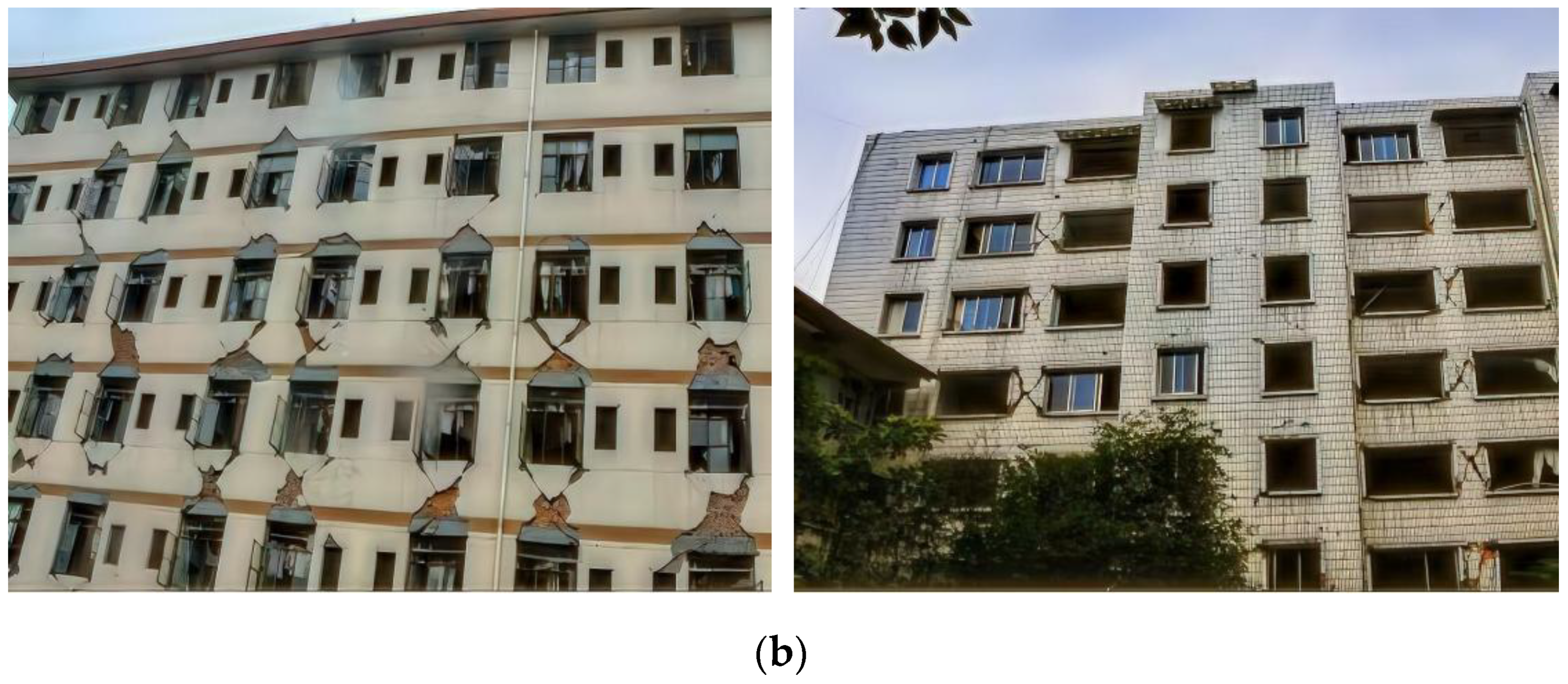
The simulation results exhibited that the cracks and damages of FEMs initially emerged at the edge of the openings, and further elongated and widened along the adjacent parts, which were consistent with the actual earthquake damage phenomenon.
(3)
The failure modes of models with smaller aspect ratio of the pier showed a similar regulation, which was that the failure modes of models transferred from pier failure mode to mixed failure mode and from mixed failure mode to spandrel failure mode with the gradual increase in stiffness ratio of pier to spandrel. However, pier failure mode occurred for all models with a larger aspect ratio of pier only, regardless of whether the stiffness ratio of pier to spandrel increased or decreased.
(4)
Under the identical aspect ratio of pier, the failure modes of the models altered regularly with the increase in vertical load, which transferred from pier failure to mixed failure, and from mixed failure to spandrel failure.
(5)
Considering the failure mechanism of masonry structure “strong pier and weak spandrel” rather than “strong spandrel and weak pier”, the aspect ratio of the pier of masonry structures should not exceed 1.0, and the stiffness ratio of pier to spandrel should be in the range of 1.0–2.0.
(6)
Vertical load has a significant effect on the failure mode of masonry structures. Generally, assuming that the vertical load of each floor is 0.1 MPa, the vertical load that can lead to the “strong pier and weak spandrel” failure mode of n-floors masonry structures shall not be less than (0.1 × n) MPa.
(7)
The numerical simulation in this paper was carried out through the overall model. The anisotropy of brick and mortar was ignored, and the seismic action suffered by masonry buildings was not fully considered. Thus, a separated model should be established to obtain more reasonable simulation results.
(8)
The finite element model used in this paper did not pay attention to the influence of ring beam, structural column and floor, and so on. Therefore, the finite element model considering various influencing factors should be established, so that the stress mechanism and failure mode of masonry buildings can be further discussed and analyzed.

Author Contributions

Conceptualization, P.M. and J.Y.; Methodology, P.M. and J.Y.; Software, P.M. and Y.H.; validation, J.Y.; Formal analysis, P.M. and J.Y.; Investigation, Y.H.; Resources, J.Y.; Data curation, P.M.; Writing—original draft preparation, P.M.; writing—review and editing, P.M.; Visualization, Y.H.; Supervision, J.Y.; Funding acquisition, J.Y. All authors have read and agreed to the published version of the manuscript.

Funding

This research was funded by the Natural Science Foundation of China, grant no. 51978401.

Conflicts of Interest

The authors declare no conflict of interest.

References

  1. Ma, P.; Xin, R.; Yao, J. Assessment of failure mode and seismic performance of damaged masonry structures retrofitted with grout-injected ferrocement overlay reinforcement (GFOR). Constr. Build. Mater. 2021, 305, 124778. [Google Scholar] [CrossRef]
  2. Xin, R.; Ma, P. Experimental investigation on the in-plane seismic performance of damaged masonry walls repaired with grout-injected ferrocement overlay. Constr. Build. Mater. 2021, 282, 122565. [Google Scholar] [CrossRef]
  3. Rossetto, T.; Peiris, N. Observations of damage due to the Kashmir earthquake of October 8, 2005 and study of current seismic provisions for buildings in Pakistan. Bull. Earthq. Eng. 2009, 7, 681–699. [Google Scholar] [CrossRef]
  4. Zhao, B.; Taucer, F.; Rossetto, T. Field investigation on the performance of building structures during the 12 May 2008 Wenchuan earthquake in China. Eng. Struct. 2009, 31, 1707–1723. [Google Scholar] [CrossRef]
  5. Zhou, D.; Lei, Z.; Wang, J. In-plane behavior of seismically damaged masonry walls repaired with external BFRP. Compos. Struct. 2013, 102, 9–19. [Google Scholar] [CrossRef]
  6. Kadam, S.B.; Singh, Y.; Li, B. Strengthening of unreinforced masonry using welded wire mesh and micro-concrete–behaviour under in-plane action. Constr. Build. Mater. 2014, 54, 247–257. [Google Scholar] [CrossRef]
  7. Ismail, N.; Ingham, J.M. In-plane and out-of-plane testing of unreinforced masonry walls strengthened using polymer textile reinforced mortar. Eng. Struct. 2016, 118, 167–177. [Google Scholar] [CrossRef]
  8. Kevin, W.; Dmytro, D.; Ivan, G.; Hossein, D.; Jason, I. Predicted versus experimental out-of-plane force-displacement behaviour of unreinforced masonry walls. Structures 2018, 15, 292–306. [Google Scholar] [CrossRef]
  9. Pradhan, B.; Zizzo, M.; Sarhosis, V.; Cavaleri, L. Out-of-plane behaviour of unreinforced masonry infill walls: Review of the experimental studies and analysis of the influencing parameters. Structures 2021, 33, 4387–4406. [Google Scholar] [CrossRef]
  10. Mojsilović, N. Strength of masonry subjected to in-plane loading: A contribution. Int. J. Solids Struct. 2011, 48, 865–873. [Google Scholar] [CrossRef] [Green Version]
  11. Plevris, V.; Asteris, P.G. Modeling of masonry failure surface under biaxial compressive stress using neural networks. Constr. Build. Mater. 2014, 55, 447–461. [Google Scholar] [CrossRef]
  12. Naraine, K.; Sinha, S. Cyclic behavior of brick masonry under biaxial compression. J. Struct. Eng. 1991, 117, 1336–1355. [Google Scholar] [CrossRef]
  13. Syrmakezis, C.A.; Chronopoulos, M.P.; Sophocleou, A.A. Structural analysis methodology for historical buildings. In Structural Studies of Historical Buildings IV; Computational Mechanics Publications: Lisbon, Portugal, 1995; pp. 373–382. [Google Scholar]
  14. GB/T 50129–2011; Standard for Test Method of Basic Mechanics Properties of Masonry. China Architecture and Building Press: Beijing, China, 2011.
  15. Asteris, P.G. Unified yield surface for the nonlinear analysis of brittle anisotropic materials. Nonlinear Sci. Lett. A 2013, 4, 46–56. [Google Scholar]
  16. Page, A.W. The biaxial compressive strength of brick masonry. Proc. Inst. Civ. Eng. 1981, 71, 893–906. [Google Scholar] [CrossRef]
  17. Samarasinghe, W. The In-Plane Failure of Brickwork. Ph.D. Thesis, University of Edinburgh, Edinburgh, UK, 1980. [Google Scholar]
  18. Dhanasekar, M.; Page, A.; Kleeman, P. The failure of brick masonry under biaxial stresses. Ice Proc. 1985, 79, 295–313. [Google Scholar] [CrossRef]
  19. Tassios, T.P.; Vachliotis, C. Failure of masonry under heterosemous biaxial stresses. In Structural Conservation of Stone Masonry; International Centre for the Study of the Preservation and the Restoration of Cultural Property: Rome, Italy, 1990; pp. 273–282. [Google Scholar]
  20. Liu, L.P.; Tang, D.X.; Tian, Y.B. Experimental study of anisotropic strength characteristics of grouted concrete block masonry. J. Build. Struct. 2005, 26, 91–95. [Google Scholar]
  21. Liang, J.G.; Fang, L. Yield criterion and calculation of shear strength for brick masonry walls. Chin. J. Civ. Eng. 2010, 43, 43–46. [Google Scholar]
  22. Xin, R.; Yao, J.; Zhao, Y. Experimental research on masonry mechanics and failure under biaxial compression. Struct. Eng. Mech. 2017, 61, 167–175. [Google Scholar] [CrossRef]
  23. Ma, P.F. Experimental Study on Seismic Behavior of Reinforced Masonry Structure Based on Spandrel Failure Mode. Master’s Thesis, Xi’an University of Architecture and Technology, Xi’an, China, 2019. [Google Scholar]
  24. EN 1998-1; Eurocode 8–Design of Structures for Earthquake Resistance—Part 1: General Rules, Seismic Actions and Rules for Buildings. European Standard NFEN; European Committee for Standardization: Brussels, Belgium, 1998.
  25. FEMA 356; Prestandard for the Seismic Rehabilitation of Existing Structures. FEMA: Washington, DC, USA, 2000.
  26. Lagomarsino, S.; Penna, A.; Galasco, A.; Cattari, S. TREMURI program: An equivalent frame model for the nonlinear seismic analysis of masonry buildings. Eng. Struct. 2013, 56, 1787–1799. [Google Scholar] [CrossRef]
  27. D’Altri, A.M.; Sarhosis, V.; Milani, G.; Rots, J.; Cattari, S.; Lagomarsino, S.; Sacco, E.; Tralli, A.; Castellazzi, G.; de Miranda, S. Modeling strategies for the computational analysis of unreinforced masonry structures: Review and classification. Arch. Comput. Methods Eng. 2019, 27, 1153–1185. [Google Scholar] [CrossRef]
  28. Rinaldin, G.; Amadio, C.; Gattesco, N. Review of experimental cyclic tests on unreinforced and strengthened masonry spandrels and numerical modelling of their cyclic behaviour. Eng. Struct. 2017, 132, 609–623. [Google Scholar] [CrossRef]
  29. Abrams, D.P. Seismic response patterns for URM buildings. J. Mas Soc. 2000, 18, 71–78. [Google Scholar]
  30. GB 50203–2011; Code for Design of Masonry Structures. China Architecture and Building Press: Beijing, China, 2011.
  31. Ewing, R.D.; Kariotis, J.C.; Mustapha, A. A computer program for the nonlinear, dynamic, analysis of lumped parameter models. In US–Japan Coordinated Program for Masonry Building Research; National Technical Information Service: Springfield, VA, USA, 1988. [Google Scholar]
  32. Parisi, F.; Lignola, G.P.; Augenti, N.; Prota, A.; Manfredi, G. Rocking response assessment of in-plane laterally-loaded masonry walls with openings. Eng. Struct. 2013, 56, 1234–1248. [Google Scholar] [CrossRef]
  33. Gattesco, N.; Clemente, I.; Macorini, L. Experimental investigation on the behaviour of spandrels in ancient masonry buildings. In Proceedings of the 14th World Conference on Earthquake Engineering, Beijing, China, 12–17 October 2008. [Google Scholar]
  34. Parisi, F.; Augenti, N.; Prota, A. Implications of the spandrel type on the lateral behavior of unreinforced masonry walls. Earthq. Eng. Struct. Dyn. 2014, 43, 1867–1887. [Google Scholar] [CrossRef]
  35. Mahdavi, N.; Ahmadi, H.R.; Mahdavi, H. A comparative study on conventional push-over analysis method and incremental dynamic analysis (IDA) approach. Sci. Res. Essays 2012, 7, 751–773. [Google Scholar]
  36. Ahmadi, H.R.; Namdari, N.; Cao, M. Seismic investigation of pushover methods for concrete piers of curved bridges in plan. Comput. Concr. 2019, 23, 1–10. [Google Scholar]
  37. Ahmadi, H.R.; Mahdavi, N.; Bayat, M. Applying adaptive pushover analysis to estimate incremental dynamic analysis curve. J. Earthq. Tsunami 2020, 14, 2050016. [Google Scholar] [CrossRef]
  38. Knox, C.L.; Dizhur, D.; Ingham, J.M. Experimental cyclic testing of URM pier-spandrel substructures. J. Struct. Eng. 2016, 143, 04016177. [Google Scholar] [CrossRef]
  39. Yang, W.Z. Constitutive relationship model for masonry materials in compression. Build. Struct. 2008, 10, 80–82. [Google Scholar]
  40. Yan, F. Study on the Whole Mechanics of Wall Structure of Masonry Structure. Master’s Thesis, Xi’an University of Architecture and Technology, Xi’an, China, 2017. [Google Scholar]
  41. GB/T 2542–2012; Test Method for Wall Bricks. China Architecture and Building Press: Beijing, China, 2012.
  42. GB/T 25181–2019; Ready-Mixed Mortar. China Architecture and Building Press: Beijing, China, 2019.
  43. Gattesco, N.; Amadio, C.; Bedon, C. Experimental and numerical study on the shear behavior of stone masonry walls strengthened with GFRP reinforced mortar coating and steel-cord reinforced repointing. Eng. Struct. 2015, 90, 143–157. [Google Scholar] [CrossRef] [Green Version]
  44. Xia, Y.X. Study on Seismic Damage Mechanism of Masonry Spandrel Walls. Master’s Thesis, Institute of Engineering Mechanics, China Seismological Bureau, Harbin, China, 2011. [Google Scholar]
  45. GB 50009–2012; Load Code for the Design of Building Structures. China Architecture and Building Press: Beijing, China, 2012.
  46. Hadzima-Nyarko, M.; Čolak, S.; Bulajić, B.; Ademović, N. Assessment of selected models for FRP-retrofitted URM walls under in-plane loads. Buildings 2021, 11, 559. [Google Scholar] [CrossRef]
  47. Cavaleri, L.; Di Trapani, F.; Asteris, P. Infilled frames and equivalent struts: An approach considering the effects of openings and vertical loads. J. Struct. Infrastruct. Eng. 2015, 12, 551–566. [Google Scholar]
Figure 1. Finite element model: (a) loads and boundaries, (b) masonry-top-loading beam and masonry-concrete-bottom beam surfaces for the introduction of tie constraints.
Buildings 12 00183 g001
Figure 2. The testing of mechanical properties of brick (a), masonry (b) and mortar (c,d).
Buildings 12 00183 g002
Figure 3. Damaged precast floor slab and spandrel in Ya’an, Sichuan, China.
Buildings 12 00183 g003
Figure 4. Typical damaged masonry buildings in Ya’an, Sichuan, China: (a) masonry buildings of 2–3 floors; (b) masonry buildings of 5–6 floors.
Buildings 12 00183 g004aBuildings 12 00183 g004b
Figure 5. Comparison of simulation results of partial models: (a) M2-1 (η = 1.0, ρ = 0.5); (b) M2-4 (η = 1.0, ρ = 1.25); (c) M2-7 (η = 1.0, ρ = 2.0); (d) M3-1 (η = 1.8, ρ = 0.5); (e) M3-4 (η = 1.8, ρ = 1.25); (f) M3-7 (η = 1.8, ρ = 2.0).
Buildings 12 00183 g005aBuildings 12 00183 g005b
Table 1. Relevant data in reference [23] (MPa).
Loading DisplacementLocation of
Data Extraction
σxσyτxy
4 mmspandrel (2nd)−0.142453−0.0303030.092791
pier (1st)−0.024440−0.3184600.091702
Table 2. Partial design parameters of M1, M2 and M3 (unit: mm).
ModelWidth × Height of PierWidth × Height of Spandrelηρ#
M1-11800 × 1500435 × 15000.80.5
M2-11500 × 1500750 × 15001.00.5
M3-11000 × 18001550 × 12001.80.5
#η represents aspect ratio of pier, ρ represents stiffness ratio of pier to spandrel.
Table 3. Comparison of failure modes of all models (σ = 0.3 MPa).
Parametersρ = 0.5ρ = 0.75ρ = 1.0ρ = 1.25ρ = 1.5ρ = 1.75ρ = 2.0Models
η = 0.8PPMMSSS *M1-1~M1-7
η = 1.0PPMMMSSM2-1~M2-7
η = 1.8PPPPPPPM3-1~M3-7
* σ represents vertical load; η represents aspect ratio of pier, ρ represents stiffness ratio of pier to spandrel, P represents pier failure mode; M represents mixed failure mode; S represents spandrel failure mode.
Table 4. Comparison of failure modes of all models (η =1.0).
Modelsρ = 0.5ρ = 0.75ρ = 1.0ρ = 1.25ρ = 1.5ρ = 1.75ρ = 2.0
σ = 0.3 MPaPPMMMSS
σ = 0.6 MPaMMMSSSS
Publisher’s Note: MDPI stays neutral with regard to jurisdictional claims in published maps and institutional affiliations.

