Article

Investigations on the Response of Novel Layered Geopolymer Fibrous Concrete to Drop Weight Impact

by
Sundaravadivelu Karthik
*,
Kaliyaperumal Saravana Raja Mohan
and
Gunasekaran Murali
School of Civil Engineering, SASTRA Deemed University, Thanjavur 613401, India
*
Author to whom correspondence should be addressed.
Buildings 2022, 12(2), 100; https://doi.org/10.3390/buildings12020100
Submission received: 28 December 2021 / Revised: 12 January 2022 / Accepted: 13 January 2022 / Published: 21 January 2022

Abstract

:
In recent years, geopolymer concrete (GC) has become more popular in construction because of its multiple benefits, such as eco-friendliness, high temperature resistance and resistance to chemical attack in harsh environments. However, GC has limited deformation capability and tensile strength compared to ordinary concrete. Geopolymer fibrous concrete (GFC) exhibits high mechanical properties, such as compressive strength and impact strength. This study aimed to develop a novel composite comprising GFC at the tension zone and GC at the compression zone, and vice versa, are these composites were examined. The impact resistance of two-layered GC-GFC with various ratios (25–75, 50–50, 75–25%) was examined. In addition, a single layer specimen comprising GC and GFC was fabricated and tested as the reference specimen. Twenty-nine mixtures were developed and divided into four series. Four different types of fibre were used in this study; short polypropylene fibre, long polypropylene fibre, short steel fibre and long steel fibre. The ACI committee 544 drop weight test was used to evaluate the impact strength of specimens. Results indicated that the impact strength of GFC was significantly improved in long steel fibre-based specimens. In addition, two-layered specimens comprising different fibres—short polypropylene, long polypropylene, short steel and long steel—exhibited a positive influence on impact strength. Compared to a single-layer specimen, inferior impact strength was recorded in the two-layered specimen.

1. Introduction

Geopolymer concrete (GC) has become more established in building technologies as a greener option for ordinary Portland cement in recent years, to create renewable and eco-friendly composites. Production of ordinary Portland cement generally results in an increase of around 900–1000 kg of CO2 in the environment for every 1000 kg of cement produced [1,2,3,4]. Using ordinary Portland cement as a binder in construction poses a major environmental risk, and hence it must be reduced or eliminated. Several pozzolanic materials with high silicon content and alumina, such as ground granulated blast furnace slag (GGBFS), metakaolin (MK) and fly ash (FA), have recently emerged as potential new building materials, collectively known as GC [5]. Polycondensation of silicon and alumina precursors with an alkaline solution is required to generate a chain structure, which is required for geopolymer binders to function [6]. As a result, geopolymer binders are now a cutting-edge material capable of enhancing concrete performance in terms of creep, shrinkage, acid resistance, fire resistance and compressive strength [7]. GC has been demonstrated to have mechanical properties, strength and stiffness qualities that are equivalent to those of traditional ordinary Portland cement-based concrete [8]. As a result, GC has been progressively employed in the building of structural components, such as slabs, walls, columns and beams, during the past two decades [9,10,11]. Despite inheriting higher plastic/drying shrinkage and brittleness, geopolymers enriched in aluminosilicates show significantly reduced tensile and flexural strengths, and limited deformation capability when subjected to moderate mechanical load or shrinkage forces. As a result, they experience sudden failure due to the proliferation and coalescence of minute cracks developed both in the pre-hardened and the hardened states [12,13].
The inclusion of randomly dispersed fibres as internal reinforcement is a typical method for improving concrete’s post-peak performance. Fibres have been demonstrated to be capable of delivering the required mechanical properties in a timely way [14]. Fibres act as a bridge across cracks, narrowing their breadth and decreasing their inclination to spread, hence increasing strain softening. This changes the material’s failure mode from brittle to ductile, which is a more desirable outcome. Studies reported that the inclusion of fibres in geopolymers has also been shown to improve their fracture toughness and splitting tensile strength [15,16], because the integration of fibre geopolymers can absorb more energy under external tensile load [17]. A greater level of energy is needed to draw fibre out and progress crack propagation in composites during fibre bridging [18]. This energy need is mostly determined by the fibre orientation, fibre count, fibre stiffness and bondage between fibre and binder. However, fibre content over a particular threshold has been observed to increase the lack of uniformity with the establishment of fibre concentration spots in the matrix. Entanglement of fibres results in porosity and a weaker composite due to fresh matrix flow being impeded. Steel fibre added to a geopolymer composite increased its strength by 54%, according to Sukontasukkul et al. [19]. Polypropylene fibres were shown to be the most effective in creating lightweight geopolymer concrete with a low density and high compressive strength, according to Mohseni et al. [20]. Precursor-based geopolymer synthesis using Nano-Al2O3 and rice husk ash together with lightweight aggregates resulted in concrete with a slightly enhanced compressive strength of 1.4% and 2.3%, respectively. Shaikh [21] reported that the compressive strength was reduced, while the insertion of fibres resulted in significant improvements in the splitting tensile and flexural strengths. Steel fibres with high modulus are most likely responsible for their enhanced flexural strength. Ganesan et al. [22] reported steel fibre has been shown to improve splitting tensile strength by 23% for a 0.25 % dosage and up to 62% for a 1% dosage, according to the research. Patil et al. [23] studied the polypropylene-based GFC with solution of sodium hydroxide/sodium silicate = 2.5 and alkaline liquids/fly ash = 5. Findings indicated that adding 1.5% dosage of 20 mm polypropylene fibre to GC improved its flexural strength, split tensile strength and compressive strength by 19%, 12% and 8%, respectively.
Although several studies have been undertaken on the mechanical and durability of GFC, the impact performance of GFC is unexplored and only a limited number of studies is available. Li et al. [24] examined the impact behaviours of basalt fibre-based GFC using the split Hopkinson pressure bar test. Findings indicated that the basalt fibre addition showed a considerable increase in deformation performance and energy absorption, but exhibited less improvement in dynamic compressive strength. The orientation of steel fibres in GFC plays a crucial role in defining its mechanical properties under impact stress, according to Jacob et al. [25]. Puertas et al. [26] compared the impact resistance of acrylic and polypropylene fibre-based geopolymer mortar. Results revealed that the polypropylene fibres outperformed acrylic fibres in terms of impact resistance improvement. Ulzurrun et al. [27] demonstrated adding a 1% dosage of steel fibre changes the mode of failure from shear to flexure, results in a higher impact performance. Asrani et al. [28] investigated the impact behaviour of GFC against drop weight impact. The mono and hybrid glass, polypropylene and steel fibres were used to produce the GFC mixes. Results indicated that the inclusion of 1% steel, 0.3% polypropylene and 0.3% glass fibre hybridization showed an increase in maximum impact strength for first crack and failure by 7.9 and 10.4 times respectively, compared to non-fibrous GC. An improvement in impact ductility was found in the range of 8.6% to 196.1% when mono and hybrid fibres were used in the GC.
Nikbakht et al. [1] investigated the structural behaviour of hybrid beams made up of two separate layers of GC and high-performance concrete (HPC) with various ratios (50–50%, 75–25%). Additionally, the shear strength, fracture patterns, failure modes, ductility and energy absorption of beams with and without shear reinforcement were examined. The findings reveal that hybrid composite beams without shear reinforcement have lower ultimate strength than full-depth GC and HPC beams, due to substantial debonding between the GPC and HPC layers. Cao et al. [29] investigated the impact resistance of ultra-high performance concrete beams that were constructed of single and double layers of reinforced concrete. The single-layered beam had a thickness of 100 mm. The top and bottom layers of the double-layered beam had thicknesses of 40 and 60 mm, respectively. In the top and bottom layers, several fibre schemes (mono and hybrid) were used. Results indicated that a 28% increase in absorbed impact energy may be achieved by the double-layered beam, compared to the similar single-layered beam with the same fibre quantity. Nandhu prasad et al. [30] investigated the projectile impact performance of three-layered functionally graded preplaced aggregate fibrous concrete. Steel and polypropylene fibres were used in three layers with different dosages and hybrid combinations. Findings revealed a greater reduction in the damaged area with impact blows for three-layered concrete than for two-layer concrete. A greater number of fibres were provided in the top layer, resulting in a significant reduction in penetration depth and damage area.
Despite the research noted above, the research on the impact response of GFC is severely lacking in information, particularly concerning the use of various types of fibres, because GFC studies are few in number. Although GFC has been used in the construction sector, it has not yet gained widespread acceptance, and it is still viewed as a new technology. In this study, a novel layered GFC was proposed to attain both high impact resistance and sustainability. Moreover, the impact resistance of GFC is explored with four different types of fibres. In addition, the impacts of a variety of GC-to-GFC ratios in hybrid composites were explored. The experimental findings were compared to those obtained from full-depth GC and GFC specimens. The parameters examined were the number of hits causing first crack and failure, the ductility index and the mode of failure. Layered GFC has the potential to be used in a broad range of impact-resistant applications in critical structures; for example, vehicle accidents on transportation structures, flooring, rock shelters, long-span bridges, structures exposed to cluster bombs, and airfield pavements. Layered GFC is simple to manufacture because the traditional casting procedure is involved layer-wise in GC or GFC.

2. Materials and Methods

2.1. Raw Materials

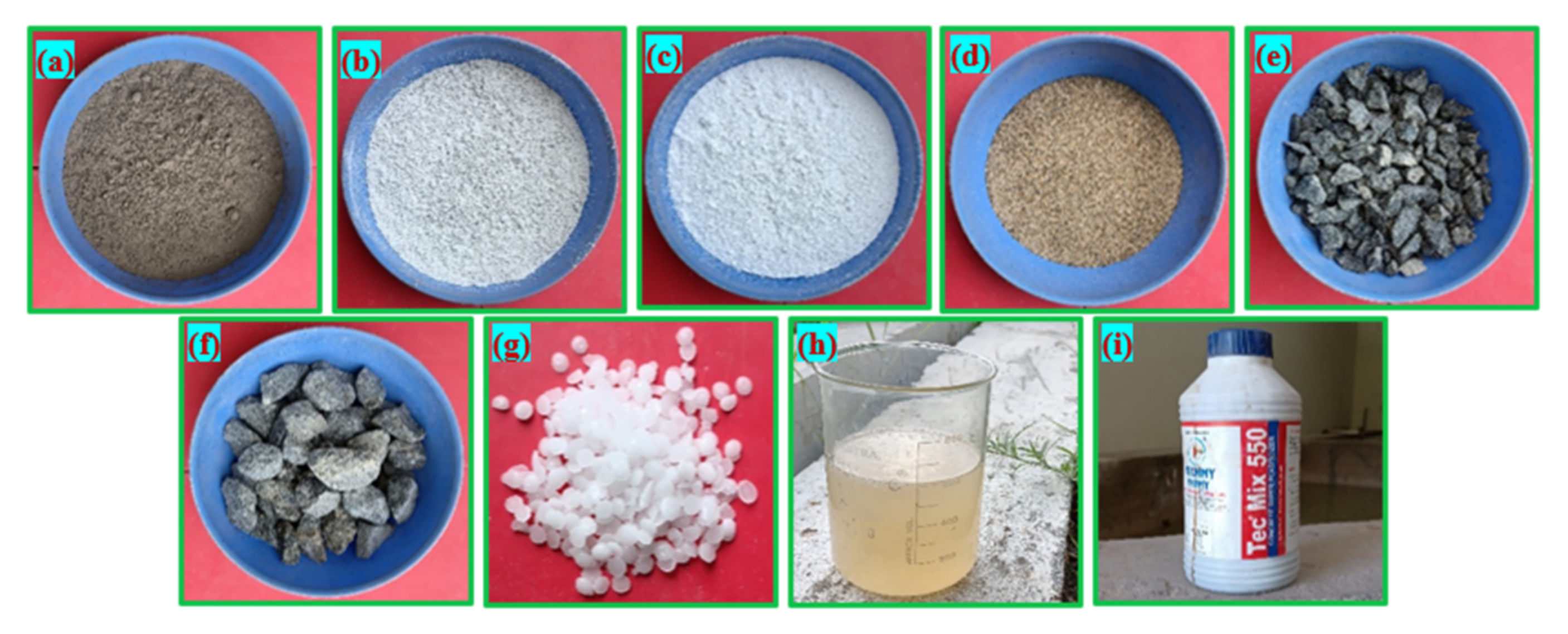
  • For the binder, Class F fly ash (FA) in compliance with ASTM C618-08 standards [31], provided by Neyveli Lignite Corporation, was used. GC was made using a mixture of silica fume (SF), GGBFS and FA, and the fabricated specimens were cured at room temperature throughout the process. GGBFS and CaO concentrations have been shown to speed up polymerization in previous research [32]. A dense matrix may also be formed by silica fumes that have a lower particle size by reacting more quickly with an alkaline solution [32]. The alkali solutions, GGBFS and SF were supplied by Astra Chemicals Chennai. Table 1 demonstrates the chemical properties of GGBFS, FS and SF. Figure 1 depicts the raw materials used in this study.
  • River sand with a specific gravity of 2.65 and a fineness modulus of 2.41 was used as fine aggregate in accordance with the standards of IS 383 [33]. The particle size of the fine aggregate did not exceed 2.36 mm.
  • Crushed granite gravel having a size of 12.5 was utilized as coarse aggregate in accordance with IS 383 [33]. The bulk density, specific gravity and water absorption of coarse aggregate were 1700 kg/m3, 2.69 and 0.56%, respectively.
  • A superplasticizer (Tech Mix 550) was used with a dosage of 1.5% by cement weight to produce a workable GC.
  • The pozzolanic binders were activated using a mixture of NaOH and Na2SiO3. When preparing an alkaline solution, pellets of sodium hydroxide were liquified in distilled water to the required molar content, and then sodium silicate was added to make an alkaline solution. One day before casting the specimens, the solution was made and stored. A Na2SiO3/NaOH ratio = 1.5 and molar content of 12 were employed in this study. These ratios were determined based on the several trials of the compressive strength test.
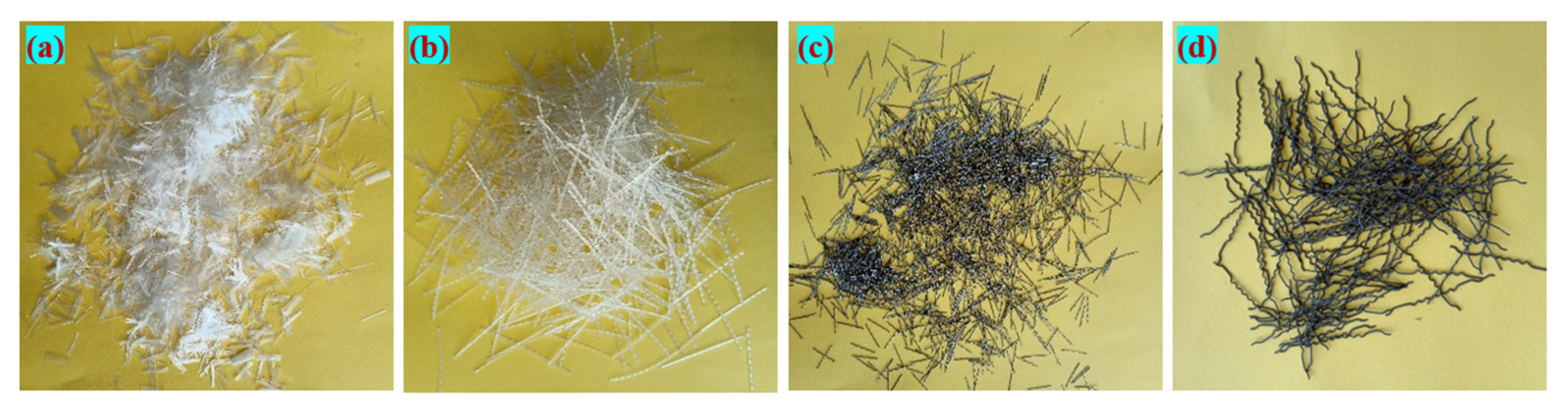
  • Four different types of fibres were used: short polypropylene fibre (SPF), long polypropylene fibre (LPF), short steel fibre (SSF) and long steel fibre (LSF). The details of the fibres and their properties are demonstrated in Table 2. The appearance of the four different fibres is shown in Figure 2. The dosage of fibres was taken or calculated based on the volume of the concrete.

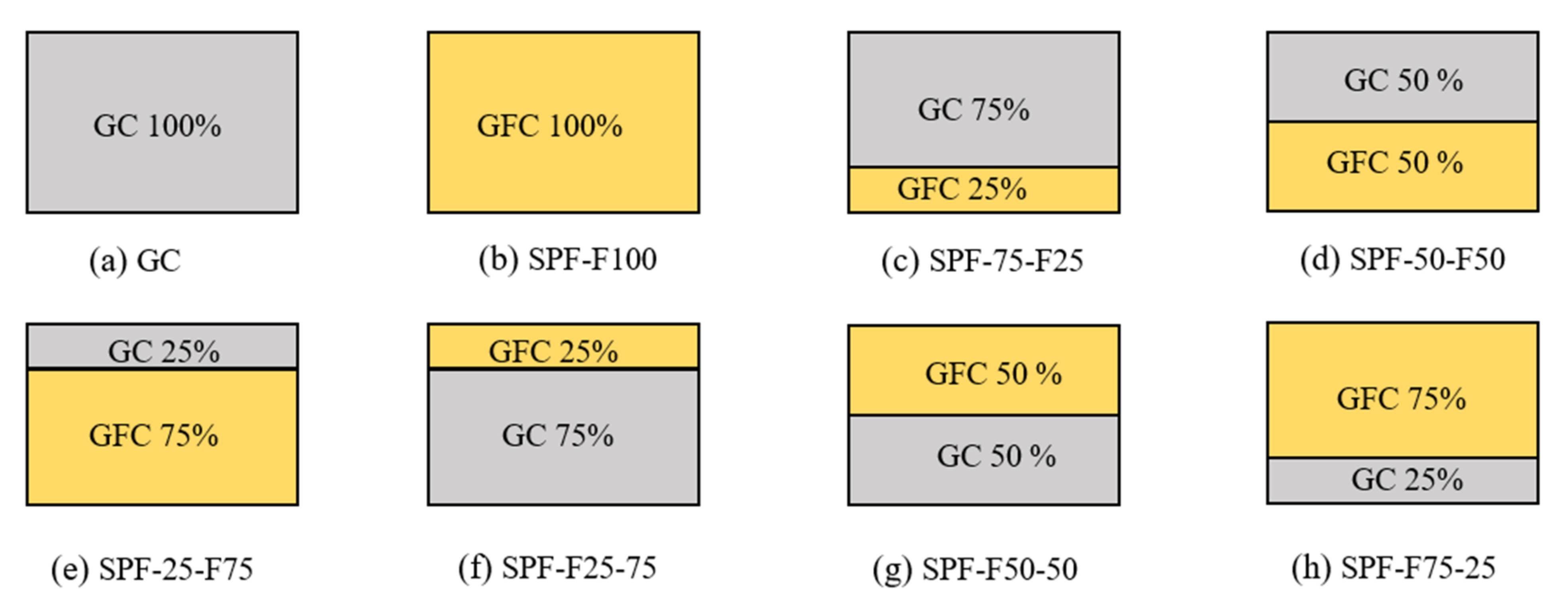
2.2. Mixing Combination and Specimen Preparation

Table 3 shows the mixing combination of the base material for the binder (SF, FA and GGBFS), fine and coarse aggregates, and the type of fibres employed in this study. A compressive strength of more than 30 MPa was achieved via several tests with these materials and amounts selected for use. To begin the GFC casting process, dry components such as FA, GGBFS and SF were combined and mixed for 1 min; next, the fine aggregate was added to the mixture and mixed for 2 min. Then, coarse aggregates and fibres were added and the mixture was allowed to mix until the fibres were uniformly distributed. The dry mixture of the GFC is shown in Figure 3a. Alkaline solutions and superplasticizers were then added to a dry mixture and the mixing process was continued for 3 min to obtain a homogenous mixture. The wet mixture of the GFC is shown in Figure 3b. All specimens were cast immediately (within 5 min) to ensure the uniform compaction and density of concrete. After demoulding, specimens were allowed to cure at room temperature (24 °C and 20% relative humidity) for 28 days before the testing process was initiated. The appearance of the cast specimens is shown in Figure 3c, and the sample specimens after demoulding and before testing are shown in Figure 3d.
Twenty-nine mixtures were prepared and divided into four series. The first mixture was designated as GC comprising no fibres and considered as a reference specimen. The next seven mixtures belonged to series one, and all specimens from this series comprised SPF at a dosage of 1.5 %. The first mixture from series one was designated as SPF-F100, which indicated a single-layered specimen. The second, third and fourth mixtures were designated as SPF-75-F25, SPF-50-F50 and SPF-25-F75, respectively. Two-layered concrete was proposed at different depths of the top and bottom layer with GC and GFC. The first term denotes a type of fibre used, the second term denotes the top layer depth in terms of percentage of the full depth, and the third term denotes the bottom layer depth in terms of percentage; “F” denotes the fibrous mixture. Mixtures five, six and seven were the same as mixtures two, three and four, but the top and bottom layer were reversed (GFC mixture at the top layer and GC at the bottom layer). The second, third and fourth series specimens were prepared with LPF, SSF and LSF, respectively. The two-layered scheme used for the first series is the same as that for the other three series except for the type of fibre used. Figure 4 illustrates the details of the layered specimens with different depths of the GC-GFC scheme.

2.3. Drop Weight Impact Testing Device

All specimens were subjected to an impact test to evaluate their impact strength according to ACI Committee 544-2R guidelines [34]. The simplified drop-weight impact test is a simple testing technique and method because it does not need measurement of the vibration, time history or displacement. The test involved raising and dropping a steel hammer having a weight of 4.45 kg, from a height of 457 mm to the top surface of a steel ball placed on top of the specimen. Figure 5 shows the drop-weight impact testing device employed in this study. The impact numbers that caused the specimen’s first visible cracking (A1) and failure (A2) were noted and inspected visually. The crack was defined as a failure when it reached the specimen at the bottom and split it into two pieces.

3. Discussion of Results

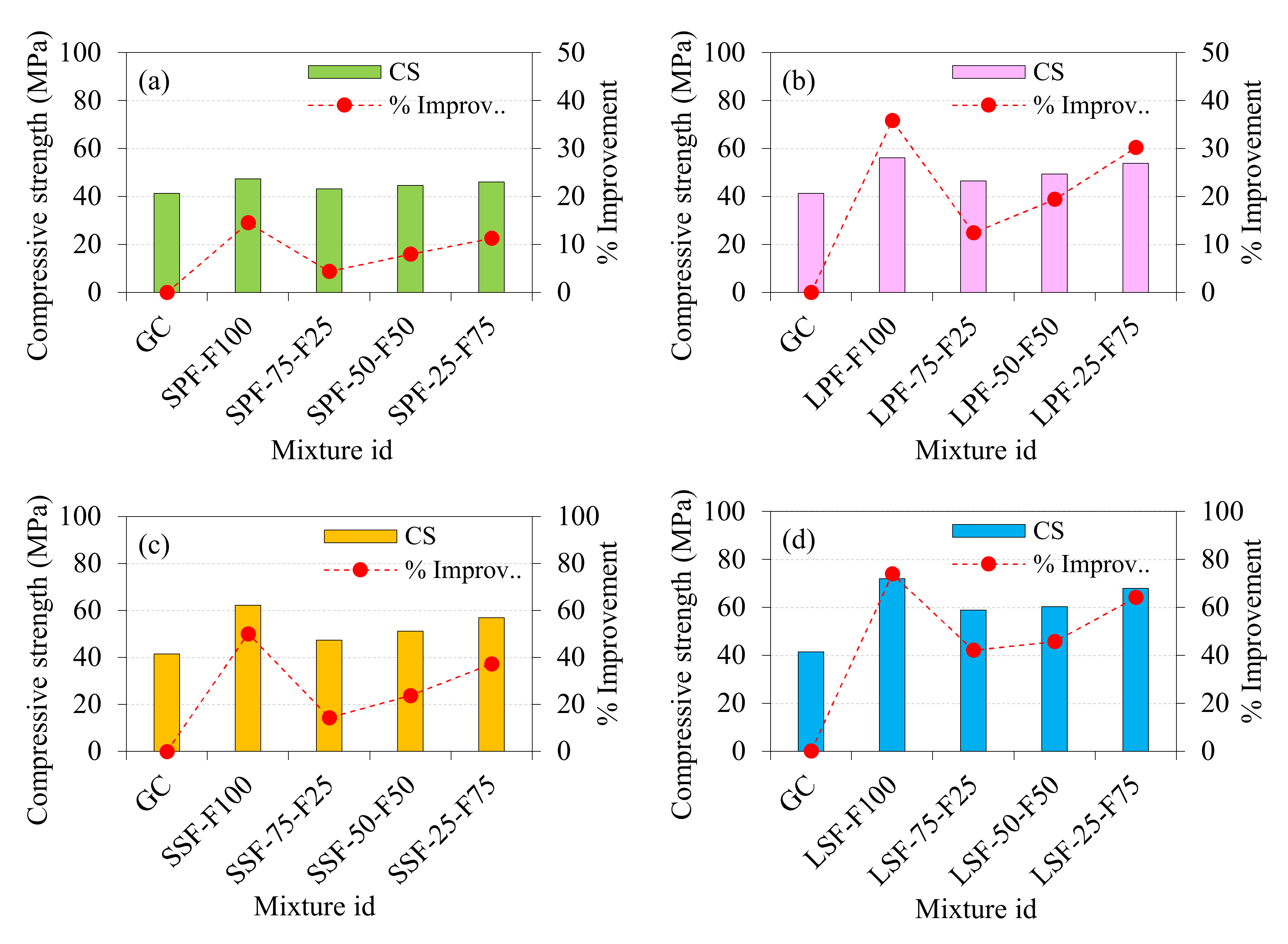
3.1. Compressive Strength of GFC

According to ASTM C39 [35], the compressive strength was evaluated using 100 mm cubes. The mean value of three cubes is used for the discussions. The compressive strength was investigated to evaluate the effect of four different fibres and two layers of GC-GFC with various ratios on the compressive behaviour of GFC. The results are illustrated in Figure 6. As shown, the lowest compressive strength (41.34 MPa) was recorded in the GC specimen. The primary cause for GC’s brittle behaviour is a lack of fibre bridging action. Figure 6a depicts the influence of SPF on compressive strength. Introducing specimen SPF-75-F25 having a 25% depth of GFC at the bottom layer and the remaining 75% depth of GC at the top layer exhibited a 4.4% improvement in compressive strength, compared to the reference specimen (GC). Similarly, a specimen (SPF-50-F50) with 50% depth of GFC at the bottom and a 50% depth of GC at the top layer resulted in a 7.5% improvement. The second-highest improvement in strength was exhibited by the SPF-25-F75 specimen, of 11.2% compared to GC. The single-layer specimen (SPF-F100) exhibited a significant improvement in compressive strength, of 14.5%. It is clear from the above discussions that increasing the depth of GFC from 25 to 100% results in a significant improvement in compressive strength. A significant contribution to the improved compressive performance of GFC is due to the bridging action of SPF, which results in the formation of a high-strength core in the GFC specimen against compression stress, which prevents enlargement in the lateral direction [36]. When a specimen is compressed, there is an expansion in the lateral direction that is concentrated at the centre of the specimen’s height. The SPF bridging action enhances the concrete matrix tensile strength and the cohesiveness between the aggregate and concrete paste. This reduced expansion in the lateral direction results in an improvement in the compressive performance of GFC.
Figure 6b depicts the influence of LPF on compressive strength. Figure 6d clearly shows the large improvement in the compressive strength of LPF-75-F25, LPF-50-F50 and LPF-25-F75 specimens, which were 12.41, 19.40 and 30.19%, respectively, compared to GC. However, the specimens consisting of a 100% depth of the GFC mixture resulted in a 35.82% improvement in strength. Increasing the depth of fibrous mixture (GFC) from 25 to 100% led to an excellent enhancement in compressive strength ranging, from 12.41 to 35.82%. This phenomenon is caused by the fibre bridging effect of LPF, which results in a considerable increase in the compressive strength of the GFC. Bridge effect activation occurs during crack initiation, causing the matrix to partially transmit loads to fibres. Compressive strength then increases as the load is transferred between fibres and the interfacing material. Compressive strength may be further improved by increasing the content of fibres, which can significantly increase the overall contact area between the fibres and matrix [37]. The influence of SSF on compressive strength is shown in Figure 6c. The SSF-75-F25, SSF-50-F50 and SSF-25-F75 specimens exhibited an significant improvement in compressive strength, by 14.30, 23.73 and 37.35%, respectively, compared to GC. The compressive strength increased with the increased depth of FGC layers (25–75%). However, the best contribution was recorded from the SSF-F100 specimen, which exhibited a 50.15% strength improvement. The phenomenon of strength improvement is due to SSF, which plays a significant role in boosting the energy absorption capacity in the cracking zone and establishing a nonstop crack tip due to the bridging action of multiplying cracks, consequently serving as a crack arrester [38].
The contribution of LSF in increasing compressive strength was remarkable compared to SPF, LPF and SSF. An excellent increase in compressive strength in LSF-based GFC is shown in Figure 6d. Compared to GC, the compressive strength of LSF-75-F25 was improved by about 42.11%. However, this strength was further improved in the LSF-50-F50 specimen, by about 45.77%. The SSF-25-F75 specimen also exhibited a significant improvement in strength, by 64.15%. The above discussion indicates that increasing the depth of the fibrous layer resulted in increasing compressive strength. The highest compressive strength was exhibited by the LSF-F100 specimen and the improvement was 73.88%, which is a remarkable finding. The reason for this behaviour is that longer fibres were better able to control the formation and crack propagation [39]. Additionally, long fibres (LSF) are superior at resisting macro-cracks that can broadly disperse the crack pattern. The potential of equally dispersed LSFs is usually the primary cause of an inherent improvement in compressive strength, reducing stress concentration and promoting uniform stress in concrete [40]. As a result, bridging occurs when cracks change direction, and strengthening results in a delay in the rate of crack propagation [41]. In summary, the compressive strength was increased with the increase in the depth of the fibre layer for all four types of fibre. Single-layer specimens having a depth of fibres of 100% exhibited a higher compressive strength than the two-layered specimens. Moreover, the performance of LSF showed an excellent contribution to strength enhancement, followed by the SSF, LPF and SPF fibres.

3.2. Impact Test Results

The number of hits causing the first cracking (A1) and failure (A2) of all twenty mixtures are summarized in Table 4. The mean value of three specimens is used for the discussions.

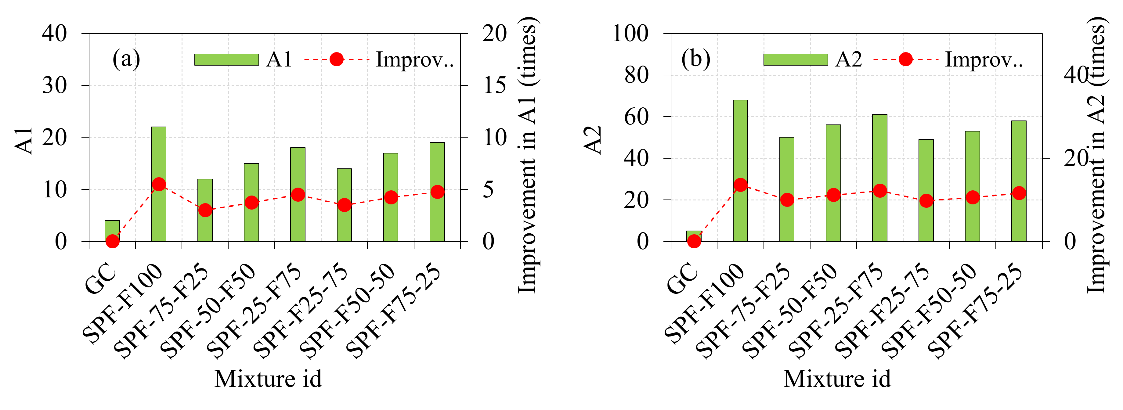
3.2.1. Influence of SPF on the Impact Strength of GFC

The addition of SPF in two-layered GFC positively influenced the impact strength of the composite. Concerning the results attained in two-layered GFC, it is evident from Figure 7 that the greater depth of fibrous layers enhanced the A1 and A2 values of FGC specimens. The recorded A1 and A2 values for the GC specimen were 4 and 5, respectively. This indicates the inferior post crack resistance leading to brittle failure. Compared to the GC specimen, the impact strength enhancement in the first series specimens is discussed as follows:
  • The recorded A1 and A2 values for the SPF-F100 specimens were 22 and 68, respectively, and these values were 5.5 and 13.6 times higher than that of GC.
  • For the SPF-75-F25 specimen, the recorded values were 12 and 50 for A1 and A2, respectively. However, 3.0- and 11.2-fold improvements were recorded for A1 and A2, respectively.
  • The A1 and A2 values reported for the SPF-50-F50 specimens were 15 and 56, respectively, which were 3.75 and 11.2 times higher than the GC values.
  • The A1 and A2 values for the SPF-25-F75 specimens were recorded as 18 and 61, respectively, and these values were 4.5 and 12.2 times higher than those for the GC specimens, respectively.
  • SPF-F25-75 specimens had A1 and A2 values of 14 and 49, which were 3.5 and 9.8 times higher than those of GC.
  • The recorded values for SPF-F50-50 specimens were 17 and 53 for A1 and A2, respectively. However, improvements of 4.25 and 10.6 times were seen for A1 and A2, respectively.
  • For the SPF-F75-25 specimen, the values associated with A1 and A2 were 19 and 58, respectively, as recorded. A1 and A2 had the greatest gains, with increases of 4.75 and 11.6 times, respectively.
SPF added to FGC specimens increased their A1 and A2 values, as we can observe from the results of the research above. The increase in the depth of the second layer comprising SPF resulted in increasing A1 and A2 values. The addition, the fibre and distribution in concrete were the most common causes of a rise in A1 and A2 values. Micro-crack formation is prevented by uniformly dispersed fibres, and better stress homogeneity in concrete is made possible by spreading out the tension across a larger region [42]. Fibre bridging action, which delays crack propagation and lowers the width of the crack, may be accounted for by changing the crack’s direction. Cracks first appeared at the micron size, but as time progressed, they began to appear at the macron scale [43]. Microcracks may be prevented by interconnecting both fractures in the stress zone by the use of fibres such as SPF. As a result, the concrete’s residual strength is enhanced by stress transmission via the fractured region. Furthermore, the inclusion of SPF bridged micro-cracks and slowed their growth as a result of friction bonding between the fibres and matrix [44].

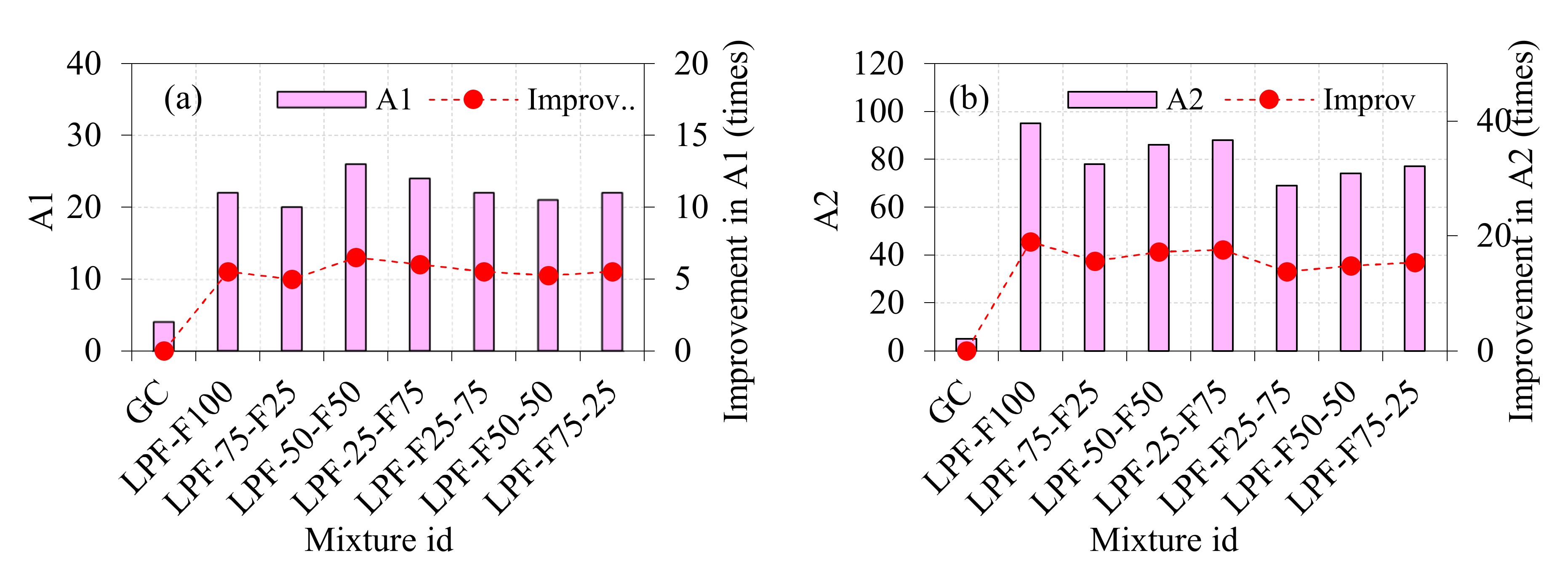
3.2.2. Influence of LPF on the Impact Strength of GFC

Positive impact strength of the composite was observed with the addition of LPF to two-layered GFC, shown in Figure 8. Regarding the findings obtained in two-layered GFC, it is clear from Figure 8 that the greater the depth of fibrous layers, the greater the A1 and A2 values of FGC specimens. The impact strength augmentation in the second series specimens is explained in the following manner when compared to the GC specimens:
  • The A1 and A2 values for the LPF-F100 specimens were recorded as 22 and 95, respectively, and these values were 5.5 and 19 times higher than those for the GC specimens, respectively.
  • The recorded values for the LPF-75-F25 specimen were 20 and 78, which corresponded to the A1 and A2 subtypes, respectively. For A1 and A2, improvements of 5.0 and 15.6 times were seen, respectively.
  • It was noted that the A1 and A2 values recorded for the LPF-50-F50 specimens were 26 and 86, respectively. This indicates a 3.75- and 11.2-fold increase compared to the GC values.
  • The A1 and A2 values for the LPF-25-F75 specimens were 24 and 88, respectively, which were 6.0 and 17.6 times more than those of the GC specimens.
  • The A1 and A2 values of LPF-F25-75 specimens were 22 and 69, respectively, which were 5.5 and 13.8 times more than those of GC.
  • For LPF-F50-50 specimens, the measurement results for A1 and A2 were 21 and 74, respectively. However, A1 and A2 showed increases of 5.25 and 14.8 times, respectively.
  • The values associated with A1 and A2 for the LPF-F75-25 specimen were 22 and 77, respectively, as recorded. The highest improvements were in A1 and A2, with increases of 5.5 and 15.4 times, respectively.
This clearly shows the effect of GFC with two layers reinforced with LPF, emphasizing the ductile mode of breaking against drop weight impact, rather than early brittle failure. However, two-layered GFC exhibited a lesser impact strength compared to single-layered GFC. This phenomenon is due to the greater amount of LPF uniformly distributed along the cracking path to the full depth of the specimen, resulting in higher impact energy absorbance ability. The layered specimen having a fibre depth of 25–75% led to an effective promotion of the adhesion between the fibres and the surrounding matrix at the designed depth, leading to a rise in impact strength and the prevention of fibres from pulling away from the matrix. The contact point of the specimen with a drop hammer influences the impact strength. A greater number of fibres existing in the top layers can significantly improve the first crack resistance and postpone the crack propagation. However, the crack reaches the depth of the fibrous first layer and immediately propagates through the bottom layer due to the absence of the fibre in the second layer. The specimen with GC in the top layer and GFC in the bottom layer can quickly trigger the first crack due to the plain GC provided in the top layer. When the crack reaches the bottom of the first layer, its propagation to the specimen’s bottom surface is further delayed due to the bridging action of the fibre. This unquestionably improved the behaviour of crack inhibition and the effectiveness of the crack limitation. It was noticed that tensile stress had been transferred along broken sections in the top layer of the GFC or GC, and, therefore, a higher impact strength was recorded. Under impact stress, cracks began to form on the cylindrical disc’s top surface and spread to the bottom. As a result of its fibre bridging ability, the bottom layer comprised of LPF performed better than the top layer comprised LPF in terms of impact performance. This may be because of LPF’s ability to postpone crack propagation by increasing fibre bridging before the failure stage.

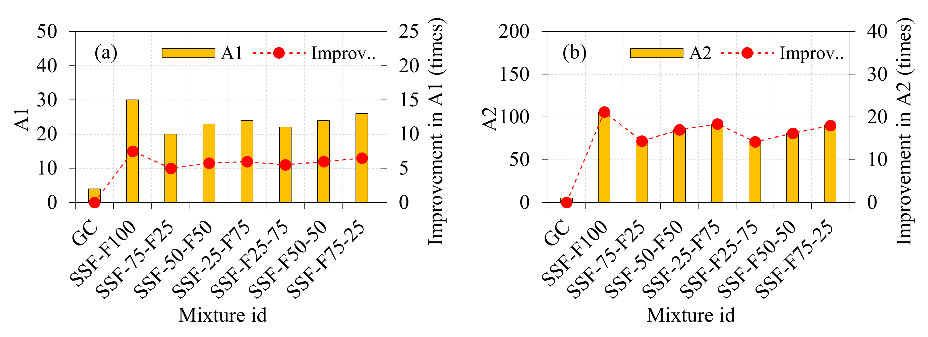
3.2.3. Influence of SSF on the Impact Strength of GFC

Figure 9 shows the enhanced impact strength of the composite when LPF was added to the two-layered GFC. Figure 9 shows that the greater the depth of fibrous layers, the larger the A1 and A2 values of FGC specimens produced in two-layered GFC. Compared to the GC specimens, the increased impact strength in the third series of specimens may be explained as follows:
  • For the SSF-F100 specimens, the A1 and A2 values were recorded as 30 and 106, respectively, and these values were 7.5 and 21.2 times higher than the corresponding values for the GC specimens.
  • When the SSF-75-F25 specimen was tested, the recorded values were 20 and 72, belonging to A1 and A2 respectively. Improvements in A1 and A2 were around 5.0 and 14.4 times, respectively.
  • A1 and A2 values recorded for the SSF-50-F50 specimens were 23 and 85, respectively, according to the test results, which were 5.75 and 17 times higher than the GC values, respectively.
  • In the case of the SSF-25-F75 specimens, the A1 and A2 values were 24 and 92, respectively, which were 6.0 and 18.4 times higher than those of the GC specimens.
  • SSF-F25-75 specimens had A1 and A2 values of 22 and 71, respectively, which were 5.5 and 14.2 times more than those of GC.
  • Results for A1 and A2 were 24 and 81, respectively for SSF-F50-50 specimens. Increases of 6.0 and 16.2 times were seen in A1 and A2, respectively.
  • The values associated with A1 and A2 for the SSF-F75-25 specimen were 26 and 90, respectively, as recorded. The highest improvements were in A1 and A2, with increases of 6.5 and 18 times, respectively.
It is evident from the above discussion that SSF addition into a GFC showed a significant improvement in impact strength. The specimen with 100% depth of GFC exhibited an excellent impact resistance compared to the 25–75% depth of GFC. The results highlighted that the GFC comprising a 25–75% depth in the bottom layer increased the impact strength marginally compared to the GFC 25–75% provided in the top layer. The presence of SSF in the top layer can resist the crack initiation for a certain period. Hence, more time is required to propagate the crack from the top of the layer to the bottom. When the crack reaches the bottom layer, it quickly propagates to the specimen’s bottom surface due to the absence of fibres. This phenomenon is reversed in the specimens comprising GF in the top layer and GFC in the bottom layers; for example, the SSF-75-F25 specimen comprising 75% of GC in the top layer and the remaining 25% of GFC at the bottom layer. The steel hammer created a contact impact on the specimen top surface (top layer), leading to quick crack initiation due to the absence of fibre. This crack propagation was slowed when it crossed the bottom layer due to the fibre bridging action. This large augmentation of impact energy is mostly ascribed to the crack arresting capacity of SSF as a result of their hooked ends, which provide more adhesion to the matrix, allowing for more stress transfer between the SSF and the surrounding matrix [45]. As a result, the steel fibres maintain the link between the two sides of the crack. The bonding sections of the specimens become larger as the lengths of the steel fibres in the specimens become longer [46]. In conclusion, the development of the initial crack was delayed in the case of specimens comprised of SSF in top layers. After each blow, the tensile stress resistance of SSF increases as the width and length of the cracks increases, although two sections of the fractures are still bridged by SSF as the crack widths and lengths increase [47]. This delayed the failure of specimens due to multiple impacts until the link between SSF and matrix was broken, with the pulling out of SSF being the most prevalent kind of failure [48,49,50].

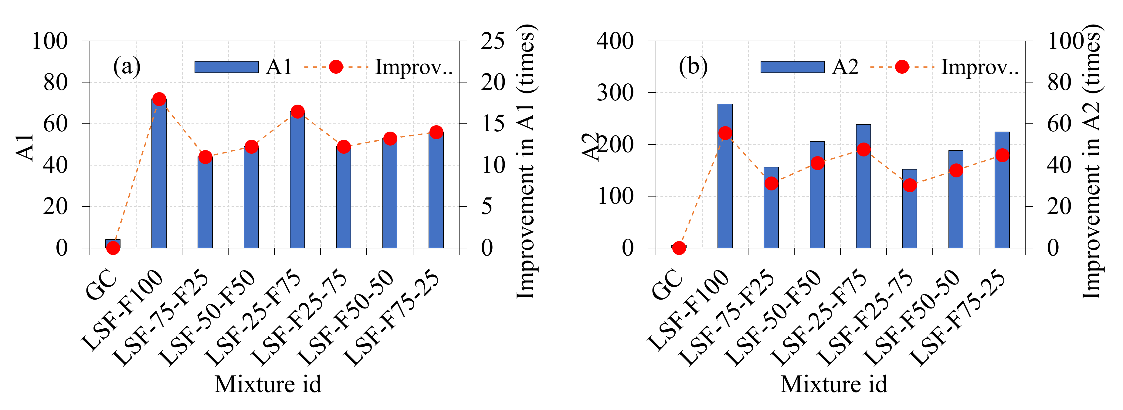
3.2.4. Influence of LSF on the Impact Strength of LGFC

When LSF was introduced to the two-layered GFC, the composite’s impact strength improved significantly. The A1 and A2 values of GFC specimens generated in two-layered GFC increase as the depth of the fibrous layers increases (see Figure 10). The enhanced impact strength in the third series of specimens may be explained in the following manner compared to the GC specimens:
  • The recorded A1 and A2 values for the LSF-F100 specimens were 72 and 278, respectively, and these values were 18 and 55.6 times higher than those of GC.
  • The recorded values for the LSF-75-F25 specimen were 44 and 156, which corresponded to the A1 and A2 subtypes, respectively. For A1 and A2, improvements of 11.0 and 31.2 times were seen, respectively.
  • A1 and A2 values recorded for the LSF-50-F50 specimens were 49 and 205, respectively, according to the test results, which were 12.25 and 41 times higher than the GC values, respectively.
  • The A1 and A2 values for the LSF-25-F75 specimens were recorded as 66 and 238, respectively, and these values were 16.5 and 47.6 times higher than those for the GC specimens, respectively.
  • The A1 and A2 values of LSF-F25-75 specimens were 49 and 152, respectively, which were 12.25 and 30.40 times more than those of GC.
  • Results for A1 and A2 were 53 and 188, respectively, for LSF-F50-50 specimens. Increases of 13.25 and 37.6 times were seen in A1 and A2, respectively.
  • For the LSF-F75-25 specimen, the values associated with A1 and A2 were 56 and 224, respectively, as recorded. A1 and A2 had the greatest gains, with increases of 14.0 and 44.8 times, respectively.
From the above discussion, it was clearly observed that the LSF based specimens exhibited an excellent impact strength compared to the SPF-, LPF- and SSF-based specimens. The trend of increasing impact strength for the two-layered specimens is the same as the trend discussed in the earlier sections (Section 3.2.1, Section 3.2.2 and Section 3.2.3). It is evident from the results that the LSF-based specimens had better impact performance than SSF-based specimens due to stronger pull-out resistance caused by longer development lengths within the matrix [51]. Higher steel fibre lengths were also shown to be more effective for improving impact, flexural and tensile properties [52,53,54]. In summary, the performance of LSF is much better than that of SSF in terms of impact strength. This is ascribed to the shorter length of the fibres, which are thus incapable of acting as a “bridge” for a major breakdown (about 5 mm) in the event of serious damage. Micro-cracking regimes may benefit from this SSF, but their inability to bridge macro-cracks may restrict their usefulness [55]. However, LSF was very effective in preventing macro-cracks through the effective bridging action of fibres. The increase in the depth of fibrous layers from 25 to 100% resulted in higher impact strength for all four types of fibres. The impact performance of LSF was the most remarkable, followed by that of SSF, LPF and SPF.
Another cause of the increase in the impact strength is the usage of material having a high SiO2 content when producing GC. The GGFBS has a greater specific surface area, which means it has a higher heat of hydration, which aids in the early development of concrete strength [56]. The increased impact strength was achieved by the incorporation of slag into FA-based alkali-activated concrete as a consequence of the increased C–S–H production and polymerization products [57]. The presence of GGBFS and CaO in the solution has been documented in previous research to speed up the polymerization process. This results in the release of heat, which in turn contributes to the production of gels such as C–S–H and N–A–S–H/N–S–H gels. This leads to a strong improvement in GC.
The comparison of the impact strength of plain concrete and geopolymer concrete, with and without fibre, is demonstrated in Table 5. The results recorded in this study aligned well with those in the earlier literature. However, certain parameters influence the impact strength of concrete, such as compressive strength, fibre length, fibre dosage, fibre type and fibre shape.

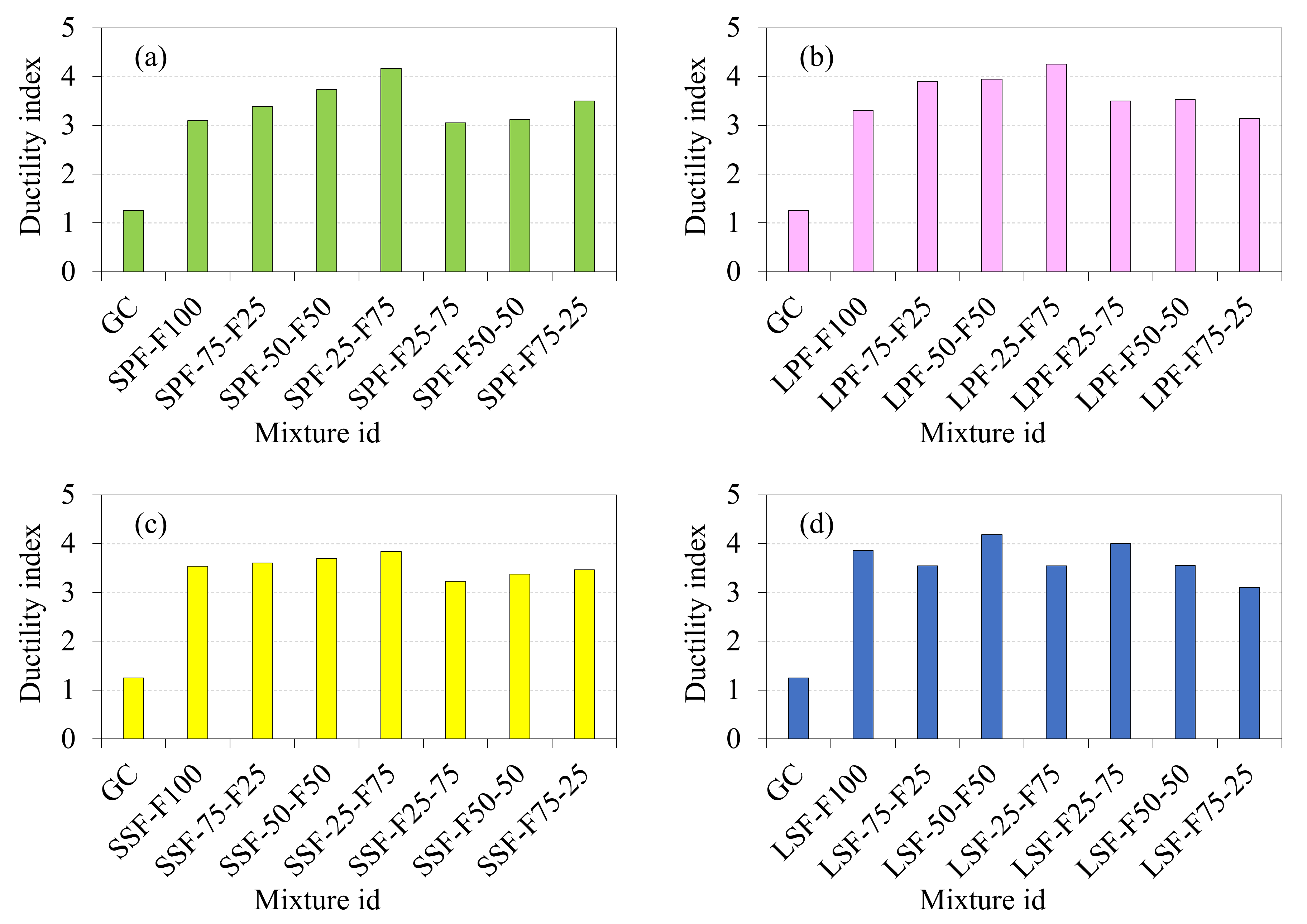
3.2.5. Impact Ductility Index

For reinforced concrete beams subjected to three- or four-point loading, flexural ductility is assessed by dividing the deflection at the failure by the yield of steel reinforcement, which is then used to evaluate the beam’s ability to bear plastic deformations. Using a similar approach, the introduced mixes’ resistance to repeated impacts following surface cracking was also evaluated in this paper. IDI was defined in earlier research [47,62,63] as the ratio of the failure impact number to the cracking impact number, and this definition was also utilized in the current study, where IDI equals the ratio of A2 to A1 for each combination. Figure 11 depicts the IDI values of four series specimens. The IDI value of the first series specimen comprised SPF values ranging from 3.05 to 4.17. For the second series specimens, the IDI values ranged from 3.14 to 4.32, which indicates the LPF based specimens exhibited better post-crack resistance than the SPF-based specimens. This was because of the positive influence of fibres, not only on increasing A1 and A2, but also on their capacity to increase the number of hits before failure occurred following surface cracking. The IDI values from the third and fourth series specimens ranged from 3.23 to 3.53, and from 3.1 to 4.18, respectively. It was also recorded that, in most cases, increasing the depth of the fibrous layer led to a higher ductility value.

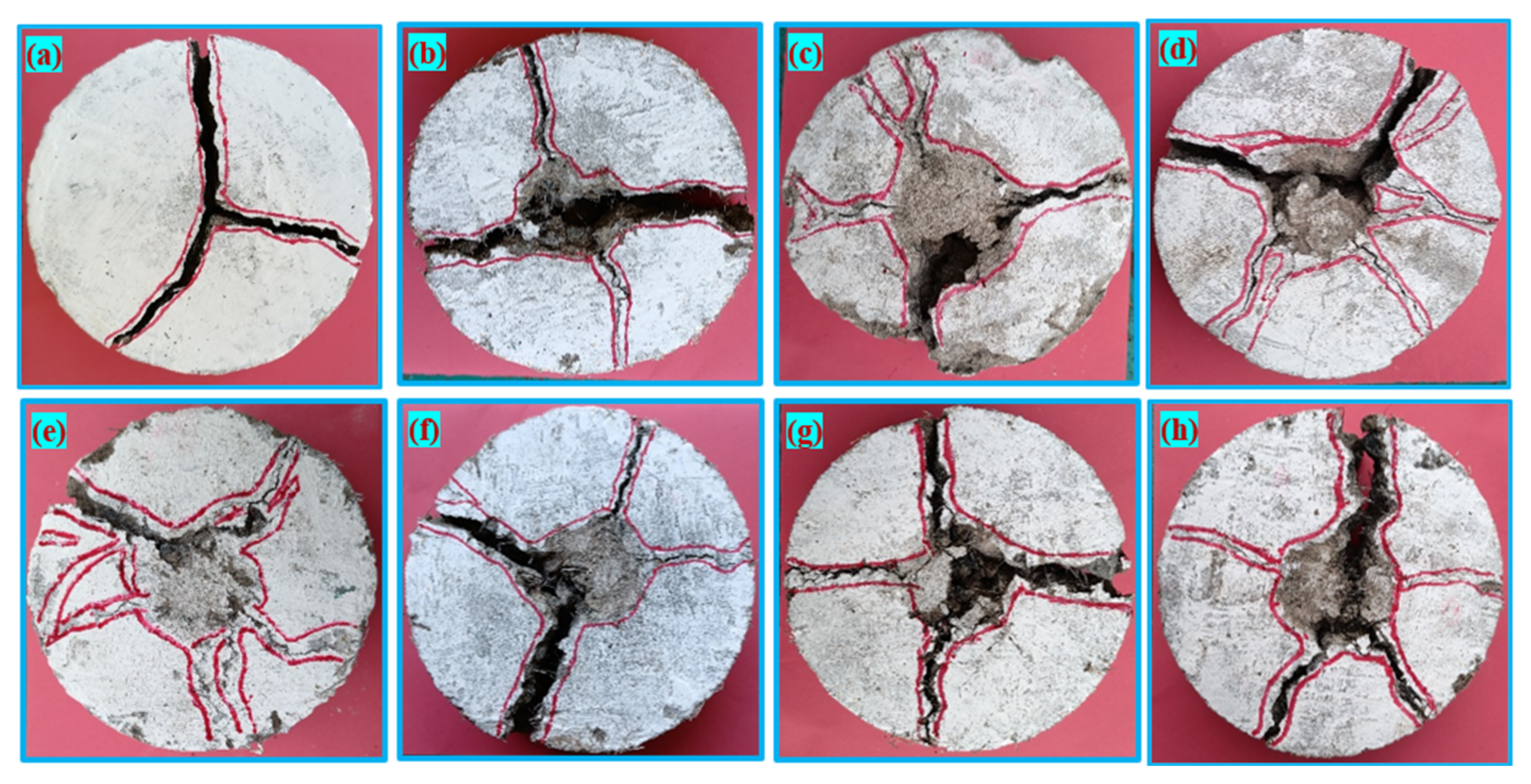
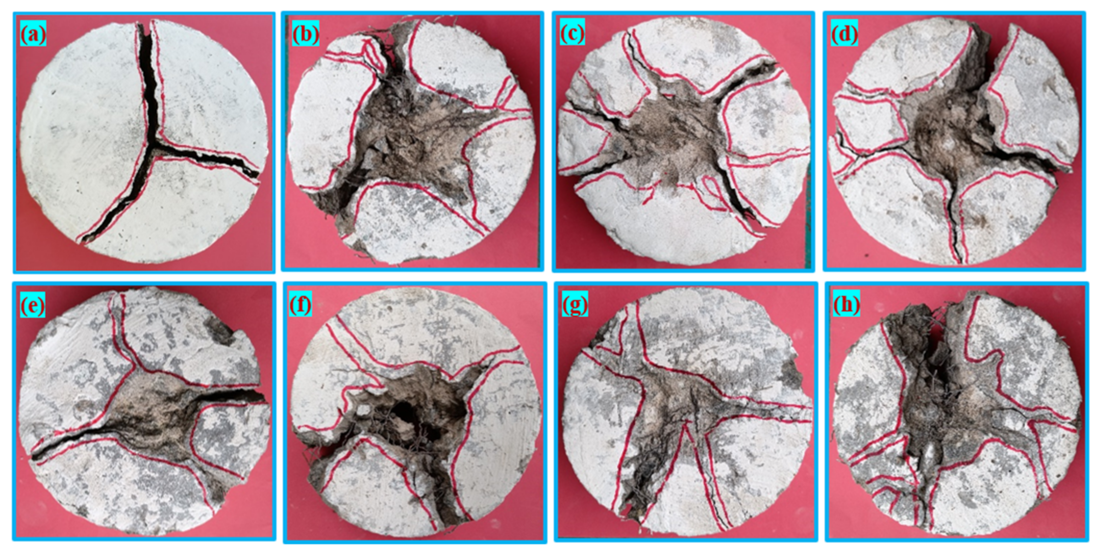
3.2.6. Failure Pattern

Figure 12 and Figure 13 show the fractures on the top surfaces of all tested mixtures after failure. The first observation was recorded after the comparison between Figure 12a and Figure 13a for the reference specimens (GC) and Figure 12b–h and Figure 13b–h for the fibrous specimens. Under repeated impact, the more ductile behaviour of fibrous samples may be seen in the larger fracture zone, whereas the direct and uniform breaking of GC specimens indicates their brittle character. Fibres and their reinforcing action can redirect tensile stresses on different paths by crack bridging, which provides stress relief for the concrete matrix. This behaviour is associated with some radial cracks in the specimens’ top surface. The ductile fracture of fibre-reinforced specimens was attributed to the perfect bond with the surrounding matrix, due to the strong bond along the fibres [64,65,66,67]. Two-layered specimens comprising GC in the top layer and GFC in the bottom layer exhibited a ductile failure, and single cracks could be turned into multiple cracks [68,69]; hence, the brittleness was reduced significantly.

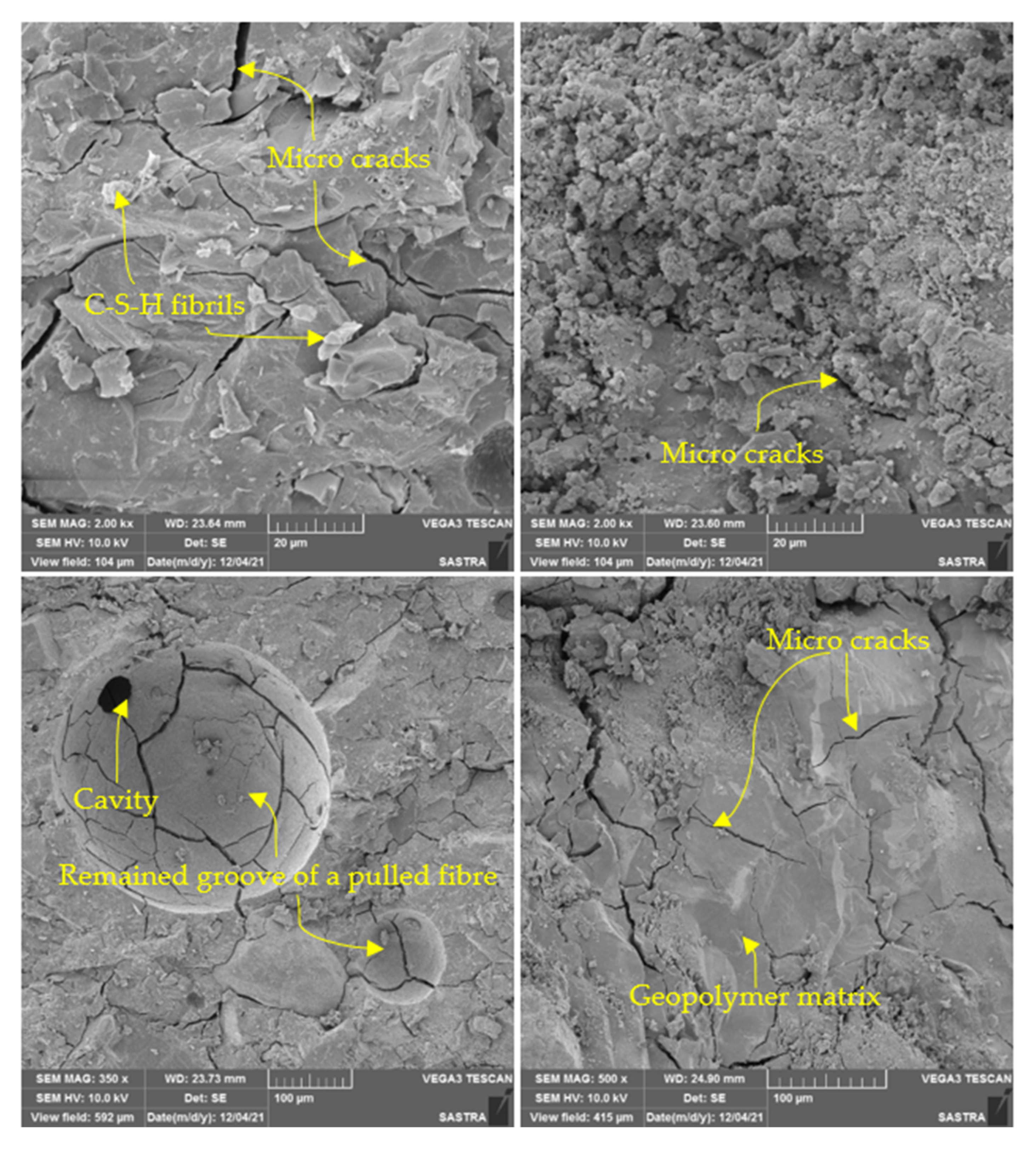
3.2.7. Scanning Electron Microscope

Figure 14 illustrates the SEM images of the geopolymer matrix. The fracture surface of the examined GFC specimens, which were inspected at various magnifications, revealed many interesting facts. As shown at a magnification of 20 and 100 µm in Figure 14, an agglomerate particle break is connected with a crack. Nevertheless, the crack is prevented at the interface with the geopolymeric matrix, which indicates impact resistance. Fibrous CaO·SiO2·H2O (C–S–H) crystals are also observed in Figure 14 and C–S–H crystals contribute to reinforcing the geopolymer. The ubiquity of fibres suggests that there will be more fibre pull-out because those fibres dragged out of their respective cavities will now occupy the interface. This observation is consistent with the abundance of voids and grooves (leftover following fibre pull-out) in the geopolymer matrix (see Figure 14). It was also possible to detect a trace of the porous layer that existed at the matrix-fibre interface; this was referred to as a “fibre fossil”.

4. Conclusions

According to the current literature, geopolymer concrete (GC) is a viable alternative for traditional cement concrete. Nevertheless, the opportunity for the implementation and advancement of layered geopolymer fibrous concrete (GFC) must be broadened to achieve greater success. This study focused on investigating the impact performance of layered composite comprising GFC at the tension zone and GC at the compression zone, and vice versa. The following is a summary of the findings from this study:
  • The highest compressive strength improvements observed were 73.88, 50.15, 35.82 and 14.5% for the LSF, SSF, LPF and SPF based on single-layered specimens, respectively. Comparing the performance of the four different fibres, LSF exhibited a significant improvement in strength. However, the layered specimens also influenced the positive impact on compressive strength, particularly for LSF, followed by SSF, LPF and SPF.
  • For single-layered concrete, the highest impact energy was exhibited by the LSF-F100 specimen, followed by SSF-F100, LPF-F100 and SPF-F100 specimens. Compared to the GC specimen, the A1 values were improved by 55.6, 21.2, 19 and 13.6%, respectively. The higher impact strength is due to LSF with hooked ends, which provides stronger adhesion to the matrix and allows for higher stress transfer between the LSF and the surrounding matrix. For the two-layered specimens, when the depth of the fibrous layer at the bottom was increased from 25 to 75%, the impact strength was significantly improved for all four types of fibres. However, the performance of two-layered specimens was significantly lower compared to a single-layered specimen. Additionally, the contribution of LSF in increasing impact strength was greater than that in the other three types of fibres.
  • Altering the depth in the fibrous layer of the specimens from 25 to 75% resulted in moderate impact strength, which occurred for fibrous specimen having a depth of close to 100%. In this regard, the cost of fibres can be minimized by providing two layers with GC and GFC, without compromising the strength to the maximum extent. Hence, two-layer concrete can be implemented in practice based on the design requirements, and provides improved ductility.
  • The failure that occurred was brittle in the GC specimens, in which the specimens were broken into three parts, whereas all fibrous specimens reflected a ductile nature. This failure pattern was similar in both single- and double-layered composites, irrespective of the fibre type. Adding fibres to GC can change the single main cracks into multiple radial cracks, which have a positive impact on fibrous concrete.

Author Contributions

Conceptualization, S.K. and K.S.R.M.; methodology, S.K., K.S.R.M.; software, S.K., K.S.R.M.; validation, S.K., K.S.R.M.; formal analysis, S.K. and K.S.R.M.; investigation, S.K., K.S.R.M.; resources, S.K., K.S.R.M.; data curation, S.K. and K.S.R.M.; writing—original draft preparation, S.K., K.S.R.M., G.M.; writing—review and editing, S.K., K.S.R.M., G.M.; visualization, S.K., K.S.R.M.; supervision, K.S.R.M.; project administration, S.K., K.S.R.M.; funding acquisition, S.K., K.S.R.M. All authors have read and agreed to the published version of the manuscript.

Funding

This research received no external funding.

Institutional Review Board Statement

Not applicable.

Informed Consent Statement

Not applicable.

Data Availability Statement

Not applicable.

Acknowledgments

Authors are grateful to the School of Civil Engineering, SASTRA Deemed University for the support.

Conflicts of Interest

The authors declare no conflict of interest.

References

  1. Nikbakht, E.; Wong Weng Lok, J.; Teo, W. Structural behaviour of novel composite beams consisting of geopolymer concrete and high-performance concrete. Structures 2021, 32, 106–115. [Google Scholar] [CrossRef]
  2. Wang, L.; Zeng, X.; Yang, H.; Lv, X.; Guo, F.; Shi, Y.; Hanif, A. Investigation and Application of Fractal Theory in Cement-Based Materials: A Review. Fractal Fract. 2021, 5, 247. [Google Scholar] [CrossRef]
  3. Wang, L.; Luo, R.; Zhang, W.; Jin, M.; Tang, S. Effects of fineness and content of phosphorus slag on cement hydration, permeability, pore structure and fractal dimension of concrete. Fractals 2021, 29, 2140004. [Google Scholar] [CrossRef]
  4. Wang, L.; Jin, M.; Guo, F.; Wang, Y.A.N.; Tang, S. Pore structural and fractal analysis of the influence of fly ash and silica fume on the mechanical property and abrasion resistance of concrete. Fractals 2021, 29, 2140003. [Google Scholar] [CrossRef]
  5. Nazari, A.; Sanjayan, J.G. Handbook of Low Carbon Concrete; Butterworth-Heinemann: Oxford, UK, 2016; ISBN 9780128045404. [Google Scholar]
  6. Khale, D.; Chaudhary, R. Mechanism of geopolymerization and factors influencing its development: A review. J. Mater. Sci. 2007, 42, 729–746. [Google Scholar] [CrossRef]
  7. Hassan, A.; Arif, M.; Shariq, M. Use of geopolymer concrete for a cleaner and sustainable environment—A review of mechanical properties and microstructure. J. Clean. Prod. 2019, 223, 704–728. [Google Scholar] [CrossRef]
  8. Hassan, A.; Arif, M.; Shariq, M. A review of properties and behaviour of reinforced geopolymer concrete structural elements- A clean technology option for sustainable development. J. Clean. Prod. 2020, 245, 118762. [Google Scholar] [CrossRef]
  9. Ferdous, W.; Manalo, A.; Khennane, A.; Kayali, O. Geopolymer concrete-filled pultruded composite beams—Concrete mix design and application. Cem. Concr. Compos. 2015, 58, 1–13. [Google Scholar] [CrossRef]
  10. Albitar, M.; Mohamed Ali, M.S.; Visintin, P. Experimental study on fly ash and lead smelter slag-based geopolymer concrete columns. Constr. Build. Mater. 2017, 141, 104–112. [Google Scholar] [CrossRef]
  11. Santhakumar, A.; Ganesan, N.; Indira, P.V. Bond behaviour of reinforcing bars embedded in steel fibre reinforced geopolymer concrete. Mag. Concr. Res. 2015, 67, 9–16. [Google Scholar]
  12. Abid, S.R.; Murali, G.; Amran, M.; Vatin, N.; Fediuk, R.; Karelina, M. Evaluation of mode II fracture toughness of hybrid fibrous geopolymer composites. Materials 2021, 14, 349. [Google Scholar] [CrossRef]
  13. Ranjbar, N.; Zhang, M. Fiber-reinforced geopolymer composites: A review. Cem. Concr. Compos. 2020, 107, 103498. [Google Scholar] [CrossRef]
  14. Noushini, A.; Hastings, M.; Castel, A.; Aslani, F. Mechanical and flexural performance of synthetic fibre reinforced geopolymer concrete. Constr. Build. Mater. 2018, 186, 454–475. [Google Scholar] [CrossRef]
  15. Khan, M.Z.N.; Hao, Y.; Hao, H.; Shaikh, F.u.A. Mechanical properties and behaviour of high-strength plain and hybrid-fiber reinforced geopolymer composites under dynamic splitting tension. Cem. Concr. Compos. 2019, 104, 103343. [Google Scholar] [CrossRef]
  16. Payakaniti, P.; Pinitsoontorn, S.; Thongbai, P.; Amornkitbamrung, V.; Chindaprasirt, P. Electrical conductivity and compressive strength of carbon fiber reinforced fly ash geopolymeric composites. Constr. Build. Mater. 2017, 135, 164–176. [Google Scholar] [CrossRef]
  17. Rovnaník, P.; Šimonová, H.; Topolář, L.; Bayer, P.; Schmid, P.; Keršner, Z. Carbon nanotube reinforced alkali-activated slag mortars. Constr. Build. Mater. 2016, 119, 223–229. [Google Scholar] [CrossRef]
  18. Ranjbar, N.; Mehrali, M.; Mehrali, M.; Alengaram, U.J.; Jumaat, M.Z. Graphene nanoplatelet-fly ash based geopolymer composites. Cem. Concr. Res. 2015, 76, 222–231. [Google Scholar] [CrossRef]
  19. Sukontasukkul, P.; Pongsopha, P.; Chindaprasirt, P.; Songpiriyakij, S. Flexural performance and toughness of hybrid steel and polypropylene fibre reinforced geopolymer. Constr. Build. Mater. 2018, 161, 37–44. [Google Scholar] [CrossRef]
  20. Mohseni, E.; Kazemi, M.J.; Koushkbaghi, M.; Zehtab, B.; Behforouz, B. Evaluation of mechanical and durability properties of fiber-reinforced lightweight geopolymer composites based on rice husk ash and nano-alumina. Constr. Build. Mater. 2019, 209, 532–540. [Google Scholar] [CrossRef]
  21. Shaikh, F.U.A. Deflection hardening behaviour of short fibre reinforced fly ash based geopolymer composites. Mater. Des. 2013, 50, 674–682. [Google Scholar] [CrossRef] [Green Version]
  22. Ganesan, N.; Indira, P.V.; Santhakumar, A. Engineering properties of steel fibre reinforced geopolymer concrete. Adv. Concr. Constr. 2013, 1, 305–318. [Google Scholar] [CrossRef] [Green Version]
  23. Patil, S.S.; Patil, A.A. Properties of Polypropylene Fiber Reinforced Geopolymer Concrete. Int. J. Curr. Eng. Technol. 2015, 5, 2909–2912. [Google Scholar]
  24. Li, W.; Xu, J. Impact characterization of basalt fiber reinforced geopolymeric concrete using a 100-mm-diameter split Hopkinson pressure bar. Mater. Sci. Eng. A 2009, 513–514, 145–153. [Google Scholar] [CrossRef]
  25. Jacob, M.; Bharatkumar, B.H.; Rajendran, M.G. Studies on the Impact Behaviour of Fiber Reinforced Geopolymer Concrete. Int. J. Adv. Technol. Eng. Sci. 2015, 3, 376–386. [Google Scholar]
  26. Puertas, F.; Amat, T.; Vázquez, T. Behaviour of alkaline cement mortars reinforced with acrylic and polypropylene fibres. Mater. Constr. 2000, 2000, 69–84. [Google Scholar] [CrossRef] [Green Version]
  27. Ulzurrun, G.S.D.; Zanuy, C. Enhancement of impact performance of reinforced concrete beams without stirrups by adding steel fibers. Constr. Build. Mater. 2017, 145, 166–182. [Google Scholar] [CrossRef]
  28. Asrani, N.P.; Murali, G.; Parthiban, K.; Surya, K.; Prakash, A.; Rathika, K.; Chandru, U. A feasibility of enhancing the impact resistance of hybrid fibrous geopolymer composites: Experiments and modelling. Constr. Build. Mater. 2019, 203, 56–68. [Google Scholar] [CrossRef]
  29. Cao, Y.Y.Y.; Liu, G.; Brouwers, H.J.H.; Yu, Q. Enhancing the low-velocity impact resistance of ultra-high performance concrete by an optimized layered-structure concept. Compos. Part B Eng. 2020, 200, 108221. [Google Scholar] [CrossRef]
  30. Prasad, N.; Murali, G.; Abid, S.R.; Vatin, N.; Fediuk, R.; Amran, M. Effect of Needle Type, Number of Layers on FPAFC Composite against Low-Velocity Projectile Impact. Buildings 2021, 11, 668. [Google Scholar] [CrossRef]
  31. ASTM C618-08; Standard Specification for Coal Fly Ash and Raw or Calcined Natural Pozzolan for Use in Concrete. American Society for Testing and Materials: West Conshohocken, PA, USA, 2008.
  32. Karthik, S.; Mohan, K.S.R. A taguchi approach for optimizing design mixture of geopolymer concrete incorporating fly ash, ground granulated blast furnace slag and silica fume. Crystals 2021, 11, 1279. [Google Scholar] [CrossRef]
  33. IS 383; Coarse and Fine Aggregate for Concrete Specification. Bureau of Indian Standards: New Delhi, India, 2016. Available online: https://archive.org/details/gov.in.is.383.2016/page/n1/mode/2up (accessed on 27 December 2021).
  34. Ahmad, S.H.; Arockiasamy, M.; Balaguru, P.N.; Ball, C.G.; Ball, H.P., Jr.; Batson, G.B.; Bentur, A.; Craig, R.J.; Criswell, M.E.; Freedman, S.; et al. Measurement of Properties of Fiber Reinforced Concrete; ACI 544-2R; American Concrete Institute: Indianapolis, IN, USA, 1999. [Google Scholar]
  35. ASTM C39/C39M-21; Standard Test Method for Compressive Strength of Cylindrical Concrete Specimens. ASTM International: West Conshohocken, PA, USA, 2004.
  36. Karimipour, A.; de Brito, J. Influence of polypropylene fibres and silica fume on the mechanical and fracture properties of ultra-high-performance geopolymer concrete. Constr. Build. Mater. 2021, 283, 122753. [Google Scholar] [CrossRef]
  37. Yoo, D.Y.; Kim, S.; Park, G.J.; Park, J.J.; Kim, S.W. Effects of fiber shape, aspect ratio, and volume fraction on flexural behavior of ultra-high-performance fiber-reinforced cement composites. Compos. Struct. 2017, 174, 375–388. [Google Scholar] [CrossRef]
  38. Rithanyaa, R.; Murali, G.; Salaimanimagudam, M.P.; Fediuk, R.; Abdelgader, H.S.; Siva, A. Impact response of novel layered two stage fibrous composite slabs with different support type. Structures 2021, 29, 1–13. [Google Scholar] [CrossRef]
  39. Liu, Y.; Zhang, Z.; Shi, C.; Zhu, D.; Li, N.; Deng, Y. Development of ultra-high performance geopolymer concrete (UHPGC): Influence of steel fiber on mechanical properties. Cem. Concr. Compos. 2020, 112, 103670. [Google Scholar] [CrossRef]
  40. Murali, G.; Asrani, N.P.; Ramkumar, V.R.; Siva, A.; Haridharan, M.K. Impact Resistance and Strength Reliability of Novel Two-Stage Fibre-Reinforced Concrete. Arab. J. Sci. Eng. 2019, 44, 4477–4490. [Google Scholar] [CrossRef]
  41. Afroughsabet, V.; Ozbakkaloglu, T. Mechanical and durability properties of high-strength concrete containing steel and polypropylene fibers. Constr. Build. Mater. 2015, 94, 73–82. [Google Scholar] [CrossRef]
  42. Ramakrishnan, K.; Depak, S.R.; Hariharan, K.R.; Abid, S.R.; Murali, G.; Cecchin, D.; Fediuk, R.; Mugahed Amran, Y.H.; Abdelgader, H.S.; Khatib, J.M. Standard and modified falling mass impact tests on preplaced aggregate fibrous concrete and slurry infiltrated fibrous concrete. Constr. Build. Mater. 2021, 298, 123857. [Google Scholar] [CrossRef]
  43. Ramkumar, V.R.; Murali, G.; Asrani, N.P.; Karthikeyan, K. Development of a novel low carbon cementitious two stage layered fibrous concrete with superior impact strength. J. Build. Eng. 2019, 25, 100841. [Google Scholar] [CrossRef]
  44. Asrani, N.P.; Murali, G.; Abdelgader, H.S.; Parthiban, K.; Haridharan, M.K.; Karthikeyan, K. Investigation on Mode I Fracture Behavior of Hybrid Fiber-Reinforced Geopolymer Composites. Arab. J. Sci. Eng. 2019, 44, 8545–8555. [Google Scholar] [CrossRef]
  45. Niş, A.; Özyurt, N.; Özturan, T. Variation of Flexural Performance Parameters Depending on Specimen Size and Fiber Properties. J. Mater. Civ. Eng. 2020, 32, 4020054. [Google Scholar] [CrossRef]
  46. Murali, G.; Fediuk, R. A Taguchi approach for study on impact response of ultra-high-performance polypropylene fibrous cementitious composite. J. Build. Eng. 2020, 30, 101301. [Google Scholar] [CrossRef]
  47. Abid, S.R.; Gunasekaran, M.; Ali, S.H.; Kadhum, A.L.; Al-Gasham, T.S.; Fediuk, R.; Vatin, N.; Karelina, M. Impact performance of steel fiber-reinforced self-compacting concrete against repeated drop weight impact. Crystals 2021, 11, 91. [Google Scholar] [CrossRef]
  48. Abirami, T.; Murali, G.; Saravana Raja Mohan, K.; Salaimanimagudam, M.P.; Nagaveni, P.; Bhargavi, P. Multi-layered two stage fibrous composites against low-velocity falling mass and projectile impact. Constr. Build. Mater. 2020, 248, 118631. [Google Scholar] [CrossRef]
  49. Manohar, T.; Suribabu, C.R.; Murali, G.; Salaimanimagudam, M.P. A novel steel-PAFRC composite fender for bridge pier protection under low velocity vessel impacts. Structures 2020, 26, 765–777. [Google Scholar] [CrossRef]
  50. Haridharan, M.K.; Matheswaran, S.; Murali, G.; Abid, S.R.; Fediuk, R.; Mugahed Amran, Y.H.; Abdelgader, H.S. Impact response of two-layered grouted aggregate fibrous concrete composite under falling mass impact. Constr. Build. Mater. 2020, 263, 120628. [Google Scholar] [CrossRef]
  51. Niş, A.; Eren, N.A.; Çevik, A. Effects of nanosilica and steel fibers on the impact resistance of slag based self-compacting alkali-activated concrete. Ceram. Int. 2021, 47, 23905–23918. [Google Scholar] [CrossRef]
  52. Murali, G.; Ramprasad, K. A feasibility of enhancing the impact strength of novel layered two stage fibrous concrete slabs. Eng. Struct. 2018, 175, 41–49. [Google Scholar] [CrossRef]
  53. Abirami, T.; Loganaganandan, M.; Murali, G.; Fediuk, R.; Vickhram Sreekrishna, R.; Vignesh, T.; Januppriya, G.; Karthikeyan, K. Experimental research on impact response of novel steel fibrous concretes under falling mass impact. Constr. Build. Mater. 2019, 222, 447–457. [Google Scholar] [CrossRef]
  54. Salaimanimagudam, M.P.; Suribabu, C.R.; Murali, G.; Abid, S.R. Impact response of hammerhead pier fibrous concrete beams designed with topology optimization. Period. Polytech. Civ. Eng. 2020, 64, 1244–1258. [Google Scholar] [CrossRef]
  55. Rezakhani, R.; Scott, D.A.; Bousikhane, F.; Pathirage, M.; Moser, R.D.; Green, B.H.; Cusatis, G. Influence of steel fiber size, shape, and strength on the quasi-static properties of ultra-high performance concrete: Experimental investigation and numerical modeling. Constr. Build. Mater. 2021, 296, 123532. [Google Scholar] [CrossRef]
  56. Aliabdo, A.A.; Abd Elmoaty, A.E.M.; Salem, H.A. Effect of water addition, plasticizer and alkaline solution constitution on fly ash based geopolymer concrete performance. Constr. Build. Mater. 2016, 121, 694–703. [Google Scholar] [CrossRef]
  57. Mehta, A.; Siddique, R.; Ozbakkaloglu, T.; Uddin Ahmed Shaikh, F.; Belarbi, R. Fly ash and ground granulated blast furnace slag-based alkali-activated concrete: Mechanical, transport and microstructural properties. Constr. Build. Mater. 2020, 257, 119548. [Google Scholar] [CrossRef]
  58. Chen, X.Y.; Ding, Y.N.; Azevedo, C. Combined effect of steel fibres and steel rebars on impact resistance of high performance concrete. J. Cent. South Univ. Technol. 2011, 18, 1677–1684. [Google Scholar] [CrossRef] [Green Version]
  59. Alwesabi, E.A.; Abu Bakar, B.H.; Alshaikh, I.M.H.; Akil, H.M. Impact resistance of plain and rubberized concrete containing steel and polypropylene hybrid fiber. Mater. Today Commun. 2020, 25, 101640. [Google Scholar] [CrossRef]
  60. Nili, M.; Afroughsabet, V. Combined effect of silica fume and steel fibers on the impact resistance and mechanical properties of concrete. Int. J. Impact Eng. 2010, 37, 879–886. [Google Scholar] [CrossRef] [Green Version]
  61. Mohammadhosseini, H.; Tahir, M.M.; Sam, A.R.M. The feasibility of improving impact resistance and strength properties of sustainable concrete composites by adding waste metalized plastic fibres. Constr. Build. Mater. 2018, 169, 223–236. [Google Scholar] [CrossRef]
  62. Loganaganandan, M.; Murali, G.; Salaimanimagudam, M.P.; Haridharan, M.K.; Karthikeyan, K. Experimental Study on GFRP Strips Strengthened New Two Stage Concrete Slabs under Falling Mass Collisions. KSCE J. Civ. Eng. 2020, 25, 235–244. [Google Scholar] [CrossRef]
  63. Murali, G.; Amran, M.; Fediuk, R.; Vatin, N.; Raman, S.N.; Maithreyi, G.; Sumathi, A. Structural behavior of fibrous-ferrocement panel subjected to flexural and impact loads. Materials 2020, 13, 5648. [Google Scholar] [CrossRef]
  64. Jabir, H.A.; Abid, S.R.; Murali, G.; Ali, S.H.; Klyuev, S.; Fediuk, R.; Vatin, N.; Promakhov, V.; Vasilev, Y. Experimental tests and reliability analysis of the cracking impact resistance of uhpfrc. Fibers 2020, 8, 74. [Google Scholar] [CrossRef]
  65. Amran, M.; Fediuk, R.; Abdelgader, H.S.; Murali, G.; Ozbakkaloglu, T.; Lee, Y.H.; Lee, Y.Y. Fiber-reinforced alkali-activated concrete: A review. J. Build. Eng. 2022, 45, 103638. [Google Scholar] [CrossRef]
  66. Prasad, N.; Murali, G.; Vatin, N. Modified falling mass impact test performance on functionally graded two stage aggregate fibrous concrete. Materials 2021, 14, 5833. [Google Scholar] [CrossRef] [PubMed]
  67. Murali, G.; Abid, S.R.; Amran, M.; Fediuk, R.; Vatin, N.; Karelina, M. Combined effect of multi-walled carbon nanotubes, steel fibre and glass fibre mesh on novel two-stage expanded clay aggregate concrete against impact loading. Crystals 2021, 11, 720. [Google Scholar] [CrossRef]
  68. Murali, G.; Abid, S.R.; Abdelgader, H.S.; Amran, Y.H.M.; Shekarchi, M.; Wilde, K. Repeated Projectile Impact Tests on Multi-Layered Fibrous Cementitious Composites. Int. J. Civ. Eng. 2021, 19, 635–651. [Google Scholar] [CrossRef]
  69. Murali, G.; Abid, S.R.; Karthikeyan, K.; Haridharan, M.K.; Amran, M.; Siva, A. Low-velocity impact response of novel prepacked expanded clay aggregate fibrous concrete produced with carbon nano tube, glass fiber mesh and steel fiber. Constr. Build. Mater. 2021, 284, 122749. [Google Scholar] [CrossRef]
Figure 1. Raw material used in this study. (a) FA, (b) GGBFS, (c) SF, (d) Sand, (e) Coarse aggregate of 12.5 mm, (f) Coarse aggregate of 20 mm, (g) NaOH pellets, (h) Na2SiO3 solution and (i) Superplasticizer.
Buildings 12 00100 g001
Figure 2. Various fibres used in this study: (a) SPF; (b) LPF; (c) SSF; (d) LSF.
Buildings 12 00100 g002
Figure 3. Appearance of mixture and specimens: (a) dry mixture; (b) wet mixture; (c) finished specimen; and (d) sample specimens after demoulding.
Buildings 12 00100 g003
Figure 4. Details of the depth of the layer used in this study.
Buildings 12 00100 g004
Figure 5. Experimental impact testing frame and accessories.
Buildings 12 00100 g005
Figure 6. Compressive strength of GFC specimens (a) SPF, (b) LPF, (c) SSF and (d) LSF.
Buildings 12 00100 g006
Figure 7. Impact strength results of GFC comprising SPF (a) A1 and (b) A2.
Buildings 12 00100 g007
Figure 8. Impact strength results of GFC comprising LPF (a) A1 and (b) A2.
Buildings 12 00100 g008
Figure 9. Impact strength results of LGFC comprising SSF (a) A1 and (b) A2.
Buildings 12 00100 g009
Figure 10. Impact strength results of GFC comprising SSF (a) A1 and (b) A2.
Buildings 12 00100 g010
Figure 11. Impact ductility index (a) SPF, (b) LPF, (c) SSF and (d) LSF.
Buildings 12 00100 g011
Figure 12. Failure pattern of SSF-based specimens: (a) GC; (b) SSF-F100; (c) SSF-75-F25; (d) SSF-50-F50; (e) SSF-25-F75; (f) SSF-F25-75; (g) SSF-F50-50; (h) SSF-F75-25.
Buildings 12 00100 g012
Figure 13. Failure pattern of LSF-based specimens: (a) GC; (b) LSF-F100; (c) LSF-75-F25; (d) LSF-50-F50; (e) LSF-25-F75; (f) LSF-F25-75; (g) LSF-F50-50; (h) LSF-F75-25.
Buildings 12 00100 g013
Figure 14. SEM images of geopolymer matrix.
Buildings 12 00100 g014
Table 1. Chemical composition of binders.
OxideSFGGBFSClass F FA
(TiO2)--0.1
(Na2O)--0.2
(K2O)--1.6
(MgO)0.68.95.9
(CaO)-34.626.4
(Fe2O3)0.3112
(Al2O3)0.617.227
(SiO2)92.836.751
Table 2. Details of fibre properties.
Fibre TypeLength (mm)Diameter (mm)Tensile Strength (MPa)Dosage (%)
Short polypropylene fibre (SPF)130.013601.5
Long polypropylene fibre (LPF)450.85001.5
Short steel fibre (SSF)300.512001.5
Long steel fibre (LSF)50111501.5
Table 3. Mixing combination of GFC.
S. No.Mixture IdFA (kg/m3)GGBFS (kg/m3)SF (kg/m3)Na2SiO3NaOHLayersFibre Type
TopBottom
1GC183.6183.640.8101.3969.93100% GC-
2SPF-F100100% GFCSPF
3SPF-75-F2575% GC25% GFCSPF
4SPF-50-F5050% GC50% GFCSPF
5SPF-25-F7525% GC75% GFCSPF
6SPF-F25-7525% GFC75% GCSPF
7SPF-F50-5050% GFC50% GCSPF
8SPF-F75-2575% GFC25% GCSPF
9LPF-F100100% GFCLPF
10LPF-75-F2575% GC25% GFCLPF
11LPF-50-F5050% GC50% GFCLPF
12LPF-25-F7525% GC75% GFCLPF
13LPF-F25-7525% GFC75% GCLPF
14LPF-F50-5050% GFC50% GCLPF
15LPF-F75-2575% GFC25% GCLPF
16SSF-F100100% GFCSSF
17SSF-75-F2575% GC25% GFCSSF
18SSF-50-F5050% GC50% GFCSSF
19SSF-25-F7525% GC75% GFCSSF
20SSF-F25-7525% GFC75% GCSSF
21SSF-F50-5050% GFC50% GCSSF
22SSF-F75-2575% GFC25% GCSSF
23LSF-F100100% GFCLSF
24LSF-75-F2575% GC25% GFCLSF
25LSF-50-F5050% GC50% GFCLSF
26LSF-25-F7525% GC75% GFCLSF
27LSF-F25-7525% GFC75% GCLSF
28LSF-F50-5050% GFC50% GCLSF
29LSF-F75-2575% GFC25% GCLSF
Table 4. Results of the impact test.
S. NoMix IDNumber of HitsDuctility Index (A2/A1)
A1A2
1GC451.25
2SPF-F10022683.09
3SPF-75-F2512504.17
4SPF-50-F5015563.73
5SPF-25-F7518613.39
6SPF-F25-7514493.50
7SPF-F50-5017533.12
8SPF-F75-2519583.05
9LPF-F10022954.32
10LPF-75-F2520783.90
11LPF-50-F5026863.31
12LPF-25-F7524883.67
13LPF-F25-7522693.14
14LPF-F50-5021743.52
15LPF-F75-2522773.50
16SSF-F100301063.53
17SSF-75-F2520723.60
18SSF-50-F5023853.70
19SSF-25-F7524923.83
20SSF-F25-7522713.23
21SSF-F50-5024813.38
22SSF-F75-2526903.46
23LSF-F100722783.86
24LSF-75-F25441563.55
25LSF-50-F50492054.18
26LSF-25-F75662383.61
27LSF-F25-75491523.10
28LSF-F50-50531883.55
29LSF-F75-25562244.00
Table 5. Comparison of ordinary plain concrete and GC on impact test results.
ReferenceType of
Concrete
Type of
Fibre
Dosage of Fibre (%)Compressive Strength (MPa)A1A2
[58]PC--67.31515
[59]PC--38.535
[60]PC, FRCSF1.047, 5535, 34438, 459
[61]FRCWMP1.2534105131
[28]GC, GFCSF1.662, 846, 2514, 101
This studyGC, GFCSF1.541, 624, 725, 278
PC: plain concrete, FRC: fibre reinforced concrete, WMP; waste metalized plastic, SF: Steel fibre.
Publisher’s Note: MDPI stays neutral with regard to jurisdictional claims in published maps and institutional affiliations.

