Article

Flexural Performance of Steel Beams Strengthened by Fastened Hybrid FRP Strips Utilizing Staggered Steel Bolts

by
Omnia R. AbouEl-Hamd
,
Amr M. I. Sweedan
* and
Bilal El-Ariss
Department of Civil and Environmental Engineering, United Arab Emirates University, Al-Ain P.O. Box 15551, United Arab Emirates
*
Author to whom correspondence should be addressed.
Buildings 2022, 12(12), 2150; https://doi.org/10.3390/buildings12122150
Submission received: 30 October 2022 / Revised: 16 November 2022 / Accepted: 21 November 2022 / Published: 6 December 2022
(This article belongs to the Topic Advances on Structural Engineering, 2nd Volume)

Abstract

:
Flexural strengthening of steel structures by fastening fiber-reinforced polymers (FRPs) has been proposed by a few researchers to overcome the brittle de-bonding failure associated with the bonded strengthening technique. This paper investigates the experimental flexural performance of steel beams strengthened by fastening hybrid FRPs (HFRPs). Staggered steel bolts are used to attach the HFRP strips to the steel tension flange. Fourteen steel beams were tested in a four-point loading setup to examine their behavior under various bolt spacing values, HFRP lengths and HFRP thicknesses. All strengthened beams experienced ductile failure with yield load enhancement ranging between 5.22 and 11.73% and improvement in the ultimate load from 8.5 to 18.76%. Reducing the spacing between the bolts from 150 to 45 mm enhanced the ultimate load and the level of composite action between the fastened components. Doubling the HFRP length resulted in a slight increase in the ultimate load and a remarkable reduction in the mid-span deflection. Meanwhile, doubling the thickness of the HFRP revealed an insignificant effect on the beam’s ultimate load and composite action. The recorded sectional strains were used to analyze the level of composite action between the fastened elements.

Graphical Abstract

1. Introduction

The strengthening of existing structures has gained significantly increasing attention over the last few decades. In 2016, the Federal Highway Administration (FHWA) reported 56,007 structurally deficient bridges in the USA, according to the National Bridge Inventory, with 52% of them having steel as their main structural material [1]. In addition to the deterioration of the existing structures, the rapid changes in the applied service loads and the design codes draw the need to upgrade the structural and functional performances of the existing elements. The conventional methods of strengthening existing steel structures are typically time-consuming, disrupting the structure’s function and imposing additional dead load.
Recent strengthening practices involve using fiber-reinforced polymers (FRP) that possess favorable characteristics including high corrosion resistivity, lightweight and high strength-to-weight ratio. A common technique for strengthening steel structures involves bonding FRP strips to targeted steel members using adhesive. Research indicates that the adhesive layer in the bonded FRP-steel system presents a weak link and risks the ductility of the system due to the commonly observed de-bonding failure [2,3,4,5]. The adhesive’s characteristics at the joint level were investigated to improve the effectiveness of the bonded FRP-steel system [6,7,8]. The behavior of bonded FRP-steel joints was extensively studied under various loading and environmental conditions to explore the effectiveness and reliability of the bonding technique [9,10,11,12,13,14]. In an attempt to delay the de-bonding process, Yang et al. [15] applied mechanical anchorage on bonded FRP-steel joints, yet, the adopted technique showed an insignificant effect on the de-bonding load.
Although strengthening steel beams using bonded FRP composites showed remarkable improvements in the load carrying capacity of the strengthened beams, de-bonding of the adhesive generally controls the failure of the bonded system [4,5]. Many experimental attempts were conducted to overcome the undesirable de-bonding failure of the bonded FRP-steel system by adopting various end-anchorage techniques and schemes [16,17,18,19,20]. Despite the applied end-anchoring technique, all bonded FRP-steel beams experienced de-bonding, risking the ductility of the system.
The reported undesirable de-bonding failure of the adhesive before utilizing the capacity of the FRP, in addition to the extensive surface preparations required prior to the application of the adhesive along with the lengthy curing process of the adhesive, evoked researchers to investigate the effectiveness of adopting pure fastening techniques to attach the FRP to the targeted steel elements. The performance of purely fastened FRP-steel joints considering various fastening parameters was examined by several researchers [21,22,23,24,25]. The reported results showed ductile bearing behavior and bending of the bolts verifying the capability of the fastening technique to overcome the undesirable brittle failure of bonded FRP-steel technique.
Despite the promising ductile behavior of the purely fastening FRP-steel technique at the joints’ level, very few studies examined this technique on full-scale steel beams. In 2016, an experimental program was conducted to investigate the flexural behavior of steel beams strengthened by fastening FRP composites at the tension flange using steel bolts [26]. Testing the strengthened beams in a three-point loading scheme showed improvements in the yield and ultimate load capacities by 9.1% and 30.6%, respectively. The interfacial reaction between fastened HFRP laminates and steel beams was numerically investigated using ANSYS software by Sweedan et al. [27]. The same authors proposed a closed-form solution for the deflection of fastened FRP-steel beams subjected to a point load at the mid-span [28]. The developed analytical model predicted the onset of yielding and the moment capacity of the fastened beams and the distribution of induced shear forces in the fastening bolts.
Although the purely fastening technique proved its effectiveness in replacing the common bonding technique, the reliability of the system needs further investigation. The available database is still insufficient to propose any design guidelines as provided in the bonded steel FRP technique [29,30]. The few studies examining the fastened FRP-steel beams were limited to the use of uniform bolts arrangement to strengthen steel beams in a three-point loading scheme. A detailed investigation of the response of fastened FRP-steel beams under various fastening parameters and loading schemes needs to be carried out to confirm the effectiveness of the system. The current research investigates the influence of bolt spacing on the behavior of fastened FRP-steel beams by considering spacing that varies from 45 to 150 mm, unlike the previous relevant study [26] in which two spacing values (50 and 100 mm) were used. Bolts were installed in a staggered arrangement rather than the typical uniform arrangement to increase the number of bolts in the specimen. Moreover, tests were carried out in a four-point loading scheme to analyze the composite action under two distinct conditions: pure flexural and combined shear–flexure. This research investigates the effect of three fastening parameters on the performance of the strengthened beams. The examined parameters are spacing between the staggered bolts, HFRP length and HFRP thickness. The observed failure modes, load–deflection relations, deflection profiles and strain measurements are used to analyze the behavior of the fastened HFRP-steel beams and to report the effect of the investigated parameters. A detailed analysis of the composite action between the fastened HFRP and the tension steel flange is presented to reveal strain sharing between the various components constituting the composite system.

2. Experimental Program
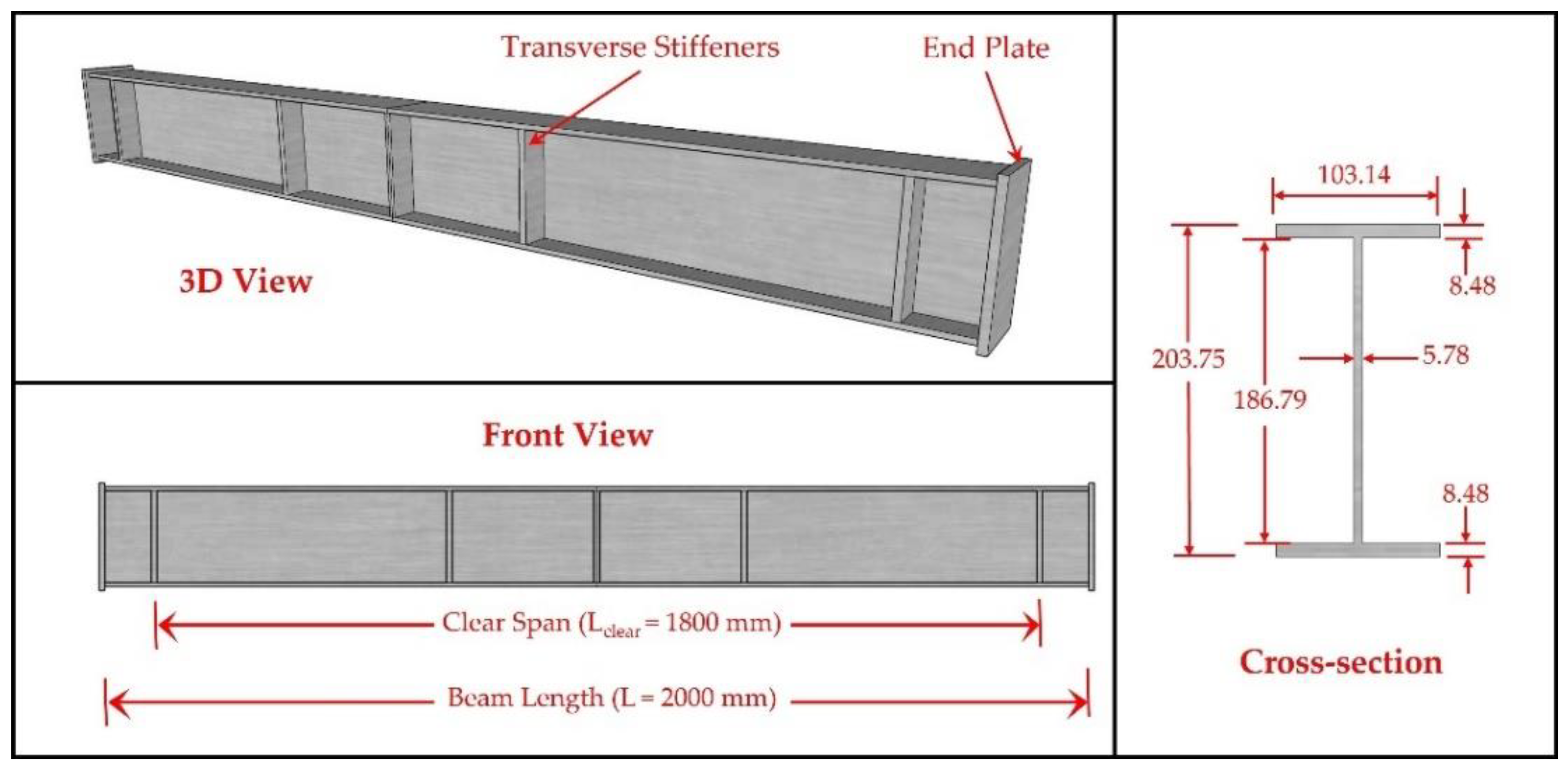
The experimental program investigated the flexural performance of steel beams strengthened by fastening HFRP strips using staggered steel bolts. The effect of spacing between bolts, HFRP length and thickness on the performance of the strengthened beams was investigated. The description of the various elements used and the test setup are outlined hereafter.

2.1. Steel Beams

Fourteen universal steel beams (UB 203 × 102 × 23) were incorporated into the test program. The tested beams had an overall length of 2000 mm and a clear span of 1800 mm with the distance from the end support to both end sections of the beam being 100 mm. Twelve-millimeter thick transverse stiffeners were welded at the loading points, at mid-span and at the supports to avoid premature local instability during testing. In addition, two end plates, 12 mm thick each, were welded to the beam ends. The dimensions of a typical control beam are shown in Figure 1. The mechanical properties of the steel beams were obtained by conducting uniaxial tensile testing of six steel coupons in accordance with ASTM−A370−21 standards [31]. Two coupons were cut from the web while the remaining four were cut from the flanges (two coupons from each flange). All tested steel coupons had a total length of 450 mm and a gauge length of 225 mm with a thickness that corresponds to either that of the web or the flange, as shown in Figure 2. Photos of a steel coupon during and after testing are displayed in Figure 3. The average tensile properties of the tested coupons showed a yield strength of 465 MPa, an ultimate strength of 620 MPa and an elastic modulus of 180 GPa.

2.2. HFRP Strips

The utilized hybrid carbon-glass fiber reinforced polymers (HFRP) were produced by STRONGWELL®, where two layers of fiberglass mats are bonded to enclosed carbon fibers using corrosion-resistant resin. The hybrid strips were supplied in rolls of 30 m length, 101.6 mm width and 3.175 mm thickness. The carbon fibers enhance the strength of the composite while the fiberglass augments its bearing properties. As reported by the manufacturer, the average tensile strength and tensile modulus of the HFRP are 852 MPa and 62.19 GPa, respectively [32].

2.3. Steel Bolts

The HFRP strips were fastened to the bottom flange of the steel beam using hexagonal galvanized zinc-coated M6 × 40 Hilti steel bolts where 6 is the bolt diameter in mm and 40 is the length of the threaded shank in mm, as depicted in Figure 4. The bolts are made of high tensile grade 8.8 steel according to DIN ISO 4017 standards [33] with 375 MPa shear strength and 1000 MPa bearing strength. Galvanized zinc-coated flat washers with a thickness of 2 mm, an inner diameter of 8.4 mm and an outer diameter of 28 mm were used in the study. The washers were firmly tightened to the steel bolts using 5 mm-thick hexagonal steel nuts.

2.4. Test Matrix and Methodology

Table 1 displays the test matrix for the tested beams. The designation of each specimen is denoted by the three main test parameters (HFRP length, HFRP thickness and spacing between bolts). The first component refers to the length of the HFRP strip to the nearest hundred. Three HFRP lengths (1620, 1170 and 810 mm) corresponding to 90, 65 and 45% of the clear span of the beam, respectively, were used. The second component in the designation implies the thickness of the HFRP strips; where “S” denotes a single strip with a thickness of 3.175 mm and “D” indicates double strips with 6.35 mm thickness. The last number in the designation indicates the spacing between bolts in millimeters rounded up to the nearest multiple of five. The effect of spacing between the staggered bolts was explored by considering three spacing values: 45, 100 and 150 mm. It should be noted that the reported spacing values represent the slanted distance between the bolts while maintaining a constant gauge distance of 15 mm between the bolts-lines, shown in Figure 5a. Six different strengthening configurations were examined experimentally with two replicates of each to ensure the repeatability and accuracy of the obtained results. Meanwhile, two unstrengthened control beams (CB) were tested to provide reference performance of the steel beams prior to strengthening.
Schematic views of strengthened UB 203 × 102 × 23 beams are displayed in Figure 5. All holes at the bottom steel flange were drilled using computerized automated CNC machines at a specialized steel manufacturing workshop. It is worth noting that all drilled holes had a typical standard diameter of 8 mm and rolled edge distances of 18 mm and 33 mm for the two gauge lines. The HFRP strips were cut to the required lengths and temporarily clamped to the bottom steel flange to mark the locations of the bolt holes using a dye. Holes with a typical diameter of 8 mm were drilled at the marked locations using an automated drill-bit. The drilling speed was kept at a minimum level to limit any possible damage to the HFRP strips around the holes. A minimum sheared edge distance of 50 mm was maintained in all HFRP strips, as recommended in an earlier study [22]. A dry towel and acetone solution were used to clean the beams and the HFRP strips from all sorts of dust and grease that accumulated during the fabrication and transportation processes. The HFRP strips were then placed on the bottom flange of the corresponding beam while maintaining proper alignment between the holes on the HFRP strip and their counterparts at the steel flange. The M6 steel bolts were used to fasten the HFRP strips to the bottom flange of the steel beams. Two washers per bolt were utilized to increase the bearing area at both sides of the connection, as recommended in [24]. Additionally, one M6 steel nut was utilized per bolt to tighten the assembly. A breaking torque wrench was set to 11 N.m and used to ensure the application of constant standard torque reflecting the full power of an ironworker, as recommended by AISC [34]. All beams and HFRP strips were stored in a dry clean area at room temperature in the structural laboratory. The strengthening scheme reported in this paper can be applied in the case of increase in the applied loads on a system of a concrete slab resting on the compression flange of a double symmetrical beam. In this case, fastening the HFRP strips to the tension flange of the beam would be a practical solution.

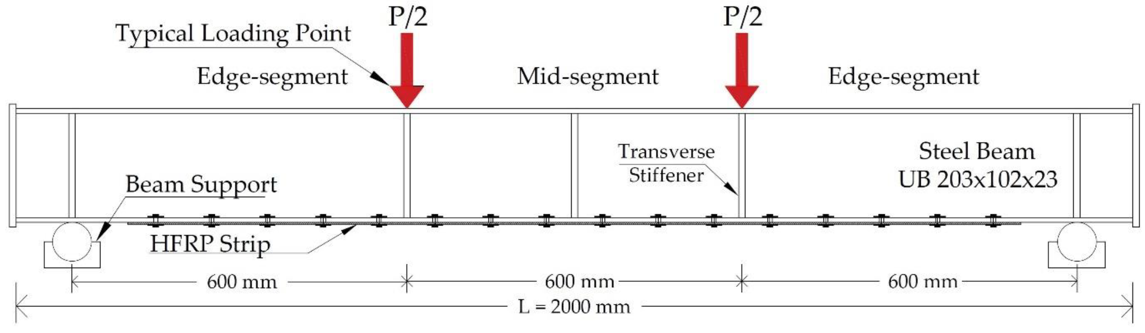
2.5. Test Setup and Instrumentation

All beams were tested in a four-point loading scheme to enable investigating the system behavior under pure flexure and combined shear–flexure stresses. Figure 6 simplifies the loading diagram adopted in the experimental study. The pure-moment zone between the two loading points is denoted as “mid-segment”, while the segments bound by one loading point and one vertical support are identified as “edge-segments”.
A schematic view and photo of the test setup are depicted in Figure 7. A 900 mm long built-up spreader beam was designed to transfer the load to the tested beams. The bottom flange of the spreader beam was welded to two rollers spaced 300 mm from the center of the spreader beam, resulting in a spacing of 600 mm between the two loading points (see Figure 7). Two pairs of lateral supports were used to enhance the stability of the spreader and to prevent its lateral movement during testing. Additionally, the inner surfaces of the lateral supports were lubricated with grease to ease the vertical sliding of the spreader during testing. The lateral supports were fixed to the strong floor of the structural laboratory. A steel loading column was designed and firmly fixed to the hydraulic actuator’s jack to transfer the stroke’s expansion to the other components of the test setup.
Electrical resistance strain gauges were mounted at various locations on the strengthened beams to enable capturing the strain distribution along the HFRP strips and across the beams’ cross-sections. All beams were instrumented with strain gauges at two sections (mid-segment and edge-segment) to monitor the generated strains under pure flexure and the combined shear–flexural effect. The HFRP strips were instrumented by electrical strain gauges along half the length of the strip. The number and locations of the mounted gauges varied according to the length of the HFRP strip and the spacing between bolts. The locations of the strain gauges on the tested beams are displayed in Figure 8. In order to obtain the experimental load–deflection curves and deflection profiles, all beams were instrumented with six linear variable displacement transducers (LVDTs) with a range of ±100 mm. Four LVDTs were placed along half the span of the beam (see Figure 8) to measure the vertical displacements and acquire the specimens’ deflection profiles at different loads. In addition, two more horizontal LVDTs were mounted perpendicular to the beam’s web to measure any out-of-plane deflection in case of lateral torsional buckling. The exact locations of the LVDTs are displayed on CB in Figure 8. It is worth mentioning that LVDT-1 at the mid-span was used to generate the load–deflection curve of each beam. Tests were conducted in a displacement-controlled manner with a rate of 1.5 mm/min to capture the post-peak response of the specimens. The load was applied using a 500 kN MTS hydraulic actuator. The applied loads were recorded by a 500 kN load cell which was placed between the loading column and the spreader beam (see Figure 7). All measuring devices were connected to a digital data logger that recorded the respective measurement per second. The accuracy of the recorded displacements and loads was up to 0.01 mm and 0.0001 kN, respectively.

3. Experimental Results and Discussions

The obtained experimental measurements are used to investigate and describe the flexural performance of all tested configurations. The yield and ultimate load capacities of the tested beams are reported in addition to the corresponding failure modes. The recorded strain measurements are used to analyze the strain distribution across the beam’s section and along the fastened HFRP strips at different loads. Discussions of the results and the associated characteristics are provided in the following subsections.

3.1. Failure Modes

Table 2 summarizes the experimental results of the tested configurations. The reported yield load (Py) and ultimate load (Pu) represent the average values of the replicates. All strengthened beams displayed better load carrying capacity than the unstrengthened control beam (CB), despite the possible minor weakness in the bottom flange due to the drilling process, with maximum improvements of 11.73 and 18.76% in the yield and ultimate loads, respectively. The two CB replicates experienced excessive lateral torsional buckling (LTB) deformations and major flange local buckling (FLB) after steel yielding (SY). In general, fastening the HFRP strips to the bottom steel flange delayed the onset of failure of all tested beams. The mechanism in which the fastening bolts transfer the stresses from the steel flange to the HFRP strip can be visualized by the bearing action between the bolts and HFRP displayed in Figure 9d. In addition to the bolt bearing (BB), the strengthened beams experienced excessive deflection and showed lateral torsional buckling (LTB) and local buckling deformations in the compression flange at high loads, as shown in Figure 9a–c, respectively. It is worth noting that HFRP sagging was observed following the unloading of 1620-S-150 and 810-S-100 beams, as presented in Figure 10. This observation implies the ability of the HFRP strips to elongate and contribute to the ductile behavior of the fastened system.

3.2. Load–Deflection Analyses and Discussions

3.2.1. Effect of Spacing between Bolts

The effect of changing the slanted spacing between the staggered bolts on the performance of the strengthened beams was assessed by comparing the experimental results of all specimens strengthened with a single 1620 mm-long HFRP strip (1620-S-45, 1620-S-100 and 1620-S-150). The load–deflection curves for all three configurations along with that of the control beam (CB) are plotted in Figure 11. The typical load–deflection curve of the tested beams can be characterized by three main zones: pre-yield elastic zone, transitional zone and post-yield inelastic zone. The elastic zone shows a linear load–deflection relation with a positive slope until the onset of yielding. At this point, the mid-span section, where LVDT-1 was placed, started to yield. The reduced slope in the transitional zone of the load–deflection curve (within a deflection range of 10 to 20 mm) reflects the propagation of yielding across the mid-span section until full yielding is reached. After that, the beams underwent inelastic deformations, where the additional loads caused considerably high deflections until the peak load is reached. Throughout the inelastic zone, yielding propagated along the beam span gradually, as implied by the small slope of the inelastic zone of the load–deflection curves. Figure 11 shows almost identical elastic behavior of the four configurations, while improved behavior of the three strengthened specimens with respect to the control beam CB can be noticed beyond the elastic zone. Beams 1620-S-150, 1620-S-100 and 1620-S-45 showed higher yield load than CB by 7.02, 8.50 and 10.49%, respectively. Additionally, ultimate load enhancement of 11.01, 14.22 and 16.53% was calculated for the three specimens, respectively, compared to the CB. As such, reducing the slanted spacing between the bolts from 150 to 100 mm and 45 mm resulted in a slight enhancement in the ultimate load carrying capacity of the system by 2.9 and 5%, respectively. Reducing the spacing between the bolts enabled the use of more steel bolts to fasten the 1620 mm long HFRP strip to the tension flange. The increased number of bolts allowed for more efficient load transfer from the beam to the HFRP strip, resulting in higher load carrying capacity of beams with less spacing between bolts.
The deflection profiles along half the span of 1620-S-45, 1620-S-100 and 1620-S-150 specimens at a load of 380 kN are shown in Figure 12. This specific load value is selected, as it is slightly less than the peak load of all specimens, which allows for assessing the impact of the strengthening configurations on the serviceability of the system. It can be seen from the figure that decreasing the spacing between bolts reduced the deflection of the strengthened beam indicating better serviceability of the strengthened system. Reducing the spacing from 150 to 100 mm and 45 mm decreased the mid-span deflection at 380 kN by 9.5 and 15.5%, respectively, compared to the configuration of 150 mm spacing. The increased number of fastening bolts associated with reducing the spacing between bolts enabled for more contribution of the HFRP strips to the stiffness of the system, especially in the post-yield inelastic stage, where the stiffness of the steel section is significantly reduced.

3.2.2. Effect of HFRP Length

The load–deflection curves for beams 810-S-100, 1170-S-100 and 1620-S-100 that are strengthened by various lengths of single HFRP strips are presented in Figure 13. In all specimens, HFRP is fastened to the steel section using staggered steel bolts spaced at 100 mm. The plots reveal the performance improvement associated with increasing the length of the HFRP. Beams 810-S-100, 1170-S-100 and 1620-S-100 showed 5.22, 7.54 and 8.5% enhancements in the yield load compared to CB, respectively. Additionally, the estimated improvement in the ultimate loads of 810-S-100, 1170-S-100 and 1620-S-100 compared to CB is 8.5, 10.59 and 14.22%, respectively. The increased HFRP length allowed for using more steel bolts, which consequently facilitated the load transfer to the fastened HFRP strip. As a result, higher ultimate load carrying capacities are enabled for beams strengthened with longer FRP strips. For instance, increasing the length of a single HFRP strip from 810 to 1620 mm resulted in relative improvement in the yield and ultimate capacities of the strengthened beams by 3.12 and 5.27%, respectively. This implies insignificant improvement in the load carrying capacity despite doubling the length of HFRP strips. On the contrary, this increase in the length of the HFRP strip resulted in a significant enhancement in the serviceability of the strengthened beams, as indicated by the 30% reduction in the mid-span deflection at a load of 380 kN, shown by the deflection profiles of 810-S-100, 1170-S-100 and 1620-S-100 specimens displayed in Figure 14. The reduced deflection associated with the increased length of the HFRP strip can be attributed to the enhanced stiffness of the beam due to the increased number of fastening bolts used with a long HFRP strip. As alluded to in the previous section, this effect is more remarkable in the post-yield stage when the stiffness of the steel beam is reduced drastically.

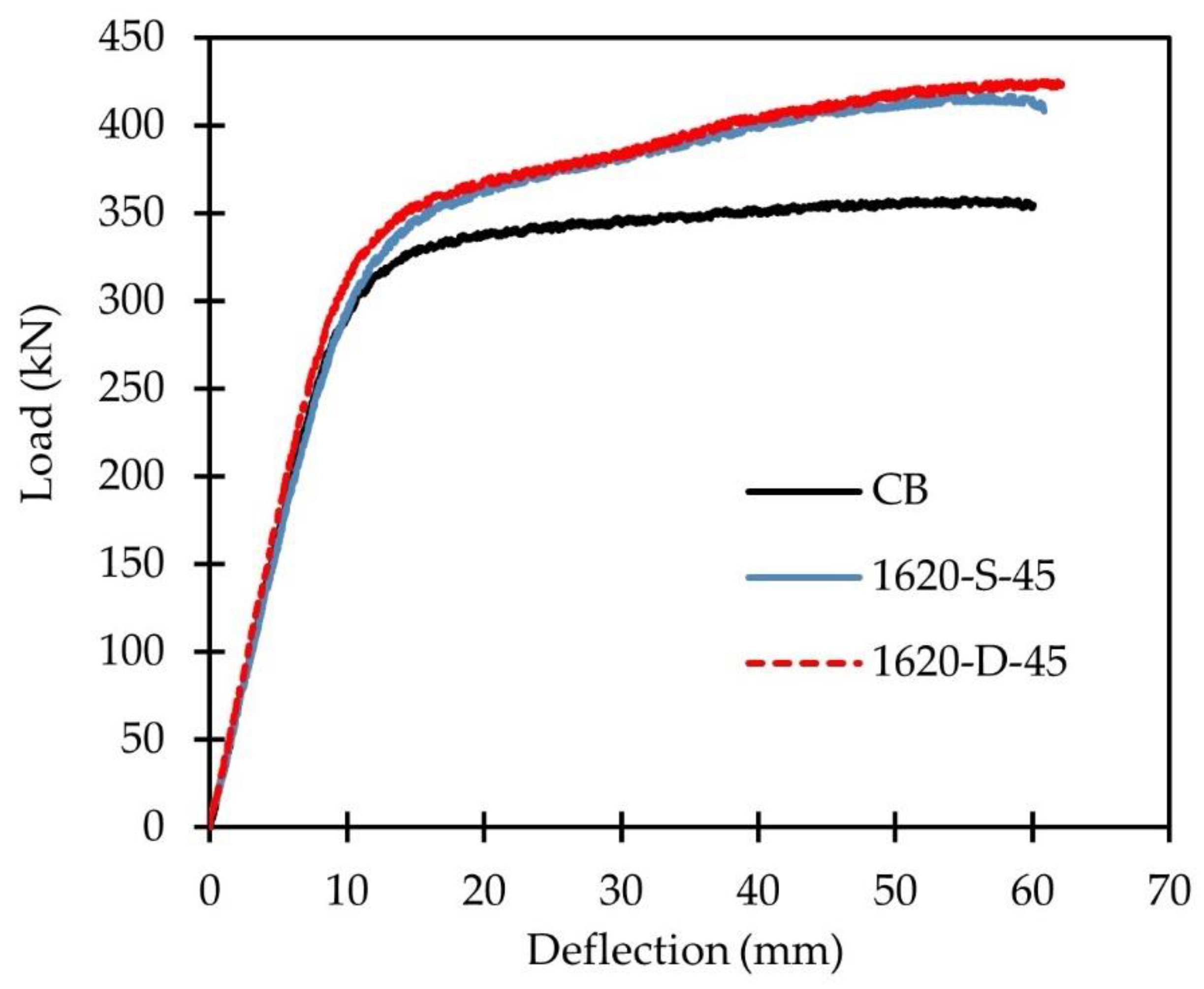
3.2.3. Effect of HFRP Thickness

The effect of changing the thickness of the fastened HFRP strip is assessed by comparing the performance of the 1620-S-45 and 1620-D-45 specimens where HFRP with 3.175 and 6.35 mm thickness, respectively, were used. Both specimens have the same HFRP length (1620 mm) and spacing between bolts (45 mm). The load–deflection curves shown in Figure 15 imply that the ultimate capacity of the 1620-D-45 specimen with two HFRP strips was 1.92% higher than that of the 1620-S-45 specimen with a single strip. This implies that doubling the thickness of the HFRP while keeping identical fastening conditions has an insignificant impact on the load carrying capacity of the strengthened beam; however, it increases the cost of the strengthening system. Although doubling the thickness of the HFRP leads to higher bearing strength of the bolts, no remarkable increase in the load carrying capacity was attained as the failure of the system was not controlled by bolt-bearing, and yet was governed by flange local buckling and lateral torsional buckling of the beam, which took place before full utilization of the additional HFRP thickness. Additionally, using double HFRP strips resulted in a considerable increase in the stiffness of the system compared to the single strip configuration, resulting in a 27.31% reduction in the mid-span deflection, as depicted in Figure 16.

3.3. Strain Profiles and Analysis

3.3.1. Analysis of Composite Action

In order to investigate the relative performance of the tested configurations, strain variations across the depth of the beam section and along the HFRP strips are discussed in this section. Figure 17 compares the induced strains at the mid-segment of specimen 1620-S-45 to those induced in CB at 250 kN (pre-yielding) and at 310 kN (post-yielding). Strain reductions of 17.11 and 23.10%, respectively, were calculated at the inner face of the bottom flange at the mid-segment section (i.e., SG5). This reflects a more pronounced contribution of the fastened HFRP strips in resisting the applied loads in the post-yielding zone. Figure 18a shows the tensile strains in the mid-segment of beam 1620-S-45. The large number of the fastening bolts in this specimen provided high bearing between the fastened components, as evidenced by the linear distribution of the tensile strains at the HFRP-steel interface before yielding (load values of 150, 200 and 250 kN). After yielding, the effective steel modulus (Eeff) declines significantly to about 1.5% of its elastic modulus (Es) [35]. At this loading stage, the modulus of the fastened HFRP strip (62.19 GPa) is about 23 times higher than the effective steel modulus Eeff (2.7 GPa). Thus, the compatibility of the fastened section decreased slightly causing an abrupt change in the strain at the steel-HFRP interface, as shown in Figure 18a. Higher strains were recorded in the HFRP compared to those in the yielded steel flange at a load of 310 kN (Figure 18a). This finding coincides with the reported outcomes for bonded FRP-steel beams [36,37,38]. Reducing the number of the fastening bolts by using larger spacing values adversely influenced the composite action, as observed by comparing the tensile strains at the mid-segments of 1620-S-45, 1620-S-100 and 1620-S-150 in Figure 18a–c, respectively. Although the tensile strains of beams 1620-S-45 and 1620-S-100 at the mid-segment showed linear distribution before yielding, lower HFRP strains were recorded in 1620-S-150 at early loading stages due to the high bearing stresses at the bolt holes, which weakened the HFRP at early stages. It is worth noting that beam 1620-S-150 had one-third the number of bolts in beam 1620-S-45. The reduced number of the fastening bolts in beam 1620-S-150 resulted in high-stress concentrations around the bolt holes causing early bearing damage in the HFRP strip. The deterioration of the HFRP at the bolt holes caused lower HFRP strains than those at the bottom steel flange, as shown in Figure 18c. In that case, the strains on the bottom steel flange increased at a faster rate than the HFRP strains due to the continuous deterioration of the HFRP strip. It is important to highlight that similar behavior of the strain distribution (i.e., lower FRP strains than steel strains) was reported in earlier research on bonded FRP-steel beams after de-bonding failure [38,39]. Wu et al. [40] and Kamruzzaman [41] referred the lower strains on the CFRP to the shear-lag phenomena, which has a similar effect to the high bearing stresses in the bolted systems.
Sample analysis of strain variation in 1170-S-100 specimen is carried out in view of the strain profiles in two sections at the mid-segment and edge-segment, which are shown in Figure 19a,b, respectively. Almost linear strain distribution can be observed in the mid-segment section before yielding (load of 250 kN). This trend was altered after yielding due to the lateral, torsional and local deformations of the beam and the contribution of the fastened HFRP strip. For example, at a load value of 355 kN, SG2 displayed higher strains than SG1 due to the additional compression stresses exerted on the front–inner face of the top flange due to the lateral buckling of the beam. At any load level, the compression strains experienced by the mid-segment section were higher than their counterparts at the edge-segment section. For example, at a load value of 340 kN, strains at SG2 were 33.20% higher than those at SG7. Meanwhile, the tensile strains at the bottom steel flange (i.e., SG5 and SG10) were in the range 1740–1780 με in both segments at the same load. This observation indicates the effectiveness of the fastened HFRP in reducing the steel tensile stresses at both segments. Figure 19a provides a better understanding of the shared stresses between the two fastened elements (i.e., bottom steel flange and HFRP strip) by analyzing the measurements of (SG5) and (SG12), respectively. In the pre-yield zone, both steel and HFRP experienced almost equal strains reflecting full composite action. This is based on the fact that the composite action is reflected by the amount of strain compatibility between the steel section and HFRP, which indicates their ability to act together in resisting the applied loads. As the load exceeded 250 kN, relative slippage started to take place due to the progressive micro-damage around the bolt holes caused by the bearing action between the bolts and HFRP strips. As a result, higher steel strains (SG5) than HFRP strains (SG12) can be noticed. Similar behavior can be observed in the edge-segment except that the strain variations at the compression side due to the flange local buckling are minimal (see Figure 19b). Plotted strains at the edge-segment of 1170-S-100 in Figure 19b show weaker composite action than that in the mid-segment. This is evident by the early relative slippage due to the effect of shear stresses, which leads to higher bearing stresses near the HFRP edge.
Comparing the tensile strains of 1620-S-100 at the mid-segment and the edge-segment in Figure 20 indicates a lower level of composite action at the edge-segment. This implies higher stress concentrations near the HFRP edge, reflecting a similar behavior to the de-bonding process that typically initiates at the FRP edge in bonded FRP-steel beams, as reported in earlier studies [16,38,40,42,43]. Reducing the number of the fastening bolts by decreasing the length of the HFRP strip had a negative effect on the level of composite action of the fastened components, as shown by comparing the tensile strains of 1620-S-100, 1170-S-100 and 810-S-100 in Figure 21. Linear strain distributions were plotted at the mid-segments of 1620-S-100 and 1170-S-100 before steel yielding. Although the HFRP strains of 1620-S-100 after yielding were higher than the steel strains, lower HFRP strains were recorded on beam 1170-S-100 due to the reduced HFRP length. Further reduction in the HFRP length resulted in an early loss in the composite action of the fastened materials, as evidenced by the lower HFRP strains at a load of 150 kN in beam 810-S-100 (refer to Figure 21c). Thus, the distribution of the tensile strains over the cross-section of the strengthened beams highlights three main trends. Linear strain distribution with full composite action was attained before yielding by utilizing a proper number of bolts that enables full compatibility at the steel-HFRP interface. A bi-linear strain distribution with higher HFRP strains was reported after steel yielding in configurations with a proper number of bolts. Finally, a bi-linear strain distribution with higher steel strains was attained before and after yielding when the HFRP experienced high concentrations of the bearing stresses.
The strain gauges mounted along the HFRP strips were used to assess the distribution of the flexural strains in the fastened strips. Sample strain distribution along the HFRP strip of 1170-S-100 at different loads is plotted in Figure 22. It should be noted that strain gauges were used to instrument only the half-span of the tested beams. Nevertheless, due to the symmetry in beam geometry and loading conditions, recorded strains in (SG11) to (SG17) were mirrored around the beam centerline for a more meaningful presentation. Plotted flexural strains at various load levels followed a similar trend of the bending moment distribution in a simply supported beam subjected to four-point loading. This observation is in agreement with earlier reported results of numerical and experimental investigations for the behavior of bonded steel-FRP beams [44,45,46]. It is worth mentioning that El Damatty et al. [36] reported that the strain distribution followed the moment distribution only in the post-yield zone when the load was mainly carried by the FRP in bonded FRP-steel beams. In the current study, this typical distribution is shown both in the pre- and post-yield zones, which implies the effectiveness of the fastened system in sharing the loads between steel and HFRP from early loading stages.

3.3.2. Effect of Spacing between Bolts

The strain profiles at the mid-segment and edge-segment section of 1620-S-45, 1620-S-100, 1620-S-150 and CB specimens at a load value of 310 kN are presented in Figure 23a,b, respectively. The plots indicate that using fastened HFRP strips reduced the strains at the tension side of the beam section in both segments compared to CB. The difference between the tensile strains in the HFRP strips and those in the steel flange is attributed to the relative slippage between both elements. Reducing the spacing between the staggered bolts remarkably enhanced the composite action of the section, as evident by the no-slippage in both segments of the 1620-S-45 specimen at 310 kN. Specimen 1620-S-100 underwent slippage at the edge-segment only. Meanwhile, specimen 1620-S-150 experienced slippage at both segments at 310 kN, as reflected by the calculated strain differences of 710 and 920 με at the mid-segment and edge-segment, respectively. The distribution of the flexural strains along the span of the fastened HFRP strips in the three specimens 1620-S-45, 1620-S-100 and 1620-S-150 at a load of 380 kN is displayed in Figure 24. The plot shows that reducing the spacing between the staggered bolts enhanced the contribution of the fastened HFRP in resisting the applied loads. Higher strain measurements were recorded along the span of 1620-S-45 compared to 1620-S-100 and 1620-S-150 at the same sections located at any distance from the beam’s centerline.

3.3.3. Effect of HFRP Length

Assessing the impact of HFRP length on the performance is presented by comparing the strain variations in 1620-S-100, 1170-S-100 and 810-S-100 specimens in which HFRP thickness and spacing between bolts are kept unchanged. The strain profiles at the mid-segment and edge-segment of the three specimens and CB at 310 kN are depicted in Figure 25a,b, respectively. Better composite action can be observed in 1620-S-100 compared to 1170-S-100 and 810-S-100. The slippage at the steel-HFRP interface in the mid-segment of 810-S-100 was triple that of the 1170-S-100 specimen, which highlights the significant effect of HFRP length, and consequently the number of fastening bolts, on the composite section. It can be noticed from Figure 25 that the effectiveness of the fastened HFRP strips in reducing the steel tensile strains was more pronounced in the mid-segment than in the edge-segment. This could be attributed to the combined shear–flexure effect in the edge-segment, as opposed to the pure flexural effect in the mid-segment.
The strain distribution along the HFRP strip of the three specimens 1620-S-100, 1170-S-100 and 810-S-100 at 380 kN is presented in Figure 26. The utilization of long HFRP in 1620-S-100 resulted in a better contribution toward resisting the applied loads, as evidenced by the higher strain measurements recorded in the HFRP strip of 1620-S-100 specimen compared to the 1170-S-100 and 810-S-100 specimens at any load value.

3.3.4. Effect of HFRP Thickness

Figure 27 displays the strain profiles at the mid-segment sections of 1620-S-45 and 1620-D-45 specimens at a load of 310 kN. Both beams are strengthened with 1620 mm long HFRP strips using bolts spaced at 45 mm. The tensile strains at the mid-segment of 1620-S-45 showed close values to those measured in 1620-D-45. This observation highlights the insignificant effect of doubling the thickness of HFRP strips (1620-D-45) on the strain compatibility of the fastened components. This could be attributed to the fact that bearing was not the dominating failure mode for all tested specimens; therefore, increasing the bearing strength would not result in a remarkable improvement in the performance of strengthened beams.

4. Conclusions

This study investigated the flexural performance of steel beams strengthened by fastening HFRP strips using staggered steel bolts. The effects of the spacing between bolts, HFRP length and thickness were investigated by testing fourteen UB203 ×102 ×23 steel beams in a four-point loading setup. The performance of the examined configurations was evaluated by analyzing the governing failure modes, load–deflection relations and strain profiles and variations. An extensive discussion of the composite action between the fastened materials was conducted using the measured strains. The main conclusions of the conducted experimental investigations are outlined herein:
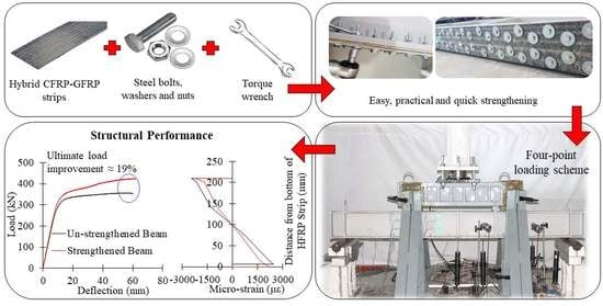
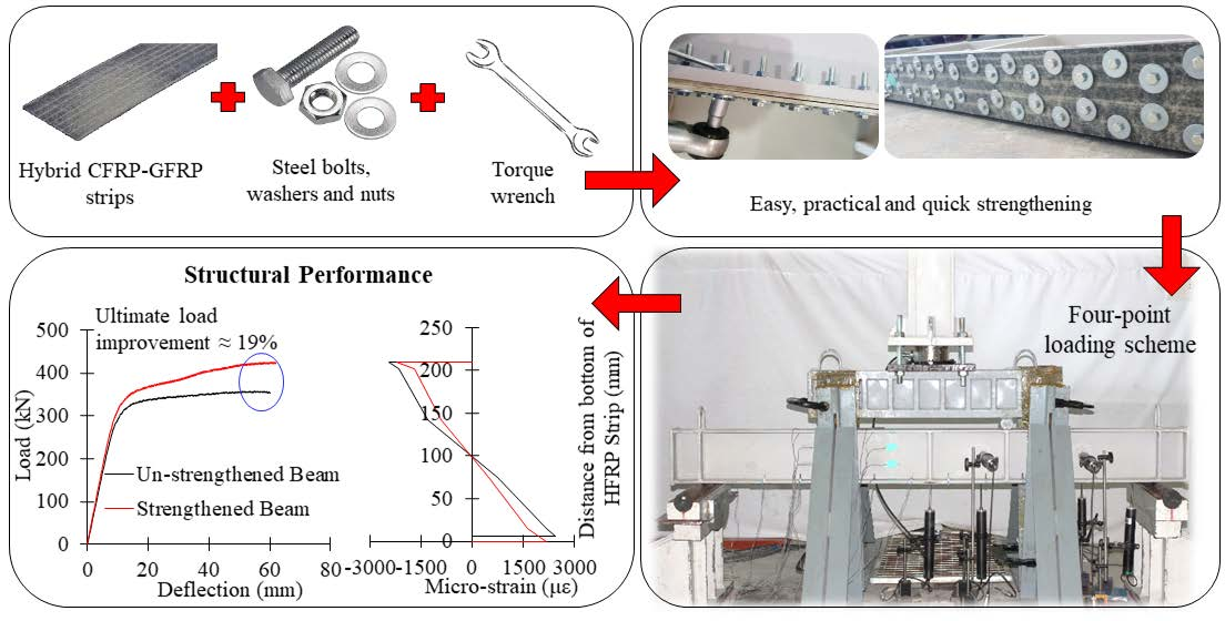
  • Strengthening the steel beams by fastening HFRP strips at the tension flange using M6 steel bolts in staggered arrangements showed considerable enhancements in the yield and ultimate load capacities relative to the unstrengthened control beams (CB). This is reflected by yield load increase ranging from 5.22 to 11.73% and ultimate load improvement from 8.50 to 18.76%.
  • All strengthened beams failed in a ductile manner after experiencing a combination of failure mechanisms including steel yielding, bearing between the fastening bolts and the HFRP strip, local buckling in the compression flange and lateral torsional buckling.
  • Reducing the slanted spacing between the staggered bolts from 150 to 45 mm resulted in additional enhancement in the ultimate load carrying capacity of the system by 5% and enhanced the serviceability of the system, as evidenced by the 15.5% reduction in the mid-span deflection calculated at load 380 kN.
  • Doubling the length of a single HFRP strip fastened by staggered steel bolts showed a 30% reduction in the mid-span deflection at 380 kN, indicating a remarkable enhancement in the serviceability. Meanwhile, doubling the HFRP length resulted in relative improvement in the yield and ultimate capacities of the strengthened beams by 3.12 and 5.27%, respectively.
  • Doubling the thickness of the HFRP while utilizing a length that is 90% of the beam clear span increases the cost of the strengthening system with an insignificant effect on the load carrying capacity and composite action of the beam.
  • The flexural strains along the length of the fastened HFRP strips followed a similar trend to the profile of the bending-moment diagram of a simply supported beam subjected to four-point loading. The strain distribution showed a relatively steep increasing slope from the edge of the HFRP strip to the loading points, followed by almost steady strains with minor variations.
  • Better strain compatibility and less interfacial slippage between the bottom steel flange and the fastened HFRP are attained by reducing the spacing between bolts and utilizing long HFRP strips.
  • The composite action between the fastened HFRP-steel beams is influenced by the bearing stresses between the bolts and HFRP, and the elastic modulus of the steel beams relative to that of the HFRP strips.
  • The distribution of the tensile strains over the cross-section of the strengthened beams highlighted three main trends. Linear strain distribution with full composite action before yielding while utilizing a proper number of bolts. A bi-linear strain distribution with higher HFRP strains after steel yielding in configurations with a proper number of bolts. Finally, a bi-linear strain distribution with higher steel strains before and after yielding when the HFRP experienced high bearing stresses.
It should be highlighted that the findings of this study are limited to the size and properties of the utilized steel bolts and HFRP strips. The results pertain to bolt spacing that ranges from 45 to 150 mm for M6 × 40 Hilti steel bolts with the pre-defined specifications. In addition, the reported enhancements in the beams’ strength are associated with using the described hybrid carbon-glass FRP provided by STRONGWELL® considering 3.175 and 6.35 mm thicknesses. The behavior of the strengthened beams beyond the termination deflection (i.e., 60 mm) was not predicted as the applied load on the specimens almost reached the maximum capacity of the hydraulic actuator, risking the stability of the test setup and the safety of the personnel.

Author Contributions

Conceptualization, A.M.I.S. and O.R.A.-H.; methodology, A.M.I.S. and O.R.A.-H.; investigation, O.R.A.-H. and A.M.I.S.; validation, O.R.A.-H. and A.M.I.S.; formal analysis, O.R.A.-H. and A.M.I.S.; resources, A.M.I.S.; data curation, O.R.A.-H.; writing—original draft preparation, O.R.A.-H.; writing—review and editing, A.M.I.S. and B.E.-A.; visualization, O.R.A.-H. and A.M.I.S.; supervision, A.M.I.S. and B.E.-A.; project administration, A.M.I.S.; funding acquisition, A.M.I.S. All authors have read and agreed to the published version of the manuscript.

Funding

This research is funded by the Emirates Center for Mobility Research (ECMR) at UAE University, grant number 31R083.

Institutional Review Board Statement

Not applicable.

Informed Consent Statement

Not applicable.

Data Availability Statement

The data presented in this study are available on request from the corresponding author.

Acknowledgments

The authors would like to acknowledge the technical support provided by Tarek Salah, the senior laboratory specialist in the Structures Laboratory at UAE University.

Conflicts of Interest

The authors declare no conflict of interest.

References

  1. Federal Highway Administration. Archived: Deficient Bridges by Superstructure Material. 2016. Available online: https://www.fhwa.dot.gov/bridge/nbi/no10/mat16.cfm (accessed on 26 October 2022).
  2. Yu, Y.; Chiew, S.P.; Lee, C.K. Bond failure of steel beams strengthened with FRP laminates–Part 2: Verification. Compos. Part B Eng. 2011, 42, 1122–1134. [Google Scholar] [CrossRef]
  3. Narmashiri, K.; Sulong, N.R.; Jumaat, M.Z. Failure analysis and structural behaviour of CFRP strengthened steel I-beams. Constr. Build. Mater. 2012, 30, 1–9. [Google Scholar] [CrossRef]
  4. Borrie, D.; Al-Saadi, S.; Zhao, X.L.; Raman, R.K.; Bai, Y. Bonded CFRP/steel systems, remedies of bond degradation and behaviour of CFRP repaired steel: An overview. Polymers 2021, 13, 1533. [Google Scholar] [CrossRef] [PubMed]
  5. Al-Ridha, A.S.; Hameed, Q.K.; Atshan, A.F.; Abbood, A.A.; Dheyab, L.S. Evaluation of strengthening steel beams using the technique of carbon fiber confinement by a steel plate (CFCSP). Adv. Civ. Eng. Mater. 2020, 9, 53–66. [Google Scholar] [CrossRef]
  6. Pang, Y.; Wu, G.; Wang, H.; Su, Z.; He, X. Experimental study on the bond behavior of CFRP-steel interfaces under quasi-static cyclic loading. Thin-Walled Struct. 2019, 140, 426–437. [Google Scholar] [CrossRef]
  7. Batuwitage, C.; Fawzia, S.; Thambiratnam, D.; Al-Mahaidi, R. Evaluation of bond properties of degraded CFRP-strengthened double strap joints. Compos. Struct. 2017, 173, 144–155. [Google Scholar] [CrossRef] [Green Version]
  8. Yang, Y.; Biscaia, H.; Chastre, C.; Silva, M.A. Bond characteristics of CFRP-to-steel joints. J. Constr. Steel Res. 2017, 138, 401–419. [Google Scholar] [CrossRef]
  9. Chataigner, S.; Benzarti, K.; Foret, G.; Caron, J.F.; Gemignani, G.; Brugiolo, M.; Calderon, I.; Piñero, I.; Birtel, V.; Lehmann, F. Design and testing of an adhesively bonded CFRP strengthening system for steel structures. Eng. Struct. 2018, 177, 556–565. [Google Scholar] [CrossRef]
  10. Yang, Y.; Silva, M.A.; Biscaia, H.; Chastre, C. CFRP-to-steel bonded joints subjected to cyclic loading: An experimental study. Compos. Part B Eng. 2018, 146, 28–41. [Google Scholar] [CrossRef]
  11. Hu, L.; Feng, P.; Zhao, X.L. Fatigue design of CFRP strengthened steel members. Thin-Walled Struct. 2017, 119, 482–498. [Google Scholar] [CrossRef]
  12. Heshmati, M.; Haghani, R.; Al-Emrani, M. Durability of bonded FRP-to-steel joints: Effects of moisture, de-icing salt solution, temperature and FRP type. Compos. Part B Eng. 2017, 119, 153–167. [Google Scholar] [CrossRef] [Green Version]
  13. Heshmati, M.; Haghani, R.; Al-Emrani, M. Durability of CFRP/steel joints under cyclic wet-dry and freeze-thaw conditions. Compos. Part B Eng. 2017, 126, 211–226. [Google Scholar] [CrossRef]
  14. Deng, J.; Li, J.; Zhu, M. Fatigue behavior of notched steel beams strengthened by a prestressed CFRP plate subjected to wetting/drying cycles. Compos. Part B Eng. 2022, 230, 109491. [Google Scholar] [CrossRef]
  15. Yang, Y.; Zhao, J.; Zhang, S.; Chastre, C.; Biscaia, H. Effect of mechanical anchorage on the bond performance of double overlapped CFRP-to-steel joints. Compos. Struct. 2021, 267, 113902. [Google Scholar] [CrossRef]
  16. Siwowski, T.W.; Siwowska, P. Experimental study on CFRP-strengthened steel beams. Compos. Part B Eng. 2018, 149, 12–21. [Google Scholar] [CrossRef]
  17. Katrizadeh, E.; Narmashiri, K. Experimental study on failure modes of MF-CFRP strengthened steel beams. J. Constr. Steel Res. 2019, 158, 120–129. [Google Scholar] [CrossRef]
  18. Kumaraguru, S.; Alagusundaramoorthy, P. Flexural strengthening of steel beams using pultruded CFRP composite sheets with anchorage mechanisms. Structures 2021, 33, 1414–1427. [Google Scholar] [CrossRef]
  19. Esmaeeli, E.; Shadan, P. Effectiveness of Fan Anchors in Preventing Debonding in FRP-Strengthened Steel Members. Int. J. Steel Struct. 2022, 1–24. [Google Scholar] [CrossRef]
  20. Bagale, B.R.; Parvin, A. Fiber-Reinforced Polymer Strengthening of Steel Beams under Static and Fatigue Loadings. Pract. Period. Struct. Des. Constr. 2021, 26, 04020046. [Google Scholar] [CrossRef]
  21. Hai, N.D.; Mutsuyoshi, H. Structural behaviour of double-lap joints of steel splice plates bolted/bonded to pultruded hybrid CFRP/GFRP laminates. Constr. Build. Mater. 2012, 30, 347–359. [Google Scholar] [CrossRef]
  22. Sweedan, A.M.I.; El-Sawy, K.M.; Alhadid, M.M. Interfacial behaviour of mechanically anchored FRP laminates for strengthening steel beams. J. Constr. Steel Res. 2013, 80, 332–345. [Google Scholar] [CrossRef]
  23. El-Sisi, A.E.D.; Sallam, H.E.D.; Salim, H.A.; El-Husseiny, O.M. Structural behaviour of hybrid CFRP/steel bolted staggered joints. Constr. Build. Mater. 2018, 190, 1192–1207. [Google Scholar] [CrossRef]
  24. Abou El-Hamd, O.R.; Sweedan, A.M.I.; El-Sawy, K.M. Experimental and numerical study of the parameters controlling the behaviour of double-lap connections of steel plates bolted to hybrid FRP strips. Thin-Walled Struct. 2018, 125, 140–151. [Google Scholar] [CrossRef]
  25. Jiang, Z.; Wan, S.; Fang, Z.; Song, A. Static and fatigue behaviours of a bolted GFRP/steel double lap joint. Thin-Walled Struct. 2021, 158, 107170. [Google Scholar] [CrossRef]
  26. Sweedan, A.M.I.; Alhadid, M.M.; El-Sawy, K.M. Experimental study of the flexural response of steel beams strengthened with anchored hybrid composites. Thin-Walled Struct. 2016, 99, 1–11. [Google Scholar] [CrossRef]
  27. Sweedan, A.M.I.; Rojob, H.N.; El-Sawy, K.M. Mechanically-fastened hybrid composites for flexural strengthening of steel beams. Thin-Walled Struct. 2014, 85, 250–261. [Google Scholar] [CrossRef]
  28. Sweedan, A.M.I.; Rojob, H.N.; El-Sawy, K.M. Analytical and numerical study of the serviceability performance of partial composite steel-FRP beams. Int. J. Struct. Integr. 2018, 9, 625–645. [Google Scholar] [CrossRef]
  29. Cadei, J.C.; Stratford, T.J.; Duckett, W.G.; Hollaway, L.C. Strengthening Metallic Structures Using Externally Bonded Fibre-Reinforced Polymers; Ciria: London, UK, 2004. [Google Scholar]
  30. Selvaraj, S.; Madhavan, M. Design of steel beams strengthened with low-modulus CFRP laminates. J. Compos. Constr. 2020, 24, 04019052. [Google Scholar] [CrossRef]
  31. ASTM A370-21; Standard Test Methods and Definitions for Mechanical Testing of Steel Products. ASTM International: West Conshohocken, PA, USA, 2021.
  32. Strongwell Manufacturing Plants. SAFSTRIP: Fiber Reinforced Strengthening Strip; Strongwell Manufacturing Plants: Chatfield, MN, USA, 2020. [Google Scholar]
  33. DIN EN ISO 4017; Fasteners—Hexagon Head Screws—Product Grades A and B. DIN Standards, DIN-Adopted European-Adopted ISO Standards. Beuth Publishing DIN: Berlin, German, 2014.
  34. ANSI/AISC 370–21; Specification for Structural Stainless Steel Buildings. 1st ed. American Institute of Steel Construction (AISC): Chicago, IL, USA, 2021.
  35. Foster, A.S.J.; Gardner, L.; Wang, Y. Practical strain-hardening material properties for use in deformation-based structural steel design. Thin-Walled Struct. 2015, 92, 115–129. [Google Scholar] [CrossRef]
  36. El Damatty, A.A.; Abushagur, M.; Youssef, M.A. Experimental and analytical investigation of steel beams rehabilitated using GFRP sheets. Steel Compos. Struct. 2003, 3, 421–438. [Google Scholar] [CrossRef]
  37. Lenwari, A.; Thepchatri, T.; Albrecht, P. Flexural response of steel beams strengthened with partial-length CFRP plates. J. Compos. Constr. 2005, 9, 296–303. [Google Scholar] [CrossRef]
  38. Sen, R.; Liby, L.; Mullins, G. Strengthening steel bridge sections using CFRP laminates. Compos. Part B Eng. 2001, 32, 309–322. [Google Scholar] [CrossRef]
  39. Deng, J.; Jia, Y.; Zheng, H. Theoretical and experimental study on notched steel beams strengthened with CFRP plate. Compos. Struct. 2016, 136, 450–459. [Google Scholar] [CrossRef]
  40. Wu, G.; Wang, H.T.; Wu, Z.S.; Liu, H.Y.; Ren, Y. Experimental study on the fatigue behavior of steel beams strengthened with different fiber-reinforced composite plates. J. Compos. Constr. 2012, 16, 127–137. [Google Scholar] [CrossRef]
  41. Kamruzzaman, M. Mitigation of Plate end Debonding in CFRP Strengthened Wide-Flange Steel I-Beams under Monotonic and Fatigue Loading. Doctoral Dissertation, University of Malaya, Kuala Lumpur, Malaysia, 2017. [Google Scholar]
  42. Al- Ridha, A.S.; Atshan, A.F.; Mahmoud, K.S.; Hameed, Q.K. Effect of strengthening of steel beams with variable length by using carbon fiber. J. Eng. 2019, 2019, 1631692. [Google Scholar] [CrossRef] [Green Version]
  43. Deng, J.; Lee, M.M. Behaviour under static loading of metallic beams reinforced with a bonded CFRP plate. Compos. Struct. 2007, 78, 232–242. [Google Scholar] [CrossRef]
  44. Youssef, M.A. Analytical prediction of the linear and nonlinear behaviour of steel beams rehabilitated using FRP sheets. Eng. Struct. 2006, 28, 903–911. [Google Scholar] [CrossRef]
  45. Kamruzzaman, M.; Jumaat, M.Z.; Sulong, N.H.R.; Qeshta, I.M.I.; Narmashiri, K. Effects of lateral bracing and stiffeners on the CFRP failure of strengthened steel beams. IOP Conf. Ser. Mater. Sci. Eng. 2017, 210, 012021. [Google Scholar] [CrossRef] [Green Version]
  46. Peiris, A.; Harik, I. Steel beam strengthening with UHM CFRP strip panels. Eng. Struct. 2021, 226, 111395. [Google Scholar] [CrossRef]
Figure 1. Schematic views and dimensions of the control beam (dimensions are in mm).
Buildings 12 02150 g001
Figure 2. Geometry and dimensions of steel coupons (dimensions are in mm).
Buildings 12 02150 g002
Figure 3. Photos of a typical steel coupon: (a) during testing; (b) after testing.
Buildings 12 02150 g003
Figure 4. (a) Photo of the M6 × 40 steel bolt; (b) sketch and dimensions of the utilized steel bolt (dimensions are in mm).
Buildings 12 02150 g004
Figure 5. Schematic views of: (a) 1620-S-100 beam; (b) 1620-D-45 beam.
Buildings 12 02150 g005
Figure 6. Simplified loading diagram of the tested beams.
Buildings 12 02150 g006
Figure 7. (a) Schematic of the test setup (dimensions in mm); (b) photo of the test setup.
Buildings 12 02150 g007aBuildings 12 02150 g007b
Figure 8. Instrumentation of the tested beams.
Buildings 12 02150 g008aBuildings 12 02150 g008b
Figure 9. Sample photos of the observed failure modes of the strengthened beams: (a) excessive deflection; (b) lateral torsional buckling; (c) flange local buckling; (d) bolt bearing against the HFRP strip.
Buildings 12 02150 g009
Figure 10. Sagging of the HFRP strip in 1620-S-150 beam.
Buildings 12 02150 g010
Figure 11. Load–deflection curves of 1620-S-45, 1620-S-100, 1620-S-150 and CB.
Buildings 12 02150 g011
Figure 12. Deflection profiles along the spans of 1620-S-45, 1620-S-100 and 1620-S-150 at 380 kN.
Buildings 12 02150 g012
Figure 13. Load–deflection curves of 1620-S-100, 1170-S-100, 810-S-100 and CB.
Buildings 12 02150 g013
Figure 14. Deflection profiles along the spans of 1620-S-100, 1170-S-100 and 810-S-100 at 380 kN.
Buildings 12 02150 g014
Figure 15. Load–deflection curves of 1620-S-45, 1620-D-45 and CB.
Buildings 12 02150 g015
Figure 16. Deflection profiles along the spans of 1620-S-45 and 1620-D-45 at 380 kN.
Buildings 12 02150 g016
Figure 17. Strain profiles at the mid-segments of CB and 1620-S-45 at: (a) 250 kN; (b) 310 kN.
Buildings 12 02150 g017
Figure 18. Distribution of the tensile strains of: (a) 1620-S-45; (b) 1620-S-100; (c) 1620-S-150 at the mid-segments.
Buildings 12 02150 g018
Figure 19. Strain profile of 1170-S-100 at different loads at: (a) mid-segment; (b) edge-segment.
Buildings 12 02150 g019
Figure 20. Distribution of the tensile strains of 1620-S-100 at: (a) mid-segment; (b) edge-segment.
Buildings 12 02150 g020
Figure 21. Distribution of the tensile strains at the mid-segment of: (a) 1620-S-100; (b) 1170-S-100; (c) 810-S-100.
Buildings 12 02150 g021
Figure 22. Strain distribution along the HFRP strip of 1170-S-100.
Buildings 12 02150 g022
Figure 23. Strain profiles of CB, 1620-S-45, 1620-S-100 and 1620-S-150 at 310 kN at: (a) mid-segments; (b) edge-segments.
Buildings 12 02150 g023
Figure 24. Strain distribution along the HFRP strips of 1620-S-45, 1620-S-100 and 1620-S-150 at 380 kN.
Buildings 12 02150 g024
Figure 25. Strain profiles of CB, 810-S-100, 1170-S-100 and 1620-S-100 at 310 kN at: (a) mid-segments; (b) edge-segments.
Buildings 12 02150 g025
Figure 26. Strain distribution along the HFRP strips of 810-S-100, 1170-S-100 and 1620-S-100 at 380 kN.
Buildings 12 02150 g026
Figure 27. Strain profiles at the mid-segments of 1620-S-45 and 1620-D-45 at 310 kN.
Buildings 12 02150 g027
Table 1. Description of the test matrix.
Beam
Designation
No. of
Replicates
HFRP Length (mm)HFRP Thickness (mm)Bolt Spacing (mm)Number of
M6 Bolts
CB2----
1620-S-45216203.1754572
1620-S-100216203.17510032
1620-S-150216203.17515020
1170-S-100211703.17510024
810-S-10028103.17510016
1620-D-45216206.3504572
Table 2. Yield and ultimate loads of all tested beams with the observed failure modes.
Beam
Designation
Average Py (kN)Average Pu (kN)% Increase Py a% Increase Pu aFailure Modes
CB260.79358.01--SY b, LTB c, FLB d
1620-S-45288.14417.1710.4916.53BB e, SY, LTB, FLB
1620-S-100282.96408.928.5014.22BB, SY, LTB, FLB
1620-S-150279.09397.437.0211.01BB, SY, LTB, FLB
1170-S-100280.46395.937.5410.59BB, SY, LTB, FLB
810-S-100274.41388.445.228.50BB, SY, LTB, FLB
1620-D-45291.39425.1611.7318.76BB, SY, LTB, FLB
a % Increase = 100× (strengthened beam value—CB value)/(CB value); b SY: steel yielding; c LTB: lateral torsional buckling; d FLB: flange local buckling; e BB: bolt bearing.
Publisher’s Note: MDPI stays neutral with regard to jurisdictional claims in published maps and institutional affiliations.

