Article

Experimental Study of the Seismic Behavior of a Prefabricated Low-Rise Steel Frame Structure with Hinged Joints

1
Sichuan Institute of Building Research, Chengdu 610081, China
2
School of Civil Engineering, Tsinghua University, Beijing 100084, China
3
Faculty of Architecture, Civil and Transportation Engineering, Beijing University of Technology, Beijing 100124, China
4
China Construction Eighth Engineering Division, Corp. Ltd., Shanghai 200112, China
*
Author to whom correspondence should be addressed.
Buildings 2022, 12(12), 2088; https://doi.org/10.3390/buildings12122088
Submission received: 31 October 2022 / Revised: 15 November 2022 / Accepted: 23 November 2022 / Published: 29 November 2022
(This article belongs to the Special Issue Steel Structures and Sustainable Building Structure System)

Abstract

:
This paper investigated the seismic behavior of a prefabricated steel braced frame structure with hinged joints. Six steel frame specimens with different enclosure walls were tested under pseudo-static loading. The results indicated that the vertical load of the hinged braced frame system was mainly resisted by the beam and column members, and the lateral stiffness was completely provided by the bracing members. The final failure mode of all specimens was the failure of the bracings, while the beam-column members and the joints remained largely intact. The rigidly braced specimen was mainly damaged by buckling, yielding, and tearing, and the flexibly braced specimen was mostly damaged by buckling, yielding, and node failure. The energy dissipation of the specimens primarily depended on lateral force-resistant components such as braces and enclosure walls. Different building envelopes exert significant effects on the lateral stiffness and energy dissipation capacity of the structure. The ductility coefficient of all specimens ranged between 1.4 and 1.9, which indicates that the structural system mainly relies on lateral stiffness and elastic deformation to resist earthquakes, rather than structural ductility. The proposed prefabricated steel frame system with hinged connections has wide prospects of application in economically underdeveloped areas because of its convenience in transportation and installation.

Graphical Abstract

1. Introduction

The assembled steel frame structure system adopts a standardized design, factory production, and onsite assembly construction, thereby offering the advantages of good seismic performance, fast construction speed, low carbon emissions, and green environmental protection [1]. The assembled steel frame structure is part of the innovative steel structures supported by the Chinese government and conforms to the development requirements relating to the modernization of the construction industry. The steel frame structures can be divided by beam-to-column connections into steel frames with rigid connections, semi-rigid connections, and flexible (hinged) connections. Such classification is based on the relative rotation between the adjacent beams and columns and the ability of bending moment transfer [2,3]. Great effort has been made to identify the behavior of rigid and semi-rigid steel frames by experimental tests [4,5,6,7,8,9]. However, research on flexible (hinged) beam-to-column connections was limited [5,10]. The current research regarding hinged beam-to-column connections has been focused on an innovative hinged joint as an earthquake-resilient joint. Khoo et al. [11] conducted an experimental study on a self-centering sliding hinge joint subassembly, and a simple mathematical model of the rotational behavior of the joint was developed. Wei et al. [12] developed a novel double-hinge steel frame joint, and the design process was proposed. Zheng et al. [13] examined the performance of a new type of steel energy-dissipating hinge through experiments and numerical simulations. Cao et al. [14] investigated the seismic performance of the existing reinforced concrete frame retrofitted with a novel external retrofitting sub-structure experimentally and theoretically. The seismic performance of novel buckling restrained braces (BRBs) was examined by Cao et al. [15] and Chen et al. [16].
In general, steel frames with rigid and semi-rigid connections are complex in production and often require field welding and are therefore not suitable for the assembled steel frame structure. On the contrary, the hinged frame system with bolted connections has the advantages of fast installation and convenient transportation and is thus the optimal solution in assembled steel frame structures. Besides, the internal force of the hinged joint can be decoupled, i.e., the energy dissipation components (bracing members or dampers) are used to resist the tensile and compressive forces generated by the bending moment, whereas the shear and axial forces are supported by the rotatable hinge. The joint has a clear load transfer mechanism and is thus convenient for the structural design.
In this paper, an assembled steel frame system with clear force transmission and simple connections is proposed. The proposed steel frame system contains a hinged steel frame with bolted connections, and bracing members are installed in the system to resist the horizontal loads. The key substructures in the building system are selected for quasi-static tests. Various external wallboards are attached to the steel frames in order to determine the influence of the building envelopes. Seismic performance is then assessed by analyzing its mechanical properties, providing a necessary basis for engineering applications. Details of the test program and the experimental results are reported.

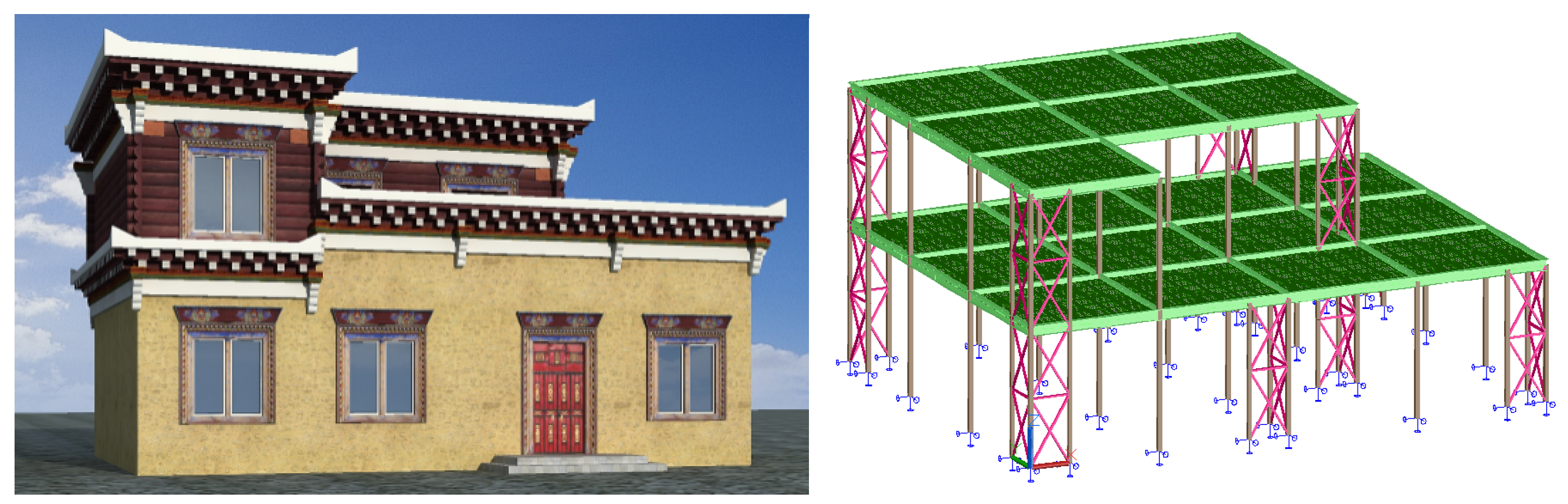
2. Engineering Background and Building Archetype

In traditional geography, the Kangba Tibetan area is one of the three major Tibetan regions in China. There are numerous low-rise ‘Folk’ residential buildings built with wood in this area. In recent years, with the expansion of the population and the need for urban construction, these traditional ‘Folk’ buildings have fueled a growing demand for wood resources which has gradually aroused awareness of ecological protection [17]. Based on a survey and mapping of typical local dwellings, this research proposes an alternative low-rise prefabricated steel structure system scheme, which is of immense significance to the protection of the local ecological environment.
Based on the field survey, various low-rise residential units were designed in this research. Taking the representative two-story residential scheme as an example, the building area of the scheme was 195 m2; the spacing between beams and columns was approximately 3.3 m, and the structural floor height was 3.3 m. Figure 1 presents the architectural drawing of the proposed project and the structural layout of the structure system. The intended design of this system is as follows: the beam-column connections and the column base joints are all bolted hinge connections; all vertical loads of the system are born by the beam and column members, while the horizontal load, such as wind and seismic actions are resisted by the bracing members. The entire structural system is an efficient force transmission system in which the vertical components bear axial forces, and the horizontal components bear bending moments.
Figure 2 presents the key components and joint constitution of the proposed braced frame system with a hinged connection in this paper. All joints, including beam-to-column connections and the column feet nodes, were hinged connections with ordinary bolts. After splitting, the length of the beam-column unit was approximately 3 m. Due to the clear force transmission path of the structural system and the high utilization rate of component materials, the steel consumption of the structural system was about 32 kg/m2. The weight of the beam-column unit was no greater than 50 kg, and the weight of the bracing unit was approximately 120 kg, which means on-site construction and installation do not rely on large-scale mechanical equipment.

3. Overview of Pseudo-Static Tests

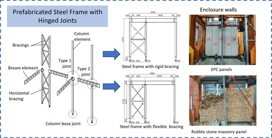
3.1. Specimen Design and Fabrication

The lateral resistance of the traditional non-braced frame structure primarily depends on the beam and column components and their connections, while the seismic performance of the braced frame system with hinged connections in this paper principally depends on the bracing system and the building envelopes. To conduct experimental verification and quantitative analysis on the lateral stiffness, deformation, energy dissipation capacity and joint reliability of the structural system, an independent sub-structure unit in the main structure was selected for experimental study, the specific geometric dimensions of which are depicted in Figure 3. All steel members were made of Q235B grade material (nominal yield strength of 235 MPa) and connected by grade 4.8 M16 (nominal diameter of 16 mm) ordinary bolts. The column members used square steel tubes with a section of 100 mm × 100 mm × 6 mm (height × width × thickness), and the beam members were H-shaped steel with a section of 250 mm × 125 mm × 6 mm × 9 mm (height × width × web thickness × flange thickness). The bracing members adopted two different sections: square steel tubes with a section of 100 mm × 100 mm × 6 mm (height × width × thickness) and round steel bars with a diameter of 12 mm, namely rigid bracings and flexible bracings. The rigid bracings were connected to the steel columns by welding, and the flexible bracings were connected through gusset plates and M16 bolts. A total of six specimens were designed, including steel frames with and without building envelopes. The enclosure walls involved the extruded cement panel (EPC) hanging board with a panel size of 2700 mm × 600 mm × 60 mm (height × width × thickness) and the rubble stone masonry panel. The ECP panels were attached to the steel frame by corner brackets and screws. The rubble stone masonry panels were connected to the steel frame by corner brackets and tie bars, which were arranged at 1/4 H, 1/2 H, and 3/4 H along the height of the steel column. Details of each specimen are presented in Table 1.

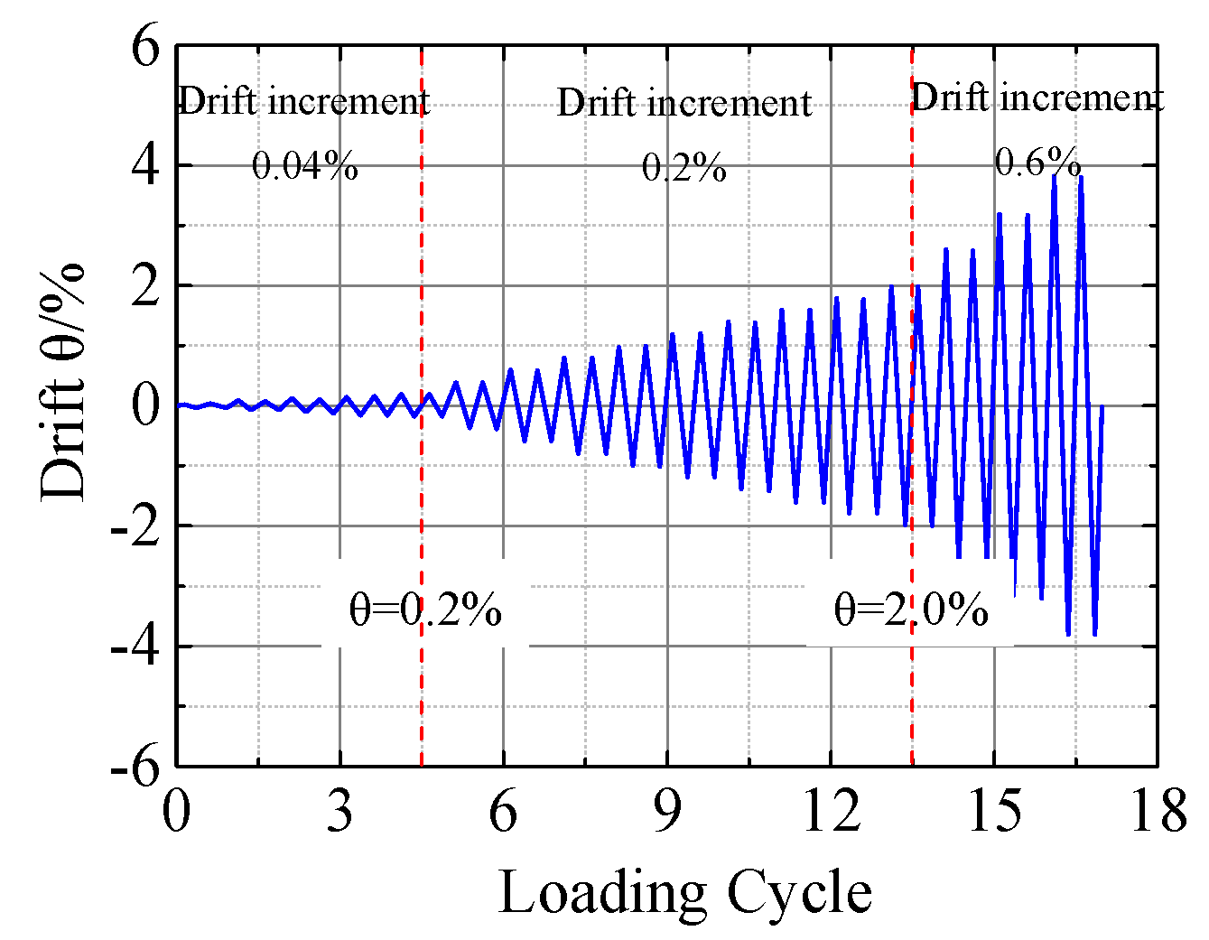
3.2. Test Setup and Loading Protocol

The test rig was composed of the reaction frame, reaction wall, lateral support, ground beam, and reaction floor, as illustrated in Figure 4. The column base joints were secured to the rigid reaction floor by anchor bolts. The vertical load was applied through a load distribution beam connected to the vertical jack. The horizontal load was applied by steel pull-rods connected to the horizontal actuator by pin connections. Two triangular reaction frames were arranged outside the plane of the frame to constrain the out-of-plane movement, one on each side, respectively. Two displacement sensors were arranged on the left side to monitor the horizontal displacement at the middle and top of the test specimen, respectively. At the beginning of the test, a vertical load of 20 kN was applied through the steel distribution beam placed on the top surface of the structural beam to simulate the uniformly distributed floor load.
The horizontal loading protocols were based on JGJ101-2015 [18] and ATC-24 [19], as shown in Figure 5. The loading rate varied based on the inter-story drift: a displacement increment of 0.04% was implemented when the story drift θ ≤ 0.2%; the displacement increment was 0.2% when the story drift 0.2% < θ ≤ 2.0%, and when the story drift θ > 2.0%, the displacement increment was set to 0.6% until the specimen was damaged.

3.3. Material Properties

Material properties of the steel members were obtained according to Chinese standards GB/T 228-2010 [20] and GB/T 2975-2018 [21]. Five groups of test coupons were prepared to examine the actual material properties of the beams, columns, rigid bracings, and beam-to-column joints in the specimen. Tensile tests of the flexible bracings were also conducted. Three tests were conducted for each component member, and the average results are provided in Table 2.
The material properties of the EPC panels were not tested in this research, and the performance index from the manufacturer is given in Table 3.

4. Test Phenomena

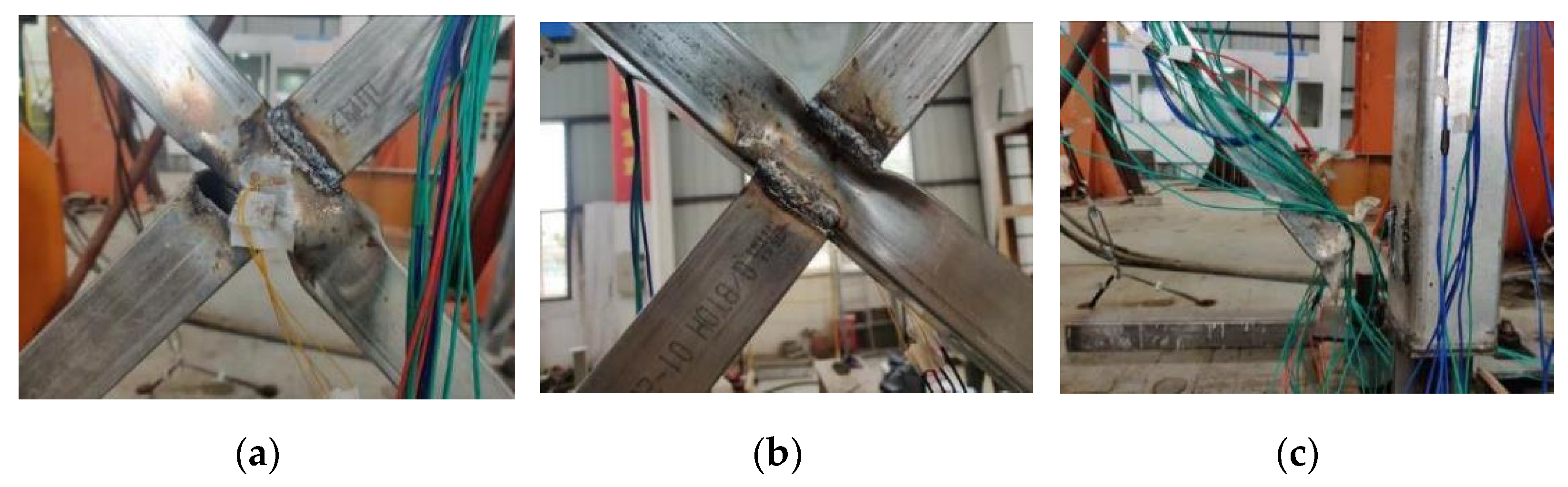
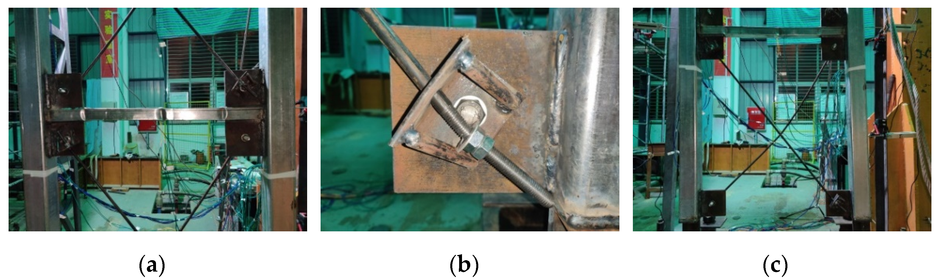
4.1. Specimens with Rigid Bracings

FW-1 specimen was a steel frame with rigid bracings, and no enclosure wallboard was attached. The observed test phenomena were as follows: when the story drift reached 0.4%, the specimen emitted a significant steel friction sound; when the story drift was 0.8%, the lower diagonal bracing had a depression of about 8 mm at the intersection; the lower diagonal bracing and the column base joint broke when the story drift reached 1.0%; the lower diagonal brace buckled near the right joint when the story drift reached 1.8%; the connection between the right lower diagonal brace and the middle of the steel column broke, and the upper diagonal brace was depressed when the story drift was approaching 2.0%; the weld between the upper bracing and the steel column broke, indicating the specimen basically lost the lateral stiffness when the inter-story drift reached 2.6%. The typical failure mode of specimen FW-1 is presented in Figure 6.
FW-2 specimen was a rigidly braced steel frame with five 60 mm-thick ECP external hanging wallboards that were numbered #1 to #5 from left to right. They were connected to the main steel structure in the form of a point hanging. The wallboards were not connected to each other. The observed test phenomena were as follows: when the inter-story drift was loaded to around 0.4%, a sound of friction between the steel members was extremely obvious; when the inter-story drift was around 0.6%, vertical cracks appeared at the right lower part of #1 slab, and the left upper part of #5 slab and the right upper corner of #4 slab were damaged; when the inter-story drift reached 0.8%, cracks appeared at the connection between the left lower part of #1 plate and the bolts; when the inter-story drift reached 1.0%, vertical cracks appeared at the upper right corner of #2 plate, and other cracks appeared at the point where the right lower part of #4 plate was connected with the bolts; when the inter-layer drift angle was 1.2%, the connection between the left upper part of the upper diagonal brace and the middle column failed, as did the intersection point of the upper diagonal brace; when the story drift was 1.4%, horizontal cracks appeared in the right lower part of #1 slab, and the joint between the left upper part of the upper inclined brace and the middle column broke; when the inter-story drift was 1.6%, the cracks in the lower part of #1 plate continued to develop; when the inter-story drift was 1.8%, the rectangular steel tube welded at the intersection of the upper inclined brace broke, the intersection node of the lower inclined brace was convex, and the upper contact part of the #4 and #5 plates was crushed; when the inter-story drift was 2.0%, the steel tube welded at the intersection point of the lower inclined brace broke, and the crack in the #1 plate continued to grow. At this time, the load fell below 85% of the ultimate load. The typical failure mode of specimen FW-2 is displayed in Figure 7.
FW-3 specimen was a rigidly braced steel frame with a 380 mm thick rubble stone masonry enclosure wall bonded with yellow mud. The corner gussets and two Ф6 tie bars were set along the height of 1/4 H, 1/2 H, and 3/4 H of the steel column. The enclosure wall was built on the outer surface of the steel structure. The pseudo-static test phenomena were as follows: when the story drift was 0.4%, the upper diagonal bracing exhibited obvious buckling at the intersection point; when the story drift was 0.6%, the lower diagonal bracing exhibited buckling at the intersection point; when the story drift was 1.0%, the cement mortar screed-coat on the top of the rubble stone wall cracked; when the story drift was 1.2%, buckling of the upper and lower diagonal bracing was obvious, and fracture occurred at the intersection point of the lower bracings and the weld joint with the steel column, while the left part of the stone masonry wall displayed a tendency to move outward; when the story drift was 1.4%, diagonal cracks appeared in the middle of the left part of the masonry wall, and the weld joint between the lower diagonal bracing and the steel column was completely torn; when loading to 1.6% story drift, the rubble stone in the middle of the left wall gradually bulged outward, a vertical crack of about 1-m length appeared in the wall, and the upper bracings were torn at the intersection and the connections with the steel columns; when the inter-story drift was 2.0%, the left wall collapsed locally and the loading stopped. The typical failure mode of specimen FW-3 is displayed in Figure 8.

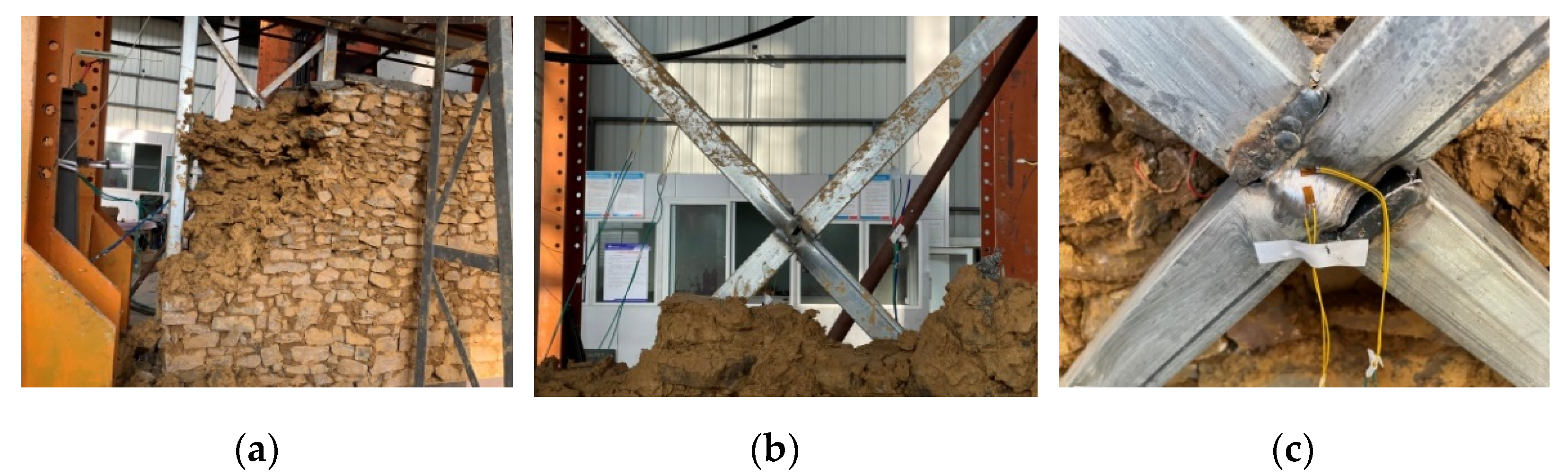
4.2. Specimens with Flexible Bracings

FW-4 specimen was a steel frame with flexible bracings, and no enclosure wallboard was attached. The lateral stiffness of the structural system decreased, and the deformation increased after the rigid braces were replaced by the flexible round steel rods. Compared with the rigidly braced specimen, no obvious failure was observed at the same story drift at the initial stage. When the inter-story drift reached 2.0%, the middle lateral brace clearly buckled; when the inter-story drift reached 2.6%, the flexible round steel rod at the gusset plate clearly bent; when the inter-story drift reached 5.0%, the horizontal actuator reached the maximum value in the reverse direction; when the positive load was 5.6% of the story drift, the horizontal load decreased to 85% of the peak load. The typical failure mode of specimen FW-4 is displayed in Figure 9.
FW-5 was a specimen with flexible bracings and five 60 mm-thick ECP external hanging wallboards. The wallboards were numbered #1 to #5 from left to right. They were connected to the main steel structure in the form of a point hanging, and the wallboards were not connected to each other. The test phenomena were as follows: when the inter-story drift was loaded to 0.8%, the left upper part of #4 slab cracked; when the inter-story drift was loaded to 1.0%, the cracks of #4 slab further expanded; when the inter-layer drift angle reached 1.2%, the right upper part of #4 slabs cracked; when the load reached 2.0%, the horizontal steel tube brace at the 1/2 H of the steel column buckled, and when the inter-story drift reached 2.6%, the weld of gusset plate between the upper diagonal brace and the middle column cracked; when the inter-story drift reached 3.2%, the right upper part of #3 plate cracked and the connection between the lateral brace and the gusset plate buckled, and the damage to #3 plate and #4 plate gradually developed as the loading preceded; when the inter-story drift reached 4.4%, the bottom connection position of #5 plate was damaged, and the top contact position of #3 plate and #4 plate crushed by extrusion; when the inter-story drift reached 5.0%, the top of #4 plate became seriously damaged and fell off, and the end of lateral bracing was seriously buckled and torn; therefore, the loading terminated. The typical failure mode of specimen FW-4 is depicted in Figure 10.
FW-6 was a specimen with flexible bracings and a 380 mm thick rubble stone masonry enclosure wall bonded with yellow mud. The corner gussets and two Ф6 tie bars were set along the height of 1/4 H, 1/2 H, and 3/4 H of the steel column. The enclosure wall was built on the outer surface of the steel structure. When the story drift was 1.8%, the lower diagonal brace and the gusset plate of the middle column cracked, and the stone masonry wall cracked locally; when the story drift was 2.0%, the lateral brace at the gusset plate of the middle column buckled slightly and cracked; when the load was further increased to 2.6%, the upper flexible diagonal brace buckled significantly; when the load was increased to 3.2%, the two ends of the lateral brace buckled severely, and the brace cracks at the gusset plate expanded further; when the story drift was 3.8%, the left part of the stone masonry wall displayed a tendency to move out-of-plane; when the story drift reached 4.4%, stones fell off the masonry wall, and large cracks appeared on the upper left side with additional stones falling off; when the story drift reached 5.0%, a large area of collapse occurred on the upper left side of the masonry wall, and the horizontal load value decreased to below 85% of the peak load. The typical failure mode of specimen FW-6 is depicted in Figure 11.

5. Analysis of Test Results and Discussions

5.1. Hysteresis Curves and the Deformation Curves of the Structure

The hysteretic curves of the six groups of specimens are presented in Figure 12. Via hysteretic curves and skeleton curves, the deformation capacity, energy dissipation performance, stiffness degradation characteristics, and other seismic performances of the structural components can be fully understood.
At the early stage of loading, no buckling occurred in the six groups of specimens. The ECP wallboards and rubble stone masonry walls were almost intact. The stiffness of the specimens did not change significantly, and the load displacement maintained a linear relationship, indicating the specimens were in the elastic working stage.
When the inter-story drift exceeded 1/250, the hysteretic curves of all specimens were pinched, and the hysteretic curves of rigidly braced specimens (FW-1 to FW-3) were plumper than those of flexible braced specimens (FW-4 to FW-6). Accordingly, specimens with rigid bracings have greater lateral stiffness; this is because specimens with rigid bracings rely on the yielding of the tube bracings to dissipate the input energy.
With the installation of the ECP external wall panels and the rubble stone masonry wallboards, the hysteretic curve of the specimen was plumper than that of the pure frame structure, and the lateral stiffness of the structure was also improved to a certain extent. Even if a weak connection between the enclosure walls and the main structure is adopted, the contact, such as the extrusion between the ECP panels and the friction between the rubble stone wall and the main frame, will have a significant impact on the seismic performance of the main structure.
The hysteretic curves of rigidly braced specimens FW-1 and FW-3 exhibited an obvious sawtooth shake in the later stage of loading due to strong nonlinear phenomena such as component buckling and weld fracture. The hysteretic curves of specimens with flexible braces, i.e., FW-4 and FW-6, were relatively smooth. The non-linear behavior mainly comprised the buckling of lateral tube braces and flexible steel rods under compression, which was relatively less severe.
When the horizontal load was unloaded to zero, the residual deformation of the specimens with flexible braces was smaller than that of the rigidly braced specimens. The reason for this is that the flexible round steel bar braces have a certain recovery capacity in the tension stage after buckling under compression.
The hysteresis curves of specimens in this research were generally less plump than the prefabricated steel-braced frame structures in Cao et al. [15]. The reason could be attributed to the low energy dissipation capacities of the two types of bracing members used in this research. The rigid bracing was prone to local buckling under reversed cyclic loading. More importantly, the welds at the X-shaped intersection were prone to tearing. While a flexible round steel bar easily buckled under compression, the energy dissipated was mainly provided by the tension member. Due to the reversed loading condition, the energy dissipation capacitary would be reduced once buckling of the bracing member occurred. Moreover, hinge connections between the beam and the column were adopted. Therefore, the plastic energy dissipation mechanism was ineffective in the joint areas.
Comparing the skeleton curves of the six groups of test specimens presented in Figure 13 reveals that:
(1) The skeleton curves of the specimens can be divided into three stages. In the linear growth stage, the displacement is small, and there is no obvious buckling and fracture in the specimens, which are basically in the elastic working state. In the deformation hardening stage, due to the characteristics of steel deformation hardening, the damage to the main beams and columns is not obvious, consisting mainly of the yielding of braces, and the lateral stiffness of specimens decreases slowly. When the peak load is reached, the braces buckle significantly, or the connection welds break, and the horizontal load increases no further. In the bearing capacity degradation stage, the skeleton curve of the bracing system decreases rapidly due to severe buckling and fracture of a large number of connection welds.
(2) At the initial stage of loading, the skeleton curves of specimens FW-1 to FW-3 and FW-4 to FW-6 are relatively coincident, which indicates that when the load is small, the deformation of the main structure and the enclosure system is relatively independent. The enclosure system makes little contribution to the stiffness of the main structure at the elastic stage.
(3) At the middle and later stages of loading, the lateral stiffness of FW-2 and FW-3 is significantly improved compared with FW-1, while the lateral stiffness of FW-5 and FW-6 is notably enhanced in comparison with FW-4. This indicates that the enclosure system contributes significantly to the lateral rigidity of the frame structure when the deformation of the substructure is large at the middle and later stages of loading. Furthermore, the skeleton curves of the rigidly braced specimens (FW-1,FW-2 & FW-3) all have a descending stage.
The yield load, ultimate load, and corresponding deformation value of each test piece were determined according to the equivalent energy method [18], as shown in Figure 14. The load characteristics of each specimen were obtained, and detailed results are presented in Table 4. Overall, the yield displacement in the positive direction of six specimens was greater than in the negative direction. The yield displacements of specimens FW-2 and FW-3 were close to each other, and all less than the yield displacement of specimen FW-1. The yield displacement of specimens FW-4 to FW-6 was larger than that of the rigidly braced specimens, but the yield load and ultimate load were relatively small.

5.2. Stiffness Degradation Characteristics

The stiffness degradation of each specimen is described by the loop secant stiffness in Chinese standard JGJ/T 101 [18]. The stiffness degradation in the positive direction (PD) and negative direction (ND) was analyzed, respectively. The loop secant stiffness is expressed as follows:
K j = i = 1 n P j i / i = 1 n u j i
where P j i —the maximum load value of the ith cycle when the jth level is loaded.
u j i —the deformation value corresponds to the maximum load of the ith cycle when the jth level is loaded.
n—The number of cycles of the jth load level.
The stiffness degradation curves of all specimens are shown in Figure 15. As we can see, the initial stiffness of specimen FW-1 ranged from 3.08 kN/mm to 3.56 kN/mm, while the initial stiffness of specimen FW-2 ranged from 3.56 kN/mm to 3.61 KN/mm, and the initial stiffness of specimen FW-3 ranged from 5.18 kN/mm to 5.54 KN/mm. The initial stiffness of specimen FW-4 ranged from 0.75 kN/mm to 0.937 kN/mm, the initial stiffness of specimen FW-5 ranged from 1.54 kN/mm to 2.29 kN/mm, and the initial stiffness of FW-6 ranged from 2.44 kN/mm to 3.33 kN/mm. The contribution of the initial stiffness of the external stone masonry was greater than that of the external ECP panel. The stiffness degradation of the rigidly braced specimens was relatively fast. In contrast, the stiffness degradation of the flexibly braced specimens tended to be gentle in the later period. The stiffness degradation curves of the six groups of specimens exhibited good continuity.

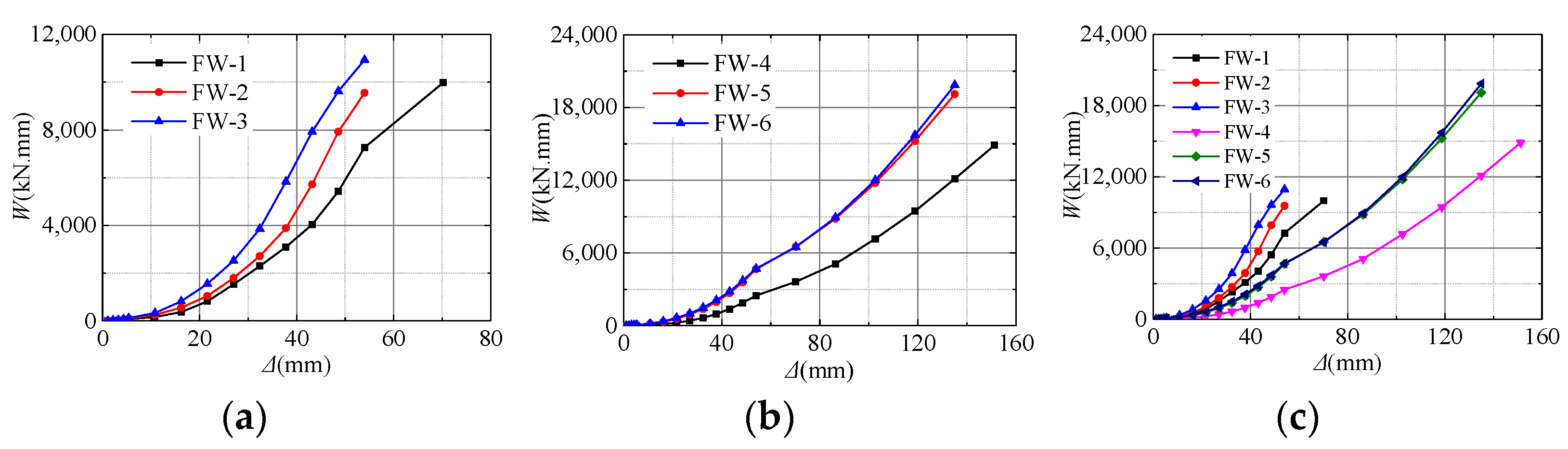
5.3. Energy Dissipation Capacity

To quantitatively evaluate the energy dissipation capacity of structures, the cumulative energy dissipation and equivalent viscous damping coefficient ζeq are typically considered. Referring to the recommendations in JGJ/T 101-2015 [18], the cumulative energy dissipation of the six specimens is represented by the cumulative area enclosed by the hysteresis curve during each stage of cyclic loading, as shown in Figure 16. The first cycle of all levels of loading was utilized to calculate the equivalent viscous damping coefficient, as shown in Figure 17.
Compared with the flexibly braced specimens, the rigidly braced specimens dissipated more energy during the early stage of loading, but the ductility of the structure was gradually lost in the later stage due to serious damage to the bracing system. The deformation capacity of the flexibly braced specimen was large; the structural members yielded gradually began to participate in energy dissipation in the later stage of loading. The equivalent viscous damping coefficient ζeq of the pure steel frame was approximately 4%. The equivalent viscous damping coefficient ζeq was greatly increased due to the contribution of the enclosure wall in the energy dissipation for both rigidly and flexibly braced specimens. The enclosure system contributed more to the stiffness and energy dissipation of the flexibly braced specimens, with an equivalent viscous damping coefficient ζeq between 6–7%.

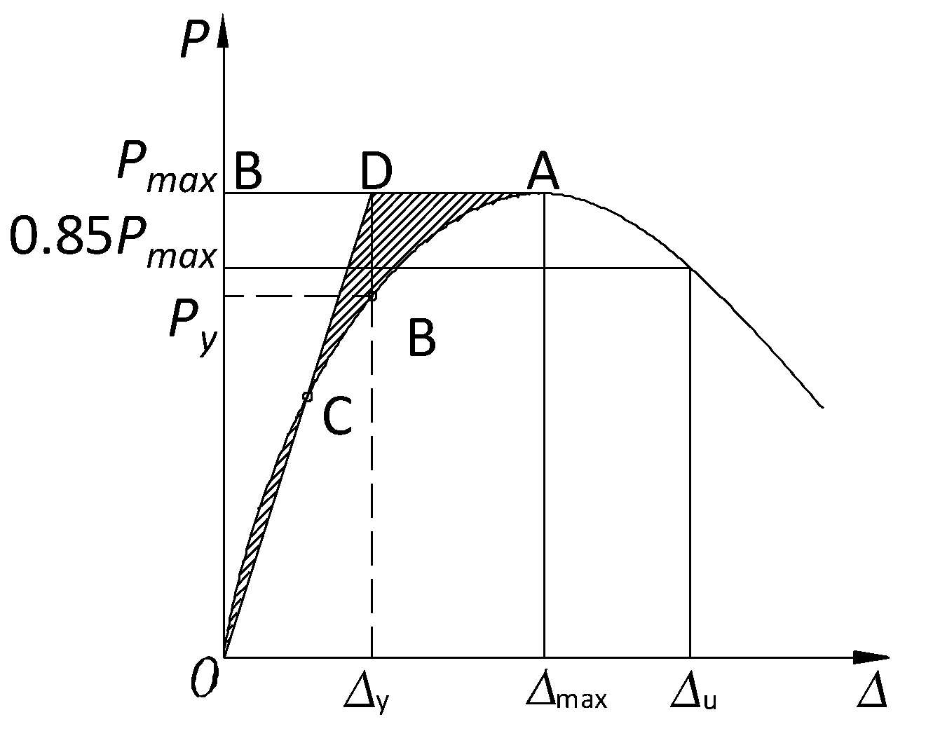
5.4. Ductility Factor

The ductility coefficient is usually employed to evaluate the deformation capacity before the bearing capacity decreases. Ductility factors can be divided into the curvature ductility factor, displacement ductility factor, and rotation ductility factor [22]. The displacement ductility coefficient and rotation ductility coefficient were employed to analyze the ductility characteristics of the specimens in this paper. The displacement ductility factor μ is defined as the ratio of the ultimate displacement Δu to the yield displacement Δy of the specimen at the top of the column, while the rotation ductility factor μθ is defined as the ratio of the ultimate drift θu to the yield drift θy.
μ = Δ u Δ y
μ θ = θ u θ y
where θ u = arctan ( Δ u / h ) , θ y = arctan ( Δ y / h ) .
Table 5 presents the displacement ductility coefficient μ and the rotation ductility coefficient μθ based on the skeleton curves of the six sets of specimens. The test results indicate that the braced system was most seriously damaged in the substructure and that the damage to the beam and column components was relatively slight. After the braces failed, the horizontal bearing capacity of the structure system decreased rapidly. The ductility coefficient of all specimens ranged between 1.4 and 1.9, which indicates that the energy dissipation mechanism of the substructure system was relatively simple and that the structure system mainly relies on the lateral stiffness and elastic deformation capacity to resist seismic action rather than the ductility of the structure after entering the plastic state.

6. Conclusions

Based on a survey and mapping of typical local dwellings in the Kangba Tibetan area, an alternative low-rise prefabricated steel frame system with hinged joints was proposed in this research. The key substructure in the system was selected for quasi-static tests with different building envelopes. The failure modes, as well as key parameters such as bearing capacity, energy dissipation, and stiffness characteristics of the specimens, were analyzed. The major findings of the research are as follows:
(1) All the specimens revealed a failure of the bracing system, and the main beam and column components were basically intact, which’s convenient for post-earthquake reinforcement and maintenance of the building structures. The rigidly braced specimen was mainly damaged by buckling, yielding, and tearing, and the flexibly braced specimen was mostly damaged by buckling, yielding, and node failure.
(2) The joints of the structural system were hinged, and the energy dissipation of the specimens primarily depended on lateral force-resistant components such as braces and enclosure walls; therefore, the hysteretic curve was relatively empty. The flexible bracing system, in particular, stored principally elastic strain energy in the early stage of loading.
(3) The six groups of specimens were in an elastic working state within 1/250 inter-story drift. The bearing capacity of FW-1 to FW-3 rigid-bracing specimens did not decrease significantly when the inter-story drift reached 1/60. Furthermore, FW-4 to FW-6 flexible-bracing specimens continued to exhibit large bearing capacity when loaded to 1/30 inter-story drift. During the later stage of loading, the horizontal bearing capacity of the flexibly braced specimen was basically the same as that of the rigidly braced specimen.
(4) The enclosure system contributed significantly to the lateral stiffness of the specimen. The initial stiffness of the FW-2 specimen with ECP panels ranged from 3.56 kN/mm to 3.61 kN/mm, while that of the FW-3 specimen with stone masonry walls ranged from 5.18 kN/mm to 5.54 kN/mm. The initial stiffness was 1.2 times and 1.7 times that of FW-1, respectively. The initial stiffness of the specimen FW-5 with ECP plates ranged from 1.54 kN/mm to 2.29 kN/mm, while the initial stiffness of the specimen FW-6 with stone masonry walls ranged from 2.44 kN/mm to 3.33 kN/mm. The initial stiffness was 2.0 times and 3.3 times that of FW-4 with flexible bracings, respectively.
(5) The equivalent viscous damping coefficient ζeq of the pure frame without an enclosure system was approximately 4%. In the later period of loading, the enclosure system gradually participated in energy dissipation, and the equivalent viscous damping coefficient ζeq of the entire structure reached 6–8%.
(6) The simplified beam-column joint is the core feature of the proposed structure system. Under low cyclic loading, the ductility coefficient of the frame bracing system was between 1.4 and 1.9, i.e., in non-ductile failure mode.
(7) The rigidly braced specimen was prone to welding failure and sheet tearing at the connection positions. The shear strength and the stiffness of the substructure decrease rapidly after the peak load. Replacement of the rigid bracing member was also labor-intensive and time-consuming. It is therefore recommended to use the flexible bracings as lateral force-resisting members in the structural system.

Author Contributions

Conceptualization, Y.W. and T.W.; methodology, B.J.; investigation, B.J.; resources, W.Z.; data curation, B.J.; writing—original draft preparation, B.J.; writing—review and editing, W.Z. and S.Y.; visualization, B.J. and W.Z.; supervision, Y.W. and T.W.; project administration, B.J.; funding acquisition, B.J., W.Z. and S.Y. All authors have read and agreed to the published version of the manuscript.

Funding

This research was supported by Sichuan Science and Technology Program, grant number 2019YFS0071, National Natural Science Foundation of China, grant number 52008008, and Shanghai Rising-Star Program, grant number 21QB1406400.

Institutional Review Board Statement

Not applicable.

Informed Consent Statement

Not applicable.

Data Availability Statement

Data will be made available on request.

Acknowledgments

This research was sponsored by the Sichuan Science and Technology Program, No.2019YFS0071, and the National Natural Science Foundation of China, No. 52008008. The research was also partially sponsored by Shanghai Rising-Star Program No.21QB1406400. Any opinions, findings, conclusions, or recommendations expressed in this article are those of the authors and do not necessarily reflect the views of the sponsors.

Conflicts of Interest

The authors declare no conflict of interest.

References

  1. Xu, Y.; Guan, H.; Zhou, X.; Loo, Y. Preliminary seismic analysis of fabricated steel frame systems with pin beam-column connections and buckling restrained braces. In Proceedings of the International Conference on Performance-Based and Life-Cycle Structural Engineering, Brisbane, QLD, Australia, 9–11 December 2015. [Google Scholar]
  2. Li, G.; Li, J. Advanced Analysis and Design of Steel Frames; John Wiley & Sons: Hoboken, NJ, USA, 2007. [Google Scholar]
  3. Astaneh, A. Demand and supply of ductility in steel shear connections. J. Constr. Steel Res. 1989, 14, 1–19. [Google Scholar] [CrossRef]
  4. Elnashai, A.S.; Elghazouli, A.Y. Seismic behaviour of semi-rigid steel frames. J. Constr. Steel Res. 1994, 29, 149–174. [Google Scholar] [CrossRef]
  5. Nader, M.N.; Astanehasl, A. Shaking table tests of rigid, semirigid, and flexible steel frames. J. Struct. Eng. 1996, 122, 589–596. [Google Scholar] [CrossRef]
  6. Türker, T.; Kartal, M.E.; Bayraktar, A.; Muvafik, M. Assessment of semi-rigid connections in steel structures by modal testing. J. Constr. Steel Res. 2009, 65, 1538–1547. [Google Scholar] [CrossRef]
  7. Guo, B.; Su, M.; Lei, S. Experimental behavior of rigid and semirigid steel frames under cyclic loading. In Proceedings of the 12th International Conference on Engineering, Science, Construction, and Operations in Challenging Environments—Earth and Space 2010, Honolulu, HI, USA, 14–17 March 2010. [Google Scholar]
  8. Rigi, A.; Javidsharifi, B.; Hadianfard, M.A.; Yang, T.Y. Study of the seismic behavior of rigid and semi-rigid steel moment-resisting frames. J. Constr. Steel Res. 2021, 186, 106910. [Google Scholar] [CrossRef]
  9. Abidelah, A.; Bouchaïr, A.; Kerdal, D.E. Experimental and analytical behavior of bolted end-plate connections with or without stiffeners. J. Constr. Steel Res. 2012, 76, 13–27. [Google Scholar] [CrossRef]
  10. Wong, C.W.; Mak, W.H.; Ko, J.M. System and parametric identification of flexible connections in steel framed structures. Eng. Struct. 1995, 17, 581–595. [Google Scholar] [CrossRef]
  11. Khoo, H.; Clifton, C.; Butterworth, J.; Macrae, G. Experimental study of full-scale self-centering sliding hinge joint connections with friction ring springs. J. Earthq. Eng. JEE 2013, 17, 972–997. [Google Scholar] [CrossRef]
  12. Wei, J.; Tian, L.; Guo, Y.; Qiao, H.; Bao, Y.; Jiao, Z.; Shi, X. Numerical study of the seismic performance of a double-hinge steel frame joint. J. Constr. Steel. Res. 2021, 187, 106963. [Google Scholar] [CrossRef]
  13. Zheng, L.Q.; Yan, G.Y.; Wei, C.G.; Ma, Y.C. Experimental and numerical investigation of steel energy-dissipating hinge under cyclic loading. China Civil Eng. J. 2020, 53, 29–43. (In Chinese) [Google Scholar]
  14. Cao, X.; Feng, D.; Wu, G.; Wang, Z. Experimental and theoretical investigations of the existing reinforced concrete frames retrofitted with the novel external SC-PBSPC BRBF sub-structures. Eng. Struct. 2022, 256, 113982. [Google Scholar] [CrossRef]
  15. Cao, X.; Feng, D.; Wang, Z.; Wu, G. Parametric investigation of the assembled bolt-connected buckling-restrained brace and performance evaluation of its application into structural retrofit. J. Build. Eng. 2022, 48, 103988. [Google Scholar] [CrossRef]
  16. Chen, Y.; Chen, C. Study on seismic performance of prefabricated self-centering steel frame. J. Constr. Steel. Res. 2021, 182, 106684. [Google Scholar]
  17. Huang, S.; Liu, B.; Zhou, Y. Economic and social benefit analysis on structural renewal and renovation project of daofu folk house. Value Eng. 2019, 25, 74–75. (In Chinese) [Google Scholar]
  18. JGJ/T 101; Technical Specification for Steel Structures of Tall Buildings. China Building Industry Press: Beijing, China, 2015.
  19. ATC-24; Guidelines for Cyclic Seismic Testing of Components of Steel Structures. Applied Technology Council: Redwood City, CA, USA, 1992.
  20. GB/T 228-2010; Metallic Materials-Tensile Testing–Part 1: Method of Test at Room Temperature. Standards Press of China: Beijing, China, 2010.
  21. GB/T2975-2018; Steel and Steel Products-Location and Preparation of Samples and Test Pieces for Mechanical Testing. Standards Press of China: Beijing, China, 2018.
  22. Qiu, C.X. Investigations of the Hysteresis Performance of the Steel Frames Infilled with Composite Panels. Master’s Thesis, Shandong University, Jinan, China, 2011. (In Chinese). [Google Scholar]
Figure 1. Architectural drawing and structural layout.
Buildings 12 02088 g001
Figure 2. Schematic drawing of the structural system.
Buildings 12 02088 g002
Figure 3. Schematic drawings of test specimens: (a) Rigid bracing; (b) Flexible bracing. (Unit: mm).
Buildings 12 02088 g003
Figure 4. Test setup: (a) Schematic drawings; (b) On-site photo.
Buildings 12 02088 g004
Figure 5. Loading protocol.
Buildings 12 02088 g005
Figure 6. Test phenomena of FW-1 specimen: (a) Welding failure at the intersection of the lower bracings; (b) Buckling of the upper brace; (c) Welding failure at the end of the lower brace.
Buildings 12 02088 g006
Figure 7. Test phenomena of FW-2 specimen: (a) Wall panel numbering sequence; (b) Wallboard crushed and broken; (c) Tearing failure at the end of the upper brace.
Buildings 12 02088 g007
Figure 8. Test phenomena of FW-3 specimen: (a) Partial collapse of the left part wall; (b) Fracture failure at the intersection of upper bracings; (c) Welding failure at the intersection of the lower brace.
Buildings 12 02088 g008
Figure 9. Test phenomena of FW-4 specimen: (a) Horizontal brace buckling; (b) Bending of the flexible bracings; (c) Brace deformation at the end of the test.
Buildings 12 02088 g009
Figure 10. Test phenomena of FW-5 specimen: (a) Tear failure of the horizontal brace; (b) Wallboard crushed and broken; (c) Bracing deformation by the end of the test.
Buildings 12 02088 g010
Figure 11. Test phenomena of FW-6 specimen: (a) Partial collapse of the left part wall; (b) Buckling and tear failure of the horizontal brace; (c) Deformation of upper bracings.
Buildings 12 02088 g011
Figure 12. Hysteretic curves: (a) FW-1 specimen; (b) FW-2 specimen; (c) FW-3 specimen; (d) FW-4 specimen; (e) FW-5 specimen; (f) FW-6 specimen.
Buildings 12 02088 g012
Figure 13. Comparisons of skeleton curves: (a) Specimens with rigid bracings; (b) Specimens with flexible bracings; (c) Comparison of all specimens.
Buildings 12 02088 g013
Figure 14. Illustration of the equivalent energy method [18].
Buildings 12 02088 g014
Figure 15. Stiffness degradation: (a) Specimens with rigid bracings; (b) Specimens with flexible bracings; (c) Comparison of all specimens.
Buildings 12 02088 g015
Figure 16. Comparisons of cumulative energy consumption curves: (a) Specimens with rigid bracings; (b) Specimens with flexible bracings; (c) Comparison of all specimens.
Buildings 12 02088 g016
Figure 17. Comparisons of the equivalent viscous damping coefficient: (a) Specimens with rigid bracings; (b) Specimens with flexible bracings; (c) Comparison of all specimens.
Buildings 12 02088 g017
Table 1. Details of specimens.
Specimen No.ColumnsBeamsBracingsExternal
Wallboards
FW-1□100*100*6H250*125*6*9□50*50*2
FW-2□100*100*6H250*125*6*9□50*50*2ECP
FW-3□100*100*6H250*125*6*9□50*50*2masonry
FW-4□100*100*6H250*125*6*9Ф12 steel bar
FW-5□100*100*6H250*125*6*9Ф12 steel barECP
FW-6□100*100*6H250*125*6*9Ф12 steel barmasonry
Table 2. Material properties of the steel members.
Component MemberYield Stress
f y (MPa)
Tensile Stress
f μ (MPa)
Elastic Modulus (GPa)Elongation
(%)
Rigid bracing368.12435.21192.8521.93
Flexible bracing407.42505.48211.78823.30
Cloumn390.03444.44209.1424.97
Beam-flange284.81415.00207.3738.58
Beam-web249.28430.04209.3041.19
Joint276.45417.71213.9845.63
Table 3. Material properties of the EPC panels.
ItemsRequirementsTested Results
Compressive stress (Mpa)≥3.535.4
Hanging capacityCrack width ≤0.5mm when loaded to 1.2 kN.Loaded to 0.5 kN-holding 2 mins-loadted to 1.2 kN, crack width ≤0.5 mm.
Impact strengthNo penetrating cracks after 5 impact loading.No penetrating cracks after 5 impact loading.
CombustibilityIncombustibilityFurnace temperature (°C)≤303
Duration of combustion (s)00
Mass loss (%)≤5016
Calorific value
(MJꞏkg−1)
≤2.00.3
Drying shrinkage (mmꞏm−1)≤0.60.44
Sound reduction index (dB)4048
Thermal resistance (W/(m2ꞏK))≥0.651.49
Table 4. Load characteristics.
Specimen No.Directions Δ y (mm) P y (kN) Δ m a x (mm) P m a x (kN) Δ u (mm) P u (kN)
FW-1PD40.4852.7848.5559.8859.8650.90
ND−29.64−39.37−45.39−47.28−56.93−40.19
FW-2PD29.5437.0142.8744.9146.8938.17
ND−24.98−46.06−42.83−53.41−45.90−45.40
FW-3PD30.9346.7037.8049.9548.3632.13
ND−20.60−48.22−31.72−55.56−35.90−47.22
FW-4PD113.0037.47146.341.35160.7235.15
ND−83.00−30.84−118.10−35.92−30.53
FW-5PD114.6435.62150.5441.49
ND−74.80−31.32−118.92−38.74
FW-6PD75.9129.77102.1536.14122.430.72
ND−73.50−38.04−118.1−46.97−125.7839.72
Note: The hysteretic curves of specimens FW-4 and FW-5 do not contain the descending stage, so the ultimate load and displacement are not given.
Table 5. Ductility coefficients.
Specimen No.Directions Δ y (mm) Δ u (mm) θ y (mrad) θ u (mrad) μ   ( μ θ )
FW-1PD40.559.915.022.21.5
ND−29.6−56.911.021.11.9
FW-2PD29.546.911.017.41.6
ND−25.0−45.99.317.01.8
FW-3PD30.948.411.517.91.6
ND−20.6−35.97.613.31.7
FW-4PD113.0160.741.959.51.4
ND−83.030.7
FW-5PD114.642.5
ND−74.827.7
FW-6PD75.9122.428.145.31.6
ND−73.5−125.827.246.61.7
Note: The hysteretic curves of test pieces FW-4 and FW-5 have no descending stage; therefore, the limit displacement is not given.
Publisher’s Note: MDPI stays neutral with regard to jurisdictional claims in published maps and institutional affiliations.

