Article

Quantification of the Transversal Fiber Strand Stiffness of Textiles Used in Textile-Reinforced Concrete via Shore Hardness

Chair of Building Materials, Technische Universität Dortmund, August-Schmidt-Str. 8, 44227 Dortmund, Germany
*
Author to whom correspondence should be addressed.
Buildings 2022, 12(11), 2038; https://doi.org/10.3390/buildings12112038
Submission received: 21 October 2022 / Revised: 10 November 2022 / Accepted: 15 November 2022 / Published: 21 November 2022
(This article belongs to the Section Building Materials, and Repair & Renovation)

Abstract

:
Textile-reinforced concrete is characterized by its high-performance load-bearing behavior. The basis of these properties is largely determined by the characteristics of the textile used. The textile in turn consists of fibers that are bonded together by means of a matrix (impregnation). Both the fiber material and the impregnation significantly influence the tensile and bonding properties of the textile. The performance of the impregnation depends largely on its stiffness. In this publication, the fiber strand stiffness is quantified by means of shore hardness measurements, and the influence of the fiber strand stiffness on the tensile and composite properties is presented. The Shore hardness is a kind of Young’s modulus. The tests can be performed on the end product (manufactured fiber strand) with little effort. The test setup was adapted to determine the Shore hardness on the fiber strand. A comparison between the hardness and tensile strength shows a direct correlation. A dependency can also be identified and described of the bond between the textile and the concrete and the hardness. The investigations shown make quantifying the fiber strand stiffness based on hardness appear reasonable.

1. Introduction

1.1. Textile-Reinforced Concrete

Textile-reinforced concrete (TRC) is a composite material consisting of high-performance technical textiles and a fine-grained concrete. The fine-grained concrete takes on the compressive forces, while the textiles receive the tensile forces. The concrete not only differs in grain size of the aggregate but also has a higher compressive strength to match the high-performing textiles. The textiles do not need a high concrete cover to be durable because they do not corrode in nonalkaline environments the way steel reinforcement does. Thus, the concrete cover can be reduced to the minimum necessary for the bonding. This in turn leads to textile-reinforced concrete having many advantages when it comes to sustainability. TRC structures can be manufactured with smaller amounts of resources such as cement, sand and of course steel, which also leads to a smaller environmental impact. Additionally, these structures inherently have longer service lives than regular concrete structures. Finally, TRC can also be used to extend the service life of old concrete structures when it is used as for repair or strengthening [1,2]. In recent years, textile-reinforced concrete components with slender structures such as footpaths and cyclist bridges [3,4], sandwich panels [5,6,7], façade panels [8] and noise barrier walls [9,10] have been constructed as pilot projects. The use of textile-reinforced concrete to strengthen or repair existent concrete structures has also been studied and developed [11,12,13].
The maximum load of a TRC component is in case of a failure of the tensile zone directly connected to the tensile strength of the textile. The choice of fiber material therefore has a decisive influence on the subsequent load-bearing capacity of the component. A fiber strand, also called roving, consists of many thousands (k) of single fibers (e.g., 48 k = 48,000 single fibers). Basalt, carbon and glass fibers are used as fiber materials at industrial scale [14]. The materials differ concerning the mechanical properties and durability in the alkaline milieu of the concrete. Table 1 gives an overview of the mechanical properties of the three different raw fiber materials.

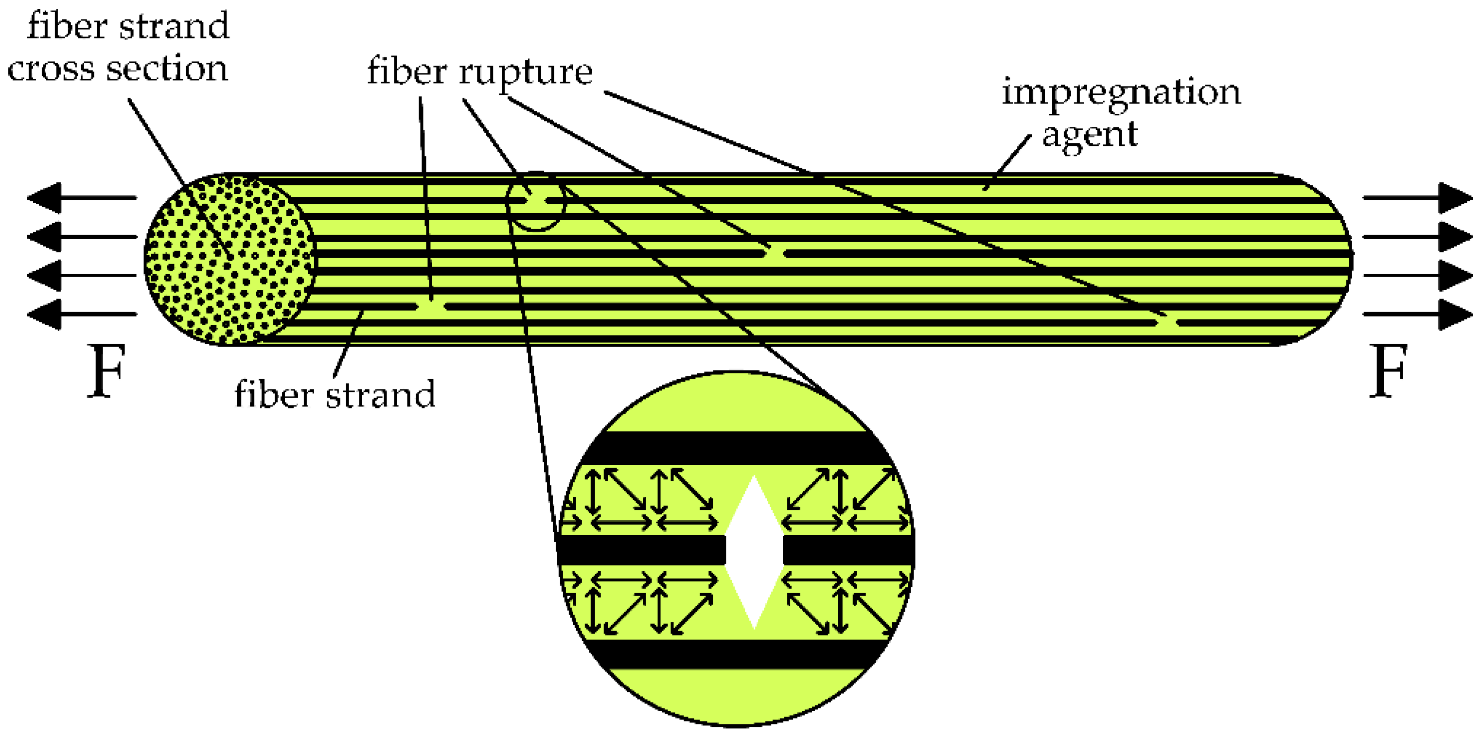
1.2. Influencing Parameters on the Tensile Strength of Impregnated Fiber Strands

In the beginning of the research on TRC, textiles without impregnation were used [16]. Later on, the vast possibilities available with impregnation became clear. However, to fully utilize the tensile strength of the fiber material, all fibers in the roving would have to be loaded absolutely evenly. This case is theoretical. In case of an unimpregnated fiber strand embedded in concrete, only the outset fibers that are in direct contact with the concrete are loaded fully. The forces are transferred to the inner fibers only via friction. This friction is low, and consequently the inner fibers are nearly unloaded. Figure 1 shows the stress distribution in the cross-section of the fiber strands embedded in concrete with different degrees of impregnation. With increasing impregnation, the stresses become more even due to the improvement of the so-called inner bond between the single fibers. In a fully impregnated fiber strand (Figure 1 right), the stresses are nearly constant over the whole cross-section.
First, the penetration capacity of the impregnation material relates to the fiber strength. Only in a fully impregnated fiber strand can all single fibers participate in the load transfer. To create an impregnated textile, first a fiber strand made of the raw material is produced and rolled on a spool. Then, the spooled fiber strands are used to produce the textile in a warp knitting machine. In general, the textiles for use in TRC are produced as nonwoven fabrics to reduce the structural elongation. Directly after the knitting, the textile is impregnated by passing a tub (foulard) with the impregnation agent and some squeeze rollers. The squeeze rollers press the impregnation agent into the fiber strand and absorb excess material [15].
If complete impregnation is not achieved (see Figure 2a) across the yarn cross-section, the number of activated fibers is reduced and thus also the tensile strength of the strand. In addition to homogenizing the stresses in the cross-section, the impregnation material also bridges fiber breaks along the length of the roving (see Figure 2b). These fiber ruptures occur during the manufacturing of the fiber strand due to the high transverse pressure sensitivity of the fibers.
If there is a fiber break in the strand, the forces of this fiber are transferred to the surrounding fibers (Figure 3). While in an unimpregnated fiber strand, the forces can only be transferred via friction, the load transfer via the impregnation agent works much more efficiently. The so-called inner bond of the fiber strand is clearly increased. The more powerful the impregnation material, the better the forces can be transferred and the greater the tensile strength of the yarn (compare [17]).
In addition to improving the mechanical properties of the fiber strand, the impregnation agent is also used to increase the durability of the raw fibers. Glass fibers (also AR-glass) lose their strength in alkaline environments such as concrete over time [19,20,21]. This loss can clearly be reduced by impregnating the fiber strand [22].
To impregnate fiber strands for use in TRC, mineral-based [23,24] or polymer-based [14] impregnation agents are used. Mineral impregnation agents have high resistance against high temperatures, and if they are used in combination with mineral fibers (glass or basalt), the whole TRC component is mineral based. Currently, mineral-impregnated textiles and fiber strands are only available for research and are produced in small batches in the laboratory. The textile industry uses polymers such as resins based on epoxy (EP), vinyl ester (VE), styrene–butadiene rubber (SBR) and acrylates (ACR). These impregnation agents differ concerning the mechanical properties (see Table 2).
SBR shows the lowest tensile strength and has a small Young’s modulus. The strength of the acrylate is about three to four times higher than that of the SBR, while EP has an even higher tensile strength. Additionally, the Young’s modulus of EP was the highest of the three materials. The mechanical properties of the impregnation agent are also visible in the tensile strengths of impregnated textiles. Figure 4 shows the tensile strengths of exemplary fiber strands impregnated with different polymeric agents.
As fiber material for all strands, a 48 k roving made of carbon fibers is chosen. The results are in order of the simplified qualitative description of the fiber strand stiffness in order of tensile strength of the impregnation materials: SBR = soft, ACR = medium stiff, epoxy = stiff (compare Table 2). The SBR-coated one has the lowest strength (2334 MPa). Acrylic impregnation (identical material for all three strands) leads to performance between 3139 and 3552 MPa, while the epoxy-coated one nearly reaches a fiber strength of about 4400 MPa. This means that the tensile strengths of the fiber strands fit the mechanical properties of the impregnation agents in a qualitive way. A direct quantitative correlation between the properties of the impregnation material, e.g., the tensile strength and the performance of the fiber strand, cannot be seen.

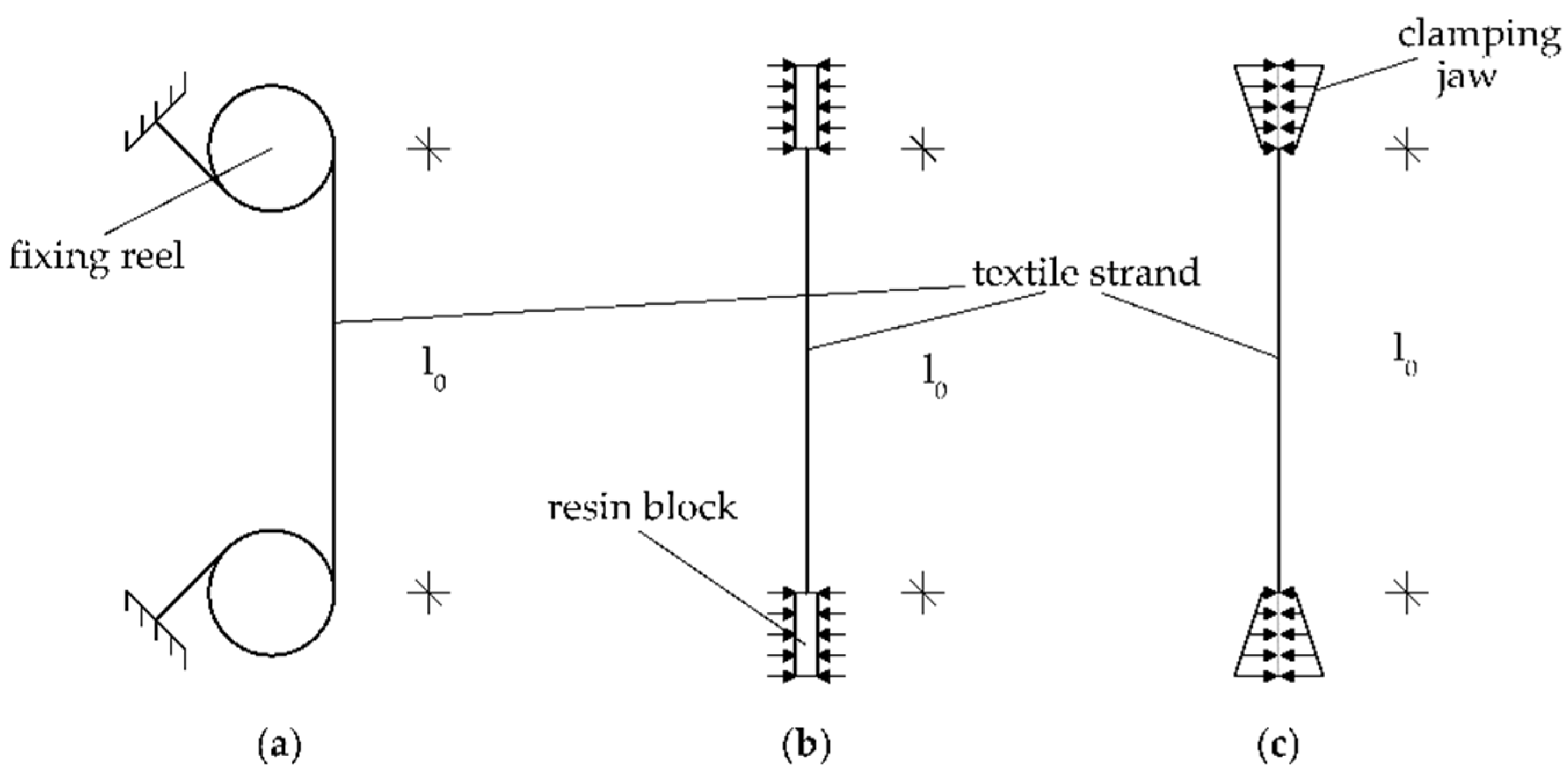
1.3. Characterization of the Tensile Strength of Fiber Strands

There are several methods available for determining the tensile strength of technical textiles. Here, only the testing of individual fiber strands is addressed. Because technical textiles are sensitive to transverse pressure, the clamping of the textiles has to be specifically adjusted depending on the stiffness of the impregnation. For textiles with a softer impregnation or without an impregnation, the testing described in ISO 3341 [26] is suitable. This measurement includes rolling the textile strand up on two reels on both sides of the strand to hold it; see Figure 5a.
This method is not an option for textiles with a stiff impregnation because the small radius of the reel will lead to breaks in the impregnation of the strand. For stiff impregnated textiles, the testing regulated under EN ISO 10618 [27] is applicable, where two different types of clamping are described. Either both ends of the textile strand are embedded in resin to create two blocks to introduce the force (Figure 5b) or the yarn is clamped directly at both ends (Figure 5c). The first method is rather disadvantageous because it is very time-consuming, although the method with direct clamping can also be problematic because the clamping jaws made of metal are much harder than the impregnation of the fiber strand. This can damage the fibers and ultimately lead to tension peaks and the failure of the yarn at the clamp. One solution is to lengthen the clamping jaw to achieve the smooth transmission of force into the fiber strand (compare [28,29,30]).
A suitable test for all kinds of textiles is the compound tensile test, whereby the textiles are embedded in concrete and tested in the concrete specimen. Test setups of this method can be found in [10,23,31,32]. The method also considers the influence of the concreting process on the strength. The test results are only valid if a breaking of the fiber strands is observed as a failure mode and no bond failure of the anchorage occurs. In general, several fiber strands are tested in one specimen. Consequently, the measured strengths are a bit lower compared with testing the single fiber strand due to statistic and the uneven loading of the fiber strands in the specimen.

1.4. Influencing Parameters on the Bond Performance of TRC

The load-bearing behavior of TRC components is mainly influenced by the bond between the textiles and the concrete. Using unimpregnated yarns, the cementitious matrix can penetrate into the outer zone of the yarn; the penetration depth depends on the yarn geometry and the viscosity of the cementitious matrix. The outer filaments of the yarn are directly activated via the concrete, while the inner filaments are only loaded via the friction between filaments. The impregnation material homogenizes the tensile tensions across the cross-section and also prevents the penetration of the cementitious matrix into the yarn. The bond forces must transfer between the surface of the impregnated yarn and the concrete. Here, three different bond types can be activated [33]. First, the adhesive bond is activated, which leads to a stiff bonding. When the adhesive bonding is exceeded, the bond forces can transfer via friction and form fit. While the friction is mainly influenced by the surface of the yarn and its geometry, the form fit depends on the widening of the yarn cross-section and the stiffness of the impregnation material [17].
At the junction point of the 0° (loaded) and the 90° strands (see Figure 6), both strands are compressed, and the fiber strand’s cross-section is reduced compared with the one in the middle between the junction points. If the 0° fiber strand is pulled out of the concrete, the wider cross-section has to pass the smaller channel in the concrete. Thus, the fiber strand has to be compressed. The resistance against this compression influences the bond performance and depends on the transversal stiffness of the fiber strand [34].
In references [35,36], the influence of the yarn as well as the concrete on the maximum bond is evaluated. For this, four textiles made of 48 k carbon rovings were tested in combination with varying concretes using a single-sided pullout test. The textiles differed in yarn geometry (T1, T1b, T2) and impregnation agent (A = acrylic, B = SBR). In the first step, the textiles were tested in combination with two concretes with compressive strengths of C1 = 100 MPa and C2 = 130 MPa (see Figure 7).
Comparing the results for Textile 1 (T1), the influence of the impregnation material becomes clear. The maximum bond flow of the acrylic impregnated textile is more than four times higher than the SBR-impregnated one, independent of the concrete. Textile T1b is a variation of textile T1 with slightly different geometrical properties. These changes increased the bond performance by 35%. To investigate the influence of the concrete properties on the bond performance, textile T2A was tested in combination with various concretes (see Figure 3b). It became clear that with increasing concrete strength, the maximum bond flow also increases. Compared with the influence of the yarn geometry and the impregnation agent, the influence of the concrete properties is low.

1.5. Characterization of the Fiber Strand Stiffness

The yarn stiffness influences the tensile strength as well as the bonding characteristics of the textile. Additionally, the processing properties such as rolling diameter and knot stiffness are influenced. To describe the mechanical characteristics of the impregnation agent, tests on the raw materials (compare Table 2) or the end product are possible. The literature revealed three different possibilities for characterizing the stiffness of the impregnation material.
The first option is to evaluate the pure impregnation material without fibers, for instance by following EN ISO 527 [37] by producing free films of the impregnation material and conducting tensile tests. By this method, mechanical properties such as tensile strength, Young’s modulus or elongation at break can be determined, and the impregnating agents can be assessed quantitatively. To find suitable impregnation materials for tthe extiles used in TRC in [17,38], epoxy systems and dispersions were tested on glass-fiber yarns. To characterize the mechanical properties of the impregnation material, tensile tests on free films according to EN ISO 527 were conducted. Tests on the dispersions were not possible because the films had too many defects due to the drying process. The conclusion was that in particular, the poor inner bond between the filaments could be improved by impregnation. Using suitable high-modulus reaction resins, the impregnated yarns achieve strengths that are an order of magnitude greater than the strength of the individual filament. Additionally, in case of double-sided pullout tests, the high-modulus reaction resins led to the best bond performances.
The second possibility is testing the processed yarn as the end product. All influences from the manufacturing process (e.g., impregnation quality, hardening process) are considered. The best-suited test will depend on the testing aim. In [39], three-point-bending tests are used to characterize the viscoelastic behavior of the impregnation material. The tests were conducted at different temperatures to evaluate the influence of heat on the material properties. The bending test can also be used to derive information about the rollability and node stiffness of the final product. The test results can be converted into bending stiffness, and the quantitative evaluation of the textile stiffness is possible. It has to be considered that the bending stiffness is influenced by the size and geometry of the yarn cross-section.
The last option for characterizing the yarn stiffness is evaluating and classifying the load-bearing behavior of the fiber strand embedded in concrete. In reference [40], bond behavior is categorized (classes A, B and C). Here, the transversal stiffness of the yarn is described in a qualitative way in two classes (low and high). In combination with the widening of the yarn, the yarn types are evaluated regarding the main bonding types (adhesion, friction, form-fit), the anchorage length and the splitting tendency (see also references [36,41]).

2. Materials and Methods

2.1. Research Idea

In Section 1.1, Section 1.2, Section 1.3, Section 1.4, the function of the impregnation material and its influence on the mechanical properties of the fiber strand are described. The findings can be summarized as follows:
-
Greater impregnation in the fiber strand increases the tensile strength.
-
The degree of impregnation of a fiber strand depends on the penetration capacity of the impregnation agent and the manufacturing process of the textile.
-
An impregnation agent with higher performance (strength and Young’s modulus) leads to
The higher tensile strength of the fiber strand.
The greater maximum bond flow of the fiber strand.
In addition to the load-bearing behavior of the fiber strand, the impregnation material also influences the textile-processing properties on the building side such as roll diameter, robustness and junction point stiffness. Increasing the stiffness of the impregnation agent increases all of these properties as well. Thus, a quantitative description of the stiffness of the impregnation material could be correlated to the mechanical as well as processing properties of the textile. Currently, there is no test method established to describe the stiffness of a fiber strand in a general and quantitative way. Solely testing the impregnation material is elaborate, and the manufacturing process of the textile (impregnation, drying, heating) also influences the mechanical properties. Furthermore, such testing is not possible for all impregnation agents, as some cannot be produced as a free film. Quantifying fiber strand stiffness would allow a more accurate link between the load-bearing properties of fiber strands and the properties of the impregnation material. A correlation to the processing properties could also be possible. Furthermore, the stiffness transverse to the fiber is needed for modeling the bond performance (see Section 1.4), especially the splitting tendency of a fiber strand.
The test method should meet the following requirements:
-
Simple to perform without special equipment.
-
Allow for testing many fiber strands in a short amount of time.
-
Allow for testing the end product, i.e., the impregnated fiber strand as part of a textile (the manufacturing process has to be considered).
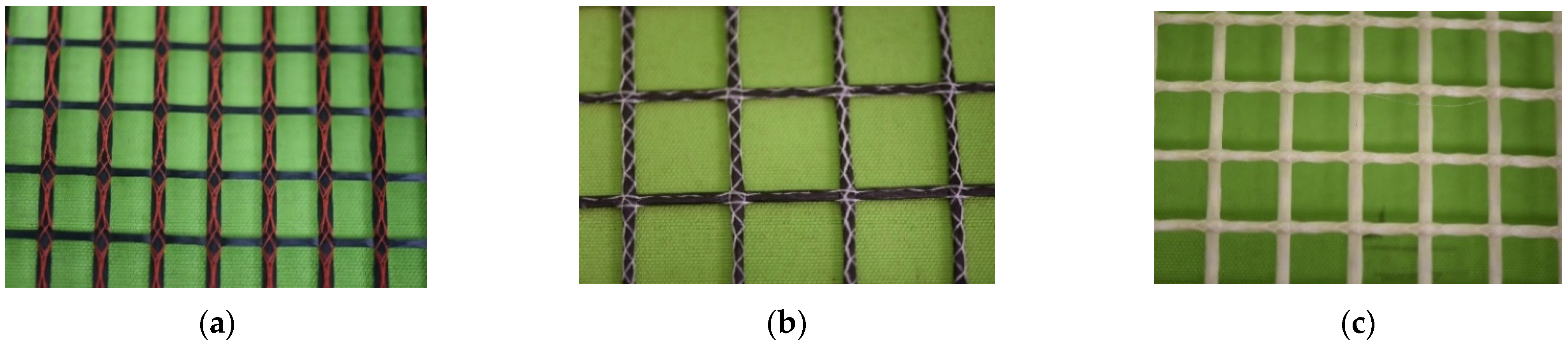
The Shore hardness according to ISO 868 [42] and ISO 48-4 [43] meets all these requirements but does not apply to fiber-reinforced plastics. The measuring method describes the penetration resistance of a metal tip when pressed into a material. The tip is pressed into the material with a defined force, and the penetration depth is measured. Thus, the hardness is a kind of Young’s modulus of the upper layer of the test specimen. The main research question addressed here is: Is the Shore hardness suitable for measuring the stiffness of impregnated fiber strands for use in TRC? For this purpose, Shore hardness tests and tensile tests on different sorts of fiber strands were conducted and analyzed. In addition, the results of the hardness tests were correlated to the bond tests performed in reference [36].

2.2. Materials

Several different textiles with varying materials and impregnation agents were considered for the Shore hardness and tensile testing. Most of the examined textiles were made of carbon, but one was AR–glass. The cross-section of the textiles ranged from 24 k to 144 k. The impregnation materials were acrylate (ACR), styrene–butadiene rubber (SBR) and epoxy resin (EP). For both the Shore hardness and tensile testing, 10–20 fiber strands were examined. The tested textiles (Figure 8 show exemplary textiles) had the following characteristics:
-
10 × 48 k carbon (8× ACR, 2× SBR).
-
1 × 4800 tex AR-glass (ACR).
-
1 × 144 k carbon (EP).
-
1 × 24 k carbon (ACR).

2.3. Testing Methods

Shore Hardness Testing

Shore hardness measures the hardness of elastomers by measuring the penetration depth. It is regulated by ISO 868 [42] and ISO 48-4 [43]. A distinction is made between Shore hardness A, D, AO and AM, which are used for different types of elastomers. For each of these measurements, there is a separate durometer that differs in terms of the applied force, the size of the pressure plate and the shape of the intender (Figure 9).
Here, the intender is in its starting position before testing. The intender is pushed out of the device by a spring with a defined spring force at all times. When testing, the intender is partially or fully pushed into the device, which directly results in the measurement. The Shore hardness ranges from 0 to 100 reflecting the degree of penetration. A Shore hardness of 0 means the intender did not move at all, so the tested material must be very soft, while a Shore hardness of 100 shows that the intender was fully submerged in the device, so the material must be very hard. The Shore hardness should always be measured for a specific amount of time because the length of the test might influence the results. The temperature and the size of the measured sample are also factors that could influence the outcome of the measurements.
To measure the transversal stiffness of fiber strands, first individual fiber strands are separated from the textile, ensuring the strands are not damaged in the process. Before testing, two other strands of the same textile are glued on to a 1 cm thick steel plate with a gap of about 1.5 cm between them (see Figure 10). The yarn that is going to be tested is put between the other two strands. This method improves on the pretests, where there was no stabilization for the Shore hardness measurement. It ensures a stable test setup in which the durometer does not tilt while testing, and there is always the same material underneath to minimize falsifications due to the test setup. The durometer used here is a handheld Shore D durometer, and the set measuring time is 15 s. The Shore D durometer has a defined spring force of 50 N ± 0.5 N [44]. For every textile, 10–20 fiber strands were tested.
The tensile strength was tested following fiber strand test type c (Figure 5). Figure 11 shows the test setup. To perform the tensile tests, a universal testing machine Inspekt 100 from Hegewald und Peschke (Germany) was used.
The strands that were previously separated from the textile had a total length of 470 mm, which resulted in a free expansion length of 320 mm and a clamping length of 150 mm in total. The clamping jaw inserts thus had a length of 75 mm each. The clamping jaw inserts were chosen to be this long in order to adapt the test setup to the textiles, which were sensitive to transverse pressure. If the jaws are very short, stress peaks may occur at the ends of the jaw inserts, causing textiles to fail prematurely. Furthermore, a special type of clamping jaw insert was developed to counter the occurrence of stress peaks in the clamping area. These inserts were made of an aluminum plate, a wood fiber plate and one layer of sandpaper with a grain size of 180. To secure the fiber strand, the clamping jaws are screwed shut with a defined torque of 12.5 Nm. The tests are path-controlled and start with an initial velocity of 1 mm/min until a preload of 150 N is reached. Then, the testing velocity is increased to 6 mm/min until the force drops by 90% and the test concludes.

3. Results

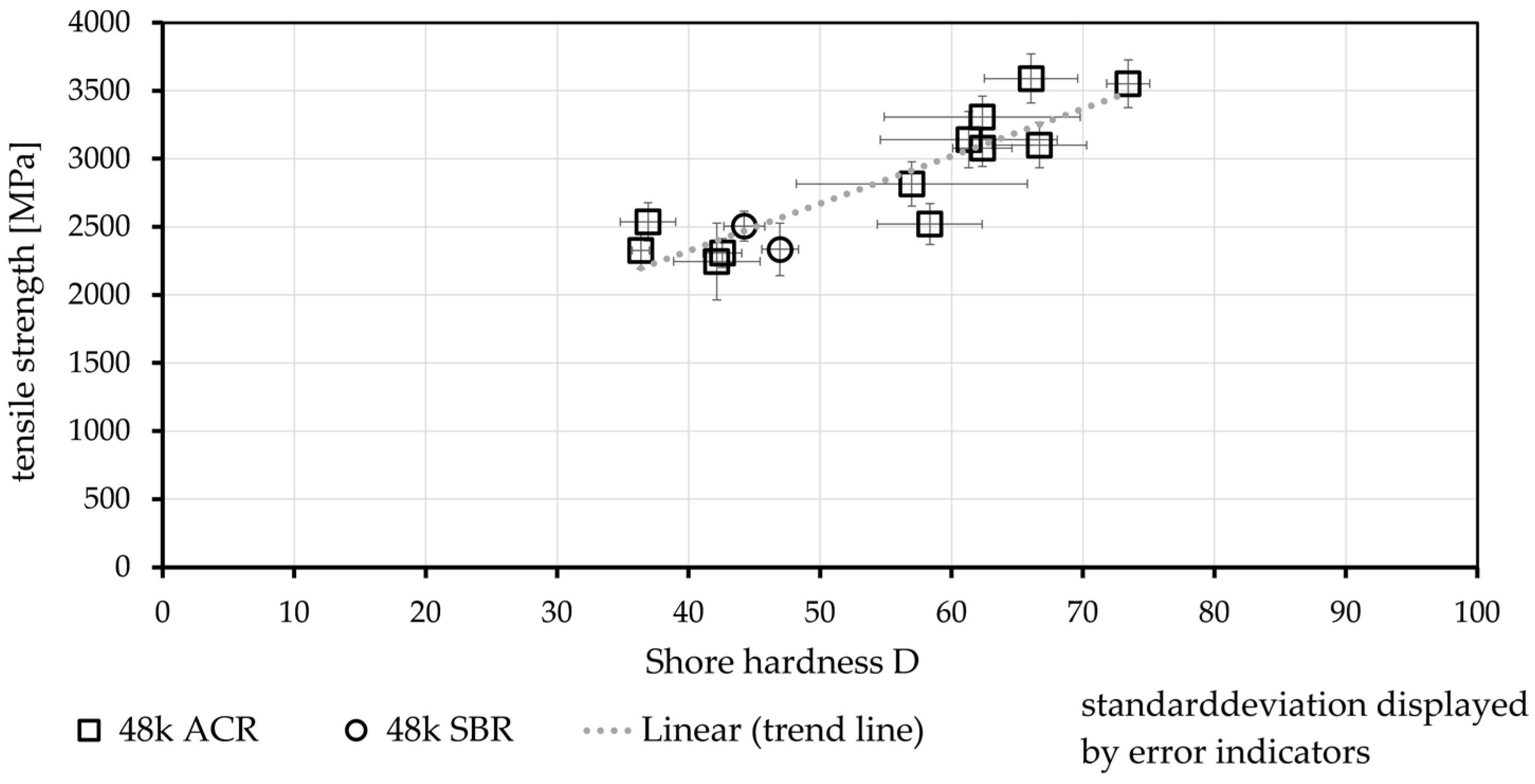
3.1. Relationship between Shore Hardness D and Tensile Strength

3.1.1. Varying Fiber Strands and Impregnation Materials

Figure 12 shows the Shore hardness D in relation to the tensile strength of a wide selection of textiles.
The tested textiles varied in terms of yarn material, yarn thickness and impregnation material, which in turn influence the Shore hardness. The left-most point in the diagram illustrates the only AR–glass textile that was tested, while the right-most point depicts the carbon textile with the biggest cross-section and epoxy resin impregnation. There is a clear trend that tensile strength increases with increasing Shore hardness. This indicates that there is a correlation between the Shore hardness and the tensile strength of the textile materials, and the regression line depicts this trend. However, predicting values outside of this range is not possible based on this trend line. It can be assumed that with increasing Shore hardness, the textiles have higher tensile strength, but the curve flattens out. Likewise, a flattening of the curve can be assumed in the lower value range. It can be assumed that the tensile strength converges towards the yarn tensile strength (unimpregnated) with decreasing hardness and towards a maximum possible tensile strength with increasing hardness. It is also important to note that the Shore hardness exhibits a rather large variance compared with the tensile strength.
In Figure 13, only 48 k carbon fiber strands were examined, and they show the same trend between the Shore hardness and the tensile strength. Consequently, the Shore hardness of the impregnation material must have a significant influence on the tensile strength, although categorizing the textiles according to Shore hardness remains difficult as the transitions are fluid. This is because all of the impregnation materials have a certain range of hardness. Generally, EP is considered hard and SBR is considered mostly soft. ACR has a much wider range of hardness, which can also be seen in Figure 13.

3.1.2. Quantifying the Stiffness of One Production Batch

One aspect that would be rather interesting for industry is whether the Shore hardness could be tested for the quality control of one production batch. To determine whether differences could also be detected regarding the same textile, several strands of the same textile were tested. However, no correlation could be detected (Figure 14). The Shore hardness therefore cannot be used for the quality control of individual strands of the same textile as the measurement is too inaccurate. The diagram also includes a histogram of the Shore hardness that shows that the hardness is almost evenly distributed.

3.1.3. Evaluation of the Different Textile Sections

Figure 15 shows the Shore hardness of the warp thread, the weft thread and the knot of the same textile. Both the warp thread and the weft thread have the same 24 k roving, which are also both knitted. It is obvious that the knots exhibit greater hardness than both yarns. One reason for this could be that the knots are compressed during the production process, which in turn leads to greater stiffness in this area.

3.2. Correlation between the Fiber Strand Stiffness and the Bond Performance

In References [35,36], investigations were conducted on the bond behavior of different textiles in combination with various concretes (compare also Figure 7). The textile (geometry 1 = T1) was tested in three different variants. The variants differed concerning the impregnation material (1 × SBR, 2 × ACR), the production batch (2 batches ACR impregnated) and the changes in the fiber strand cross-section. However, the yarn spacings (0° = 12.7 mm and 90° = 16.0 mm), the yarn type (48 k carbon roving) and the production process were identical for all three textiles. To investigate the influence of the transversal stiffness, the Shore hardness as well as the changes in the cross-section along the fiber strand were measured (compare [45]). Due to the compaction of the fiber strand at the knotting points, here, the fiber strand cross-section (width/thickness) is in general lower than the cross-section in the middle between two knots. The difference, e.g., for the width can be described by Δwidth = (widthmiddle − widthknot)/widthknot and indicated as a percentage. The results of the maximum bond flow (Tmax) (adapted from Reference [36] for C1), the Shore hardness (hardness) and the changes in the cross-section (Δ width and Δ thickness) are shown in Figure 16.
The diagram shows that the impregnation material has a huge impact on the bond performance (Tmax). While the SBR impregnation led to a Tmax of 11.0 N/mm, the maximum bond flow of the ACR-impregnated fiber strand was more than six times higher. The measured hardness ranged from 47 to 73. This means that the ACR was stiffer than the SBR by a factor of 1.55. Additionally, the changes in the yarn cross-section differed. Both ACR-impregnated textiles showed greater deltas. This also led to a higher bond flow. In addition to the yarn cross-section and its changes along the strand, the production process also influences the bond performance [33]. By assuming that the geometrical properties of all textiles are similar, a direct correlation between the bond performance (maximum bond flow Tmax) and the hardness is possible (see Figure 17).
The results can be mathematically described via a linear correlation (dashed line). This means that in the case of this textile, the bond strength can be directly deduced from the Shore hardness. The gradient of the dashed line is 2.3. Therefore, the bond performance increases disproportionately with increasing Shore hardness. However, the expressiveness of the results shown here is limited to one textile configuration with two different impregnation materials. Consequently, further investigations are needed to verify the general applicability of this relationship.

4. Discussion

The questions arise of whether the arrangement of the textile hardness in groups is practical and whether the hardness could be used to categorize stiffness. As seen in Figure 18, the categories could be defined as <50 (soft), 50–70 (medium stiff) and >70 (stiff). Although the transitions are fluid, categorization in these groups could lead to a quantitative assessment of the stiffness of impregnated fiber strands. This could possibly replace the rather vague differentiation of the impregnation agents as “hard” or “soft“ (compare [40]) without directly mentioning the exact material that has been used in production.
In Section 3.2, a correlation between the Shore hardness and the bond performance is shown. The changes in the cross-sectional dimensions are here assumed as constant because the investigated textiles produced were similar. As such, the results are valid for fiber strands with similar geometrical properties and different impregnation materials. The results are comparable with ReferenceS [17,38], in which the pullout force also increased with the increasing mechanical properties (Young’s modulus) of the impregnation material. In Reference [38], the end results are displayed, and the stiffness is described with high/low composite stiffness. In Reference [17], the mechanical properties (tensile strength and Young’s modulus) of the sole impregnation materials are described. A quantitative correlation between the mechanical properties and the tensile strength/bond performance of impregnated fiber strands is not detailed.
In References [45,46], fiber strands with different geometrical properties, but impregnated with an identical agent (EP), were investigated concerning the bond performance and splitting failure of the surrounding concrete. The result was a model for calculating the splitting tendency of a textile. As input parameters, the change in the cross-section along the fiber strand is necessary. The model is valid for the used impregnation material and variating cross-sectional dimensions. If the model is to be adapted to textiles with various impregnation materials, the stiffness of the agent is probably needed. One possibility would be to use the Shore hardness, which can also be seen as an elastic modulus of the outer part of the fiber strand.
To generalize the results shown here, more tests—especially for stiff impregnation agents (hardness > 70), e.g., epoxy resin—should be conducted. Using the model shown in [46] and introducing the hardness in a quantitative way, adapting the model for various impregnation agents could be possible.

5. Conclusions

Impregnating fiber strands for use in TRC serves to homogenize the tensions in the fiber strand cross-section and improve the bonding performance between textile and concrete. The properties of the impregnation material and the textile manufacturing process clearly influence the mechanical properties of the impregnated fiber strand. One important parameter is the transversal stiffness of the impregnated fiber strand. The measuring method (Shore hardness D) can be used to determine the hardness, which is a sort of a Young’s modulus, transversal to the fibers. The result is a quantitative description of the stiffness with only one value. The Shore hardness can be used for all kinds of impregnation materials while also considering the textile manufacturing process. The test setup according to ISO 48-4 or ISO 868 has to be slightly modified to improve the measurement.
Considering the aforementioned results, there is a clear correlation between the Shore hardness and the tensile strength of textiles. This could possibly be used to determine groups for characterizing the stiffness of impregnation agents. However, the Shore hardness does not seem to be suitable for quality control or for measuring differences in the same impregnation agent because the scatter of the tensile strength and the Shore hardness are too big. In case of the bond strength between textile and concrete, a clear dependency on shore hardness was seen for one textile in three different production batches (1×SBR, 2×ACR). Using these results and adding more studies, it could be possible to introduce the stiffness of the fiber strand to the models for describing the bond behavior of textiles embedded in concrete.

Author Contributions

Conceptualization, M.B.; Investigation, M.B. and L.M.; Writing—original draft, M.B. and L.M.; Writing—review & editing, M.B., L.M. and J.O.; Supervision, J.O.; Funding acquisition, J.O. All authors have read and agreed to the published version of the manuscript.

Funding

This research received no external funding.

Data Availability Statement

The data are available from the authors on request.

Acknowledgments

We would like to thank Hitexbau GmbH (Germany) especially Werner Sinz for providing technical textiles for our investigations. We also want to thank CHT Germany GmbH, especially Amon Klausmann and Ralf Schneppensiefen. They always supported our work with discussion and helpful advice.

Conflicts of Interest

The authors declare no conflict of interest.

References

  1. Peled, A.; Bentur, A.; Mobasher, B. Textile Reinforced Concrete; CRC Press: Boca Raton, FL, USA, 2017; ISBN 9781315119151. [Google Scholar]
  2. Beßling, M.; Groh, M.; Koch, V.; Auras, M.; Orlowsky, J.; Middendorf, B. Repair and Protection of Existing Steel-Reinforced Concrete Structures with High-Strength, Textile-Reinforced Mortars. Buildings 2022, 12, 1615. [Google Scholar] [CrossRef]
  3. Sydow, A.; Kurath, J.; Steiner, P. Extrem leichte Brücke aus vorgespanntem Carbonbeton: Fahrradbrücke über die Eulach im Winterhur/Schweiz aus vorgespanntem Carbonbeton. Beton- und Stahlbetonbau 2019, 114, 869–876. [Google Scholar] [CrossRef]
  4. Kulas, C.; Goralski, C. Die weltweit längste Textilbetonbrücke: Technische Details und Praxiserfahrungen. Beton- und Stahlbetonbau 2014, 109, 812–817. [Google Scholar] [CrossRef]
  5. Dey, V.; Zani, G.; Colombo, M.; Di Prisco, M.; Mobasher, B. Flexural impact response of textile-reinforced aerated concrete sandwich panels. Mater. Dec. 2015, 86, 187–197. [Google Scholar] [CrossRef]
  6. Shams, A.; Hegger, J.; Horstmann, M. An analytical model for sandwich panels made of textile-reinforced concrete. Constr. Build. Mater. 2014, 64, 451–459. [Google Scholar] [CrossRef]
  7. Heid, A.-C.; Stark, A.; Will, N.; Hegger, J. Weitspannende Sandwichelemente mit vorgespannten Textilbetondeckschichten und geschäumter Kernschicht. Beton- und Stahlbetonbau 2021, 116, 498–507. [Google Scholar] [CrossRef]
  8. Chira, A.; Kumar, A.; Vlach, T.; Laiblová, L.; Hajek, P. Textile-reinforced concrete facade panels with rigid foam core prisms. J. Sandw. Struct. Mater. 2016, 18, 200–214. [Google Scholar] [CrossRef]
  9. Beßling, M.; Antons, U.; Orlowsky, J. Potentials of Textile Reinforced Concrete for Lightweight Noise Protection Walls. In High Tech Concrete: Where Technology and Engineering Meet; Hordijk, D.A., Luković, M., Eds.; Springer International Publishing: Cham, Switzerland, 2018; pp. 2538–2545. ISBN 978-3-319-59470-5. [Google Scholar]
  10. Orlowsky, J.; Maurer, R.; Heeke, G.; Beßling, M.; Bettin, M. Ressourcenschonende Lärmschutzelemente aus Textilbeton als Alternative für konventionelle Stahlbetonfertigteile—Resource-saving noise protection elements made of textile reinforced concrete as an alternative for conventional precast reinforced concrete elements. Beton Stahlbetonbau 2021, 116, 947–957. [Google Scholar] [CrossRef]
  11. Brückner, A.; Ortlepp, R.; Curbach, M. Textile reinforced concrete for strengthening in bending and shear. Mater. Struct. 2006, 39, 741–748. [Google Scholar] [CrossRef]
  12. Koutas, L.N.; Tetta, Z.; Bournas, D.A.; Triantafillou, T.C. Strengthening of Concrete Structures with Textile Reinforced Mortars: State-of-the-Art Review. J. Compos. Constr. 2019, 23, 882. [Google Scholar] [CrossRef]
  13. Morales Cruz, C. Crack-distributing Carbon Textile Reinforced Concrete Protection Layers. Ph.D. Thesis, RWTH Aachen, Aachen, Germany, 2020. [Google Scholar]
  14. Reichenbach, S.; Preinstorfer, P.; Hammerl, M.; Kromoser, B. A review on embedded fibre-reinforced polymer reinforcement in structural concrete in Europe. Constr. Build. Mater. 2021, 307, 124946. [Google Scholar] [CrossRef]
  15. Cherif, C. Textile Werkstoffe für den Leichtbau. In Techniken–Verfahren–Materialien–Eigenschaften; Springer: Berlin/Heidelberg, Germany, 2011; ISBN 3642179916. [Google Scholar]
  16. Brameshuber, W. Textile Reinforced Concrete. State-of-the-Art report of RILEM Technical Committee 201-TRC; RILEM Publications S.A.R.L.: Bagneux, France, 2006; ISBN 2-912143-99-3. [Google Scholar]
  17. Schleser, M. Einsatz Polymerimprägnierter, Alkaliresistenter Glastextilien zur Bewehrung Zementgebundener Matrices. Phd Thesis, RWTH Aachen, Aachen, Germany, 2008. [Google Scholar]
  18. Kulas, C. Zum Tragverhalten Getränkter Textiler Bewehrungselemente für Betonbauteile. Ph.D. Thesis, RWTH Aachen, Aachen, Germany, 2013. [Google Scholar]
  19. Orlowsky, J.; Raupach, M. Durability model for AR-glass fibres in textile reinforced concrete. Mater. Struct. 2008, 41, 1225–1233. [Google Scholar] [CrossRef]
  20. van Itterbeeck, P.; Purnell, P.; Cuypers, H.; Tysmans, T.; Orlowsky, J.; Wastiels, J. Durability models for GRC: Uncertainties on strength predictions. Plast. Rubber Compos. 2012, 41, 77–87. [Google Scholar] [CrossRef]
  21. Hempel, S.; Butler, M.; Mechtcherine, V. Durability of textile reinforced concrete made with AR glass fibre: Effect of the matrix composition. Mater. Structures. 2010, 43, 1351–1368. [Google Scholar] [CrossRef]
  22. Büttner, T.; Orlowsky, J.; Raupach, M. Erhöhung der Dauerhaftigkeit textiler Beton-Bewehrungen durch Epoxidharztränkung. Bautechnik 2011, 88, 263–270. [Google Scholar] [CrossRef]
  23. Lenting, M.; Orlowsky, J. Einaxiale Zugversuche an textilbewehrten Betonen mit anorganisch getränkten Carbonfasern—Uniaxial tensile tests in textile reinforced concretes with inorganic impregnated carbon fibres. Beton Stahlbetonbau 2019, 115, 495–503. [Google Scholar] [CrossRef]
  24. Schneider, K.; Michel, A.; Liebscher, M.; Mechtcherine, V. Verbundverhalten mineralisch gebundener und polymergebundener Bewehrungsstrukturen aus Carbonfasern bei Temperaturen bis 500 °C. Beton Stahlbetonbau 2018, 113, 72. [Google Scholar] [CrossRef]
  25. Heppes, O. Von der Idee zur industriellen Produktion von Parkhausdeckenplatten mit Carbonbeton. Ph.D. Thesis, Technische Universität Kaiserslautern, Kaiserslautern, Germany, 2021. [Google Scholar]
  26. ISO 3341; International Organization for Standardization–ISO–Textile Glass—Yarns—Determination of Breaking Force and Breaking Elongation. Beuth Verlag GmbH: Berlin, Germany, 2000.
  27. ISO 10618; Normenausschuss Kunststoffe (FNK) im DIN. Carbon Fibre Determination of Tensile Properties of Resinrimpregnated yarn (ISO 10618:2004). German Version EN:2004; Beuth Verlag GmbH: Berlin, Germany, 2004.
  28. Rempel, S.; Ricker, M. Ermittlung der Materialkennwerte der Bewehrung für die Bemessung von textilbewehrten Bauteilen. Bauingenieur 2017, 92, 280–287. [Google Scholar] [CrossRef]
  29. Rempel, S. Zur Zuverlässigkeit der Bemessung von Biegebeanspruchten Betonbauteilen Mit Textiler Bewehrung. Ph.D. Thesis, Universitätsbibliothek der RWTH Aachen, Aachen, Germany, 2018. [Google Scholar]
  30. Hinzen, M. Prüfmethode zur Ermittlung des Zugtragverhaltens von textiler Bewehrung für Beton. Bauingenieur 2017, 289–291. [Google Scholar] [CrossRef]
  31. Lorenz, E.; Schütze, E.; Schladitz, F.; Curbach, M. Textilbeton- Grundlegende Untersuchungen im Überblick. Beton Stahlbetonbau 2013, 108, 711–722. [Google Scholar] [CrossRef]
  32. Schütze, E.; Bielak, J.; Scheerer, S.; Hegger, J.; Curbach, M. Einaxialer Zugversuch für Carbonbeton mit textiler Bewehrung—Uniaxial tensile test for carbon reinforced concrete with textile reinforcement. Beton Stahlbetonbau 2018, 113, 33–47. [Google Scholar] [CrossRef]
  33. Lorenz, E. Endverankerung und Übergreifung textiler Bewehrungen in Betonmatrices. Ph.D. Thesis, Technische Universität Dresden, Dresden, Germany, 2014. [Google Scholar]
  34. Bielak, J.; Spelter, A.; Will, N.; Claßen, M. Verankerungsverhalten textiler Bewehrungen in dünnen Betonbauteilen—Anchorage behavior of textile reinforcement in thin concrete components. Beton- und Stahlbetonbau 2018, 113, 515–524. [Google Scholar] [CrossRef]
  35. Beßling, M.; Orlowsky, J. Textile reinforced concrete—Analysis of cracking along the fiber strand in concreteB. In Bond in Concrete—Bond, Anchorage, Detailing, Proceedings of the 5th International Conference, Stuttgart, Germany, 25–27 July 2022; Hofmann, J., Plizzari, G., Eds.; Universität Stuttgart: Stuttgart, Germany, 2022; pp. 932–944. [Google Scholar]
  36. Beßling, M.; Orlowsky, J. Quantification of the Influence of Concrete Width per Fiber Strand on the Splitting Crack Failure of Textile Reinforced Concrete (TRC). Polymers 2022, 14, 489. [Google Scholar] [CrossRef]
  37. ISO 527; Deutsches Institut für Normung e.V. Plastics—Determination of tensile properties. German version of EN. 83.080.01 (DIN EN ISO 527 part 1–3). Beuth Verlag GmbH: Berlin, Germany, 2019.
  38. Glowania, M.; Gries, T.; Schoene, J.; Schleser, M.; Reisgen, U. Innovative Coating Technology for Textile Reinforcements of Concrete Applications. KEM 2011, 466, 167–173. [Google Scholar] [CrossRef]
  39. Niederwald, M. Einfluss des Beschichtungsmaterials auf das Zugtragverhalten von Carbonbeton. Beton Stahlbetonbau 2017, 112, 637–645. [Google Scholar] [CrossRef]
  40. Preinstorfer, P.; Kromoser, B.; Kollegger, J. Categorisation of the bond behaviour of textile reinforced concrete. Bauingenieur 2019, 94, 416–424. [Google Scholar] [CrossRef]
  41. Preinstorfer, P.; Kollegger, J. New insights into the splitting failure of textile-reinforced concrete. Compos. Struct. 2020, 243, 112203. [Google Scholar] [CrossRef]
  42. ISO 868; Deutsches Institut für Normung e.V. DIN EN ISO 868: Plastics and ebonite—Determination of indentation hardness by means of a durometer (Shore hardness) (ISO 868:2003). German Version EN:2003. 83.060; 83.080.01 (DIN EN ISO 868). Beuth Verlag GmbH: Berlin, Germany, 2003.
  43. ISO48-4; DIN-Normenausschuss Materialprüfung. DIN ISO 48-4 Rubber, vulcanized or thermoplastic—Determination of hardness—Part4: Indentation hardness by durometer method (Shore hardness) (German version of 2018). Beuth Verlag GmbH: Berlin, Germany, 2018.
  44. Weißbach, W.; Dahms, M.; Jaroschek, C. Werkstoffprüfung. Werkstoffe und Ihre Anwendungen: Metalle, Kunststoffe und Mehr, 20., Überarbeitete Auflage; Springer: Wiesbaden, Germany, 2018; pp. 503–571. ISBN 9783658198923. [Google Scholar]
  45. Preinstorfer, P.; Kromoser, B. Influence of geometrical parameters on the splitting forces in textile-reinforced concrete. Mater. Struct. 2020, 53, 1590. [Google Scholar] [CrossRef]
  46. Preinstorfer, P. Zur Spaltrissbildung von Textilbewehrtem Beton: On the Splitting Behaviour of Textile Reinforced Concrete. Ph.D. Thesis, TU Wien, Wien, Austria, 2019. [Google Scholar]
Figure 1. Stress distribution in the cross-section of fiber strands embedded in concrete with different degrees of impregnation, adapted from [15].
Buildings 12 02038 g001
Figure 2. Details of yarns made of carbon: (a) incompletely impregnated yarn strand (cross-section), (b) fiber cracks due to the manufacturing process.
Buildings 12 02038 g002
Figure 3. Bridging of filament breaks through the impregnating agent, adapted from [18].
Buildings 12 02038 g003
Figure 4. Tensile strengths of exemplary impregnated fiber strands made of carbon fibers (48 k strands); results adapted from [10,25]; stiffness quantitively described concerning the mechanical properties (compare Table 2).
Buildings 12 02038 g004
Figure 5. Test setups for testing the tensile strength of fiber strands: (a) fixing reels for soft impregnated strands; (b) strand with epoxy resin blocks for load introduction; (c) clamps with increasing clamping pressure.
Buildings 12 02038 g005
Figure 6. Impregnated textile embedded in fine grained concrete.
Buildings 12 02038 g006
Figure 7. Influence of the yarn and concrete characteristics on the maximum bond flow tested in a single-sided pullout test: (a) textile geometries T1, T1b and T2; impregnation agents: A = acrylate, B = SBR; concretes C1 (fc,m = 100 MPa) and C2 (fc,m = 130 MPa); (b) tests performed with T2A and various concretes, adapted from [35,36].
Buildings 12 02038 g007
Figure 8. Photos of different textiles: (a) carbon textile, (b) carbon textile, (c) AR–glass textile.
Buildings 12 02038 g008
Figure 9. Shore D durometer according to [43], (a) shore D durometer, (b) detail of the pressure plate.
Buildings 12 02038 g009
Figure 10. (a) Close-up schematic of the Shore hardness testing. (b) One fiber strand fixed on the steel plate for testing.
Buildings 12 02038 g010
Figure 11. Test setup for testing the tensile strength of fiber strands, (a) drawing, (b) in the laboratory.
Buildings 12 02038 g011
Figure 12. Correlation between Shore hardness and tensile strength of textiles with varying cross sections, yarn materials and impregnation agents (mean values of 10–20).
Buildings 12 02038 g012
Figure 13. Correlation between Shore hardness and tensile strength of 48 k carbon textiles with varying impregnation agents (means values of 10–20).
Buildings 12 02038 g013
Figure 14. Shore hardness and tensile strength of one production batch and histogram of Shore hardness (means: 10–20).
Buildings 12 02038 g014
Figure 15. Influence of the textile section on the Shore hardness (mean values of 10 single values).
Buildings 12 02038 g015
Figure 16. Results (means) of the measurements of bond strength Tmax (6 single values) adapted from Reference [36], Shore hardness D (10 single values) and the changes in the yarn cross-section Δ width and Δ thickness (36 single values).
Buildings 12 02038 g016
Figure 17. Correlation between maximum bond flow (Tmax) and shore hardness, mean values of 6 (Tmax) and 10 (hardness) single values, standard deviation indicated.
Buildings 12 02038 g017
Figure 18. Categorization of the impregnation agents by hardness, <50 = soft, 50–70 = medium stiff, >70 = stiff.
Buildings 12 02038 g018
Table 1. Characteristics of the fiber raw materials (axial) [15].
MaterialTensile Strength [MPa]E-Modulus [GPa]
AR-glass300073
basalt2000–484089
carbon1750–7000200–500
Table 2. Mechanical characteristics of impregnation agents (polymers), adapted from [14].
MaterialTensile Young’s Modulus [GPa]Tensile Strength [MPa]
Styrene–butadiene3.0–3.43.5–20.5
Acrylate dispersion3.1–3.360–80
Epoxy resinup to 4.2up to 100
Publisher’s Note: MDPI stays neutral with regard to jurisdictional claims in published maps and institutional affiliations.

