Article

Effects of Openings and Axial Load Ratio on the Lateral Capacity of Steel-Fiber-Reinforced Concrete Shear Walls

1
College of Civil Engineering and Architecture, Zhejiang University, Hangzhou 310058, China
2
Department of Structural Engineering and Geotechnics, Sapienza University of Rome, 00197 Rome, Italy
3
Department of Civil, Construction-Architectural and Environmental Engineering, University of L’Aquila, 67100 L’Aquila, Italy
*
Author to whom correspondence should be addressed.
Buildings 2022, 12(11), 2032; https://doi.org/10.3390/buildings12112032
Submission received: 8 October 2022 / Revised: 1 November 2022 / Accepted: 10 November 2022 / Published: 21 November 2022
(This article belongs to the Special Issue High-Performance Concrete Structures for Disaster Prevention)

Abstract

:
Shear walls are commonly adopted as main structural members to resist vertical and lateral forces, thanks to their high load capacity and high lateral stiffness. However, their lateral capacity can be impaired in the presence of openings, which can reduce their lateral load capacity and stiffness. A possible solution is to cast shear walls using steel-fiber-reinforced concrete (SFRC), which effectively improves the deformation capacity of shear walls. However, few studies deal with the performance of such SFRC shear walls in the presence of openings. Moreover, the effect of different axial load ratios (ALR) is still not fully known. To study these essential parameters, a detailed Finite Element model has been implemented in ABAQUS. Having validated its accuracy against experimental tests on four SFRC shear walls, with and without openings, it has been subsequently used in a parametric study to analyze the effects of different ALRs, of different opening configurations, and of different reinforcement ratios. It is shown that door openings have a more detrimental effect on the lateral load capacity than window openings and that higher ALR values switch the prevailing failure mechanism from flexural to shear, thus reducing both ductility and deformation capacity.

Graphical Abstract

1. Introduction

Shear walls are the main structural members to resist vertical and lateral forces in high-rise buildings in seismic zones, thanks to their high vertical load capacity and high lateral stiffness and resistance. An important parameter affecting the lateral load and deformation capacity of shear walls is the axial load ratio (ALR) [1,2,3,4]. Shear walls at the lower stories of high-rise buildings have relatively high axial load ratio (ALR), which may induce significant damage when combined with horizontal earthquake forces. Particularly, concrete at the bottom corners can be easily crushed under seismic conditions [5]. Typically, shear walls are endowed with doors and windows, which often cause stress concentration around the openings [6]. Moreover, shear walls show a brittle behavior, mainly due to the low tensile strength of concrete. In this respect, several studies [4,7,8,9,10] demonstrate that the addition of steel fibers can improve the tensile strength of concrete, and show that shear walls cast using steel-fiber-reinforced concrete (SFRC) exhibit a better deformation capacity. While, in general terms, the adoption of SFRC may be beneficial for the overall behavior of shear walls, it is still unclear how this can be affected, both by the presence of openings and by high ALR.
Useful insight on these issues can be gained from the literature studies referring to different opening configurations. For example, Zhang et al. [11] conducted experimental and numerical studies on shear walls, proving that openings have significant influence on their performance under lateral loads. Popescu et al. [12] reported three experimental programs on RC shear walls with different opening configurations, which indicate that the presence of 25–50% openings produces 36–50% degradation on lateral bearing capacity, respectively. Experimental tests on four slender shear walls by Massone et al. [13] indicate that openings with 15–30% of the wall length and with 11–22% of the wall height do not significantly affect the lateral load capacity of slender walls (in those tests, the overall walls size was 2650 mm high, 900 mm wide, and 150 mm thick). Other studies investigated the influence, under cyclic loading, of openings size and position and shear wall height-to-width ratio. For example, an experimental study by Wang et al. [14] shows that, in case of eccentric opening locations, the load capacity depends on the loading direction. Hosseini et al. [6] investigated the structural performance of RC shear walls with different eccentric openings, showing that differences in the load capacity occurred under both push and pull loading directions, these differences at peak load being about 2%, 6.2%, and 12.5%, respectively. However, they did not identify possible reasons for these differences, such as the influence of steel fiber and reinforcement ratios. Another parameter having a critical role in the lateral capacity of RC shear walls is ALR. Su et al. [3] investigated the effect of ALR on shear walls and concluded that ALR not only affects failure mode but also rotation ductility, strength degradation, and energy dissipation. Alarcon et al. [2] also found that high ALR has a significant effect on the lateral capacity and failure mode of RC walls. An experimental study on cantilever wall specimens and corresponding numerical analysis by Dashti et al. [15] revealed that the effects of ALR on RC structures are complex because it can easily change the failure mode, e.g., from flexure to shear or flexure–out-of-plane to flexure–concrete crushing, and it highly depends on other parameters such as the shear–span ratio. A wide range of investigations has been carried out concerning the effect of ALR on RC shear walls, but there are few studies on SFRC shear walls with ALR, in view of the improvement of concrete tensile strength by steel fiber, the effect of ALRs on SFRC walls is still not clear.
An overview of these studies is given in Table 1, where it can be observed that there exist a wide range of investigations concerning the effect of both openings and ALR on RC walls, but also that there are relatively few studies dealing with the role of openings in SFRC shear walls under variable ALR. Since SFRC can improve the overall response with respect to traditional concrete, it is essential to perform some studies aimed at clarifying such aspects. This study brings a contribution in filling this research gap. The methodology adopted foresees to set up four finite element (FE) models representing the four SFRC shear walls tested by Huang [16]. Subsequently, after having calibrated these FE models against those experimental results and having assessed their accuracy, the models were modified by changing the openings configuration, the ALR, and the reinforcement ratio, so to explore other situations not considered in the original experimental study.
The main outcomes of this study can be summarized as follows: (1) a practical SFRC constitutive law has been compiled from a series of studies, which can capture the stress–strain relationship of SFRC in compression and in tension, (2) a detailed and accurate FE model has been implemented in ABAQUS, which can be used as a basis for further parametric studies, (3) the main parameters affecting the lateral capacity of SFRC shear walls have been identified, e.g., openings, ALR, and reinforcement ratio, (4) a matrix is proposed to classify failure modes in SFRC shear walls, and (5) a design scheme is proposed, accounting for the presence of window and door openings.

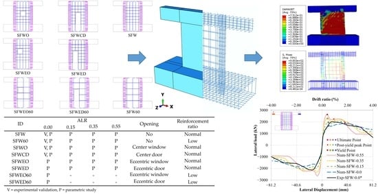
2. Finite Element Models Used in the Parametric Study

The parametric study presented in the following section has been performed by means of a set of finite element (FE) models, developed in ABAQUS. These models have been chosen to have the same geometry, detailing, and material properties as the specimens of a series of tests conducted by Huang [16]. After some sensitivity analyses, they have been calibrated so to accurately reproduce those experimental results. Once their accuracy has been ascertained, these models have been used in the parametric study to assess the effects of eccentric openings and different ALR values, including a case with eccentric opening and low reinforcement ratio. In this section, details regarding the FE model are given, while the parametric study is presented in the following chapter.

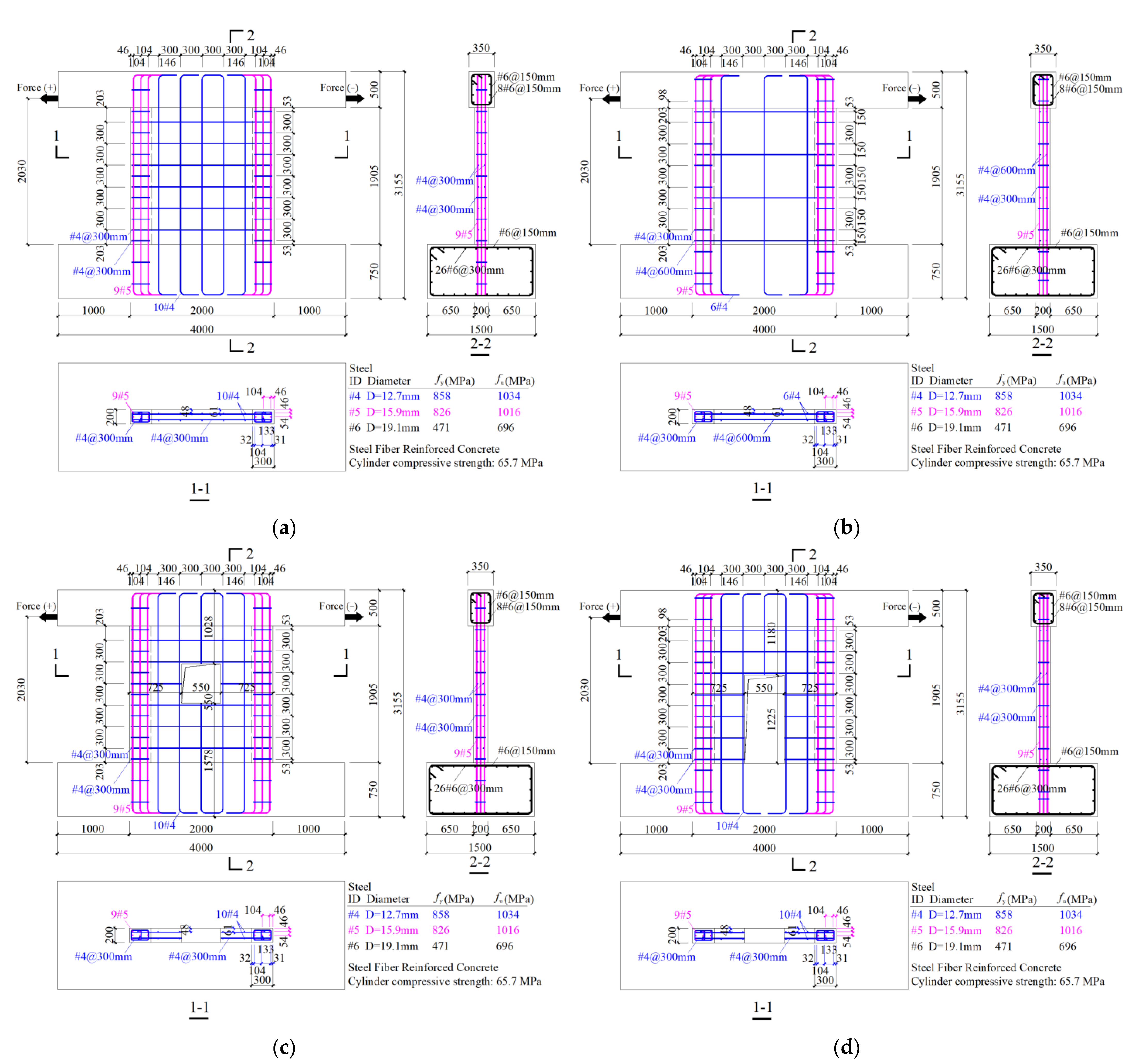
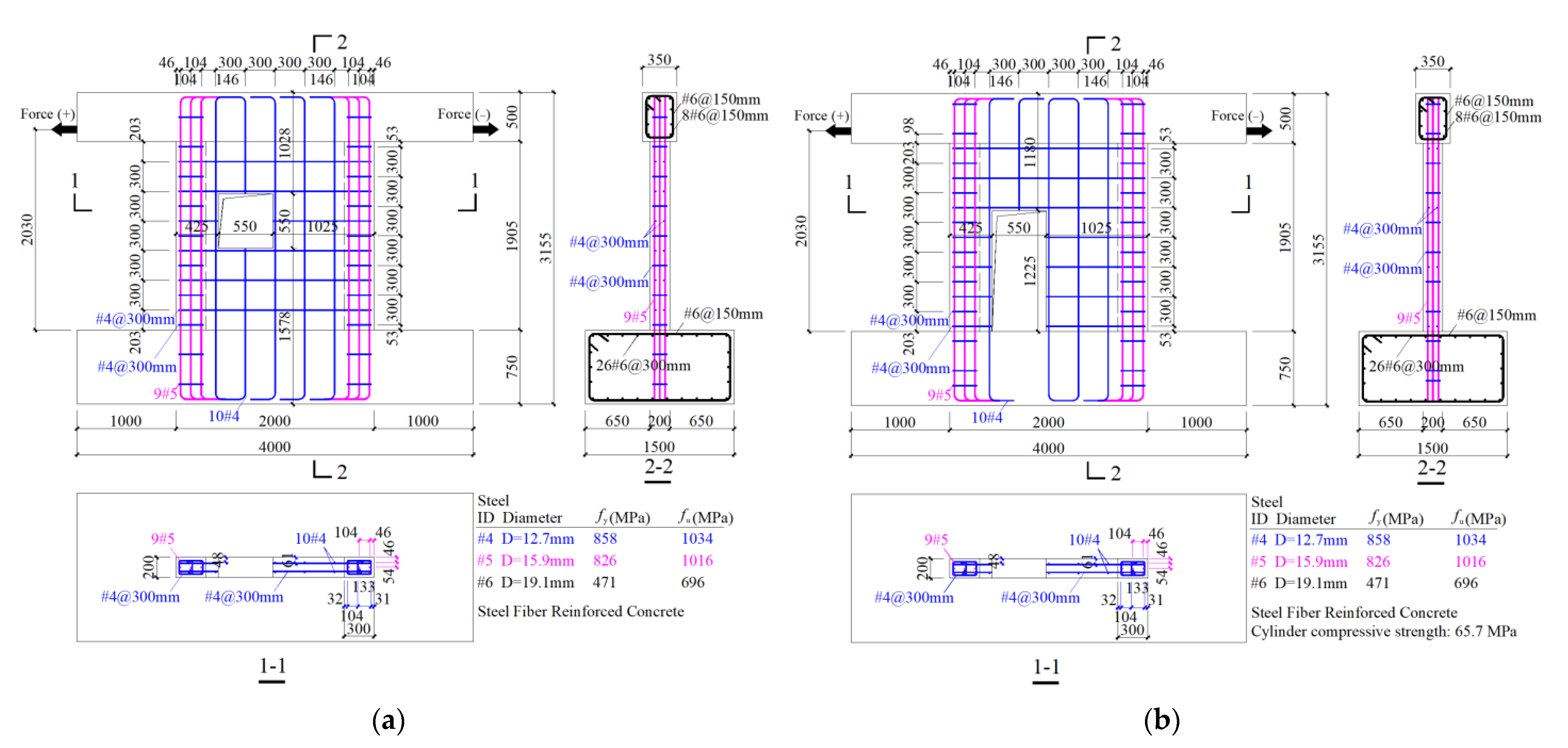
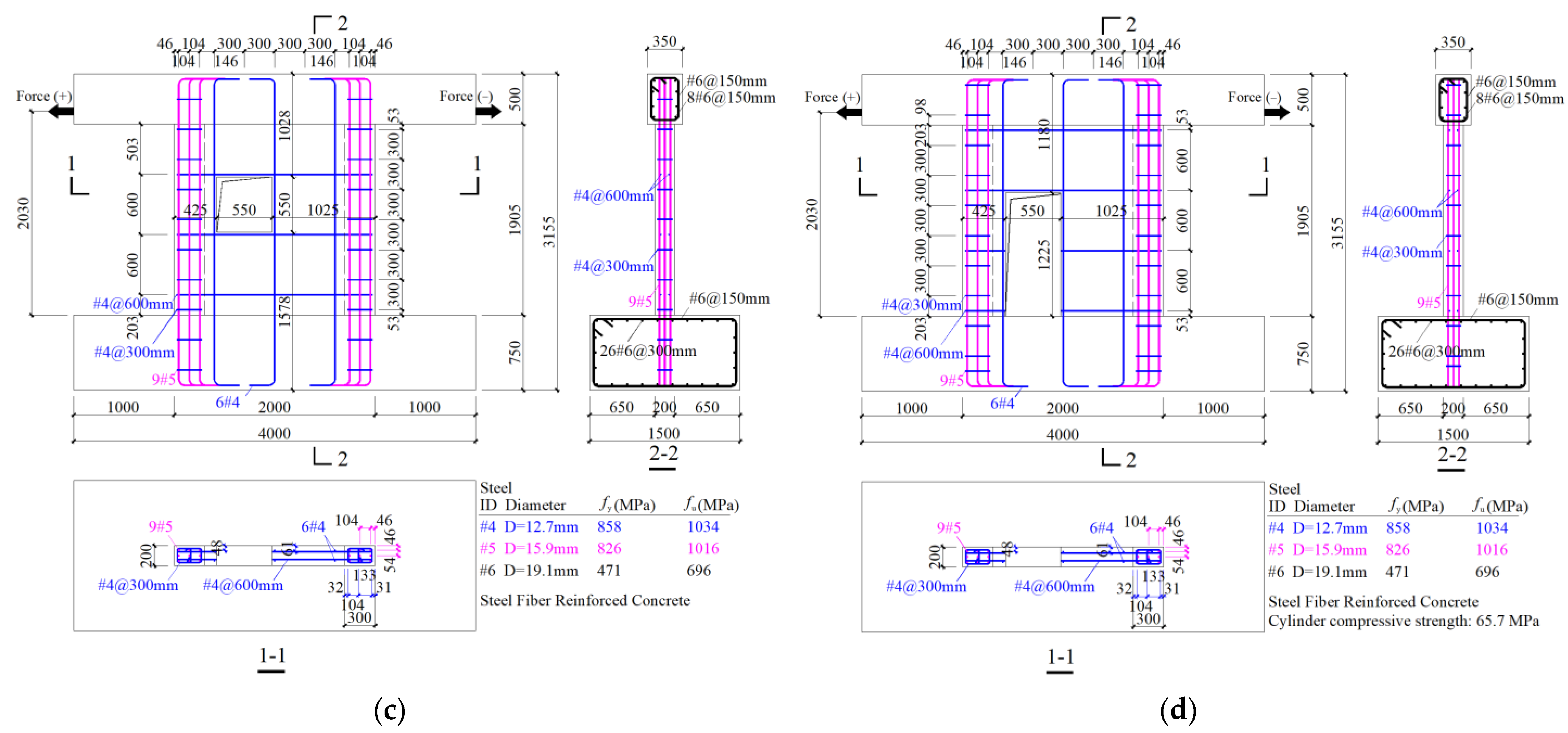
2.1. Tests Conducted by Huang [16]

Huang [16] conducted a series of tests on four different SFRC shear walls, all under ALR = 0. Each specimen consisted of a base beam, a wall, with or without opening, and a top beam. The detailed geometry and reinforcement of the reference specimens are shown in Figure 1, while the material constitutive laws are presented in the following section.

2.2. SFRC Constitutive Law

2.2.1. Uniaxial Compression Stress-Strain Relationship

Cylindrical compressive strength f c , c y l of SFRC with hooked-end steel fibers can be obtained either directly from 150 × 300 mm cylinder tests or, if 150 × 150 × 150 mm cubic compressive strength f c u is available, from:
f c , c y l = { 0.83 f c u f c u 10 30   MPa f c u 50   MPa 50   MPa   <   f c u 90   MPa
Some parameters describing the SFRC used in this study are listed in Table 2.
From these parameters, the fiber reinforcement index is defined as:
R I = V f l f d f
Extensive experimental and analytical studies on SFRC have been carried out [8,9,37,38,39,40,41,42,43]. In [9] a comparison study is reported of different stress-strain equations proposed in the literature, validated versus experimental stress-strain curves. It was found that the one proposed in [38] shows a good agreement and is therefore adopted here, with a slight modification of the elastic stage, as follows:
ε 0 = ( 0.0003 R I + 0.0018 ) f c , c y l 0.12
E c = ( 367 R I + 5520 ) f c , c y l 0.41
σ c = { ε c E c ε c / ε 0 < 1 / 3 f c , c y l A ( ε c / ε 0 ) A 1 + ( ε c / ε 0 ) B ε c / ε 0 1 / 3
A = { B = ε 0 E c ε 0 E c f c , c y l ε c / ε 0 1 1 + 0.723 R I 0.957 ε c / ε 0 > 1
B = max { ( f c , c y l 50 ) 0.064 ( 1 + 0.882 R I 0.882 ) , A } ε c / ε 0 > 1
where ε 0 is the strain at compressive strength, and E c is the undamaged elastic modulus.

2.2.2. Uniaxial Tension Stress-Strain Relationship

The tensile strength of concrete is estimated as:
f t = 0.56 f c , c y l 0.5
The tensile stress-strain relationship of steel-fiber-reinforced concrete developed by [37] is adopted here:
σ t = ( 1 d ) E c ( ε t ε p l )
d = { 0 a + b e c ε t × 10 6 ε t ε t u ε t > ε t u
a = 1 0.226 R I
b = 1 + 0.238 R I
c = 0.001 + 0.242 e 10 R I
ε p l = { 0 0.987 ε t 78.291 10 6 ε t ε t u ε t > ε t u
ε t u = f t E c
where ε p l and ε t u are the plastic strain and the strain corresponding to the tensile strength, respectively.

2.3. Reinforcing Bars Constitutive Law

The reinforcing bars are described by a typical elastic-plastic stress-strain law, whose parameters are listed in Table 3.

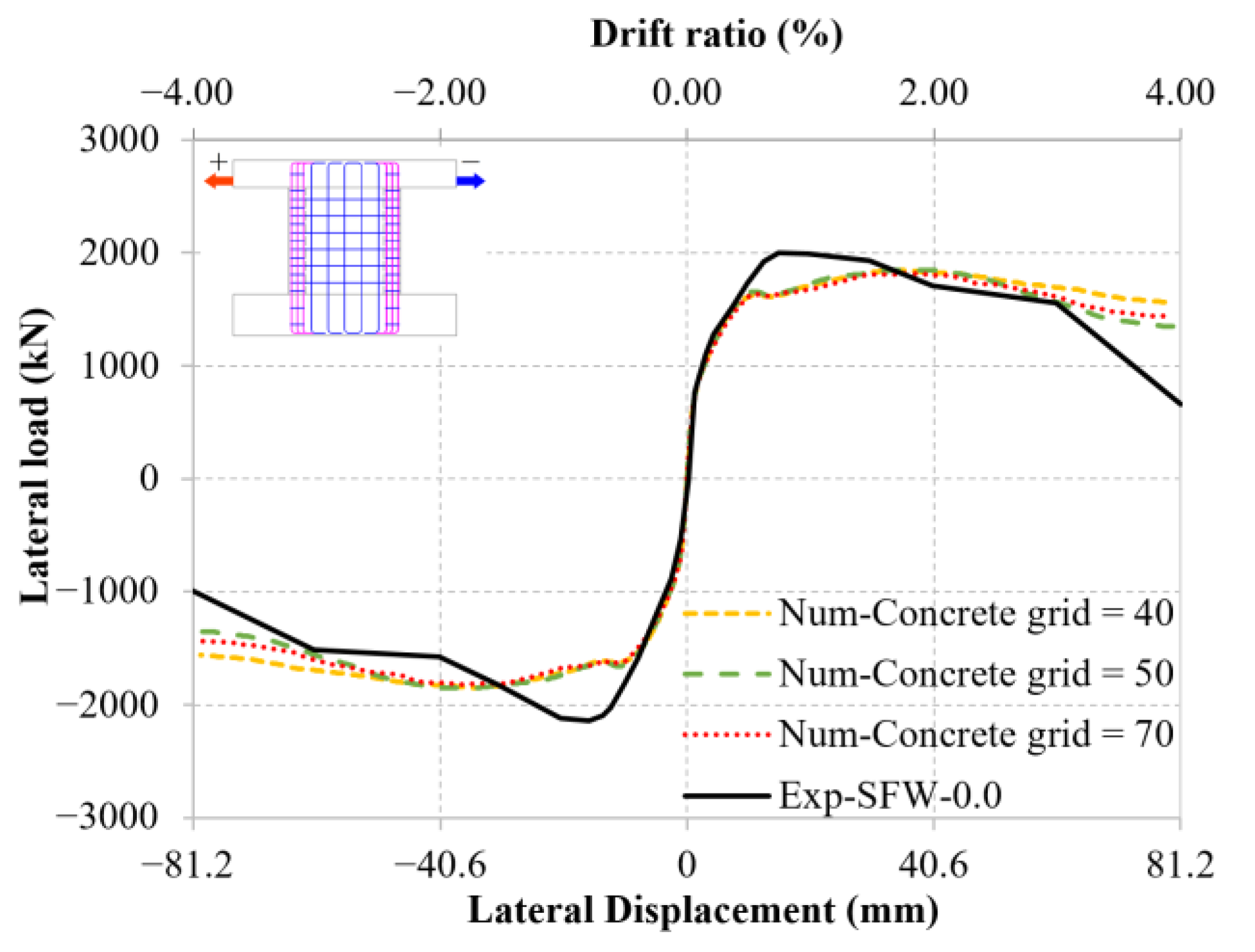
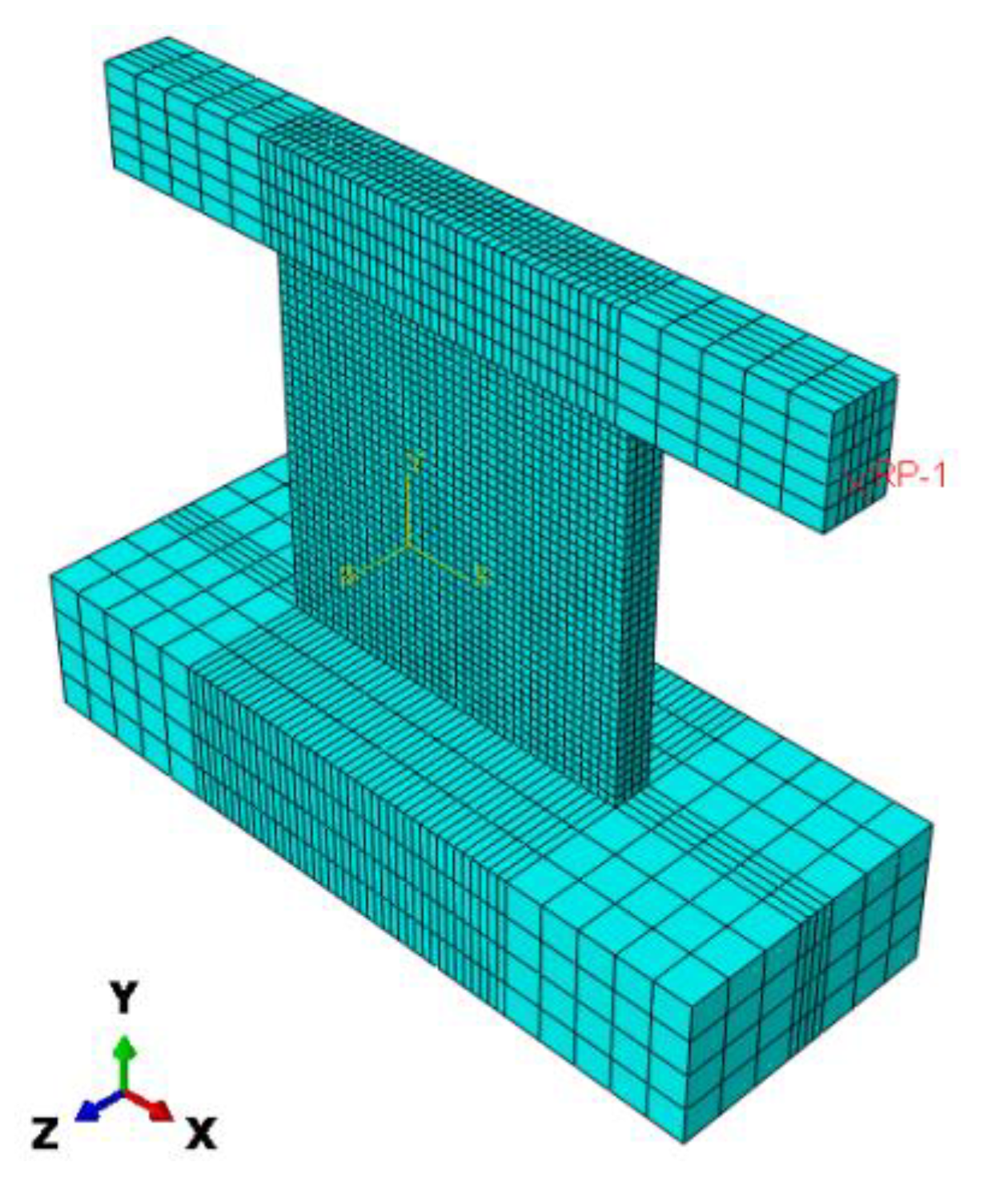
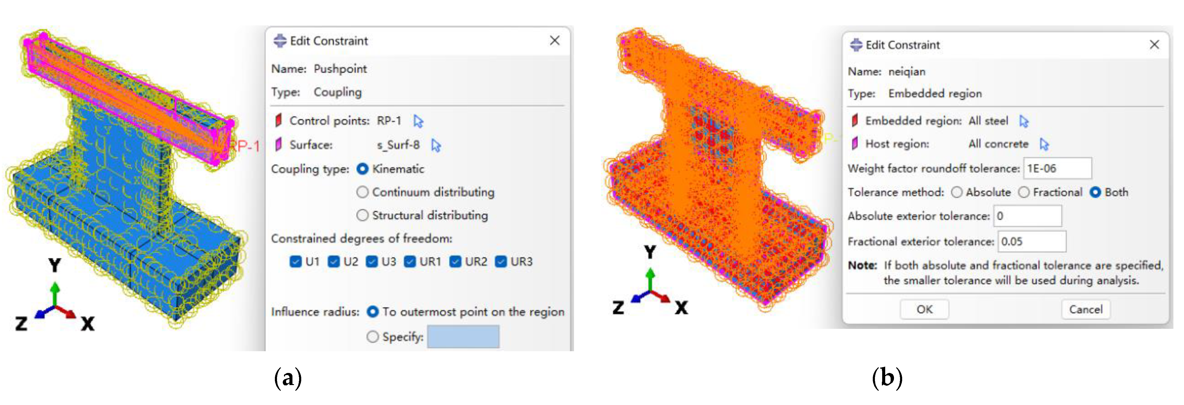
2.4. Finite Element Type and Mesh

The SFRC is modeled with solid elements (C3D8R), along with a Concrete Damage Plasticity (CDP) Model. A variety of damage parameters proposed in [44,45,46,47,48,49,50] were examined and, after comparing their relative accuracy, those used in [46] were selected. The adopted damage variables, D c and D t , vary between 0 (undamaged) and 1 (fully damaged), as follows:
D c = 1 σ c 0.2 ε c i n E c + σ c
D t = 1 σ t f t
ε c i n = ε c σ c E c
ε t c k = ε t σ t E c
where ε c i n is the inelastic strain, ε c c k is the cracking strain, and E c is the undamaged elastic modulus. Additional parameters of the CDP model are in Table 4.
The optimal mesh was selected after a comparison among three different concrete grids (Table 5) in terms of crack pattern (Figure 2) and load-displacement curve (Figure 3). The selected mesh (concrete grid = 50), shown in Figure 4 and Table 6, is a reasonable compromise between accuracy and computational time. These conclusions also apply to the models of the other three walls, whose comparisons in terms of load–displacement curves are not shown in this section for the sake of space. However, they can be found in the next section, within the parametric analyses.

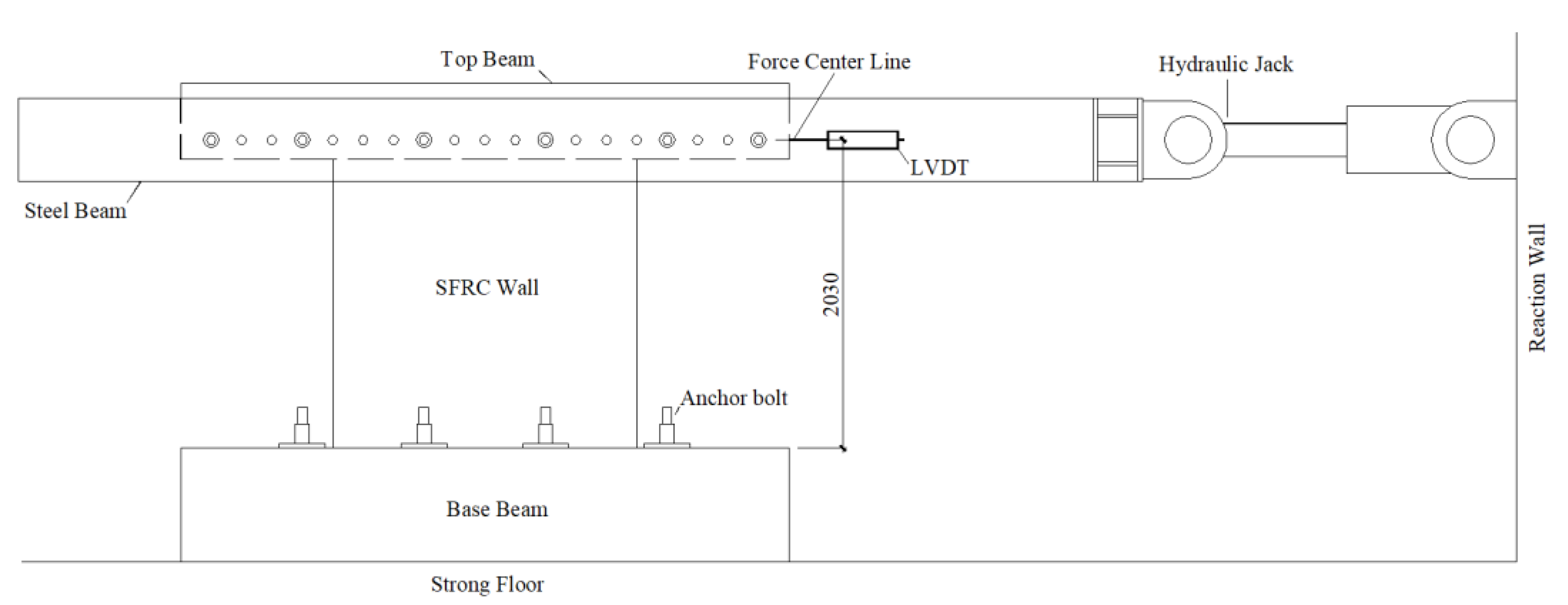
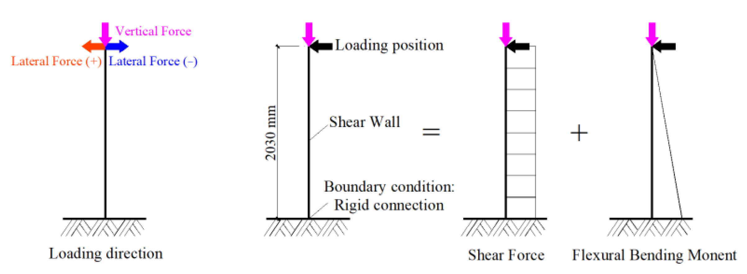
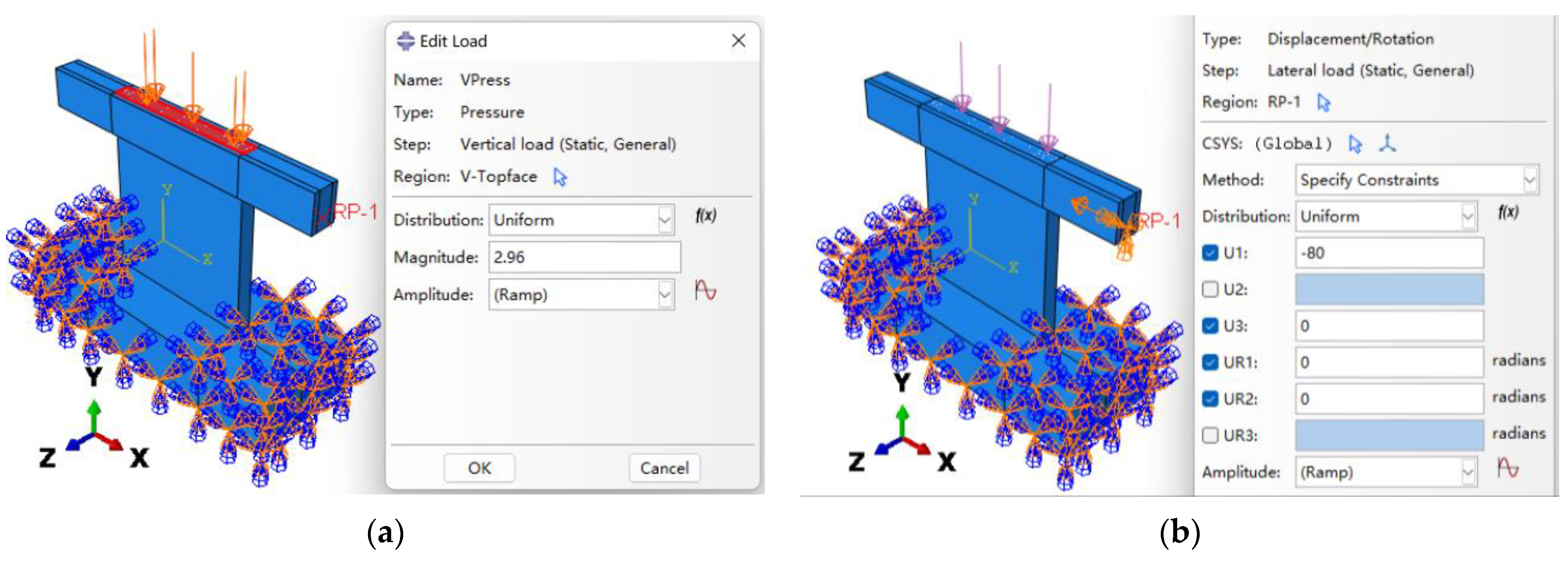
2.5. Boundary Conditions and Load Application

The schematic illustration of the test setup geometry is shown in Figure 5, and the corresponding boundary condition and loading position and direction is shown in Figure 6. For the application of horizontal loading, in order to simulate the actual boundary conditions and avoid stress concentration, a point (the height of the point from the base top surface is 2030 mm) located on the side surface of the top beam is coupled with the four vertical planes of the top beam (Figure 7a). The steel reinforcement (T3D2 truss elements) is embedded within the concrete elements and fully bonded to them, as shown in Figure 7b. The analyses are carried out in three steps: (1) the bottom beam is fixed at the base (Figure 8), (2) a constant vertical load is applied (Figure 8a), (3) the horizontal load is applied (Figure 8b). The loading history of reference experimental study is shown in Table 7. It is worth noticing that, while in the reference tests each level was cycled three times, in the numerical analyses the load was applied monotonically to reduce the computational time. This implies that the accumulated damage in each cyclic sequence was neglected. However, because the comparisons carried out in the following section are based on monotonic quantities, the ensuing considerations can be maintained.

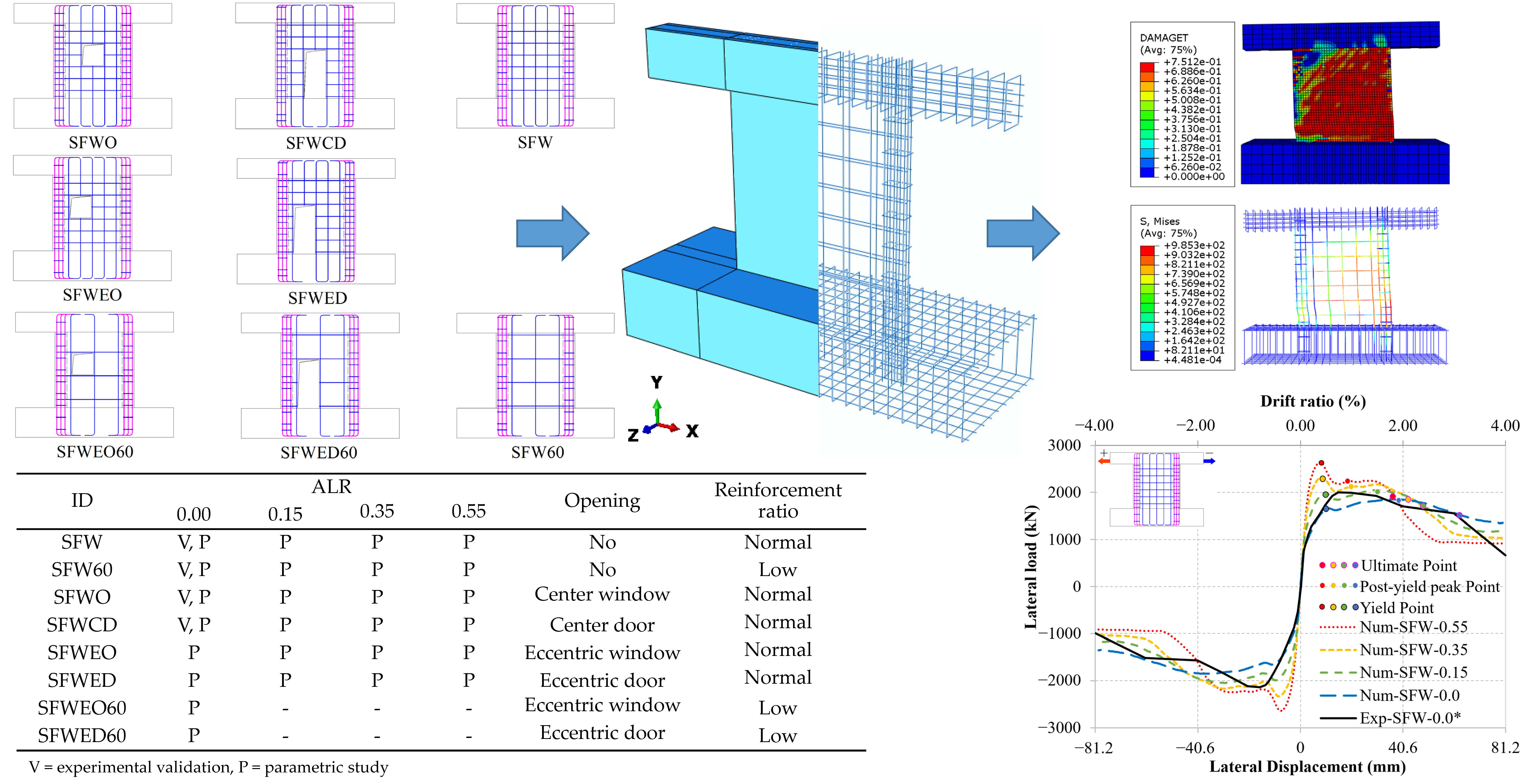
3. Validation of the Finite Element Models and Numerical Analysis

In this section, numerical analyses are presented to explore the effects on the lateral response of SFRC shear walls of different ALRs, of different openings configurations, and of different reinforcement ratios. In these analyses, the FE models presented in the previous section were used, after being calibrated against the experimental tests by Huang [16]. Having obtained accurate predictions for all four tests considered, the FE models were then used to model the response of SFRC walls under different combinations, not considered in previous experimental tests, of ALR, openings, and reinforcement ratio (Table 8).

3.1. Specimens for the Parametric Study

The specimens considered in the parametric study are shown in Figure 9 and ALRs of SFRC shear walls are list in Table 9.

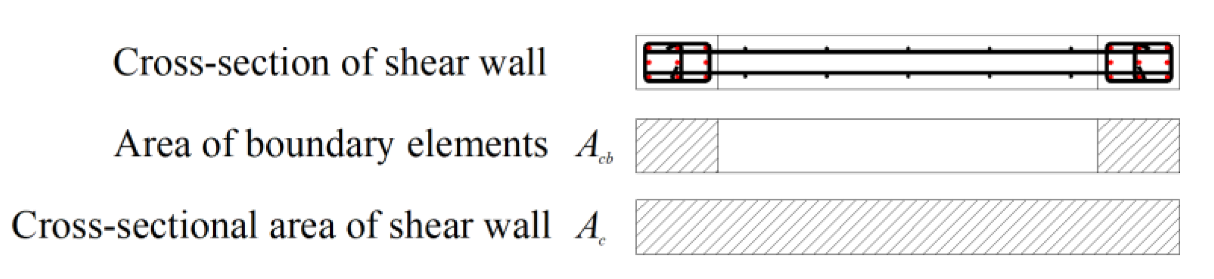
Axial Load Ratio (ALR)

The ALR is one of the main parameters considered in the parametric analyses. Two definitions (Figure 10) can be adopted for ALR: (1) considering the whole cross-section, Equations (20) and (2) considering only the boundary elements, Equation (21). In this study, the latter is adopted and four values, 0.0, 0.15, 0.35, and 0.55, are considered.
ALR = N f c , c y l A c
ALR = N f c , c y l A c b

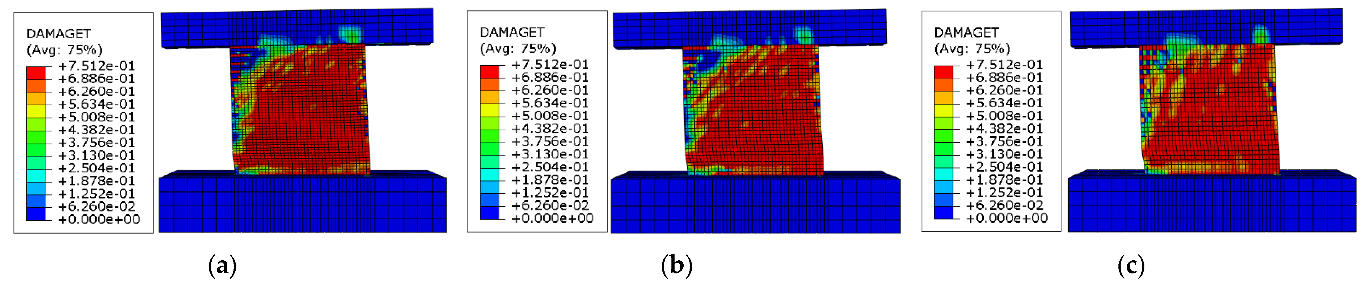
3.2. Classification of Failure Modes

Starting from the classification of failure modes in RC shear walls by Paulay et al. [51] and by Zhang et al. [52], some further elaborations are presented hereafter. Failure modes occurring in RC walls depend on size, reinforcement arrangement, and material properties [51]. Lateral loading in SFRC shear walls generates bending moment and shear, which cause flexural failure and shear failure. Thus, the actual failure mode results from a combination of these two modes. A matrix is hereafter proposed to classify the shear wall failure modes, as shown in Table 10, where it can be noticed that:
(1)
Flexural failure modes can be divided into four damage levels:
  • Undamaged (F0);
  • With sub-horizontal flexural cracks (F1);
  • With sub-horizontal flexural cracks and corner concrete crushing (F2);
  • With sub-horizontal flexural cracks and base concrete crushing (F3).
(2)
Shear failure modes can be divided into four damage levels:
  • Undamaged (S0);
  • With diffused diagonal shear cracks (S1);
  • With wide diagonal shear cracks (S2);
  • With significant diagonal compression crushing (S3).

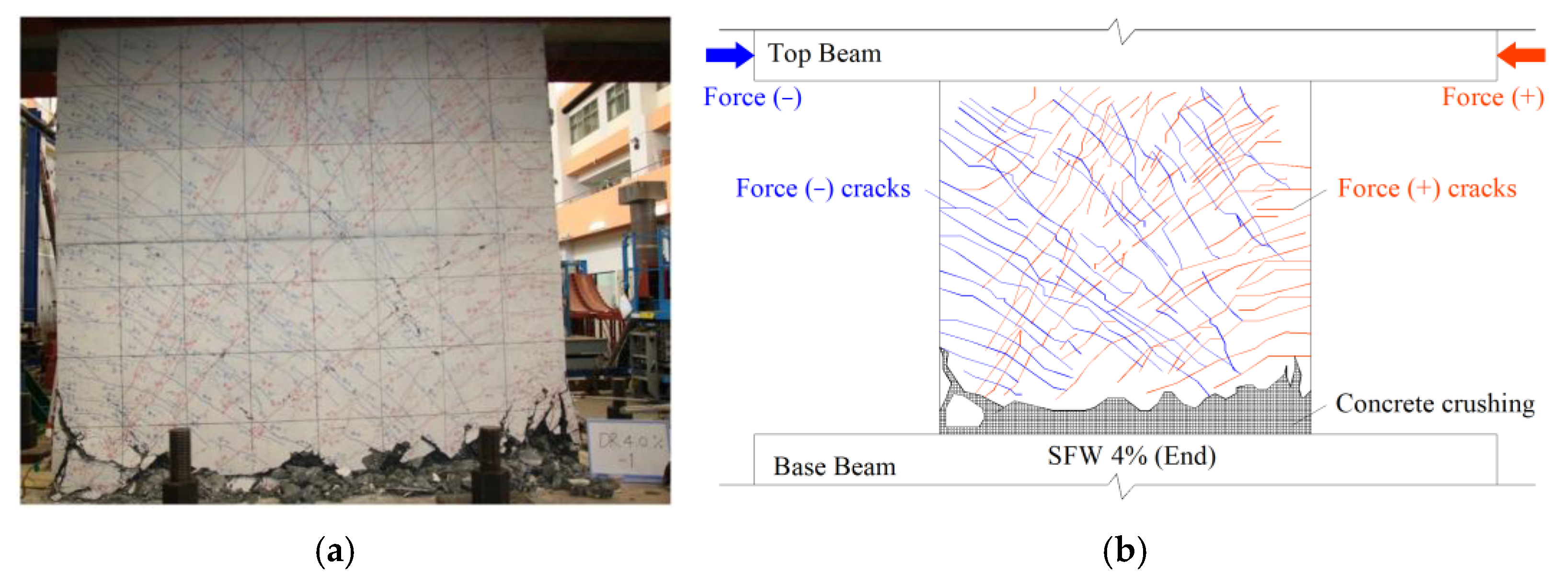
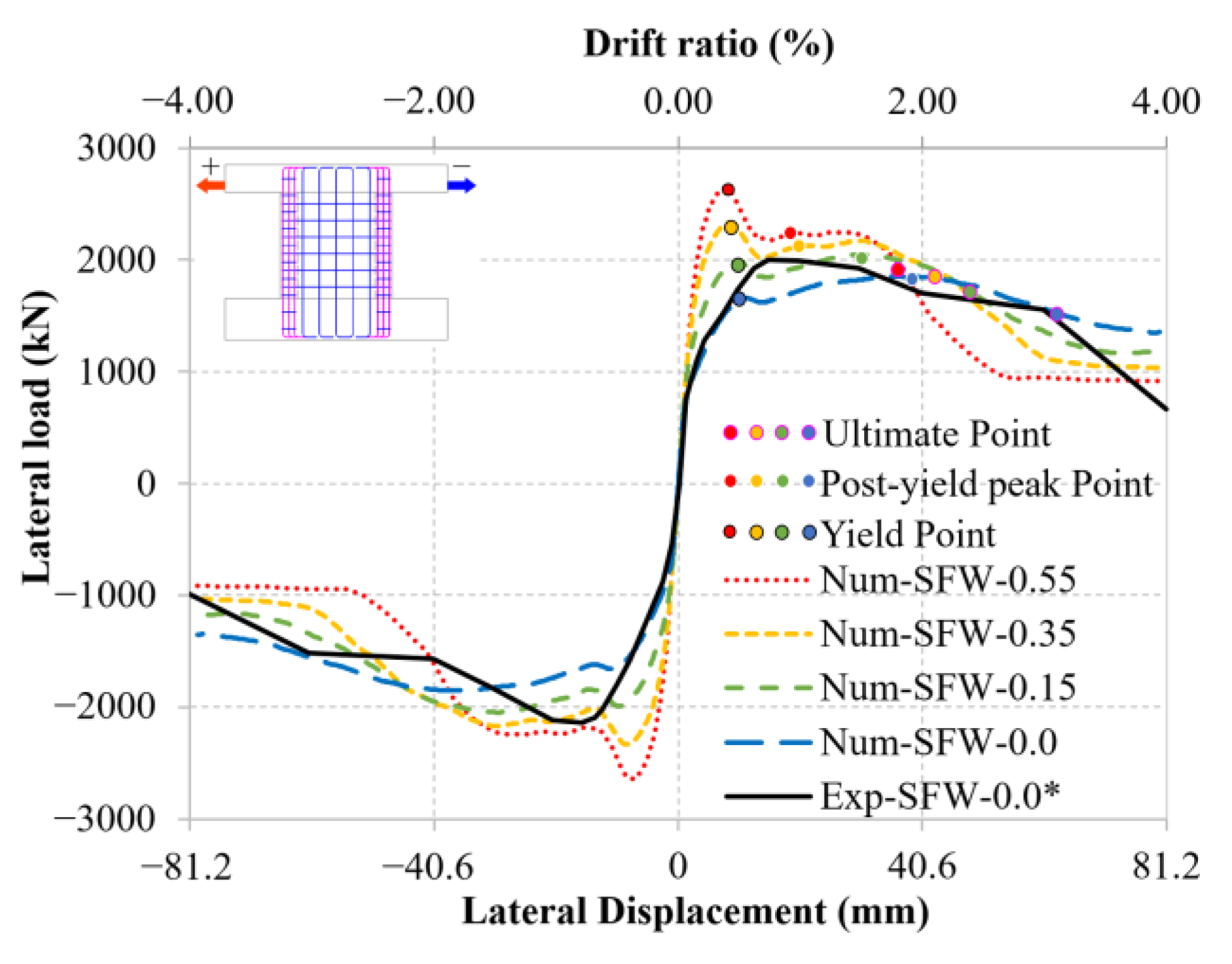
3.2.1. Specimen SFW (No Opening, Normal Reinforcement Ratio)

Figure 11 shows the failure mode of the reference specimen SFW, which is a combination of F3 and S1. The test terminates at drift ratio of 4%, with a displacement of 81.2 mm.
Figure 12 shows the comparison of the skeleton curves between test and numerical results. With ALR = 0.0, a good agreement is achieved. As ALR increases, the lateral load capacity and stiffness increase and show a positive correlation with ALR while its post-peak stage, higher ALRs result in decrease in lateral load capacity. In the end of post-peak stage, the relationship between lateral load capacity and ALRs is reversed, showing a negative correlation.
Table 11 presents the comparison of the strain distributions and crack patterns of specimen SFW between the numerical results with ALR = 0.0 and with ALR = 0.55. It is found that the flexural damage level decreases (the flexural cracks widths and the flexure-induced strains decrease), while the shear damage level increases (the shear cracks widths and the flexure-induced strains increase), indicating that higher ALR values shift the prevailing failure mechanism from flexural to shear.

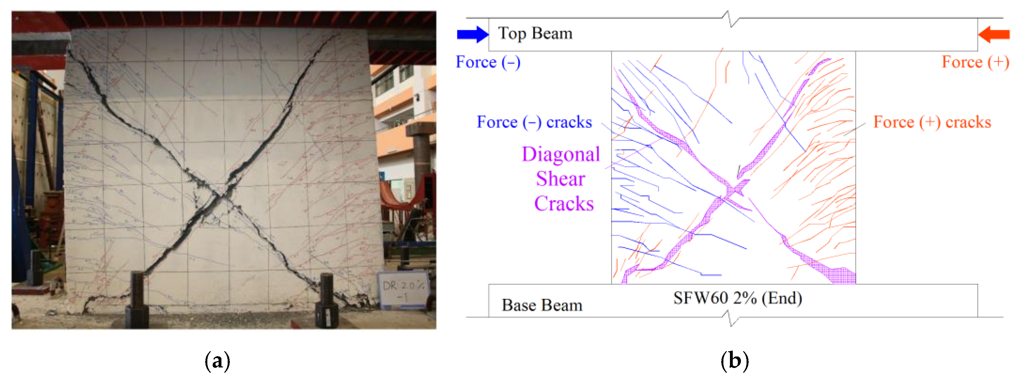
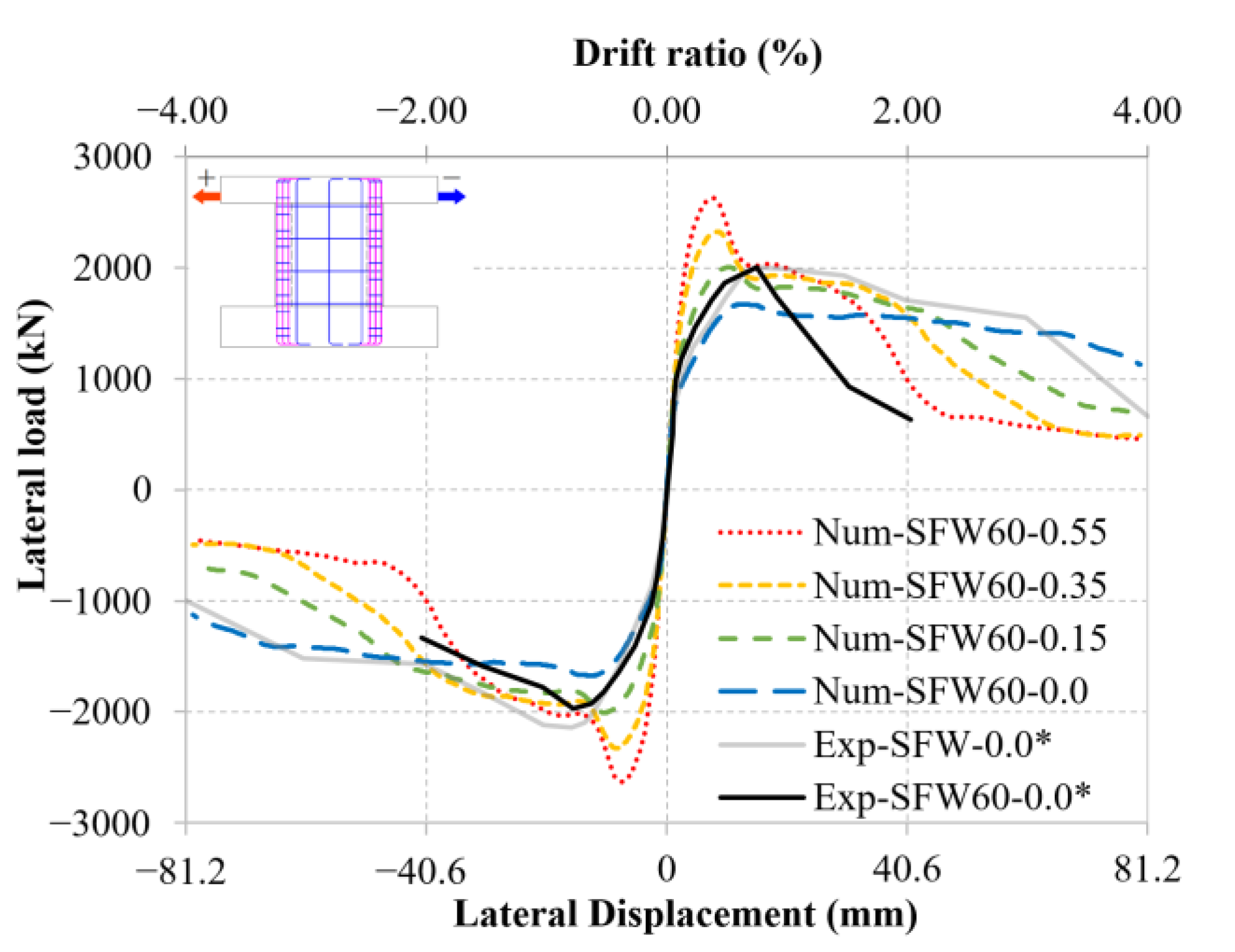
3.2.2. Specimen SFW60 (No Opening, Low Reinforcement Ratio)

Figure 13 shows the failure mode of the reference specimen SFW60, which is a combination of F1 and S2 (also known as diagonal compression failure). The test ends at drift ratio of 2%, with a displacement of 40.6 mm. Compared to specimen SFW, it is found that low reinforcement ratio results in two significant diagonal cracks across the wall, which indicate an increase in shear damage level.
Figure 14 shows the comparison of the skeleton curves between test and numerical results. As ALR increases, significant increase in load capacity and stiffness is observed; however, the skeleton curve of SFW60 shows a steeper post-peak degradation than SFW. This is because higher ALRs switch the prevailing failure mechanism from flexural to shear and low reinforcement ratio reduces the resistance to shear damage.
Table 12 presents the comparison of the strain distributions and crack patterns of specimen SFW60 between the numerical results with ALR = 0.0 and ALR = 0.55. It is found that the flexural damage level decreases (the flexural cracks widths and the flexure-induced strains decrease), while the shear damage level increases (the shear cracks widths and the flexure-induced strains increase).

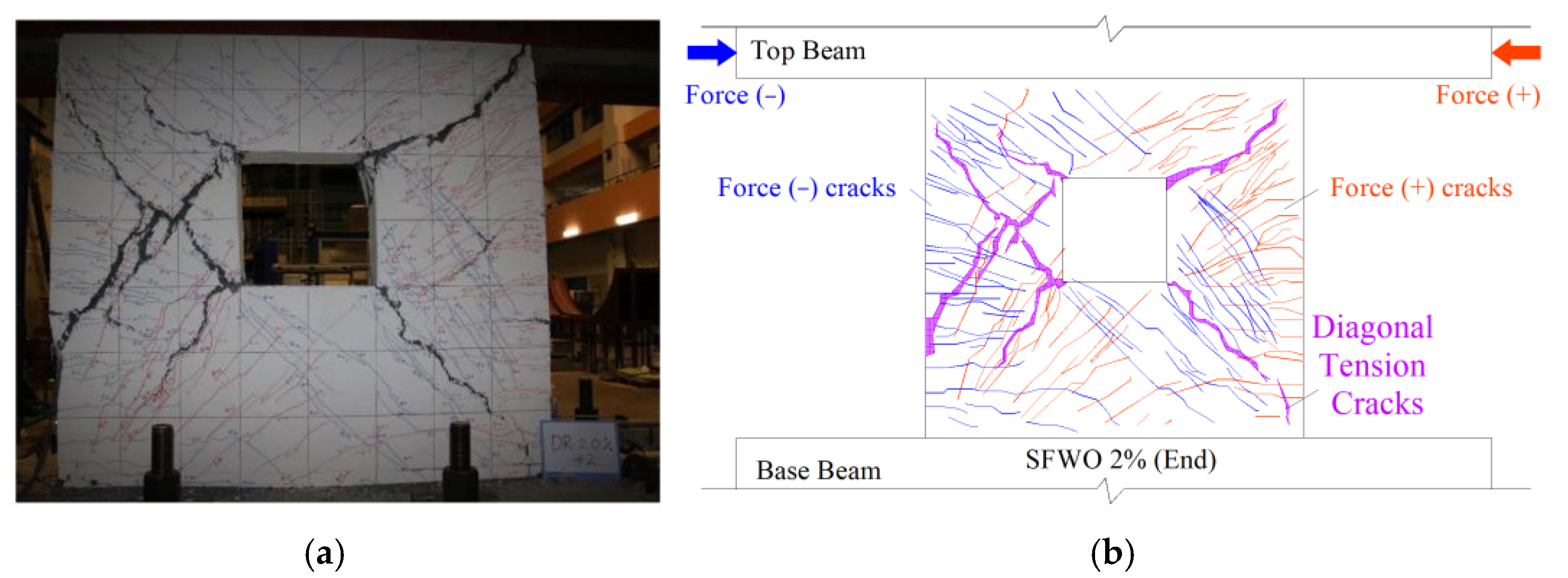
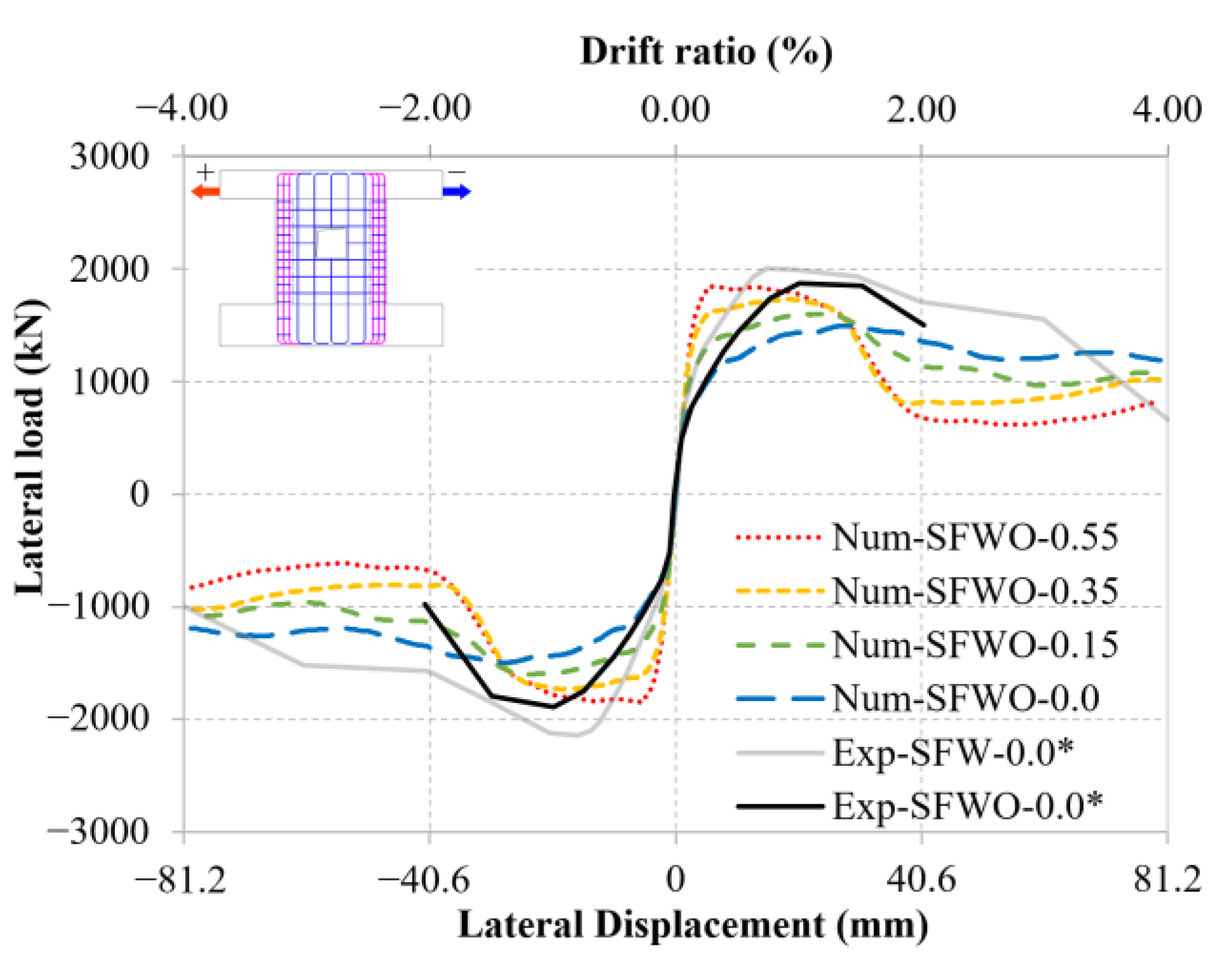
3.2.3. Specimen SFWO (Center Window Opening, Normal Reinforcement Ratio)

Figure 15 shows the failure mode of the reference specimen SFWO, which is a combination of F1 and S2. The test ends at drift ratio of 2%, with a displacement of 40.6 mm.
Figure 16 shows the comparison of the skeleton curves between test and numerical results. Compared to SFW, specimen with door opening does not show significant decrease in lateral load capacity. As ALR increases, the lateral load capacity and stiffness of the shear wall increase while the deformation capacity decreases.
Table 13 presents the comparison of the strain distributions and crack patterns of specimen SFWO between the numerical results with ALR = 0.0 and ALR = 0.55. In this latter case, the high strain and damage index concentrates within the diagonal area around the opening of the shear wall. Moreover, the highest strain occurs at the upper corner and bottom corner of the center window opening. The results show that the shear damage domains the failure pattern for the shear wall with ALR = 0.55.

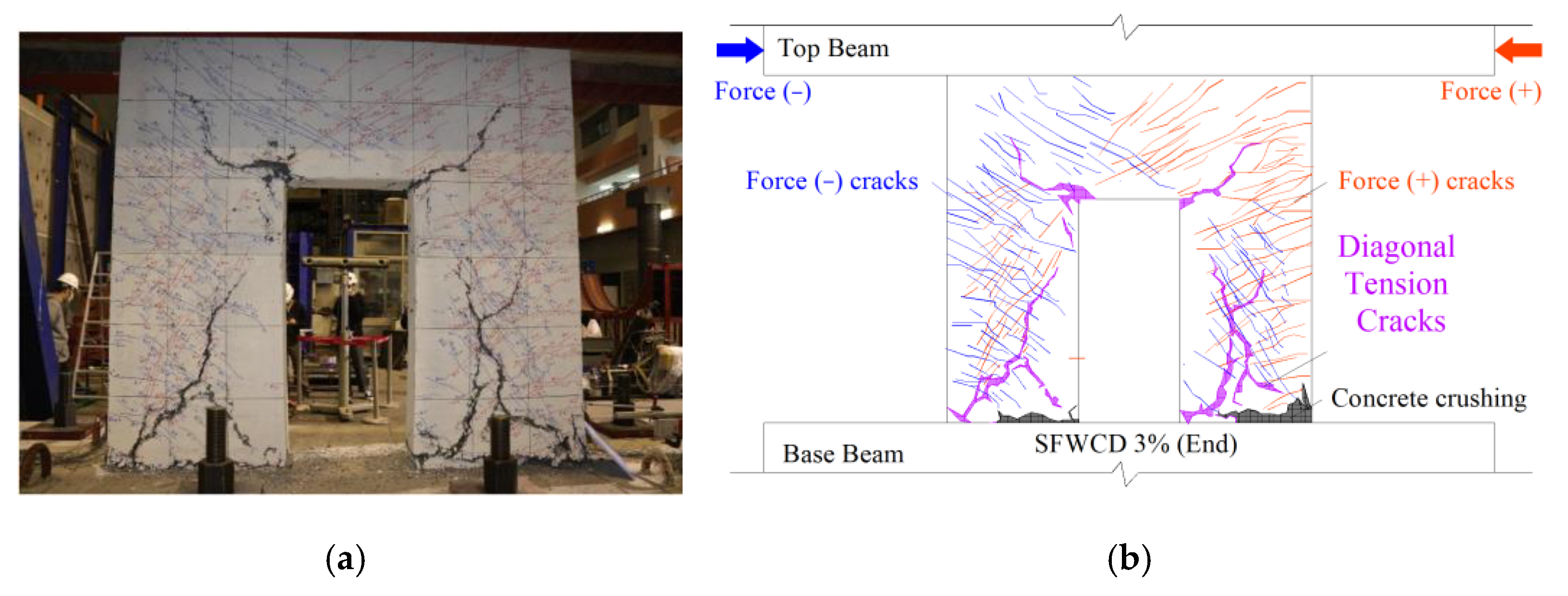
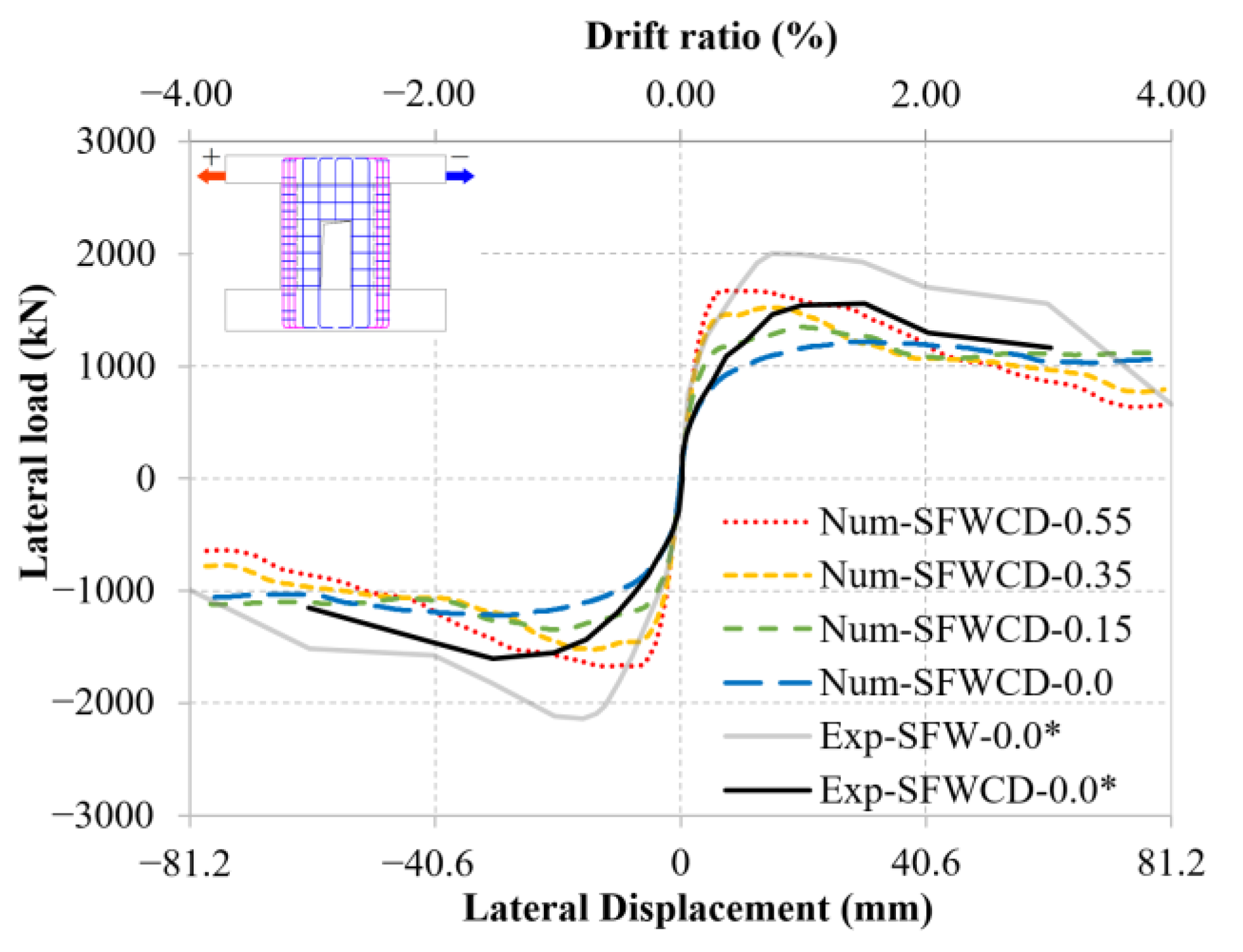
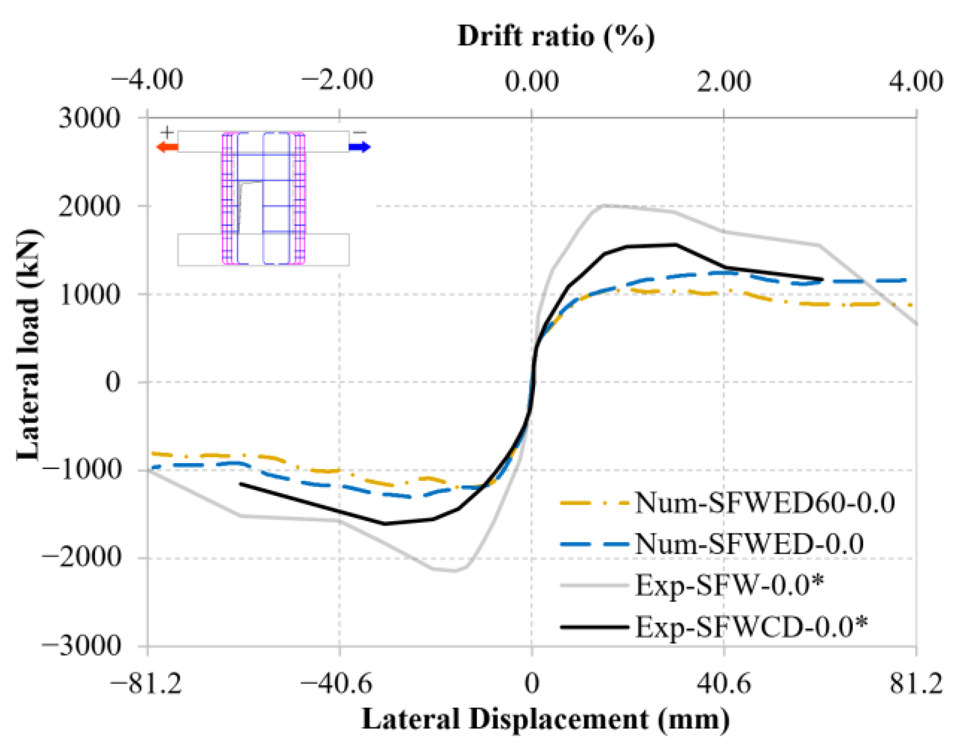
3.2.4. Specimen SFWCD (Center Door Opening, Normal Reinforcement Ratio)

Figure 17 shows the failure mode of the reference specimen SFWCD, which is a combination of F2 and S2. The test ends at drift ratio of 3%, with a displacement of 60.9 mm.
Figure 18 shows the comparison of the skeleton curves between test and numerical results. As ALR increases, the shear wall lateral load capacity and stiffness increase, but the deformation capacity does not decrease significantly. This is because two slender wall-branches on both sides of the door opening form flexural bearing system, thus contributing to the overall deformation capacity. Compared to SFWO, the ductility of this specimen with door opening does not show significant decrease with ALR increases. Therefore, window openings can be replaced by door openings with flexible materials fill the bottom space of door openings, which not only satisfies the needs of architectural functions of windows but also benefits the lateral ductility and deformation capacity of the shear wall.
Table 14 presents the comparison of the strain distributions and crack patterns of specimen SFWCD between the numerical results with ALR = 0.0 and ALR = 0.55. It is found that the flexural damage level decreases (the flexural cracks widths and the strain caused by flexural failure decrease), while the shear damage level increases (the shear cracks widths and the strain caused by flexural failure increase).

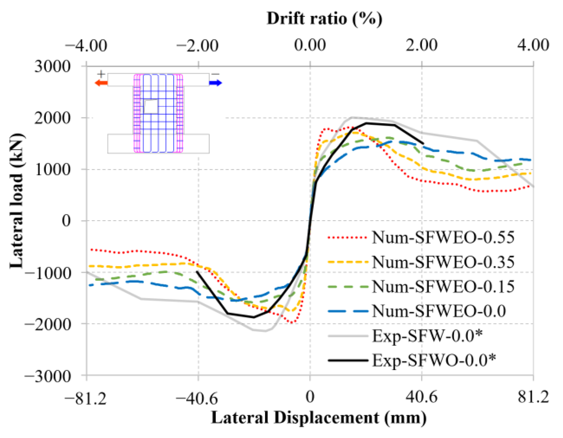
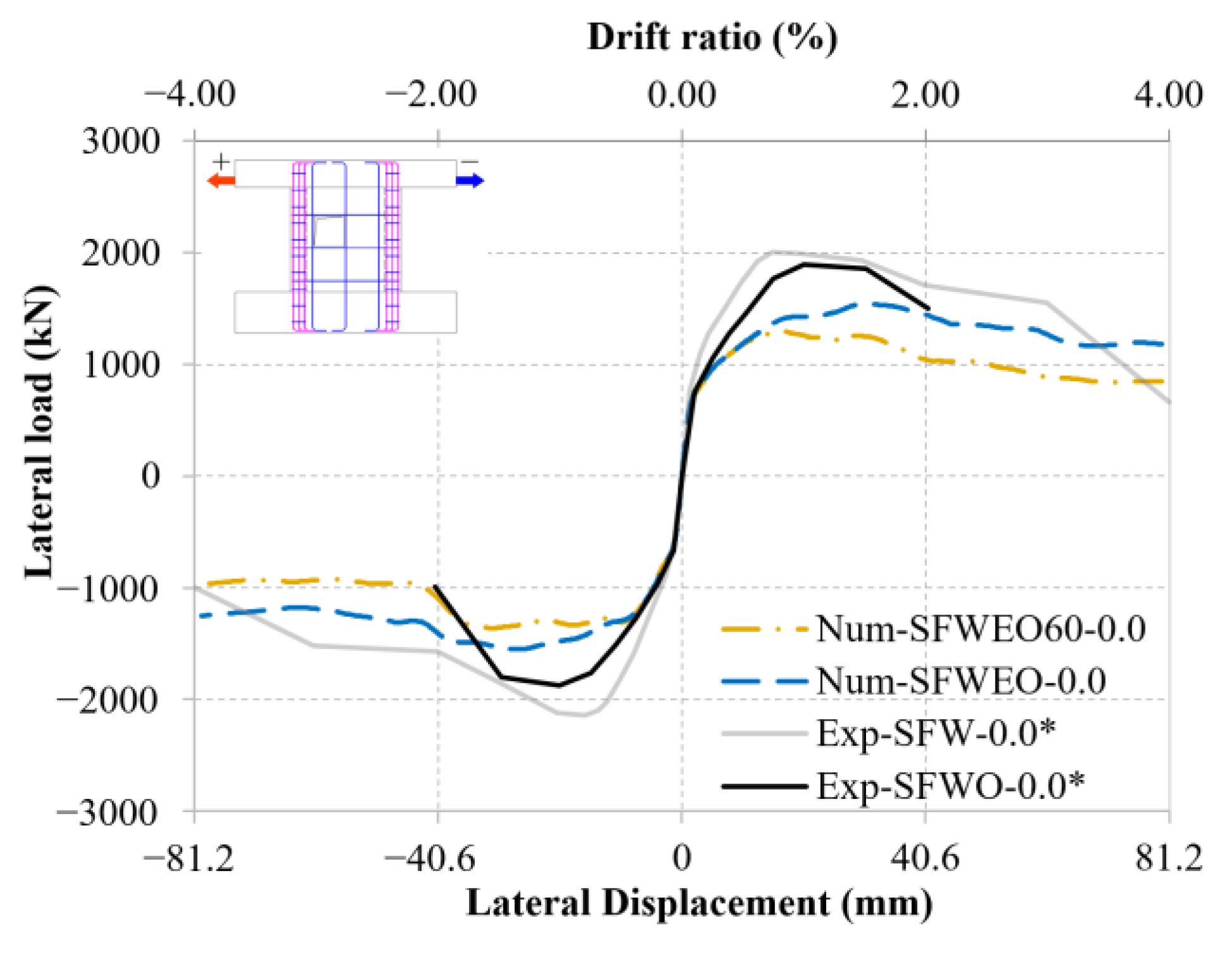
3.2.5. Specimen SFWEO (Eccentric Window Opening, Normal Reinforcement Ratio) and SFWEO60 (Eccentric Window Opening, Low Reinforcement Ratio)

Table 15 shows the failure mode of the numerical specimen SFWEO, which is a combination of F1 and S2. The numerical test ends at a drift ratio of 2%, with a displacement of 40.6 mm. Table 15 presents the comparison of the strain distributions and crack patterns of specimen SFWEO between the numerical results with ALR = 0.0 and ALR = 0.55. In this latter case, it is found that the flexural damage level is decreased (the flexural cracks widths and the strain caused by flexural failure decrease), while the shear damage level increases (the shear cracks widths and the strain caused by flexural failure increase).
Figure 19 shows the comparison of the skeleton curves between numerical results of SFWEO and experimental results of SFW and SFWO. It is found that in case of eccentric window opening, the load capacity does not significantly depend on the loading direction, which could be explained by the improvement of concrete tensile strength by steel fiber. To further discover the reasons, this paper study the effect of reinforcement ratio. Figure 20 shows the comparison of the skeleton curves between numerical results of SFWEO and SFWEO60. It is found that as reinforcement ratio decreases, the differences in the lateral load capacity under push and pull loading directions increases.

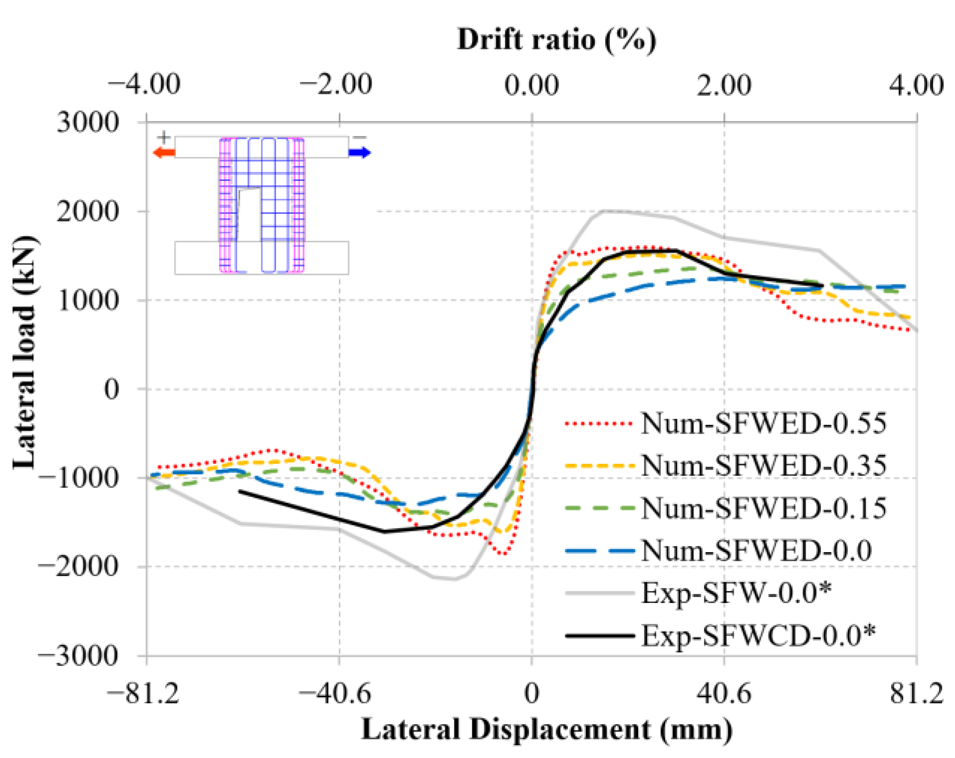
3.2.6. Specimen SFWED (Eccentric Door Opening, Normal Reinforcement Ratio) and SFWED60 (Eccentric Door Opening, Low Reinforcement Ratio)

Table 16 shows the failure mode of the numerical specimen SFWED, which is a combination of F2 and S2. The numerical test ends at a drift ratio of 3%, with a displacement of 60.9 mm. Table 16 presents the comparison of the strain distributions and crack patterns of specimen SFWED between the numerical results with ALR = 0.0 and ALR = 0.55. It is found that the flexural damage level decreases (the flexural cracks widths and the strain caused by flexural failure decrease), while the shear damage level increases (the shear cracks widths and the strain caused by flexural failure increase). The largest compressive damage moves from the shear wall bottom to mid-height.
Figure 21 shows the comparison of the skeleton curves between numerical results of SFWED and experimental results of SFW and SFWCD. As ALR increases, the lateral load capacity and stiffness of the shear wall increase, while the deformation capacity does not decrease significantly. This is because two slender walls-branches form on both sides of the door opening, thus contributing to the overall deformation capacity. Figure 22 shows the comparison of the skeleton curves between numerical results of SFWED and SFWED60. It is found that as reinforcement ratio decreases, the differences in the lateral load capacity under push and pull loading directions increases, compared to window openings, these differences of door openings are more significant.

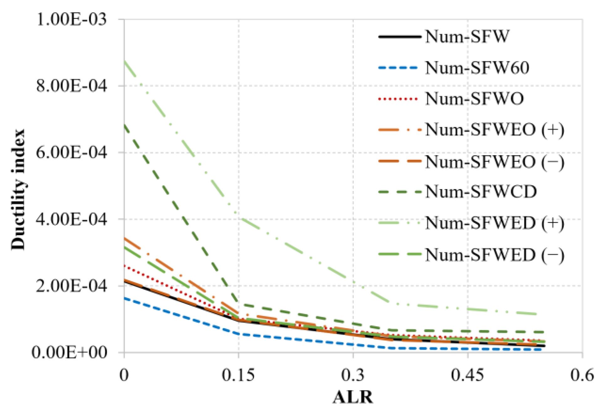
3.3. Estimate of Ductility

Ductility expresses the deformation capacity of structures in the plastic range. The ductility index μ d is defined as:
μ d = D u / D y
where D u is the ultimate displacement, here defined at 0.85 of post-yield peak load, D y is the displacement at yield load, defined as the point where tension reinforcement yields, while the post-yield peak load is defined as the maximum load in the post-yield branch (Figure 23).
Table 17 presents the comparison of the ductility indices calculated from the numerical results.
Figure 24 presents the comparison of the ductility capacity of specimens among the numerical results with ALR = 0.0, 0.15, 0.35, and 0.55. It is found that as ALR increases, the ductility capacity of the walls decreases. The decrease in the entire transverse reinforcement in specimen SFW60, both in the end portions and in the center wall, gives a decrease in ductility compared with SFW. In cases of eccentric openings, the ductility capacity is affected by the loading direction. The ductility capacity in the presence of center opening lies between the two ductility capacities (+ and −) of the cases with eccentric openings.

4. Conclusions

A numerical investigation of the lateral capacity of shear walls made of steel-fiber-reinforced concrete (SFRC) was carried out, with the purpose of studying the effects, both of door and window openings, and of the axial load ratio (ALR). For the numerical investigation, finite element models were implemented based on the SFRC walls tested by Huang [16], which served as benchmark to calibrate their accuracy. After assessing the numerical model accuracy, a set of parametric analyses was carried out to study the effects of the ALR, of different opening configurations, and of the reinforcement ratio. Load–displacement curves, failure modes, crack patterns, and strain distributions were used as terms of comparison. The main conclusions of this study can be summarized as follows:
  • A classification of the shear wall failure modes is proposed, where it is observed that, as ALR increases, the flexural-induced damage decreases, while the shear-induced damage increases, thus reducing both ductility and deformation capacity, as shown in the last section.
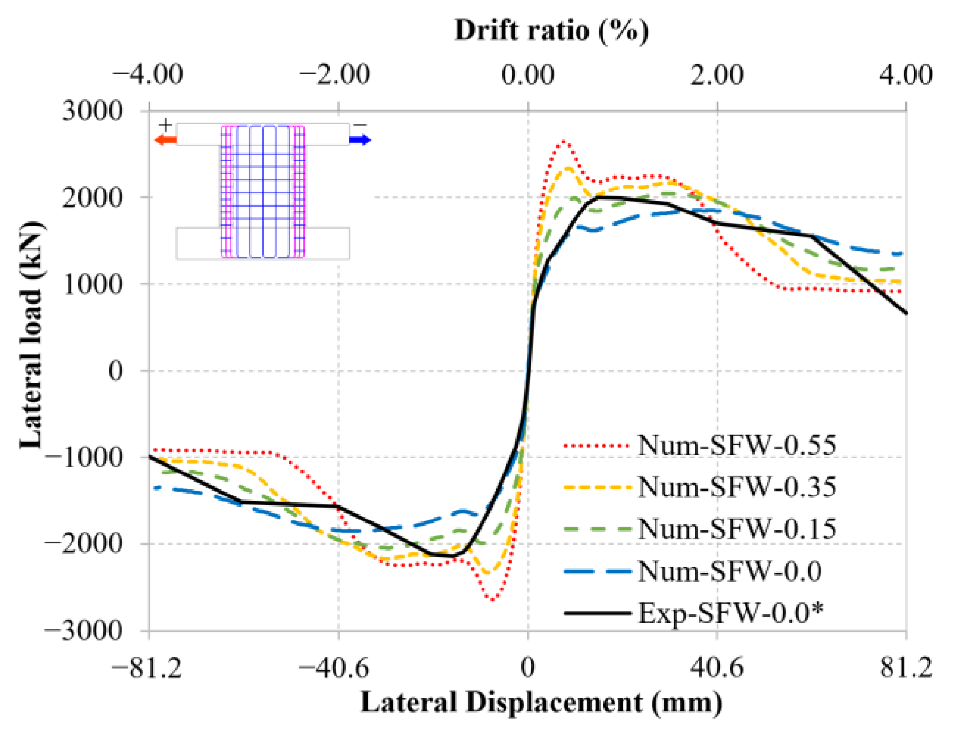
  • As ALR increases, both lateral load capacity and stiffness increase and show a positive correlation with ALR while in the final post-peak stage, the relationship between lateral load capacity and ALRs is reversed, showing a negative correlation.
  • Even in the presence of window or door openings, and with ALR up to 0.55, the specimens still show relatively good lateral load and deformation capacity, thanks to the improvement introduced by the SFRC.
  • In general, window openings tend to reduce the lateral deformation capacity, while door openings tend to reduce the lateral load capacity. Therefore, if the lateral deformation capacity is of concern, window openings can be preferably obtained from door openings with a flexible infill at the bottom.
  • In the case of eccentric openings, as the reinforcement ratio decreases, the difference in the lateral load capacity in opposite directions increases. This phenomenon is more significant with door than with window openings.
Having ascertained the role of the parameters considered in this paper, further studies are currently under way to explore the role of other parameters, for example, the ratio between the openings size and the shear wall size.

Author Contributions

Conceptualization, Z.L., H.Z. and G.M.; methodology, Z.L., H.Z. and G.M.; software, Z.L., H.Z., G.M. and C.C.; validation, Z.L., H.Z. and G.M.; formal analysis, Z.L., H.Z. and G.M.; investigation, Z.L., H.Z. and G.M.; resources, Z.L., H.Z. and G.M.; data curation, Z.L; writing—original draft preparation, Z.L.; writing—review and editing, Z.L., H.Z., G.M. and C.C.; visualization, Z.L. and G.M.; supervision, H.Z. and G.M.; project administration, H.Z.; funding acquisition, H.Z. All authors have read and agreed to the published version of the manuscript.

Funding

This research received the financially supported by the National Key R&D Program of China (Grant Nos. 2019YFE0112600), the National Natural Science Foundation of China (Grant Nos. 52078459), and the Natural Science Foundation of Zhejiang Province (Grant Nos. LZ22E080005).

Institutional Review Board Statement

Not applicable.

Informed Consent Statement

Not applicable.

Data Availability Statement

Not applicable.

Acknowledgments

The authors of this paper is very grateful to Wen-Cheng Liao of National Taiwan University for providing the experimental data of the concerned shear walls, and in the process of writing papers to provide valuable advice and suggestions.

Conflicts of Interest

The authors declare no conflict of interest.

References

  1. Zhang, H.; Zhang, Y.; Lu, X.; Duan, Y.; Zhang, H. Influence of Axial Load Ratio on the Seismic Behavior of Steel Fiber–Reinforced Concrete Composite Shear Walls. J. Struct. Eng. 2020, 146, 04019171. [Google Scholar] [CrossRef]
  2. Alarcon, C.; Hube, M.; de la Llera, J. Effect of axial loads in the seismic behavior of reinforced concrete walls with unconfined wall boundaries. Eng. Struct. 2014, 73, 13–23. [Google Scholar] [CrossRef]
  3. Su, R.; Wong, S. Seismic behaviour of slender reinforced concrete shear walls under high axial load ratio. Eng. Struct. 2007, 29, 1957–1965. [Google Scholar] [CrossRef]
  4. Li, X.; Zhang, J.; Cao, W. Hysteretic behavior of high-strength concrete shear walls with high-strength steel bars: Experimental study and modelling. Eng. Struct. 2020, 214, 110600. [Google Scholar] [CrossRef]
  5. Lu, X.; Zhang, Y.; Zhang, H.; Zhang, H.; Xiao, R. Experimental study on seismic performance of steel fiber reinforced high strength concrete composite shear walls with different steel fiber volume fractions. Eng. Struct. 2018, 171, 247–259. [Google Scholar] [CrossRef]
  6. Hosseini, S.A.; Kheyroddin, A.; Mastali, M. An experimental investigation into the impacts of eccentric openings on the in-plane behavior of squat RC shear walls. Eng. Struct. 2019, 197, 109410. [Google Scholar] [CrossRef]
  7. Fattuhi, N.I. Strength of Sfrc Corbels Subjected to Vertical Load. J. Struct. Eng. Asce 1990, 116, 701–718. [Google Scholar] [CrossRef]
  8. Thomas, J.; Ramaswamy, A. Mechanical Properties of Steel Fiber-Reinforced Concrete. J. Mater. Civ. Eng. 2007, 19, 385–392. [Google Scholar] [CrossRef]
  9. Jayanth, K.; Prakash, M.N.S.; Suresh, G.S.; Naveen, B.O. Studies on the behaviour of steel fibre-reinforced concrete under monotonic and repeated cyclic stress in compression. Arch. Civ. Mech. Eng. 2022, 22, 50. [Google Scholar] [CrossRef]
  10. Shi, X.; Park, P.; Rew, Y.; Huang, K.; Sim, C. Constitutive behaviors of steel fiber reinforced concrete under uniaxial compression and tension. Constr. Build. Mater. 2020, 233, 117316. [Google Scholar] [CrossRef]
  11. Zhang, H.; Liu, X.; Yi, W. Experimental Investigation on Stress Redistribution and Load-Transfer Paths of Shear Walls with Openings. J. Struct. Eng. 2018, 144, 04018149. [Google Scholar] [CrossRef]
  12. Popescu, C.; Sas, G.; Sabău, C.; Blanksvärd, T. Effect of Cut-Out Openings on the Axial Strength of Concrete Walls. J. Struct. Eng. 2016, 142, 04016100. [Google Scholar] [CrossRef]
  13. Massone, L.M.; Muñoz, G.; Rojas, F. Experimental and numerical cyclic response of RC walls with openings. Eng. Struct. 2019, 178, 318–330. [Google Scholar] [CrossRef]
  14. Wang, J.; Sakashita, M.; Kono, S.; Tanaka, H. Shear behaviour of reinforced concrete structural walls with eccentric openings under cyclic loading: Experimental study. Struct. Des. Tall Spec. Build. 2012, 21, 669–681. [Google Scholar] [CrossRef]
  15. Dashti, F.; Dhakal, R.P.; Pampanin, S. Validation of a Numerical Model for Prediction of Out-of-Plane Instability in Ductile Structural Walls under Concentric In-Plane Cyclic Loading. J. Struct. Eng. 2018, 144, 04018039. [Google Scholar] [CrossRef]
  16. Huang, C.-Y. The Study on Strength Prediction Model and Behavior of High Strength Steel Fiber Reinforced Concrete Walls with Opening. Master’s Thesis, Department of Civil Engineering College of Engineering, National Taiwan University, Taipei, Taiwan, 2022. Available online: https://drive.google.com/file/d/1wpbOPdxmzh0RWemd0QkI21TI6X7JLayG/view?usp=sharing (accessed on 10 August 2022).
  17. Ma, J.; Ning, C.-L.; Li, B. Peak Shear Strength of Flanged Reinforced Concrete Squat Walls. J. Struct. Eng. 2020, 146, 04020037. [Google Scholar] [CrossRef]
  18. Wei, F.; Chen, H.; Xie, Y. Experimental study on seismic behavior of reinforced concrete shear walls with low shear span ratio. J. Build. Eng. 2022, 45, 103602. [Google Scholar] [CrossRef]
  19. Fatemi, H.; Paultre, P.; Lamarche, C.-P. Evaluation of Inelastic Higher-Mode Effects on the Seismic Behavior of RC Structural Walls. J. Struct. Eng. 2020, 146, 04020016. [Google Scholar] [CrossRef] [Green Version]
  20. Alwashali, H.; Maeda, M.; Ogata, Y.; Aizawa, N.; Tsurugai, K. Residual seismic performance of damaged reinforced concrete walls. Eng. Struct. 2021, 243, 112673. [Google Scholar] [CrossRef]
  21. Rong, X.-L.; Zheng, S.-S.; Zhang, Y.-X.; Zhang, X.-Y.; Dong, L.-G. Experimental study on the seismic behavior of RC shear walls after freeze-thaw damage. Eng. Struct. 2020, 206, 110101. [Google Scholar] [CrossRef]
  22. Erbaş, Y.; Anıl, Ö.; Özdemir, A.; Kopraman, Y. Prediction of capacity of reinforced concrete shear wall with multiple openings by using nonlinear finite element analysis. Struct. Concr. 2022; Early view. [Google Scholar] [CrossRef]
  23. Kim, S.-H.; Lee, E.-K.; Kang, S.-M.; Park, H.-G.; Park, J.-H. Effect of boundary confinement on ductility of RC walls. Eng. Struct. 2021, 230, 111695. [Google Scholar] [CrossRef]
  24. Zhang, Y.; Yuan, G.; Shu, Q.; Zhu, M.; Lu, L. Investigation on seismic behavior of RC shear walls with multiple post-construction openings based on experiment and simulation. J. Build. Eng. 2022, 46, 103707. [Google Scholar] [CrossRef]
  25. Yang, C.; Chou, Y.-C.; Hung, C.-C. Seismic behavior of full-scale wall piers with high-strength steel reinforcement. Eng. Struct. 2022, 256, 114068. [Google Scholar] [CrossRef]
  26. Barbachyn, S.M.; Devine, R.D.; Thrall, A.P.; Kurama, Y.C. Behavior of Nuclear RC Shear Walls Designed for Similar Lateral Strengths Using Normal-Strength versus High-Strength Materials. J. Struct. Eng. 2020, 146, 04020252. [Google Scholar] [CrossRef]
  27. Hung, C.-C.; Hsieh, P.-L. Comparative study on shear failure behavior of squat high-strength steel reinforced concrete shear walls with various high-strength concrete materials. Structures 2020, 23, 56–68. [Google Scholar] [CrossRef]
  28. Zhang, J.; Liu, J.; Li, X.; Cao, W. Seismic behavior of steel fiber-reinforced high-strength concrete mid-rise shear walls with high-strength steel rebar. J. Build. Eng. 2021, 42, 102462. [Google Scholar] [CrossRef]
  29. Zhao, J.; Dun, H. A restoring force model for steel fiber reinforced concrete shear walls. Eng. Struct. 2014, 75, 469–476. [Google Scholar] [CrossRef]
  30. Li, X.; Zhang, J.; Cao, W.; Zhu, Y. Seismic behavior of steel fiber reinforced high strength concrete shear walls with different embedded steel configurations. J. Build. Eng. 2022, 53, 104551. [Google Scholar] [CrossRef]
  31. Sakr, M.A.; El-Khoriby, S.R.; Khalifa, T.M.; Nagib, M.T. Modeling of RC shear walls strengthened with ultra-high performance fiber reinforced concrete (UHPFRC) jackets. Eng. Struct. 2019, 200, 109696. [Google Scholar] [CrossRef]
  32. Nagib, M.T.; Sakr, M.A.; El-Khoriby, S.R.; Khalifa, T.M. Cyclic behaviour of squat reinforced concrete shear walls strengthened with ultra-high performance fiber reinforced concrete. Eng. Struct. 2021, 246, 112999. [Google Scholar] [CrossRef]
  33. Hung, C.-C.; Li, H.; Chen, H.-C. High-strength steel reinforced squat UHPFRC shear walls: Cyclic behavior and design implications. Eng. Struct. 2017, 141, 59–74. [Google Scholar] [CrossRef]
  34. Kassem, W.; Elsheikh, A. Estimation of Shear Strength of Structural Shear Walls. J. Struct. Eng. 2010, 136, 1215–1224. [Google Scholar] [CrossRef]
  35. Zhang, H.; Fang, Y.; Duan, Y.; Du, G. The V-MVLE model for cyclic failure behavior simulation of planar RC members. Thin-Walled Struct. 2022, 181, 110159. [Google Scholar] [CrossRef]
  36. Abdullah, S.A.; Wallace, J.W. Drift Capacity at Axial Failure of RC Structural Walls and Wall Piers. J. Struct. Eng. 2021, 147, 04021062. [Google Scholar] [CrossRef]
  37. Li, B.; Chi, Y.; Xu, L.; Li, C.; Shi, Y. Cyclic tensile behavior of SFRC: Experimental research and analytical model. Constr. Build. Mater. 2018, 190, 1236–1250. [Google Scholar] [CrossRef]
  38. Lee, S.C.; Oh, J.H.; Cho, J.Y. Compressive Behavior of Fiber-Reinforced Concrete with End-Hooked Steel Fibers. Materials 2015, 8, 1442–1458. [Google Scholar] [CrossRef] [Green Version]
  39. Wang, X.; Fan, F.; Lai, J.; Xie, Y. Steel fiber reinforced concrete: A review of its material properties and usage in tunnel lining. Structures 2021, 34, 1080–1098. [Google Scholar] [CrossRef]
  40. Kytinou, V.K.; Chalioris, C.E.; Karayannis, C.G.; Elenas, A. Effect of Steel Fibers on the Hysteretic Performance of Concrete Beams with Steel Reinforcement-Tests and Analysis. Materials 2020, 13, 2923. [Google Scholar] [CrossRef]
  41. Ravichandran, D.; Prem, P.R.; Kaliyavaradhan, S.K.; Ambily, P. Influence of fibers on fresh and hardened properties of Ultra High Performance Concrete (UHPC)—A review. J. Build. Eng. 2022, 57, 104922. [Google Scholar] [CrossRef]
  42. Li, B.; Prem, P.R.; Kaliyavaradhan, S.K.; Ambily, P. Experimental investigation on the stress-strain behavior of steel fiber reinforced concrete subjected to uniaxial cyclic compression. Constr. Build. Mater. 2017, 140, 109–118. [Google Scholar] [CrossRef]
  43. Deng, F.; Chi, Y.; Xu, L.; Huang, L.; Hu, X. Constitutive behavior of hybrid fiber reinforced concrete subject to uniaxial cyclic tension: Experimental study and analytical modeling. Constr. Build. Mater. 2021, 295, 123650. [Google Scholar] [CrossRef]
  44. dos Santos, L.R.; de Sousa Cardoso, H.; Caldas, R.B.; Grilo, L.F. Finite element model for bolted shear connectors in concrete-filled steel tubular columns. Eng. Struct. 2020, 203, 109863. [Google Scholar] [CrossRef]
  45. Li, W.; Han, L.-H. Seismic performance of CFST column to steel beam joints with RC slab: Analysis. J. Constr. Steel Res. 2011, 67, 127–139. [Google Scholar] [CrossRef]
  46. Fang, C.; Ali, M.S.M.; Sheikh, A.H.; Singh, M. Numerical and Finite-Element Analysis of Short Ultrahigh-Performance Fiber-Reinforced Concrete Columns. J. Struct. Eng. 2019, 145, 04019111. [Google Scholar] [CrossRef]
  47. Cai, J.; Pan, J.; Tan, J.; Vandevyvere, B. Nonlinear finite-element analysis for hysteretic behavior of ECC-encased CFST columns. Structures 2020, 25, 670–682. [Google Scholar] [CrossRef]
  48. Bonilla, J.; Bezerra, L.M.; Mirambell, E. Resistance of stud shear connectors in composite beams using profiled steel sheeting. Eng. Struct. 2019, 187, 478–489. [Google Scholar] [CrossRef]
  49. Abouali, S.; Shahverdi, M.; Ghassemieh, M.; Motavalli, M. Nonlinear simulation of reinforced concrete beams retrofitted by near-surface mounted iron-based shape memory alloys. Eng. Struct. 2019, 187, 133–148. [Google Scholar] [CrossRef]
  50. Raza, A.; Khan, Q.u.Z.; Ahmad, A. Investigation of HFRC columns reinforced with GFRP bars and spirals under concentric and eccentric loadings. Eng. Struct. 2021, 227, 111461. [Google Scholar] [CrossRef]
  51. Paulay, T.; Priestly, M.J.N. Seismic Design of Reinforced Concrete and Masonry Buildings, 1st ed.; John Wiley & Sons, Inc.: New York, NY, USA, 1992. [Google Scholar]
  52. Zhang, H.Y.; Cheng, X.; Li, Y.; Du, X. Prediction of failure modes, strength, and deformation capacity of RC shear walls through machine learning. J. Build. Eng. 2022, 50, 104145. [Google Scholar] [CrossRef]
Figure 1. Geometry and reinforcement of the specimens tested by [16]: (a) SFW, (b) SFW60, (c) SFWO, (d) SFWCD. These specimens were used to calibrate the FE models.
Buildings 12 02032 g001
Figure 2. Comparison of crack patterns among different concrete grids. (a) Concrete grid = 40. (b) Concrete grid = 50. (c) Concrete grid = 70.
Buildings 12 02032 g002
Figure 3. Accuracy of load–displacement curves with respect to experimental test SFW-0.0 using different concrete grids.
Buildings 12 02032 g003
Figure 4. Mesh used in the model of the SFRC shear wall (concrete grid = 50).
Buildings 12 02032 g004
Figure 5. Schematic illustration of test setup details.
Buildings 12 02032 g005
Figure 6. Shear wall boundary condition and loading position and direction.
Buildings 12 02032 g006
Figure 7. Details of FE model (a) coupling of FE model; (b) embedded region of FE model.
Buildings 12 02032 g007
Figure 8. Application of loads (a) vertical load of FE model; (b) horizontal load of FE model.
Buildings 12 02032 g008
Figure 9. Geometry and reinforcement of the specimens for the parametric study: (a) SFWEO, (b) SFWED, (c) SFWEO60, (d) SFWED60, in addition to those shown in Figure 1.
Buildings 12 02032 g009aBuildings 12 02032 g009b
Figure 10. Different estimates of the shear area of a shear wall with boundary elements.
Buildings 12 02032 g010
Figure 11. Specimen SFW: failure mode. (a) Failure mode photo [16]. (b) Failure mode schematic.
Buildings 12 02032 g011
Figure 12. Specimen SFW: comparison of skeleton curves between test and numerical results. (*) denotes that the data were obtained from the experimental tests by Huang [16].
Buildings 12 02032 g012
Figure 13. Specimen SFW60: failure mode. (a) Failure mode photo [16]. (b) Failure mode schematic.
Buildings 12 02032 g013
Figure 14. Specimen SFW60: comparison of skeleton curves between test and numerical results. (*) denotes that the data were obtained from the experimental tests by Huang [16].
Buildings 12 02032 g014
Figure 15. Specimen SFWO: failure mode. (a) Failure mode photo [16]. (b) Failure mode schematic.
Buildings 12 02032 g015
Figure 16. Specimen SFWO: comparison of skeleton curves between test and numerical results. (*) denotes that the data were obtained from the experimental tests by Huang [16].
Buildings 12 02032 g016
Figure 17. Specimen SFWCD: failure mode. (a) Failure mode photo [16]. (b) Failure mode schematic.
Buildings 12 02032 g017
Figure 18. Specimen SFWCD [16]: comparison of skeleton curves between test and numerical results. (*) denotes that the data were obtained from the experimental tests by Huang [16].
Buildings 12 02032 g018
Figure 19. Specimen SFWEO: comparison of skeleton curves between numerical results of SFWO and SFWEO. (*) denotes that the data were obtained from the experimental tests by Huang [16].
Buildings 12 02032 g019
Figure 20. Specimen SFWEO60: comparison of skeleton curves between numerical results of SFWEO and SFWEO60. (*) denotes that the data were obtained from the experimental tests by Huang [16].
Buildings 12 02032 g020
Figure 21. Specimen SFWED: comparison of skeleton curves between numerical results of SFWCD and SFWED. (*) denotes that the data were obtained from the experimental tests by Huang [16].
Buildings 12 02032 g021
Figure 22. Specimen SFWED60: comparison of skeleton curves between numerical results of SFWED and SFWED60. (*) denotes that the data were obtained from the experimental tests by Huang [16].
Buildings 12 02032 g022
Figure 23. Example of determination of displacements at yield, post-yield peak load, and ultimate. (*) denotes that the data were obtained from the experimental tests by Huang [16].
Buildings 12 02032 g023
Figure 24. Comparison of ductility capacity of specimens.
Buildings 12 02032 g024
Table 1. Overview of the literature studies on shear walls.
RefConcrete TypeExpNumEquALR
Computed
According to
Openings
Equation (20)Equation (21)NoWinDoor
[17]RC
[18]RC −0.1, 0.3, 0.5-
[19]RC 0.030.06
[20]RC 0.013, 0.016, 0.0130.039, 0.049, 0.029
[21]RC 0.1, 0.2, 0.3-
[22]RC 0.0
[23]RC 0.15-
[6]RC 0.0
[24]RC 0.1-
[25]RC 0.08, 0.13-
[26]RC 0.0
[11]RC 0.090, 0.092-
[13]RC 0.07-
[12]RC -
[2]RC 0.15, 0.25, 0.35-
[4]RC, SFRC -0.4, 0.6
[27]RC, SFRC 0.0
[28]RC, SFRC -0.3
[29]SFRC 0.1-
[16]SFRC 0.0
[30]SFRHSC -0.2, 0.6, 0.8
[31]UHPFRC 0.0
[32] UHPFRC 0.1-
[33]UHPFRC 0.0
[34]RC
[35]RC
[36]RC
RC: Reinforced Concrete, SFRC: Steel-Fiber-Reinforced Concrete, UHPFRC: Ultra-High-Performance-Fiber Reinforced Concrete, SFRHSC: Steel-Fiber-Reinforced High Strength Concrete. Exp: Experimental study, Num: Numerical analysis, Equ: Capacity equations, ALR: Axial Load Ratio, Win: Window, (-) denotes that the corresponding ALR was not considered in the reference.
Table 2. Parameters of the SFRC used in this study.
Cylindrical compressive strength, f c , c y l 65.7 MPa
Volume fraction of the fiber, V f 1.5%
Length of the fiber, l f 30 mm
Diameter of the fiber, d f 0.38 mm
Tensile strength of the fiber2300 MPa
Table 3. Mechanical properties of reinforcing bars.
IDDiameter (mm)Area (mm2)Yield Strength f y (MPa)Yield Strain ε y Elastic Modulus (GPa)Ultimate Tensile Strength f u (Mpa)Ultimate Tensile Strain ε u
412.7126.78580.003922010340.04
515.9198.58260.003821710160.04
619.1286.54710.00241966960.04
Table 4. Plasticity parameters used in the CDP model.
Dilation angle, ψ ( ° ) 30
Eccentricity, ε 0.1
Stress ratio, f b 0 / f c 0 1.16
Shape of the yielding surface, K c 0.6667
Viscosity coefficient, μ0.001
Table 5. Comparison of computational time among different concrete grids.
Concrete Grid (mm)Computational Time (min)
40104
5085
7067
Table 6. Parameters of finite element type and mesh.
IDConcrete FE TypeReinforcing Bars FE TypeConcrete Grid (mm)Steel Bars Grid (mm)
Top BeamC3D8RT3D2200100
WallC3D8RT3D25050
Base beamC3D8RT3D2200100
Table 7. Loading history of experimental tests [16] in terms of top displacements and drifts.
Disp (mm)Drift (%) (=Disp/2030 mm)
2.540.125
5.080.25
7.610.375
10.150.5
15.230.75
20.301
30.451.5
40.602
60.903
81.204
Table 8. Cases considered in the parametric study.
IDALROpeningReinforcement Ratio
0.000.150.350.55
SFWV, PPPPNoNormal
SFW60V, PPPPNoLow
SFWOV, PPPPCenter windowNormal
SFWCDV, PPPPCenter doorNormal
SFWEOPPPPEccentric windowNormal
SFWEDPPPPEccentric doorNormal
SFWEO60P---Eccentric windowLow
SFWED60P---Eccentric doorLow
V = experimental validation, P = parametric study.
Table 9. ALRs of SFRC shear walls.
ALR f c , c y l
(MPa)
A c b
(mm2)
N
(kN)
0.065.7120,0000
0.1565.7120,0001183
0.3565.7120,0002759
0.5565.7120,0004336
Table 10. Matrix of shear wall failure modes and corresponding damage levels (N.B. To the author’s knowledge, F3 and S2 and F3 and S3 failure modes rarely occur).
Flexure-Induced Damage Levels
F0F1F2F3
Shear-Induced Damage LevelsS0Buildings 12 02032 i001Buildings 12 02032 i002Buildings 12 02032 i003Buildings 12 02032 i004
S1Buildings 12 02032 i005Buildings 12 02032 i006Buildings 12 02032 i007Buildings 12 02032 i008
S2Buildings 12 02032 i009Buildings 12 02032 i010Buildings 12 02032 i011None
S3Buildings 12 02032 i012Buildings 12 02032 i013Buildings 12 02032 i014None
Table 11. Specimen SFW: strain distributions and crack patterns as represented by the damage indices.
Strain Distribution Damage   Index   D t Damage   Index   D c
ALR = 0.0Buildings 12 02032 i015Buildings 12 02032 i016Buildings 12 02032 i017
ALR = 0.55Buildings 12 02032 i018Buildings 12 02032 i019Buildings 12 02032 i020
Table 12. Specimen SFW60: strain distributions and crack patterns as represented by the damage indices.
Strain Distribution Damage   Index   D t Damage   Index   D c
ALR = 0.0Buildings 12 02032 i021Buildings 12 02032 i022Buildings 12 02032 i023
ALR = 0.55Buildings 12 02032 i024Buildings 12 02032 i025Buildings 12 02032 i026
Table 13. Specimen SFWO: strain distributions and crack patterns as represented by the damage indices.
Strain Distribution Damage   Index   D t Damage   Index   D c
ALR = 0.0Buildings 12 02032 i027Buildings 12 02032 i028Buildings 12 02032 i029
ALR = 0.55Buildings 12 02032 i030Buildings 12 02032 i031Buildings 12 02032 i032
Table 14. Specimen SFWCD: strain distributions and crack patterns as represented by the damage indices.
Strain Distribution Damage   Index   D t Damage   Index   D c
ALR = 0.0Buildings 12 02032 i033Buildings 12 02032 i034Buildings 12 02032 i035
ALR = 0.55Buildings 12 02032 i036Buildings 12 02032 i037Buildings 12 02032 i038
Table 15. Specimen SFWEO: strain distributions and crack patterns as represented by the damage indices.
Strain Distribution Damage   Index   D t Damage   Index   D c
ALR = 0.0
Force (+)
Buildings 12 02032 i039Buildings 12 02032 i040Buildings 12 02032 i041
ALR = 0.55
Force (+)
Buildings 12 02032 i042Buildings 12 02032 i043Buildings 12 02032 i044
ALR = 0.0
Force (−)
Buildings 12 02032 i045Buildings 12 02032 i046Buildings 12 02032 i047
ALR = 0.55
Force (−)
Buildings 12 02032 i048Buildings 12 02032 i049Buildings 12 02032 i050
Table 16. Specimen SFWED: strain distributions and crack patterns as represented by the damage indices.
Strain Distribution Damage   Index   D t Damage   Index   D c
ALR = 0.0
Force (+)
Buildings 12 02032 i051Buildings 12 02032 i052Buildings 12 02032 i053
ALR = 0.55
Force (+)
Buildings 12 02032 i054Buildings 12 02032 i055Buildings 12 02032 i056
ALR = 0.0
Force (−)
Buildings 12 02032 i057Buildings 12 02032 i058Buildings 12 02032 i059
ALR = 0.55
Force (−)
Buildings 12 02032 i060Buildings 12 02032 i061Buildings 12 02032 i062
Table 17. Ductility index of SFRC shear walls specimens.
IDForce
Direction
ALRYield PointPost-Yield Peak PointUltimate PointDuctility Index
Drift Ratio at Yield (%)Yield Force (MN)Drift Ratio at Post-Yield Peak (%)Post-Yield Peak Force (MN)Drift Ratio at Ultimate (%) 85% of Post-Yield Peak Force (MN) μ d   ( = D u / D y )
SFW(+), (−)00.501.701.901.803.101.536.2
0.150.482.001.552.052.401.745.0
0.350.422.301.002.202.051.874.9
0.550.392.700.902.301.701.964.4
SFW60(+), (−)00.531.701.701.603.701.367.0
0.150.482.001.401.702.401.455.0
0.350.432.301.001.902.001.624.7
0.550.402.700.802.001.601.704.0
SFWO(+), (−)00.401.201.401.504.001.2810.0
0.150.351.401.101.601.901.365.4
0.350.301.600.801.701.451.454.8
0.550.301.800.601.801.401.534.7
SFWEO(+)00.301.000.801.353.401.1511.3
0.150.231.250.751.502.501.2810.9
0.350.251.550.731.701.501.456.0
0.550.301.800.701.801.501.535.0
(−)0−0.40−1.20−0.90−1.40−3.20−1.198.0
0.15−0.35−1.40−0.80−1.60−1.90−1.365.4
0.35−0.33−1.70−0.75−1.70−1.45−1.454.4
0.55−0.35−1.95−0.70−1.80−1.15−1.533.3
SFWCD(+), (−)00.350.901.301.203.001.028.6
0.150.301.200.901.352.201.157.3
0.350.301.450.801.551.601.325.3
0.550.351.700.601.701.551.454.4
SFWED(+)00.450.902.001.304.001.118.9
0.150.401.201.701.403.801.199.5
0.350.381.401.001.502.601.286.8
0.550.351.600.701.602.301.366.6
(−)0−0.60−1.20−1.20−1.25−2.80−1.064.7
0.15−0.40−1.44−0.80−1.44−1.80−1.224.5
0.35−0.35−1.60−0.80−1.60−1.55−1.364.4
0.55−0.35−1.80−0.95−1.70−1.35−1.453.9
Publisher’s Note: MDPI stays neutral with regard to jurisdictional claims in published maps and institutional affiliations.

