Article

Numerical Analysis of Masonry-Infilled RC-CLT Panel Connections

Department of Civil Engineering, University of Minho, ISISE, 4800-058 Guimarães, Portugal
*
Author to whom correspondence should be addressed.
Buildings 2022, 12(11), 2009; https://doi.org/10.3390/buildings12112009
Submission received: 11 October 2022 / Revised: 3 November 2022 / Accepted: 14 November 2022 / Published: 17 November 2022
(This article belongs to the Special Issue Seismic Design and Performance of Timber Structures)

Abstract

:
CLT panels have been investigated for reinforcement of existing masonry-infilled RC framed buildings through the increase of the overall lateral stiffness of the structure, thus reducing the story drift demand. The contribution of CLT panels depends on the connection to the RC frame elements. This paper evaluates the role of connectors by which CLT is attached to RC frames for capacity, ductility, and energy dissipation of the structure and its elements separately using different kinds of RC-CLT connections, and ultimately finds and compares the optimum number and arrangement of connectors. The results show that the geometry of connections plays a greater seismic role in RC frames than their mechanical properties. Regarding masonry infills, they allow a higher strength capacity but reduce the efficacy of CLT strengthening. However, strong connectors decrease the ability of infills in dissipation. Finally, in the optimum arrangement of connectors, they are distributed equally along the upper and lower beams at equal spacing, where CLT is added, starting in the middle of the beams and moving to the frame corners.

Graphical Abstract

1. Introduction

Masonry-infilled reinforced concrete (RC) buildings constitute a significant part of the existing building stock across the southern regions of Europe. Consequently, many studies have been conducted to analyze the properties of infilled RC frames, and in particular, several studies have addressed their behavior under cyclic loading [1,2].
The current search for solutions based on natural and renewable materials has highlighted the interest in studying the use of prefabricated timber panels, as they can present a high strength–weight ratio, fast manufacturing and installation, thermal insulation, and the storage of CO2. In this context, the use of cross-laminated timber (CLT) panels, a combination of several crosswise-stacked lumber boards that confer high in-plane stiffness, has been studied as a seismic strengthening method for RC buildings [3,4]. This engineered wood product, which was first developed during the early 1990s in Europe and now competes with reinforced concrete, masonry, and steel as a construction material, reached a volume of 2 million m3 in 2020 across the globe, with the Alpine countries accounting for more than 70% of the production and 62% of the annual per-shift capacity. In the market, the panel is categorized according to many factors, e.g., application (residential, educational, etc.), product type, element type, raw material type, bonding method, panel layers, adhesive type, press type, story class, and application class (structural or non-structural elements) [5,6].
Experimental evaluations have shown that the connection used to join CLT panels to the main RC frame plays a crucial role in the overall seismic response [7,8]. In fact, the connections’ nonlinear behavior controls the strength, ductility, and energy dissipation of the strengthened structure. As a consequence, different connections have been studied, in most cases, innovative connectors, with the focus on their ability to dissipate energy. Nevertheless, it is also important to assess the possibility to use the common connectors available for CLT construction.
The more common ones, angle brackets and hold-downs, fastened to CLT by nails and screws, were designed to withstand rocking and sliding of the CLT walls. Angle brackets show dissipative behavior, a ductile failure mechanism, and good mechanical properties under lateral and axial loads, while hold-downs provide high strength in tension but weak mechanical behavior in lateral loads, because of the buckling of the metal flanges [9,10]. Loading in the minor direction of the anchors mentioned reduces their strengths in the major directions, including vertical for hold-downs providing tension and horizontal for angle brackets providing shear, as a result of the “coupled behavior” phenomenon [11]. Due to the strength degradation in the connectors through this behavior, some innovative solutions have been proposed, including the “X” shaped metal bracket [12], a metal bracket with an innovative hourglass shape [13], and an angle bracket fastened with fully threaded screws and annular ringed nails [11], all of which are adopted for wall-to-RC foundation connections and withstand simultaneously tension and shear loading.
Izzi et al. [14] demonstrated that the layout of connections (in terms of type, number, and position of connectors) governs the cyclic behavior of CLT wall systems.
In this study, a group of five connectors, including both common and innovative ones, were selected from past research and literature, to promote a numerical analysis of masonry-infilled RC frames subjected to cyclic lateral in-plane loading. First, models were developed and calibrated based on available test results. The bare frame, the masonry-infilled frame, and the individual response of the connectors were modelled. Then, the strengthening of the masonry-infilled RC frame with the CLT panels connected by the five different connectors was numerically studied. Load-carrying capacity and stiffness of the RC frame, ductility, and energy dissipation of the strengthened system, including the local force-deformation of the connectors studied, were analyzed. Moreover, these frames were exposed to a group of earthquake records to compare their seismic responses. Finally, an optimization study was made with the aim to define the number and arrangement of the RC-CLT connectors evaluated.

2. Experimental Data

This section describes the experimental tests used in the numerical analysis. Past research conducted at the University of Minho (masonry-infilled RC frame and angle-bracket connection I) and research available in the literature (connections II, III, IV, and V) were used to calibrate the numerical analysis. Here, a brief description of the geometry and mechanical properties of all elements used in the strengthened masonry-infilled RC frame modelling is presented.

2.1. RC Frame and Masonry Infill

The selected RC frame represents the main load-bearing structure of the existing Portuguese building stock [15]. These constructions, often clustered in degraded urban suburbs, are typically multi-story frame structures well separated from the neighboring buildings, with poor and anonymous architectural features, characterized by extremely high operating energy and living discomfort, and with high seismic vulnerability.
This RC frame was previously designed and tested at the University of Minho’s laboratory on a 2/3 scale [16]. The geometry of columns, beams, and their sections, as well as the longitudinal and transverse reinforcement along the elements, are depicted in Figure 1.
The cross-sections of the beams and columns are 160 × 270 mm2 and 160 × 160 mm2, respectively. The upper and lower beams are 2575 mm and 3135 mm long, correspondingly, while the columns are 1770 mm high. The RC members’ rebars and concrete class are A400NR and C55/67, respectively.
The masonry infill bricks are 294 × 187 × 140 mm3 and have vertical perforation [17]. To strengthen the infill, three murfor RND 0.5 100 anchors were used in evenly spaced heights of the wall, joined to columns by murfor L + 100 anchors, as shown in Figure 2. A500NR rebars were used in the masonry infill. In addition, M10 mortar was used for laying the masonry units. The horizontal joints were 50 mm thick.

2.2. CLT Panel and Connections

The CLT panel adopted was composed of 3 layers (35 + 27 + 35) with a total thickness of 97 mm. Its mechanical properties, including elastic and shear modulus and Poisson’s ratio in the principal directions of timber (Figure 3), adopted in the numerical simulations, are defined in Table 1 taking into account DIN 1052 [18] and EN338 [19]. The formula proposed by Bodig et al. [20] allowed for the definition of the Poisson coefficients for the CLT panel, as in Equation (1):
ν i j = ε j ε i i , j R , L , T a n d i j
where εj and εi are strains normal and parallel to the direction of the applied force, respectively. The Poisson’s ratios are related to each other and to the elastic modulus (EL, ER, and ET) using the following equation:
ν L R E L = ν R L E R ; ν L T E L = ν T L E T ; ν R T E R = ν T R E T .
In what concerns the connection of the CLT panel to the RC frame, five different connectors were considered. The first one, I, is an angle bracket, AE116, frequently used in CLT structures because of its simplicity and easy installation (Figure 4a) [21]. The second, II, (Figure 4b), defined by Sustersic [22], is made up of a steel bracket, attached to the panel with self-tapping screws, a steel plate attached to the beams with threaded rods, and another plate connecting the two first parts together. The innovative idea applied in this connector is that the middle plate is designed with controlled failure, whereas other pieces are solid enough to stay elastic. Connectors III and IV encompass a special type of angle bracket recently designed, connecting to the frame with threaded rods, grade rods of which are 4.6 for connector III, and 8.8 for connector IV (Figure 4c) [22]. The last connector, number V, is the X-RAD from Rothoblaas, Figure 4d, comprising an outer metal envelope connected to a steel plate, an inner part made of hardwood laminated veneer lumber (LVL), and 6 fully-threaded self-tapping screws (STS) with a nominal diameter of 33 mm and length of 350 mm, installed at two opposite inclination angles [23].

3. Modeling Methodology

The efficiency of the numerical analysis depends largely on the methodology adopted. After the description of the elastic attributes of the different components, we explain the strategies used to consider the non-linear behavior of the RC plastic hinges and to model the masonry infill as well as the local models used to describe the RC-CLT connections. Moreover, how the CLT panels were modeled, and the definition of the cyclic loading applied are also presented.

3.1. RC Elements and Plastic Hinges

Within the nonlinear modeling, RC frame elements, beams, and columns are considered linear elastic, while all nonlinearities are concentrated at the ends of those elements, through the definition of plastic hinges. The hinges, including M2 and M3 in columns, which are the moment of inertia with respect to local axes 2 and 3, respectively, and M3 in beams, were simulated using nonlinear elements available in SAP2000NL [24], called NLinks, and adopting the Pivot hysteresis model. To reproduce the behavior of RC hinges taken in the experimental campaign conducted by Silva et al. [16], the force-deformation definition of the hinges in the bare frame changed as much as the correlation between base shear-top displacement of the frame in the model and test achieved, as shown in Figure 5, with the pivot hysteresis parameters α, β, and η, set as 20, 0.5, and 0, respectively.

3.2. Masonry Infill

Among all existing methods for modeling the masonry infill, the macro-modeling procedure is adopted here. According to this method, the masonry infill is replaced with two diagonal elements whose features, such as equivalent width and thickness, modulus of elasticity, etc., are defined based on test data collected from the masonry mechanical characterization [1].
SAP2000 NL, a multi-linear link adopting the Pivot hysteresis model, was assigned to the two diagonal elements, as shown schematically in Figure 6. With the RC plastic hinges reproduced in Section 3.1, the force-deformation definition of the equivalent diagonal links in the infilled RC frame kept changing until the force-deformation envelope curves of the frame in the test and model were reasonably correlated, while the pivot hysteresis parameters α, β and η were set as defaults 10, 0.7, and 0, respectively. After reproducing the axial force-deformation collected from the experimental results from Silva et al. [16], the cyclic response of the infilled RC frame was calibrated as shown in Figure 7.
Considering the envelope curve of the cyclic force-deformation experimental curves, the multi-linear link seems to be adequately reliable to be used in this macro scale, although the agreement could be improved, namely in the unloading stiffness.

3.3. Connections between the CLT and the RC Frame

In numerical simulation, connectors are normally considered as a combination of semi-rigid elements through springs. However, the number of springs and their split and uplift responses vary significantly. Similar to the infill, each CLT connection is represented by multi-linear links adopting the same Pivot hysteresis model. With the exception of connection V, X-RAD, its manufacturer, and associated research suggests to use either two or three springs, one for each of the horizontal, vertical, and diagonal directions; the first four connectors include a pair of perpendicular springs.
The infilled RC frame, whose elements’ calibration was detailed in Section 3.1 and Section 3.2, was coupled with the CLT shear wall with different connectors that were previously defined. With the hysteresis parameters α, β and η left as default, i.e., 10, 0.7, and 0, respectively, the force-deformation definitions of both horizontal and vertical links, representing RC-CLT connector, were determined through an iterative process to ensure a match between load-carrying envelopes of the test and model. Figure 8, Figure 9, Figure 10 and Figure 11 present the calibration process obtained for each selected connector based on the available test results. Figure 8 demonstrates the variation of split force (a) and uplift force (b) versus their corresponding deformations under the cyclic loading for connector I [21]. Figure 9 shows the backbone curve for split and uplift action of connector II [22]. Figure 10a,b, respectively, present cyclic force versus its resulting deformation, which represents both split and uplift behaviors of connectors III and IV [22]. Finally, connector V is defined by the force-deformation curves, shown in Figure 11, representing both lateral (a) and vertical (b) behaviors [25].

3.4. CLT Panel

The three-layer CLT panel was considered as a single element based on the equivalent orthotropic approach, known as Blaß-Fellmoser theory [26]. The panel was externally added to the infilled frame through a different number of connectors depending on the type of analysis. In a first approach, the panels were attached to the frame with four connectors, located on the ends of beams. Figure 12 schematically displays the bare frame strengthened with the CLT panel in simulations.

4. Numerical Analysis

In the subsequent sections, the findings of all analyses are presented in two levels. First, the force-deformation response, energy dissipation, and ductility of the structure in both cyclic and seismic loadings were extracted and discussed. Then, the best number and arrangement of connectors distributed along the RC frames were found, aiming to propose an optimal distribution of the connectors.
All analyses were simulated under the cyclic loading protocol proposed by FEMA 461 [27], with peak displacements ranging from 0.5 to 75 mm, in accordance with the tests performed by Silva et al. [16].

4.1. Cyclic Behavior of the Strengthened RC Bare Frame

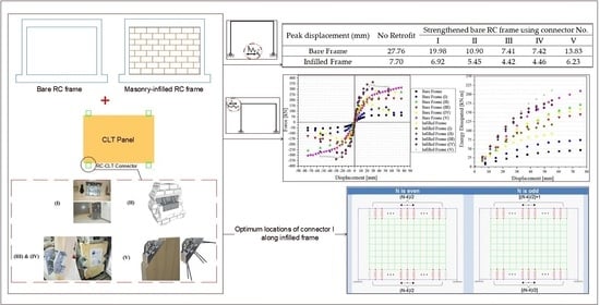
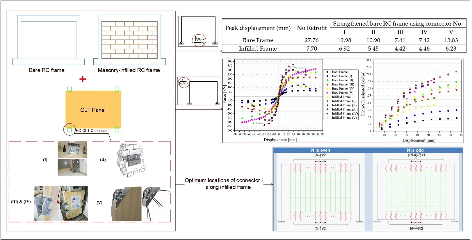
To better understand the participation of the masonry infill, the numerical analysis began by evaluating the bare RC frame, not considering the masonry infill, in two situations: original and strengthened by the CLT panel. 
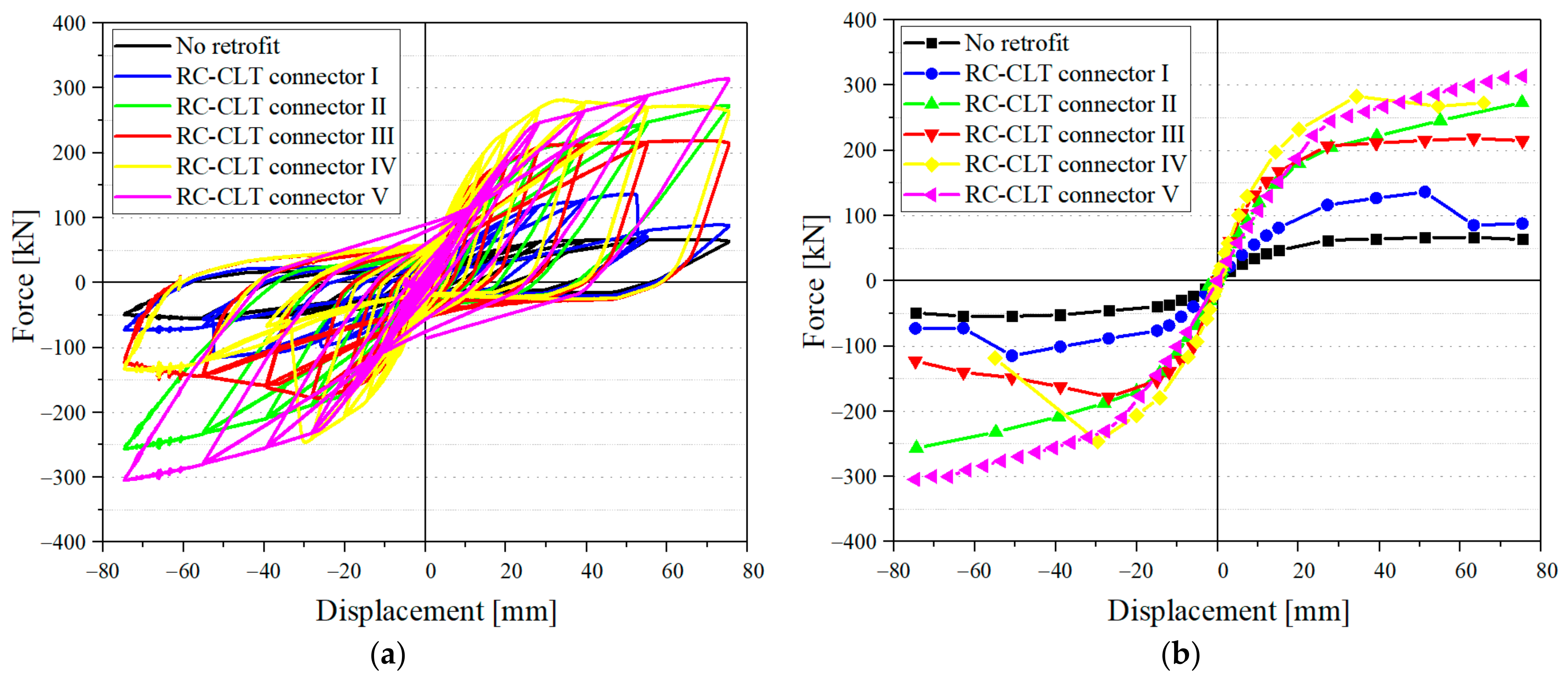
Figure 13 shows cyclic curves (a) and backbone curves (b) of the bare frame and bare frame strengthened by the CLT panel, considering the five selected connectors.
As discussed before, the main contribution of the CLT panel under cyclic loading depends on the connectors used, and Figure 13 clearly demonstrates how using different connectors leads to distinct performances. According to 
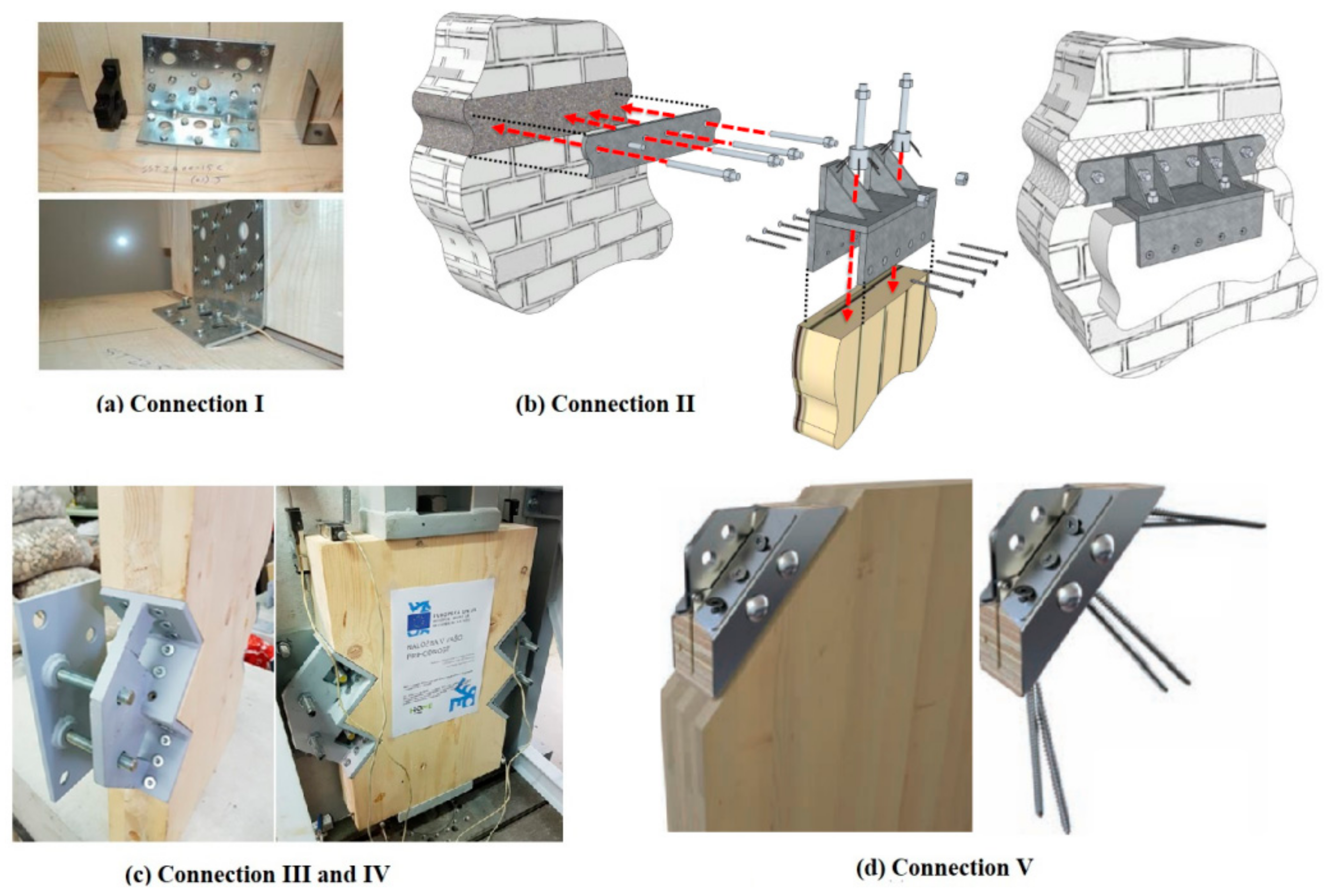
Figure 13b, connector V has the highest ultimate strength, mainly owing to the highest nonlinear stiffness with the lowest degradation, while connector IV displays the highest elastic stiffness. Moreover, connector V seems to be the best in terms of pinching effect and, consequently, higher energy dissipation. On the other hand, considering all criteria, the angle bracket (connector I) has the lowest contribution. This connection is the only one presenting strength impairment, ignoring the slight decrease observed in connector IV. Connector IV, with 8.8 grade rods, has a peak strength around 20% greater than connector III, which is identical, but the rod grade is 4.6.
The questions that arise are whether adopting a more expensive connector results in a higher strength, like connectors III and IV, whether a simple connector gives a better response or whether less expensive connectors do, like connectors I and V, and finally which one of two crucial design criteria of connection, including geometry and mechanical properties, plays a more effective role in seismic actions. This is where an optimization process needs to be established to remove ambiguities, as will be discussed in the next section.
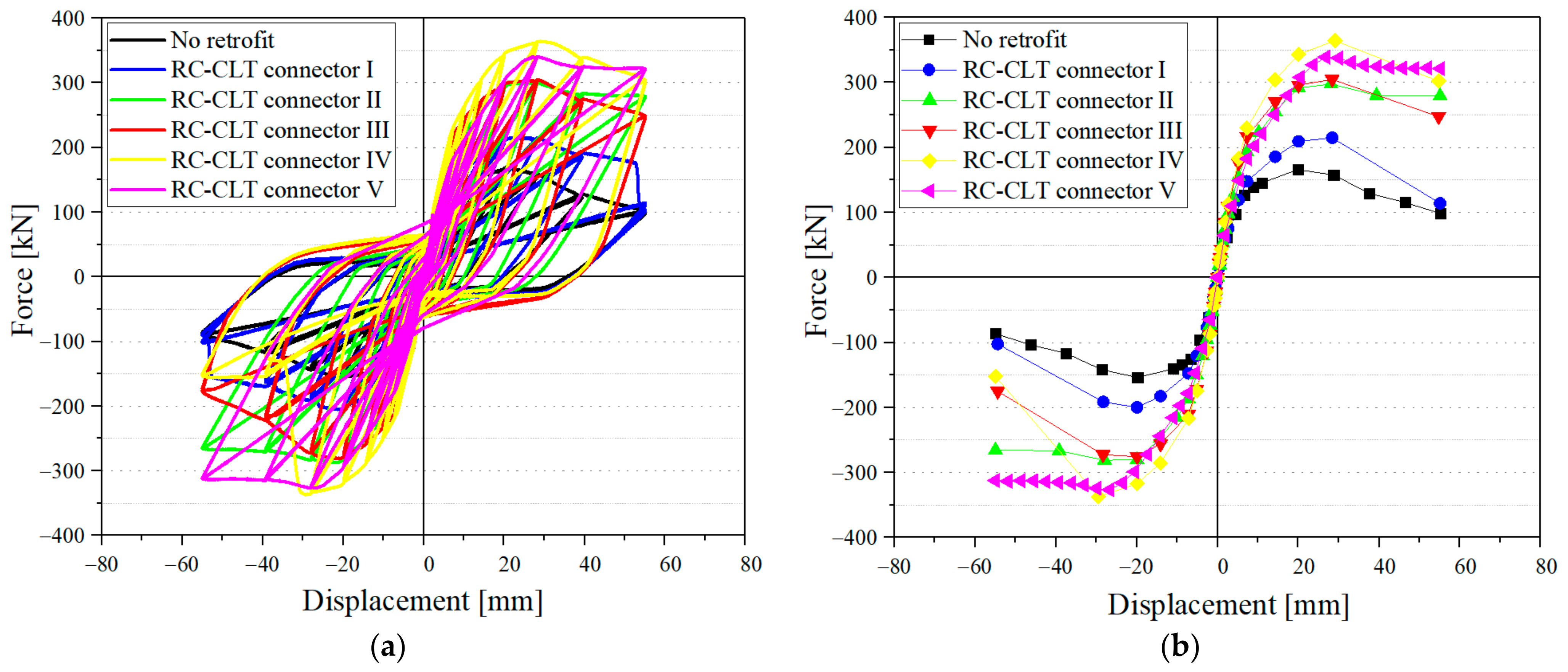
Figure 14 shows the masonry-infilled RC frame and the same frame strengthened by a CLT panel fixed with the five selected connectors. Connector IV has the highest strength and elastic stiffness.
This impact can be clearly understood when for all connectors strength impairment is observed, unlike the bare frames where only connector I underwent a decrease after its peak. However, based on Table 2, it can be concluded that masonry infills generally help the frames to have greater load-carrying capacity. In spite of the effect of masonry infills on increasing the peak strengths, the positive effect of the CLT panels on the frames decreases, meaning that CLT panels with connectors I to V have increased peak strength of the bare frame in the rate of 2.04, 4.08, 3.27, 4.22, 4.69, respectively, whereas these rates for the infilled frames are 1.27, 1.77, 1.80, 2.15, 2.01, respectively. Given these rates, connector V and II experience the most drops from the presence of the infill. Moreover, the ratio between peak strength of infilled and bare fames is 2.52, and the ratios between peak strength of infilled and bare frames strengthened by connectors I to V are, respectively, 1.57, 1.10, 1.39, 1.29, 1.08. This confirms the claim that the infill results in a lower strength improvement in bare frames having more peak strength.
The ratio between the rods yielding strength used in connectors IV (640 MPa) and III (240 MPa) is 2.66, and the ratio between the ultimate strength of rods used in connectors IV (800 MPa) and III (400 MPa) is two. Nevertheless, the improvement of peak strength is 227% and 322% for the bare RC frame strengthened by CLT with connectors III and IV, respectively, and 80% and 115% in the case of the infilled RC frame connected to the CLT panel by connectors III and IV, respectively. As a result, the ratio between cyclic response improvement of connectors III and IV for the bare RC frame (1.41) and the infilled RC frame (1.44) is less than the ratio of the rod strength. Connector IV presented the highest strength and the highest unloading stiffness, and therefore it is expected to have higher energy dissipation.
All connectors, with the exception of the angle brackets (connection I), have a ductile behavior with no significant strength impairment in the inelastic range.
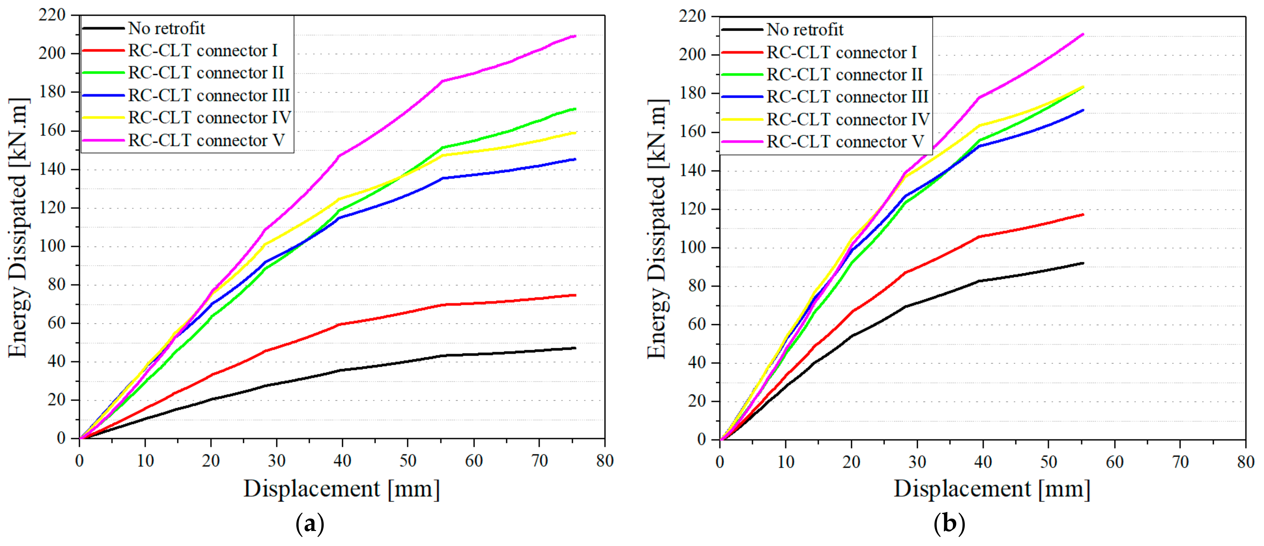
 Figure 15 and Table 3 represent the energy dissipation (ED) for each displacement, and the final ED for all cases, bare RC frame and infilled RC frame, considered in this study.
According to Table 3, the X-RAD connector demonstrated by far the best final ED for both bare and infilled frames, followed by connectors II, IV, III, and finally I. Although there are some similarities between the order of ED and that of strength demand (Table 2), they do not necessarily follow the same order. This proves that a stronger connection may not dissipate more energy. Connectors III and IV have great potential to dissipate energy in the infilled frames until the half of ultimate displacement. Connector IV only dissipates around 5% more energy than connector III, and it is worth investigating whether replacing rods 4.6 to 8.8 economically justifies this small increase of ED. On the other hand, it is proven that four angle brackets attaching the CLT panel to the RC elements give to the bare and infilled frame an increase of 56.25% and 30.76% in ED, respectively, which seems to be considerable with regards to its simplicity. Except the best dissipating connectors (V), all others took advantage of the masonry infill contribution to the overall cyclic improvement of the RC frame (Figure 15a,b). With the presence of the masonry infill, the bare RC frame and those strengthened using connectors I to V, have an improvement of 95.27%, 56.98%, 7.06%, 18.05%, 15.48%, and 0.84% of ED. Similarly to what was observed in strength demand, it can be concluded that the stronger a connector is, the less the masonry infill can contribute to dissipate energy.
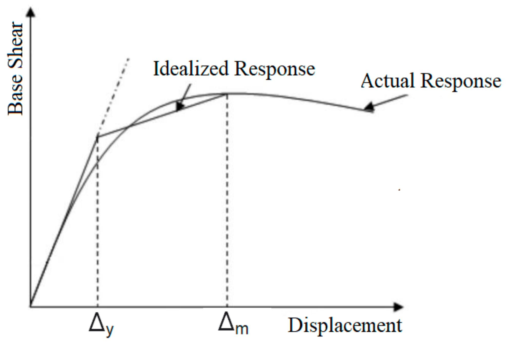
An important parameter used to assess the seismic performance of structural systems is structural ductility; as suggested by FEMA 2004 [28], this can be expressed as
R = Δ m / Δ y
where Δy and Δm are yielding and ultimate displacements, respectively, measured from the backbone curves presented above, corresponding to the displacements in which yielding and the first failure in a RC element, respectively, happen as shown in Figure 16. These amounts are achieved by calculating the equivalent bilinear curve, which has the same area as the envelope curve [28]. A nonlinear static analysis (Pushover) was carried out to extract the peak strength, corresponding to the ultimate displacement every frame undergoes.
Generally speaking, as shown in Table 4, adding CLT panels to both bare and infilled fames increases the ductility factor of the frame, regardless of the type of RC-CLT connector. Previously it was shown that connector V allowed the most energy dissipation and presented higher strength capacity for the strengthened masonry-infilled RC frame. However, as shown in Table 4, the RC frame, both bare and infilled, with these connectors resulted in the lowest ductility factor among all connectors. The main reason stems from the fact that the increase of strength and stiffness made by the connectors after yielding is more than that before the yielding, which leads to a higher yielding point in the equivalent bilinear curve and thus smaller ductility. Generally, it can be stated that a stronger connection does not necessarily increase the ductility of the frame. Considering this point, a higher ductility confirms the nonlinear deformations of connectors, while a lower ductility may not mean the connector would not be used in cyclic actions. A similar behavior is also found by comparing connectors III and IV. The latter has threaded rods with higher-grade rods but has less ductility than the former both in the bare and infilled frame. Another finding of the table is that the infill decreases the ductility in the all frames infilled with masonry due to its premature failures happening before other elements; however, infills increase the initial stiffness of frames, which causes the yielding displacement of the equivalent bilinear curve to decrease and the ductility to slightly increase.
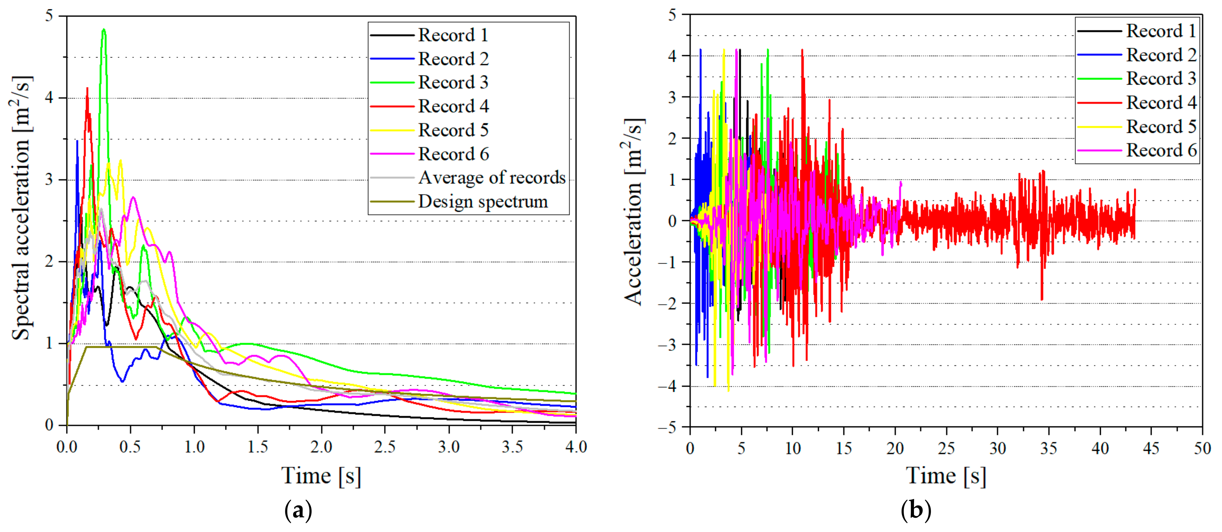
Finally, with the aim to evaluate the seismic responses of the RC frames considering their dynamic characteristics, a set of six earthquake records were selected, as shown in Table 5.
Based on Eurocode 8 [30], first, the average spectral acceleration of all records was matched with the design spectrum (Figure 17a) such that the peak of the latter per the former resulted in the scaling factor. Then, all the records in Table 5 were multiplied by this factor (Figure 17b). Finally, after applying these records scaled on the RC frames, peak displacements were taken, and the response improvements made by the CLT strengthening technique are registered in Table 6.
According to Table 6, some important results can be drawn. All frames reinforced with the CLT panel have less displacement than the frame unstrengthened, no matter which kind of connector is adopted, which prevents in turn common brittle failures observed in existing masonry-infilled RC-framed buildings, namely failure of the beam-column joint due to shear transferred from infill and out-of-plane movement of infill.
To make a comparison between the masonry-infilled frame and CLT-infilled frame (or bare frame strengthened by CLT), the table shows also that the masonry infill reduces the lateral displacement of the RC frame more than what the CLT panel as an infill does, except for the panels attached to the frame by connectors III and IV. However, masonry infill undergoes major damage at the end of loading, requiring a substantial repair or even replacement, while in the strengthened frame only connectors that encounter plastic deformation need to be replaced, considering CLT panels remain undamaged due to elastic deformation. In the RC buildings, what makes the CLT preferable to masonry as an infill is that repairing or replacing masonry infill is disruptive for the building occupant, requiring them to be relocated, while RC-CLT connectors are quickly installed, resulting in the least disruption.
As opposed to the cyclic analyses, where connector III provided less strength in the frame than connectors II, IV, and V, in all seismic records, connectors III and IV result in the greatest displacement reduction, followed by connectors II, V, and I. Connectors III and IV result in a similar improvement, though connector IV takes advantage of having stronger rods than connector III. This order of connector effectiveness in seismic mitigation of the frame is not affected by record characteristics, such as duration and frequency content, but is highly dependent on the connector’s split/uplift stiffness. Table 7 displaying the fundamental frequencies of the frame, is presented to show the lateral stiffness of the frame after adding CLT.
It was shown than adding CLT increases the frame fundamental frequency and as a result increases the frame stiffness, thus reducing displacement. Thus, there is a direct relationship between fundamental frequency of a frame and the split/uplift springs that represent the RC-CLT connector.

4.2. Optimum Number and Arrangement of Connectors

As shown in the previous section, connector II has the greatest effect on load-carrying capacity, and connector V dissipates the highest energy, while connector I has the lowest effect on both criteria. On the other hand, connectors II and V have complicated details and components, and connector I is a simple angle bracket widely used in timber engineering. The question that arises is whether it is recommended to adopt a strong, complex, and expensive connector or a relatively common, simple, and inexpensive one. One way to support address this question is to determine the number and type (strong or simple) that have the greatest contribution to the frame strengthened by a CLT panel for the same seismic behavior. Therefore, an optimization process needs to be established to address the problem of determining how many simple RC-CLT connectors (I) are required to present the same seismic response as the strongest one (connector V).
In this process of finding the optimum number, another question involves the configuration of connectors. For instance, it is clear that installing a connector on the middle of a column is different compared to installation on the middle of a beam. Consequently, the optimization process should consider finding the optimum number and arrangement of simple connectors, providing a similar behavior to using four V connectors. The optimization process is based on searching all possible arrangements and numbers of weak connectors, starting from the minimum number of four. If the best arrangement of connectors does not match the response of four V connectors, one connector is added to the weak ones, and the searching process is performed again. Once the matching occurs with a certain number of weak connectors, the algorithm stops. The simple and strong connectors adopted are, respectively, AE116 angle bracket (connector I) and X-RAD (connector V), and the seismic performance as a matching criterion or goal function is the load-carrying capacity or maximum strength of the masonry-infilled RC frames strengthened by the CLT panel.
Table 8 shows that 16 angle brackets are required to reach to the peak strength (340.5 kN) corresponding to the infilled frame strengthened by 4 X-RAD.
As mentioned previously, another aim of the optimization process is to find the best arrangement of a certain number of AE116. In this regard, Table 9 presents the optimum locations of angle brackets used to attach the CLT panel to the masonry-infilled RC frame.
The table summarizes the best configurations in terms of the lowest goal function, referring the lowest difference between strength capacity of the frame strengthened by 4 X-RAD and those strengthened by AE116. The symbols used in the table, U, D, L, R, represent respectively the upper beam, lower beam, left column, and right column. A combination of the symbols, for example, 3U + 1L + 1R, expresses that three, one, and one AE116 were used in the upper beam, left column, and right column, respectively, to attach the CLT panel to the RC frame. The configurations highlighted in green indicate the optimum arrangement of AE116 at a certain number.
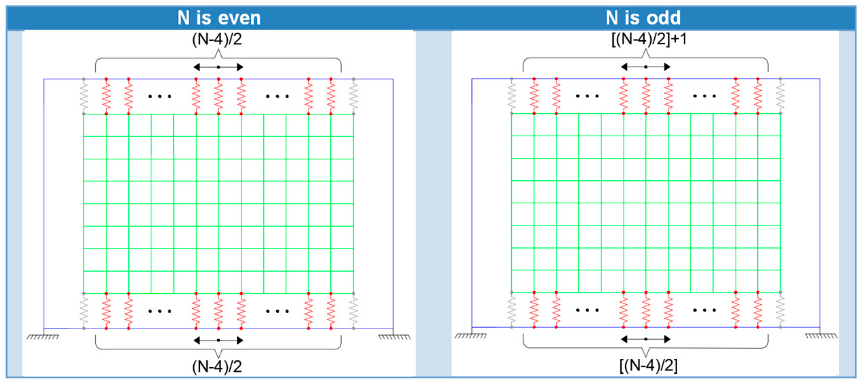
Analyzing the table, the optimum configuration is the one where ABs are distributed along the upper and lower beams. That is, for an even number of ABs, it is recommended to use half of them along the upper beam and another half along the lower beam, while, for an odd number of ABs, the upper beam needs to have one more AB than the lower beam, as shown schematically in Figure 18. Another finding is that simulations have proven that the ABs distribution along the beams should be started from the middle, moving to the corners where the beams and columns connect. Moreover, given the four connectors in the corners, it is better for connectors to be an equal distance from each other.

5. Conclusions

The present work mainly focuses on comparing a set of connectors, ranging from the weak and cheap to strong, complicated, and flexible ones, with reference to their roles in seismic mitigation of a masonry-infilled RC frames strengthened with a CLT panel. The first aim is to determine the best and worst connectors in terms of seismic criteria, consisting of variations of strength and stiffness through the loading, along with their deterioration, pinching effect, ED, and ductility, by evaluating the frame under pseudo-static and dynamic loadings. Having recognized and classified connectors, we aimed to determine which type of group connectors, including more weak connectors or less strong ones, results in frame being strengthened to a higher level of seismic satisfaction, through adopting a searched-based optimization algorithm. The later evaluation is accompanied with drawing a pattern of optimal placement of a connector through the RC elements. The noteworthy findings are as follows:
  • Comparing results made in different analyses between the frames attached to the CLT using different connectors, the following are highlighted: I) Peak strength in cyclic analysis depends on the ultimate strength of the connector. II) The energy dissipated depends on the inelastic stiffness and its degradation. III) The ductility factor depends on the plastic deformation and strength degradation. IV) The fundamental frequency of the frames and their seismic responses depend on the elastic stiffness of RC-CLT connectors.
  • Mechanical properties, e.g., rod strength, do not play a significant role in cyclic strength, energy dissipation, structural ductility, and seismic displacement, but the changing of geometry of connectors, such as rod diameters, the distance between rods, and rod directions, results in more progress in the responses.
  • Infills increase peak strengths but reduce the effect of CLT panels on frames; however, stronger connectors alleviate the contribution of masonry infill to dissipating energy. Even by strengthening the frame with CLT, force-deformation in the masonry infill shows a strength and stiffness deterioration. as it fails before peak strength of base shear of the main frame, reducing the frame ductility.
  • It was shown that infilled frames present less ductility than bare frames. CLT panels increase the ductility of bare/infilled frames, though a stronger connector does not necessarily lead to a higher ductility factor. Higher ductile connectors are appropriate for nonlinear deformations, but there are strong connectors with brilliant seismic behavior that do not present a high ductility factor.
  • To find the highest strength capacity of the frame through the arrangement of angle brackets, the connectors need to be distributed equally along the upper and lower beam, with equal spacing. This distribution should start from the middle of beam, moving to the corners of the frame.

Author Contributions

Conceptualization, Z.M. and J.M.B.; methodology, Z.M. and J.M.B.; software, Z.M.; validation, Z.M., E.P. and J.M.B.; formal analysis, Z.M.; writing—original draft preparation, Z.M.; writing—review and editing, E.P., J.M.B. and P.B.L.; supervision, E.P. and J.M.B.; project administration, J.M.B. and P.B.L.; funding acquisition, J.M.B. and P.B.L. All authors have read and agreed to the published version of the manuscript.

Funding

This research was funded by FCT project Timquake (POCI-01-0145-FEDER-032031) and FCT individual PhD grant (UI/BD/153681/2022).

Institutional Review Board Statement

Not applicable.

Informed Consent Statement

Not applicable.

Data Availability Statement

Not applicable.

Acknowledgments

The financial support of the Portuguese Science Foundation (Fundação de Ciência e Tecnologia, FCT) within the scope of the Timquake project POCI-01-0145-FEDER-032031 and the PhD grant UI/BD/153681/2022 is gratefully acknowledged.

Conflicts of Interest

The authors declare no conflict of interest.

References

  1. Cavaleri, L.; Di Trapani, F. Cyclic response of masonry infilled RC frames: Experimental results and simplified modeling. Soil Dyn. Earthq. Eng. 2014, 65, 224–242. [Google Scholar] [CrossRef]
  2. Paulo, M.F.; Neto, M.F.; Dias, J.E.; Lourenço, P.B. Behavior of masonry infill panels in RC frames subjected to in plane and out of plane loads. In Proceedings of the 7th International Conference AMCM 2011: Analytical and New Concepts in Concrete and Masonry Structures, Kraków, Poland, 13–15 June 2011. [Google Scholar]
  3. Brandner, R.; Flatscher, G.; Ringhofer, A.; Schickhofer, G.; Thiel, A. Cross laminated timber (CLT): Overview and development. Eur. J. Wood Wood Prod. 2016, 74, 331–351. [Google Scholar] [CrossRef]
  4. Hristovski, V.; Mircevska, V.; Dujic, B.; Garevski, M. Comparative dynamic investigation of cross-laminated wooden panel systems: Shaking-table tests and analysis. Adv. Struct. Eng. 2017, 21, 1421–1436. [Google Scholar] [CrossRef]
  5. Espinoza, O.; Trujillo, V.R.; Mallo, M.F.L.; Buehlmann, U. Cross-Laminated Timber: Status and Research Needs in Europe. BioResources 2015, 11, 281–295. [Google Scholar] [CrossRef]
  6. Muszynski, L.; Larasatie, P.; Guerrero, J.E.; Albee, R. Global CLT industry in 2020: Growth beyond the Alpine Region. In Proceedings of the 63rd International Convention of Society of Wood Science and Technology, Portorož, Slovenia, 12–15 July 2020. [Google Scholar]
  7. Sustersic, I.; Dujic, B. Seismic Strengthening of Existing Concrete and Masonry Buildings with Crosslam Timber Panels. In Materials and Joints in Timber Structures; RILEM Bookseries; Springer: Dordrecht, The Netherlands, 2014; Volume 9. [Google Scholar] [CrossRef]
  8. Boggian, F.; Tardo, C.; Aloisio, A.; Marino, E.M.; Tomasi, R. Experimental Cyclic Response of a Novel Friction Connection for Seismic Retrofitting of RC Buildings with CLT Panels. J. Struct. Eng. 2022, 148, 04022040. [Google Scholar] [CrossRef]
  9. Gavric, I.; Fragiacomo, M.; Ceccotti, A. Cyclic Behavior of CLT Wall Systems: Experimental Tests and Analytical Prediction Models. J. Struct. Eng. 2015, 141, 04015034. [Google Scholar] [CrossRef]
  10. Casagrande, D.; Rossi, S.; Sartori, T.; Tomasi, R. Proposal of an analytical procedure and a simplified numerical model for elastic response of single-storey timber shear-walls. Constr. Build. Mater. 2016, 102, 1101–1112. [Google Scholar] [CrossRef]
  11. D’Arenzo, G.; Seim, W.; Fossetti, M. Experimental characterization of a biaxial behaviour connector for CLT wall-to-floor connections under different load directions. Constr. Build. Mater. 2021, 295, 123666. [Google Scholar] [CrossRef]
  12. Scotta, R.; Marchi, L.; Trutalli, D.; Pozza, L. A Dissipative Connector for CLT Buildings: Concept, Design and Testing. Materials 2016, 9, 139. [Google Scholar] [CrossRef] [PubMed] [Green Version]
  13. Latour, M.; Rizzano, G. Seismic behavior of cross-laminated timber panel buildings equipped with traditional and innovative connectors. Arch. Civ. Mech. Eng. 2017, 17, 382–399. [Google Scholar] [CrossRef]
  14. Izzi, M.; Casagrande, D.; Bezzi, S.; Pasca, D.; Follesa, M.; Tomasi, R. Seismic behaviour of Cross-Laminated Timber structures: A state-of-the-art review. Eng. Struct. 2018, 170, 42–52. [Google Scholar] [CrossRef]
  15. Instituto Nacional de Estatística—Estatísticas da Construção e Habitação. Construction and Housing Statistics-2019. 2020. Available online: https://www.ine.pt/xurl/pub/443821545 (accessed on 10 October 2022).
  16. Silva, L.M.; Vasconcelos, G.; Lourenço, P.B.; Akhoundi, F. Seismic performance of Portuguese masonry infill walls: From traditional systems to new solutions. In Proceedings of the COMPDYN Proceedings, Crete, Greece, 24–26 June 2019; Volume 2. [Google Scholar] [CrossRef]
  17. Silva, L.M.; Vasconcelos, G.; Lourenço, P.B. Innovative systems for earthquake-resistant masonry infill walls: Characterization of materials and masonry assemblages. J. Build. Eng. 2021, 39, 102195. [Google Scholar] [CrossRef]
  18. DIN 1052:2008; Entwurf, Berechnung und Bemessung von Holzbauwerken—Allgemeine Emessungsregeln und Bemessungsregeln für den Hochbau. Deutsches Institut für Normung: Berlin, Germany, 2008.
  19. EN 338:2003; Structural Timber. Strength Classes. C. (European C. for Standardization). CEN (European Committee for Standardization): Brussels, Belgium, 2003.
  20. Bodig, J.; Jayne, B. Mechanics of Wood and Wood Composites; Van Nostrand Reinhold: New York, NY, USA, 1982. [Google Scholar]
  21. Matos, F.T.; Branco, J.M.; Rocha, P.; Demschner, T.; Lourenço, P.B. Quasi-static tests on a two-story CLT building. Eng. Struct. 2019, 201, 109806. [Google Scholar] [CrossRef]
  22. Sustersic, I. Strengthening of Buildings with Cross-laminated Timber Plates; University of Ljubljana: Ljubljana, Slovenia, 2017. [Google Scholar]
  23. Polastri, A.; Angeli, A. An innovative connection system for CLT structures: Experimental-numerical analysis. In Proceedings of the World Conference on Timber Engineering (WCTE), Quebec City, QC, Canada, 10–14 August 2014. [Google Scholar]
  24. SAP 2000 14.2.2 [Computer Software]; Computer & Structures: Berekley, CA, USA, 2016.
  25. Polastri, A.; Giongo, I.; Piazza, M. An Innovative Connection System for Cross-Laminated Timber Structures. Struct. Eng. Int. 2017, 27, 502–511. [Google Scholar] [CrossRef]
  26. Blass, H.; Fellmoser, P. Design of solid wood panels with cross layers. In Proceedings of the 8th World Conference on Timber Engineering, Lahti, Finland, 14–17 June 2004; Volume 14. [Google Scholar]
  27. FEMA. Interim Protocols for Determining Seismic Performance Characteristics of Structural and Nonstructural Components Through Laboratory Testing; FEMA 461; FEMA: Washington, DC, USA, 2007. [Google Scholar]
  28. Federal Emergency Management Agency (FEMA). NEHRP Recommended Provisions for Seismic Regulations for New Buildings and Other Structures; FEMA 450; FEMA: Washington, DC, USA, 2004. [Google Scholar]
  29. Ancheta, T.; Darragh, R.; Stewart, J.; Seyhan, E.; Silva, W.; Chiou, B.; Wooddell, K.; Graves, R.; Kottke, A.; Boore, D.; et al. PEER 2013/03: PEER NGA-West2 Database. Pacific Earthquake Engineering Research Center (PEER). 2013. Available online: http://peer.berkeley.edu/publications/ (accessed on 10 October 2022).
  30. EN 1998-3:2005; Eurocode 8: Design of Structures for Earthquake Resistance—Part 3: Assessment and Retrofitting of Buildings. European Committee for Standardization: Brussels, Belgium, 2005.
Figure 1. The selected RC frame: (a) dimensions, (b) cross-sections and steel reinforcements (Silva et al. [16]).
Buildings 12 02009 g001
Figure 2. The adopted masonry infill and its components.
Buildings 12 02009 g002
Figure 3. Principal directions in timber.
Buildings 12 02009 g003
Figure 4. The five CLT-to-RC frame connectors considered: (a) angle bracket AE116; (b) steel strap and bracket; (c) steel bracket and rods; (d) X-RAD.
Buildings 12 02009 g004
Figure 5. Calibration of the RC frame model based on experiments performed by Silva et al. [16]: (a) test setup; (b) base shear (kN) versus drift (mm).
Buildings 12 02009 g005
Figure 6. Schematic drawing of the infilled frame in modeling.
Buildings 12 02009 g006
Figure 7. Calibration of the infilled RC frame model based on experiments performed by Silva et al. [16]: (a) test setup; (b) base shear (kN) versus drift (mm).
Buildings 12 02009 g007
Figure 8. Calibration of the cyclic response of connector I: (a) Split; (b) Uplift.
Buildings 12 02009 g008
Figure 9. Uplift and lateral force versus deformation in connection II [22].
Buildings 12 02009 g009
Figure 10. Calibration of the cyclic response: (a) connection III; (b) connection IV.
Buildings 12 02009 g010
Figure 11. Force-deformation calibration of the connection V springs [25]: (a) horizontal loading; (b) vertical Loading.
Buildings 12 02009 g011
Figure 12. Schematic drawing of the bare frame reinforced with CLT panel in modeling.
Buildings 12 02009 g012
Figure 13. Base shear versus top displacement for the bare RC frame and the frame attached to the CLT panel using different connectors: (a) hysteresis curves, (b) backbone curves.
Buildings 12 02009 g013
Figure 14. Base shear versus top displacement for the infilled RC frame and the frame attached to the CLT panel using different connectors: (a) hysteresis curves, (b) backbone curves.
Buildings 12 02009 g014
Figure 15. Accumulated total energy versus displacement: (a) bare RC frame; (b) infilled RC frame.
Buildings 12 02009 g015
Figure 16. Yielding and ultimate displacements in the equivalent bilinear curve.
Buildings 12 02009 g016
Figure 17. Scaling the records in Table 4: (a) spectral acceleration matching, (b) the records scaled.
Buildings 12 02009 g017
Figure 18. Optimum arrangement of ABs connectors along the masonry-infilled RC frames.
Buildings 12 02009 g018
Table 1. Mechanical characteristics of the CLT panel.
PropertyValueReference
EL11,000 N/mm2EN 338:2003 [19]
ER370 N/mm2
ET370 N/mm2
GLR688 N/mm2
GLT688 N/mm2
GRT68.8 N/mm2DIN 1052 [18]
vLR0.02Bodig et al. [20]
vLT0.02
vRT0.3
Table 2. Peak strengths (kN) in bare and infilled RC frames strengthened using the five selected connectors.
OriginalStrengthened by CLT Panel Using Connector No.
IIIIIIIVV
Bare RC Frame67137273.3219282.7314.1
Infilled RC Frame169.2215.6299.9304.7364.4340.6
Table 3. Final ED (kN.m) in bare and infilled frames strengthened using different connectors.
OriginalStrengthened by CLT Panel Using Connector No.
IIIIIIIVV
Bare RC Frame47.274.8171.5145.4159.2209.3
Infilled RC Frame92.2117.4183.6171.7183.9211.1
Table 4. Structural ductility factor.
OriginalStrengthened by CLT Panel Using Connector No.
IIIIIIIVV
Bare RC Frame6.206.3112.6114.189.346.28
Infilled RC Frame5.304.457.257.795.655.25
Table 5. Characteristics of the selected earthquake records [29].
No.MagnitudeMechanismYearEvent NameStation Name
16.3Normal2009L’Aquila ItalyV. Aterno—Centro Valle
27.51Strike slip1999Kocaeli TurkeyIzmit
37.37Strike slip1990Manjil IranAbbar
46.2Normal1986Kalamata Greece-01Kalamata (bsmt)
56.6Normal Oblique1981Corinth GreeceCorinth
66.5Reverse1976Friuli Italy-01Barcis
Table 6. Peak displacement (mm) in the frames under six records scaled.
OriginalStrengthened Bare RC Frame Using Connector No.
RecordBare RC FrameIIIIIIIVV
127.2519.92 (−27%)10.10 (−63%)6.51 (−76%)6.63 (−76%)12.99 (−52%)
216.619.77 (−41%)5.08 (−69%)3.7 (−78%)3.67 (−78%)6.54 (−61%)
332.4721.5 (−34%)12.11 (−63%)8.54 (−74%)8.49 (−74%)14.34 (−56%)
421.1314.99 (−29%)9.21 (−56%)6.62 (−69%)6.61 (−69%)11.79 (−44%)
532.325.12 (−22%)13.92 (−57%)9.25 (−71%)9.32 (−71%)17.93 (−44%)
636.8228.6 (−22%)14.98 (−59%)9.82 (−73%)9.77 (−73%)19.39 (−47%)
OriginalStrengthened Masonry-Infilled RC Frame Using Connector No.
RecordInfilled RC FrameIIIIIIIVV
16.615.84 (−12%)4.57 (−31%)3.64 (−45%)3.67 (−44%)5.22 (−21%)
23.493.26 (−7%)2.79 (−20%)2.32 (−34%)2.34 (−33%)3.07 (−12%)
38.387.48 (−11%)6.01 (−28%)4.93 (−41%)4.99 (−40%)6.79 (−19%)
46.365.99 (−6%)4.83 (−24%)4 (−37%)3.99 (−37%)5.46 (−14%)
510.389.37 (−10%)7.05 (−32%)5.71 (−45%)5.7 (−45%)8.18 (−21%)
610.969.6 (−12%)7.43 (−32%)5.93 (−46%)6.04 (−45%)8.63 (−21%)
Table 7. Fundamental frequencies of all frames (Hz).
OriginalStrengthened by CLT Panel Using Connector No.
IIIIIIIVV
Bare RC Frame1.702.042.733.233.292.43
Infilled RC Frame3.523.613.974.274.303.80
Table 8. Strength capacity (kN) of the masonry-infilled RC frame strengthened by CLT using ABs and X-RAD.
Angle BracketsX-RAD
No.45678910340.5
Peak Strength (kN)214215.3233.3245251.1258.9267.7
No.111213141516
Peak Strength (kN)286.3305.8312.7319.2329.9341.9
Table 9. Optimum arrangements for different angle brackets (ABs) on the masonry-infilled RC frame.
Number of AE1165Arrangement1U1L
Peak Strength (kN)215.3212.5
6Arrangement2U1L + 1R1U + 1D
Peak Strength (kN)224.4219.8233.3
7Arrangement1U + 1L + 1R3U2U + 1D1U + 1D + 1L
Peak Strength (kN)229.6226.0245.0241.4
8Arrangement2U + 1L + 1R2L + 2R4D2U + 2D1U + 1L + 1R + 1D
Peak Strength (kN)226.8248.1225.3251.1245.4
9Arrangement5U3U + 1L + 1R1U + 2L + 2R3U + 2D2U + 1L + 1R + 1D
Peak Strength (kN)243.8252.2252.0258.9259.1
10Arrangement2U + 1L + 1R + 2D3L + 3R4U + 2D3U + 3D2U + 1R + 1L + 2D
Peak Strength (kN)260.9241.4273.7267.7260.9
11Arrangement4U + 3D3U + 1R + 1L + 2D
Peak Strength (kN)286.3276.2
12Arrangement4U + 4D3U + 1L + 1R + 3D2U + 2L + 2R + 2D
Peak Strength (kN)305.8285.3281.0
13Arrangement5U + 4D4U + 1L + 1R + 3D
Peak Strength (kN)312.7303.9
14Arrangement5U + 5D3U + 2L + 2R + 3D
Peak Strength (kN)319.2306.8
15Arrangement6U + 5D4U + 2L + 2R + 3D
Peak Strength (kN)329.9322.9
16Arrangement6U + 6D 5U + 5D + 1R + 1L
Peak Strength (kN)341.9339.3
Publisher’s Note: MDPI stays neutral with regard to jurisdictional claims in published maps and institutional affiliations.

