
Shake-Table Testing of a Cross Vault

Abstract
:1. Introduction
2. Literature Review
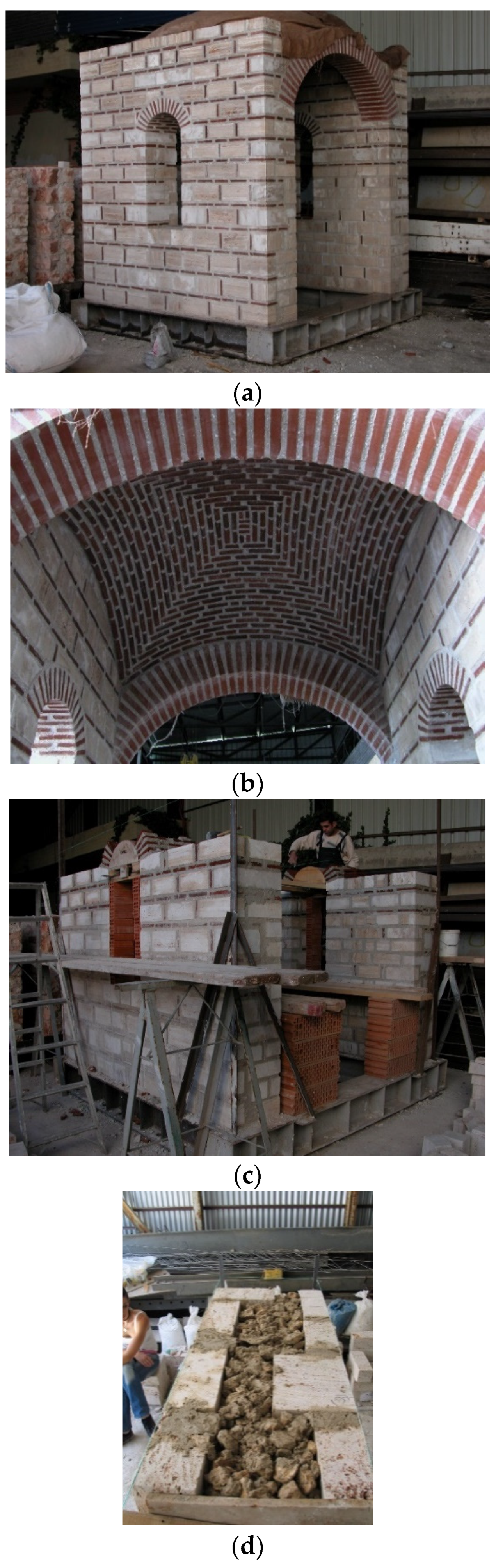
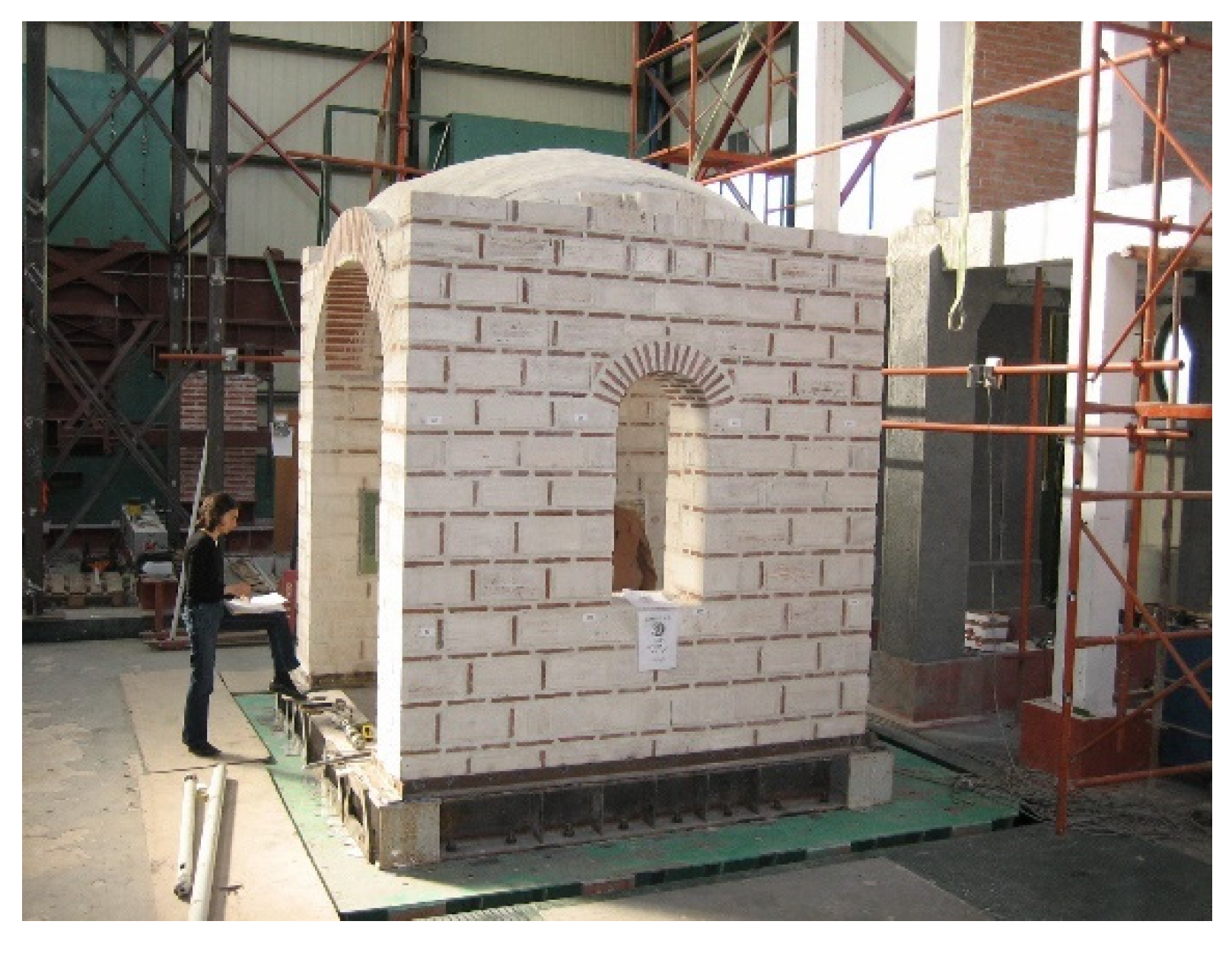
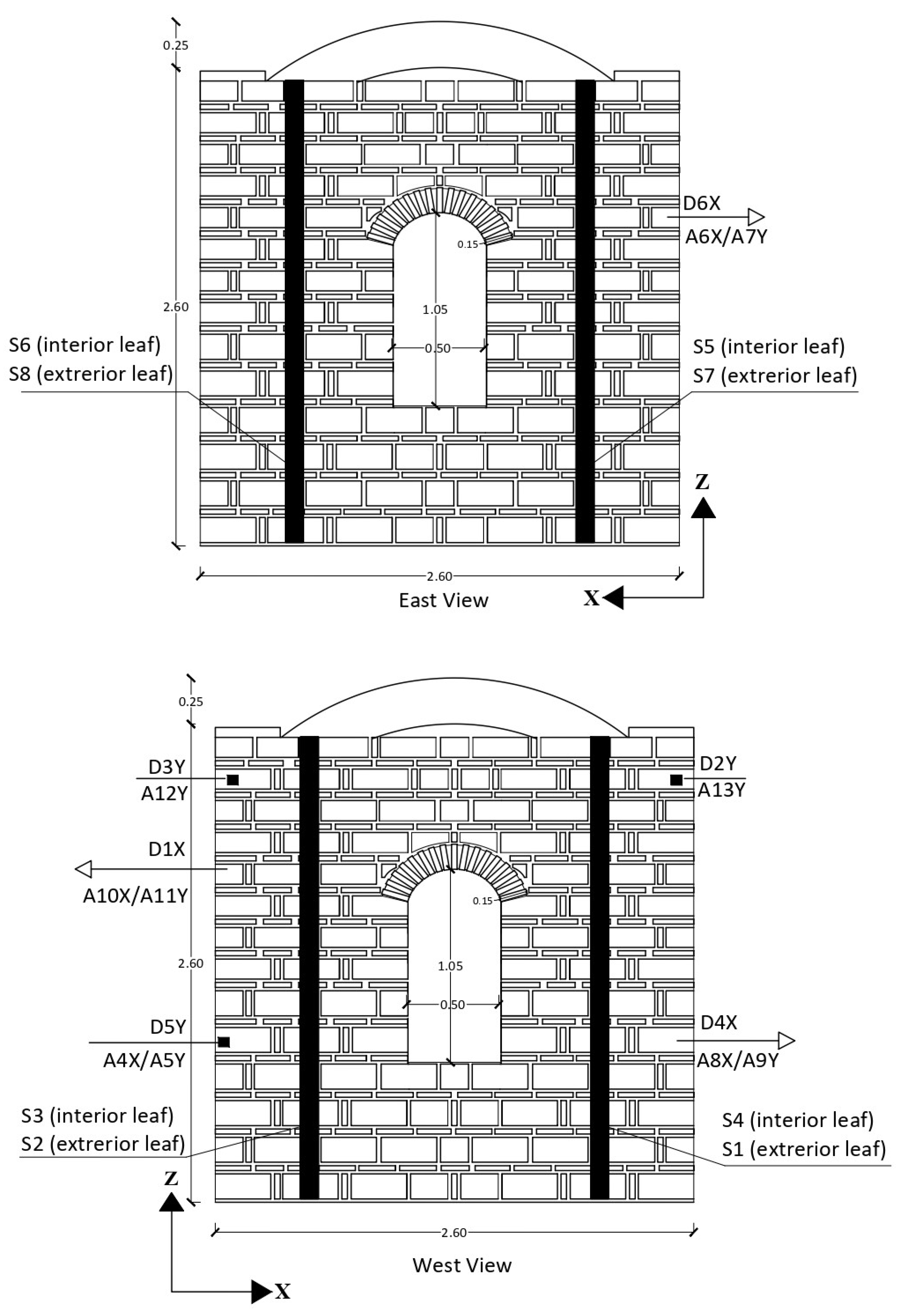
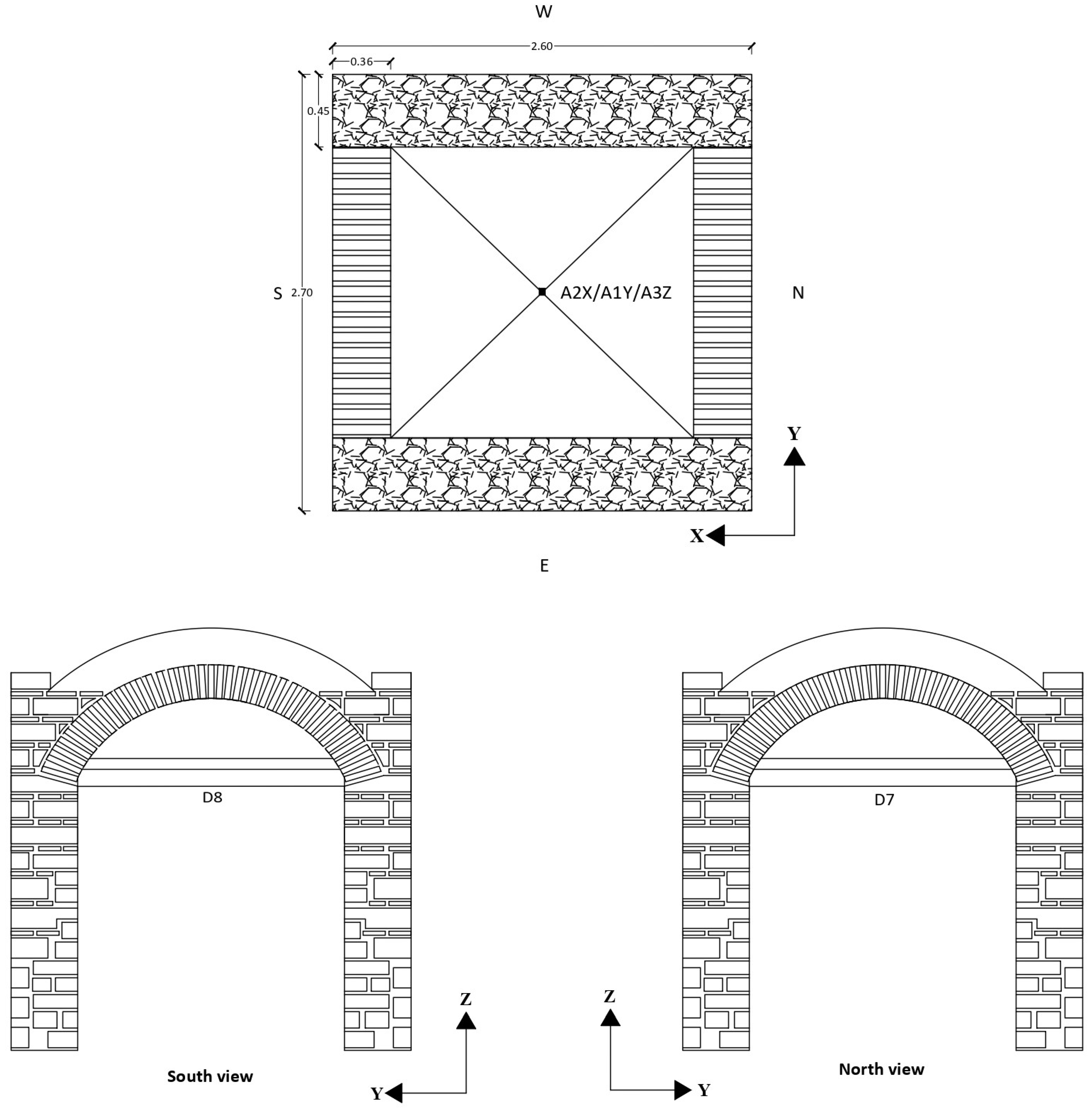
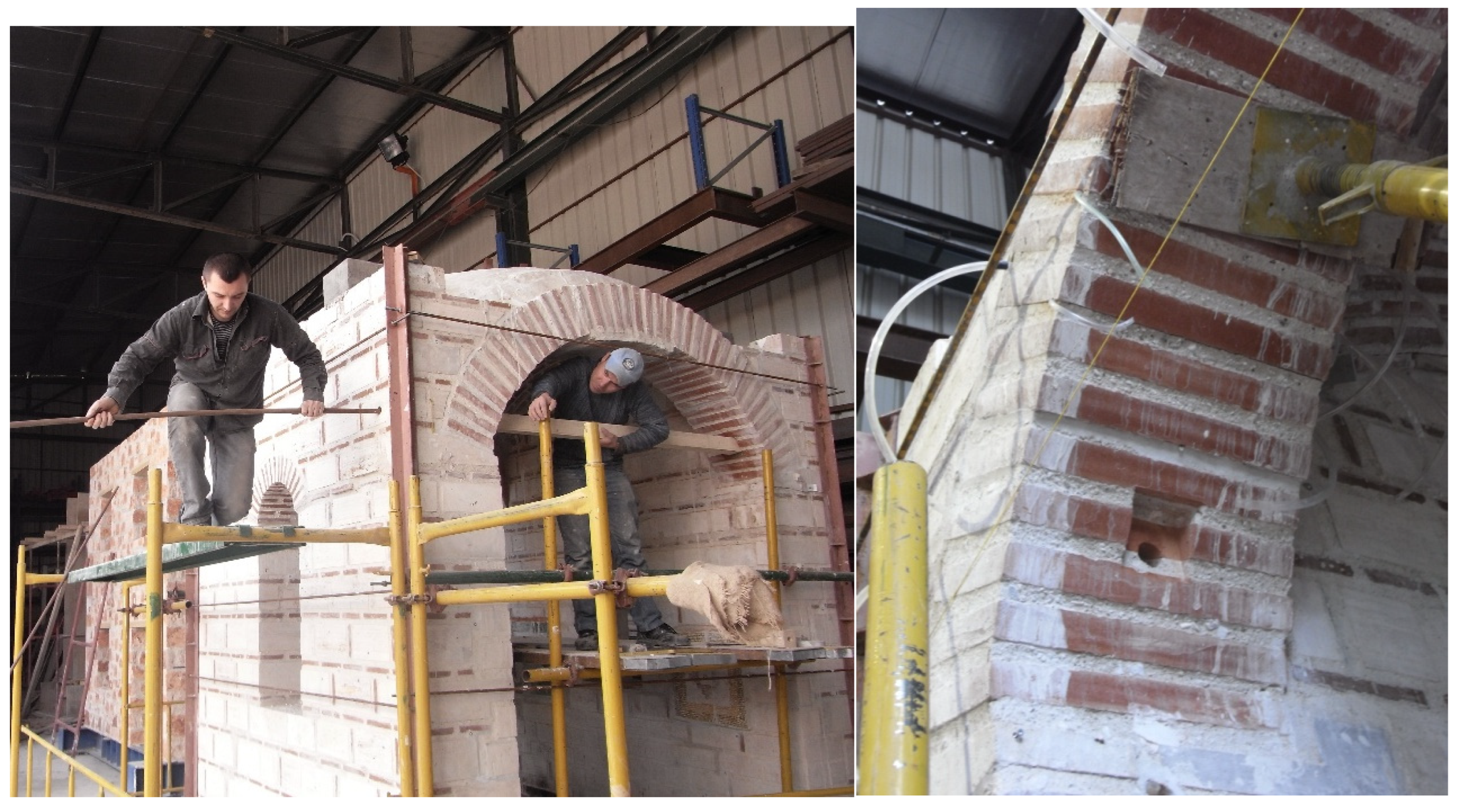
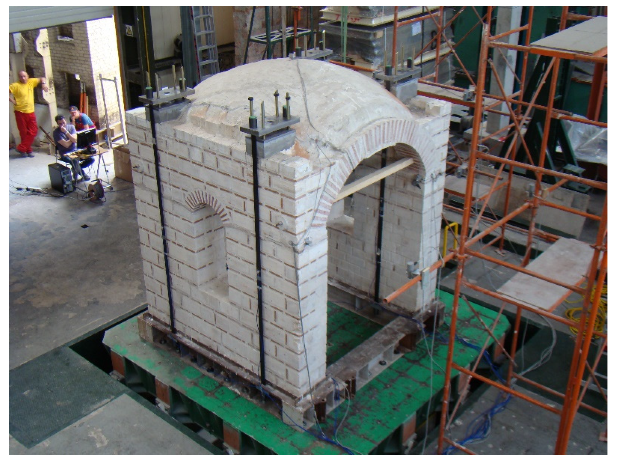
3. The Specimen, the Experimental Setup, the Instrumentation
4. Interventions
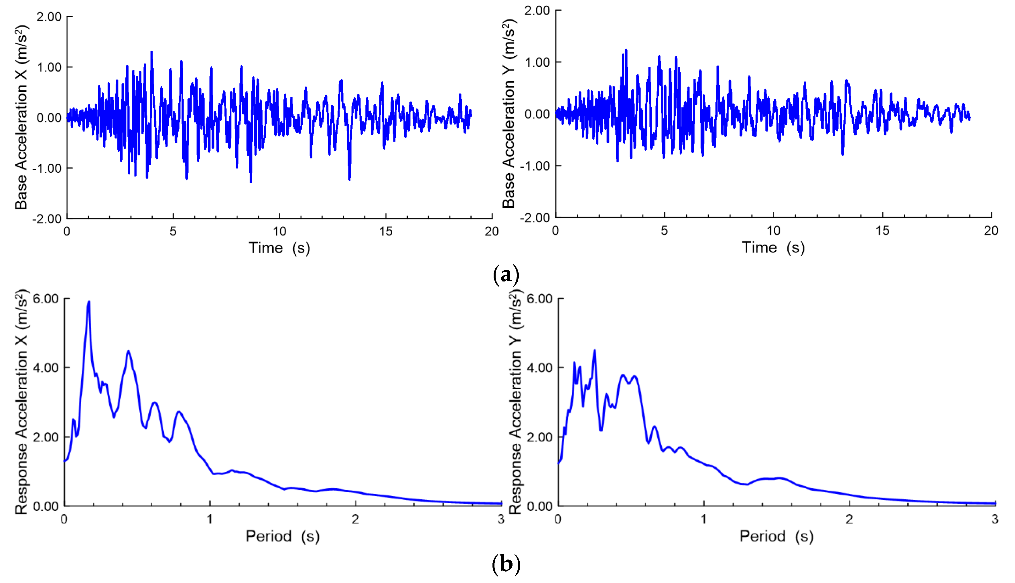
5. Performed Tests
6. Results
6.1. Dynamic Characteristics of the Subassembly
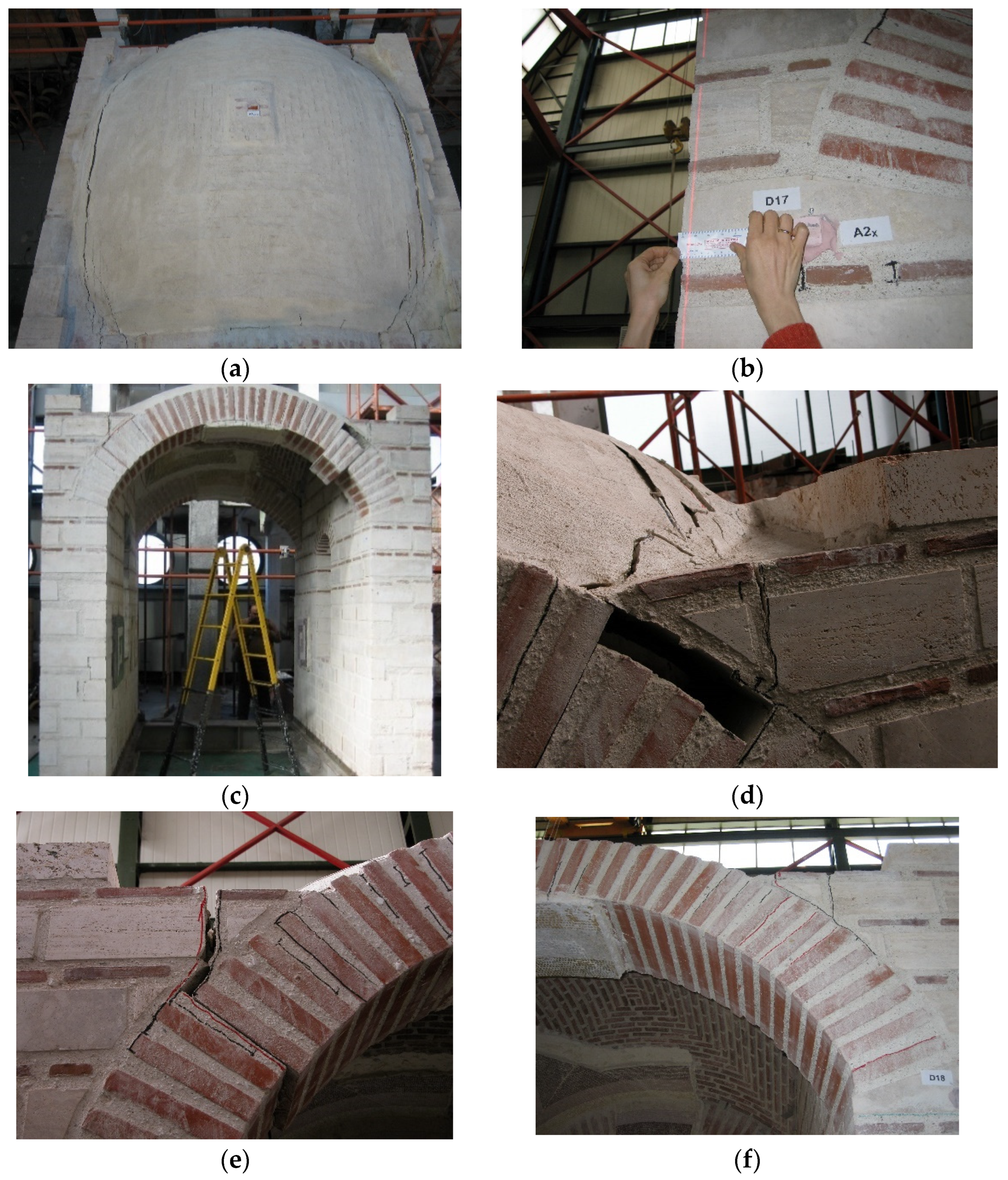
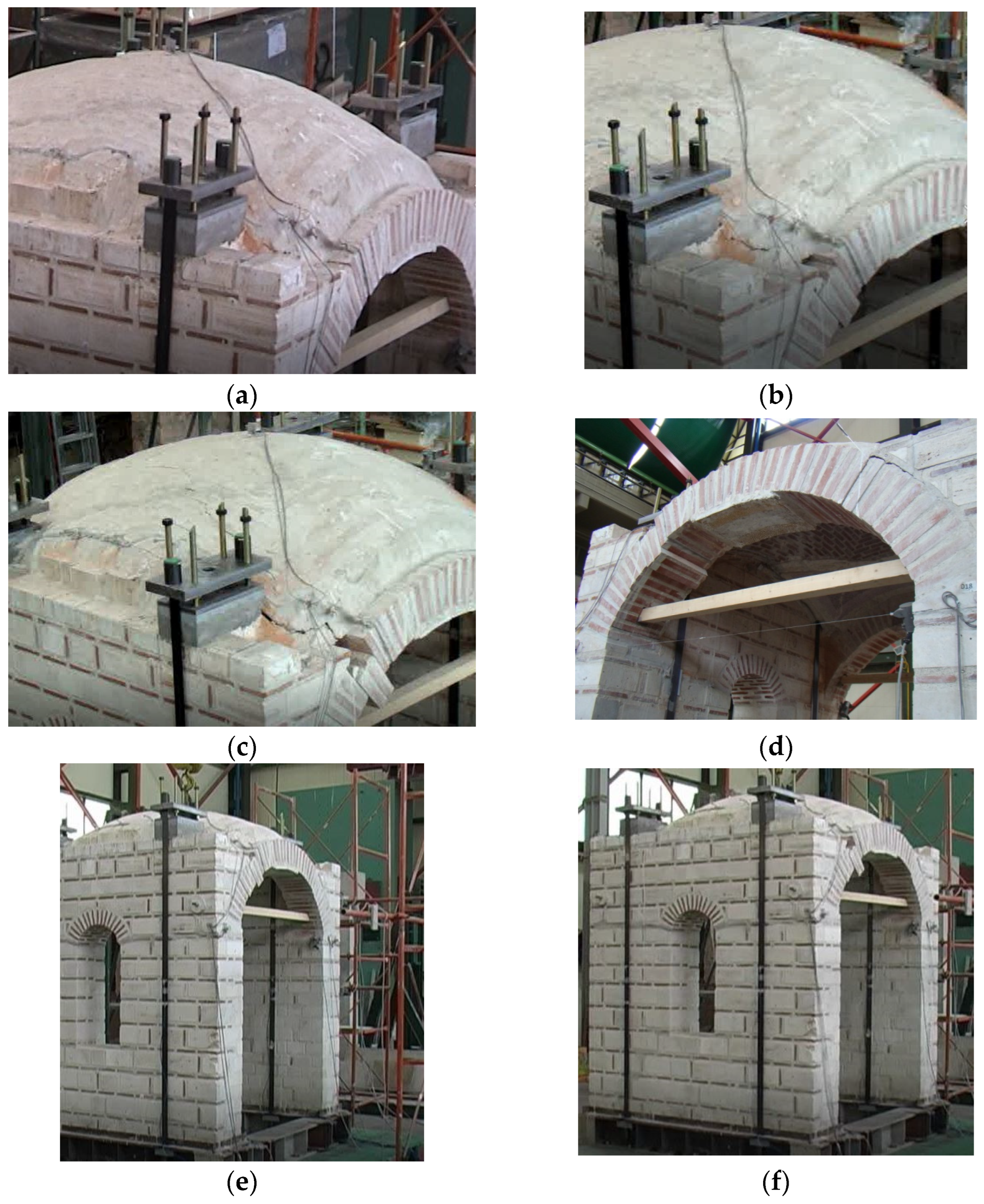
6.2. Observed Damage
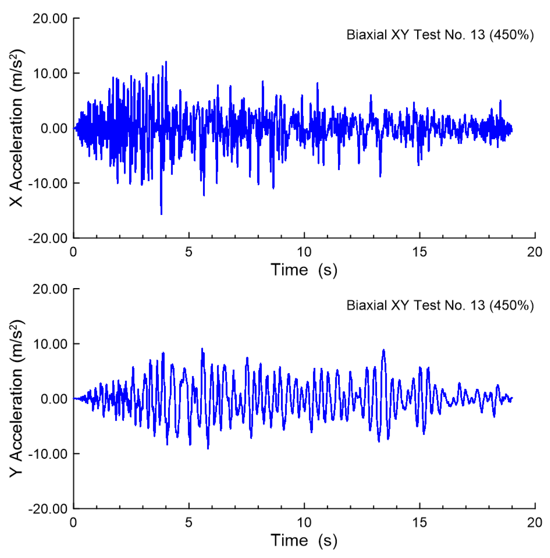
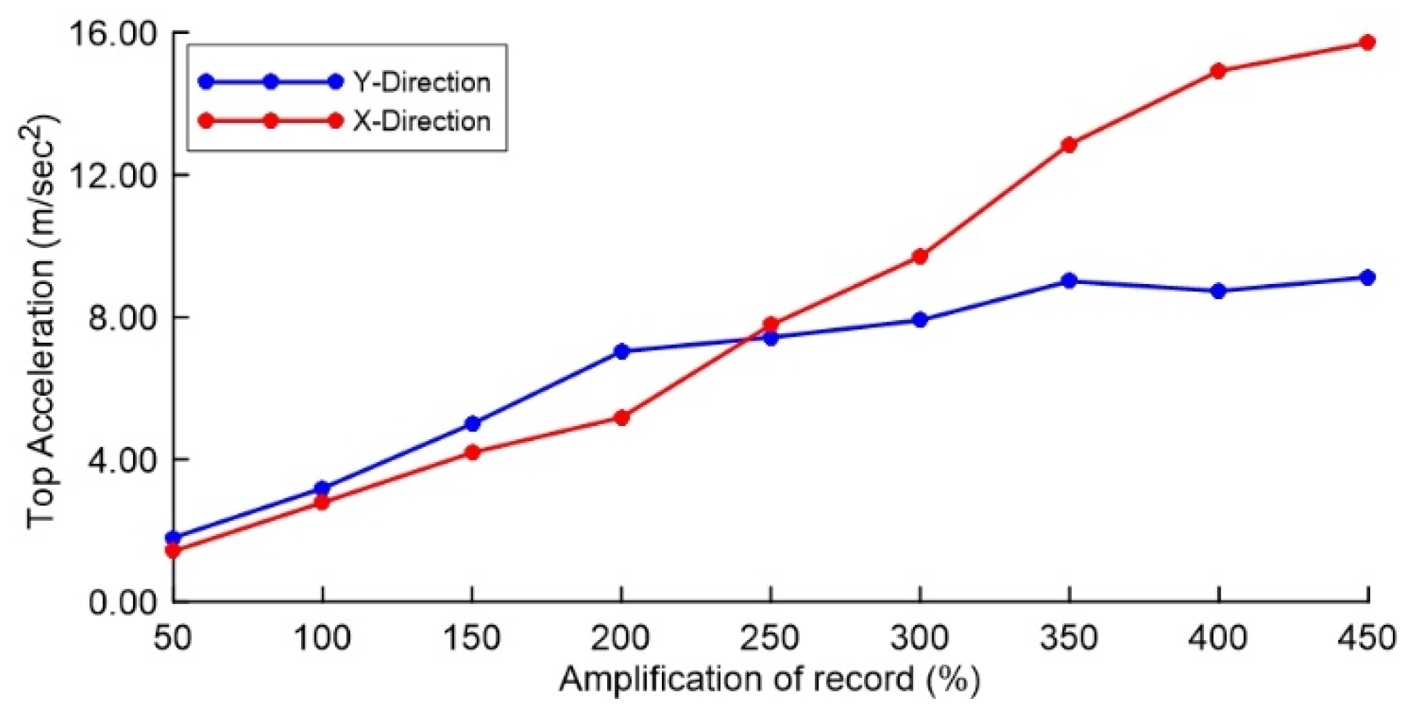
6.3. Accelerations Recorded at the Top of the Cross Vault
6.4. Out-of-Plane Displacements at the Top of the Piers
6.5. Loss of Prestressing during Testing
7. Discussion
Author Contributions
Funding
Institutional Review Board Statement
Informed Consent Statement
Data Availability Statement
Acknowledgments
Conflicts of Interest
References
- Miltiadou-Fezans, A.; Vintzileou, E.; Delinikolas, N.; Zaroyianni, E.; Chorafa, E. Pathology of the Dafni Monastery: Survey, monitoring of cracks, interpretationand numerical verification. In Proceedings of the 4th International Conference on Structural Analysis of Historical Constructions, Padova, Italy, 10–13 November 2004; pp. 1285–1294. [Google Scholar]
- Miltiadou-Fezans, A. A multidisciplinary approach for the structural Restoration of the Katholikon of Daphni Monastery in Attica Greece. Keynote Paper. In Proceedings of the 6th International Conference on Structural Analysis of Historical Constructions, Bath, UK, 2–4 July 2008; pp. 71–87. [Google Scholar]
- Mouzakis, C.; Adami, C.-E.; Karapitta, L.; Vintzileou, E. Seismic behaviour of a rehabilitated cross-vault. In Proceedings of the 8th International Conference on Structural Analysis of Historical Constructions, Wroclaw, Poland, 15–17 October 2012. [Google Scholar]
- Bertolesi, E.; Adam, J.M.; Rinaudo, P.; Calderon, P.A. Research and practice on masonry cross vaults-A review. Eng. Struct. 2019, 180, 67–88. [Google Scholar] [CrossRef]
- Bianchini, N.; Mendes, N.; Calderini, C.; Candeias, P.X.; Rossi, M.; Lourenco, P. Seismic response of a small-scale masonry groin vault: Experimental investigation by performing quasi-static and shake table tests. Bull. Earthq. Eng. 2022, 20, 1739–1765. [Google Scholar] [CrossRef]
- De Matteis, G.; Mazzolani, F.M. The Fossanova church: Seismic vulnerability assessment by numeric and physical testing. Int. J. Archit. Herit. 2010, 4, 222–245. [Google Scholar] [CrossRef]
- Rossi, M.; Calderini, C.; Lagomarsino, S. Experimental testing of the seismic in-plane displacement capacity of masonry cross vaults through a scale model. Bull. Earthq. Eng. 2016, 14, 261–281. [Google Scholar] [CrossRef]
- Milani, G.; Rossi, M.; Calderini, C.; Lagomarsino, S. Tilting plane tests on a small-scale masonry cross vault: Experimental results and numerical simulations through a heterogeneous approach. Eng. Struct. 2016, 123, 300–312. [Google Scholar] [CrossRef]
- Foti, D.; Vacca, V.; Facchini, I. DEM modeling and experimental analysis of the static behavior of a dryjoints masonry cross vaults. Constr. Build. Mater. 2018, 170, 111–120. [Google Scholar] [CrossRef]
- Shapiro, E.E. Collapse mechanisms of small-scale unreinforced masonry vaults. Master Thesis, Massachusetts Institute of Technology, Cambridge, MA, USA, 2012. Available online: http://hdl.handle.net/1721.1/72648 (accessed on 31 October 2022).
- Rossi, M.; Barentin, C.C.; Van Mele, T.; Block, P. Experimental study on the behaviour of masonry pavilion vaults on spreading supports. Structures 2017, 11, 110–120. [Google Scholar] [CrossRef]
- Williams, M.S.; Alejandra, A.; Victoria, L.; Yip, F. Model scale shaking table tests on masonry barrel and cross vaults. In Proceedings of the 15th World Conference on Earthquake Engineering, Lisbon, Portugal, 24–28 September 2012. [Google Scholar]
- Mark, R.; Abel, J.F.; O’Neill, K. Photoelastic and finite-element analysis of a quadripartite vault. Exp. Mech. 1973, 13, 322–329. [Google Scholar] [CrossRef]
- Rossi, M.; Calderini, C.; Roselli, I.; Mongelli, M.; De Gerardo, C.; Lagomarsino, S. Seismic analysis of a masonry cross vault through shaking table tests: The case study of the dey mosque in Algiers. Earthq. Struct. 2020, 18, 57–72. [Google Scholar] [CrossRef]
- Fagone, M.; Rotunno, T.; Bati, S.B. The groin vaults of St. John Hospital in Jerusalem: An experimental analysis on a scale model. Int. J. Archit. Herit. 2016, 10, 903–918. [Google Scholar] [CrossRef]
- Vintzileou, E.; Miltiadou-Fezans, A. Mechanical properties of three-leaf stone masonry grouted with ternary or hydraulic lime-based grouts. Eng. Struct. 2008, 30, 2265–2276. [Google Scholar] [CrossRef]
- Palieraki, V.; Vintzileou, E.; Miltiadou-Fezans, A.; Delinikolas, N. The use of radar techniques and boroscopy in investigating old masonry: The case of Dafni Monastery. Int. J. Archit. Herit. 2008, 2, 155–186. [Google Scholar] [CrossRef]
- Carydis, P.; Mouzakis, C.; Karapitta, L. Investigation of mechanical behavior of byzantine type of masonry with or without mosaics and evaluation of various intervention techniques-Phase I. Technical Report LEE/NTUA. (In Greek)
- Carydis, P.; Mouzakis, C.; Karapitta, L. Investigation of mechanical behavior of byzantine type of masonry with or without mosaics and evaluation of various intervention techniques-Phase II. Technical Report LEE/NTUA. (In Greek)
- Miltiadou-Fezans, A.; Kalagri, A.; Kakkinou, S.; Ziagou, A.; Delinikolas, N.; Zarogianni, E.; Chorafa, E. Methodology for in situ application of hydraulic grouts on historic masonry structures. The case of the Katholikon of Dafni Monastery. In In Proceedings of the 6th International Conference on Structural Analysis of Historical Constructions, Bath, UK, 2–4 July 2008; pp. 1025–1033. [Google Scholar]
- Carydis, P.; Mouzakis, C.; Karapitta, L. Investigation of mechanical behavior of byzantine type of masonry with or without mosaics and evaluation of various intervention techniques-Phase III. Technical Report LEE/NTUA. (In Greek)
- Badogiannis, E.; Miltiadou-Fezans, A.; Ipsilanti, E.; Dedeloudis, C.; Vintzileou, E.; Kalagri, A. Mix design and performance evaluation of grouts with superfine natural pozzolan. In Proceedings of the 8th International Conference on Structural Analysis of Historical Constructions, Wroclaw, Poland, 15–17 October 2012. [Google Scholar]
- Vintzileou, E.; Mouzakis, C.; Adami, C.-E.; Karapitta, L. Seismic behavior of three-leaf stone masonry buildings before and after interventions: Shaking table tests on a two-storey masonry model. Bull. Earthq. Eng. 2015, 13, 3107–3133. [Google Scholar] [CrossRef]
- Miltiadou-Fezans, A.; Vintzileou, E.; Mouzakis, C.; Dourakopoulos, J.; Giannopoulos, P.; Delinikolas, N. Structural analyses of the Katholikon of Daphni Monastery with alternative interventions improving its overall behaviour. In Proceedings of the 16th European Conference on Earthquake Engineering, Thessaloniki, Greece, 18–21 June 2018. [Google Scholar]


| Test Name | Excitation | Direction of Excitation | Amplification of Original Record (%) |
|---|---|---|---|
| 1BS | White noise | X | - |
| 2BS | White noise | Y | - |
| 3BS | White noise | Z | - |
| 4BS-17BS | Irpinia | X | Gradually increasing from 30 to 500 |
| 18BS | Irpinia | XY | 50 |
| 19BS | Irpinia | XY | 100 |
| 20BS | Irpinia | XY | 150 |
| 1AS | Sine sweep | X | - |
| 2AS | Sine sweep | Y | - |
| 3AS | Sine sweep | X | - |
| 4AS | Sine sweep | Y | - |
| 5AS | Irpinia | XY | 50 |
| 6AS | Irpinia | XY | 100 |
| 7AS | Irpinia | XY | 150 |
| 8AS | Irpinia | XY | 200 |
| 9AS | Irpinia | XY | 250 |
| 10AS | Irpinia | XY | 300 |
| 11AS | Irpinia | XY | 350 |
| 12AS | Irpinia | XY | 400 |
| 13AS | Irpinia | XY | 450 |
| 14AS | Sine sweep | X | - |
| 15AS | Sine sweep | Y | - |
| Test Name | Direction | Frequency (Hz) | Damping Ratio (%) |
|---|---|---|---|
| 1BS | X | 12.30 | 1.00 |
| 2BS | Y | 5.96 | 2.00 |
| 1AS | X | 10.68 | 3.47 |
| 2AS | Y | 3.52 | 4.67 |
| 3AS | X | 13.15 | 3.45 |
| 4AS | Y | 4.98 | 4.80 |
| 14AS | X | 12.38 | 3.48 |
| 15AS | Y | 3.78 | 6.96 |
| Biaxial Test XY | Base Acceleration (m/s2) | Top Acceleration (m/s2) | ||
|---|---|---|---|---|
| X | Y | X | Y | |
| 20BS (150%) | 1.92 | 2.15 | 4.27 | 4.46 |
| 7AS (150%) | 1.89 | 2.52 | 4.20 | 5.00 |
| 13AS (450%) | 7.87 | 6.76 | 15.71 | 9.12 |
| Test Name | Maximum Out-of-Plane Displacement at the Top of the Piers (mm) |
|---|---|
| 20BS (150%) | 4.60 * |
| 9AS (150%) | 0.06/0.14 |
| 13AS (450%) | 0.18/0.34 |
| Test Name | Displacement (mm) |
|---|---|
| 20BS (150%) | 14.83/12.52 (19.51/16.47) |
| 7AS (150%) | 7.11/17.21 |
| 13AS (450%) | 34.63/39.63 |
Publisher’s Note: MDPI stays neutral with regard to jurisdictional claims in published maps and institutional affiliations. |
© 2022 by the authors. Licensee MDPI, Basel, Switzerland. This article is an open access article distributed under the terms and conditions of the Creative Commons Attribution (CC BY) license (https://creativecommons.org/licenses/by/4.0/).
Share and Cite
Vintzileou, E.; Mouzakis, C.; Karapitta, L.; Miltiadou-Fezans, A. Shake-Table Testing of a Cross Vault. Buildings 2022, 12, 1984. https://doi.org/10.3390/buildings12111984
Vintzileou E, Mouzakis C, Karapitta L, Miltiadou-Fezans A. Shake-Table Testing of a Cross Vault. Buildings. 2022; 12(11):1984. https://doi.org/10.3390/buildings12111984
Chicago/Turabian StyleVintzileou, Elizabeth, Charalambos Mouzakis, Lucia Karapitta, and Androniki Miltiadou-Fezans. 2022. "Shake-Table Testing of a Cross Vault" Buildings 12, no. 11: 1984. https://doi.org/10.3390/buildings12111984