Article

Variable Factors Affecting Progressive Destruction of Composite Steel Tall Building

1
Civil Engineering Department, MISR Higher Institute for Engineering and Technology, Mansoura 7651012, Dakahlia Governorate, Egypt
2
Department of Structural Engineering, Faculty of Engineering, Mansoura University, Mansoura 35516, Dakahlia Governorate, Egypt
*
Author to whom correspondence should be addressed.
Buildings 2022, 12(10), 1704; https://doi.org/10.3390/buildings12101704
Submission received: 26 September 2022 / Revised: 11 October 2022 / Accepted: 13 October 2022 / Published: 16 October 2022

Abstract

:
In recent years, the presence of progressive collapse in tall buildings induced a catastrophic event which attracted the majority of the community’s attention. The purpose of this paper is to develop a 3D numerical analysis of tall building under column loss. A composite steel frame building with 25 stories with five spans in both directions is proposed. The building has 3 m story height and 8 m span in both directions. The building is designed through the commercial software SAP2000 software against wind loads based on Eurocode 1-2005. The focus here is to investigate various parametric studies under abrupt column loss of multi-story composite building. The effect of composite slab is considered with full composite action between beam and slab. The findings of a parametric formulation incorporating important parameters for the progressive collapse design technique are given and confirmed using nonlinear dynamic time history analyses. The assessment of results has been introduced based on deformation, axial force in columns, equivalent plastic strain, major moment and axial force in the considered beams above the column loss. Next, a probabilistic analysis has been performed to assess the behavior of composite steel buildings against column loss. The study investigates the critical column loss and pinpoints the location of the next critical column. The results show that the concrete grade, position of the removed column, beams cross-section, and place of bracings have a significant effect in the response of the building rather than the steel grade and bottom reinforcement density. The removal of exterior column has the significant increase of the axial force percentage by 111.4% for the corner column. The corner column removal gives the maximum equivalent plastic strain with a value of 0.00449. Furthermore, the results reveal the potential impact of uncertainty on the structural elements of the considered buildings through the progressive collapse analysis. The vertical displacement above the column is fitted with mean value of 0.0251387 m and with a coefficient of variation 0.01664.

1. Introduction

Progressive collapse has received a lot of attention in recent years after the catastrophic events affiliate the partial collapse of Ronan Point [1], the Murrah Federal Building [2] and the total collapse of the World Trade Center [3]. Progressive collapse is described as the failure of a main vertical element of a structure, which may lead to the failure of adjoining elements and, as a result, the partial or whole collapse of the building occurs [4]. This phenomenon has been produced by additional abnormal loads which are not considered in the design process. These loads are categorized as pressure or impact loads (gas explosions, blast, wind, environmental, aircraft impact, hazardous materials, earthquakes, and fire). Three conditions must be realized in the propagation of progressive collapse: the local failure of an element, the spreading of failure to the other elements, and the final collapse disproportionate to the initial failure. The first studies to reduce progressive collapse were stated in the 1970s by [5]. They suggested three concepts to reduce the risk of progressive collapse: event control, direct design and indirect design. Event control is achieved by eliminating the event, protecting against the event, and reducing the effect of the event. This concept from a structural point of view cannot be controlled so the structural design is an urgent need. Direct design methods integrate implicit control using an alternate path method which permits local failure to allocate or specific local resistance which provides strength to resist failure. Indirect design methods integrate implicit control through the provision of minimum strength, ductility, and continuity. The guidelines for the direct design methods are published by the General Services Administration and the Department of Défense. The indirect design methods are used in the general building codes and standards [6,7].
Many researchers have investigated the behavior of buildings against column loss. They conducted both numerical analyses and field tests in their studies. Izzuddin et al. [8,9] pointed out a simplified framework for the assessment of the collapse of multi-story buildings under column loss. This framework includes nonlinear and dynamic effects and ductility considerations. They concluded that the span size, the joint details at beam ends, and the additional slab reinforcements had a noticeable effect on progressive collapse. Next, Izzuddin [10] listed developments in the performance-based design of multi-story buildings in the view of progressive collapse. He addressed that the load factor approaches in the new design codes had shortcomings therefore, it was unsafe to estimate the dynamic response. The results also showed the merits of connection ductility and reinforcement, axial restraints, infill panels and rate sensitivity.
Lanhui Guo et al. [11] focused on the catenary action role in redistributing the internal load and mitigating the progressive collapse. Rigid composite joints have been tested experimentally and validated using finite elements. The results revealed high strength and good ductility. Hence, the composite joint showed great influence in the catenary action. Song et al. [12] performed a field test on a steel frame building by removing four columns in the perimeter of the first floor in order to simulate the progressive collapse and the load redistribution due to column loss. A numerical approach is also considered using finite element to validate the test results. The numerical analysis was suggested in 2D and 3D models. The dynamic amplification factor of 2 may lead to a conservative result. The strain results from 3D analysis were close to the results from the test experiments.
Kim et al. [13,14,15,16] investigated the effect of progressive collapse on several types of proposed structural systems: tubular structures, braced frames, moment resisting frames, tilted and twisted buildings and mega-frame structures. Kim [13] conducted a nonlinear static and dynamic analysis to evaluate the progressive collapse of tubular structures. The results revealed that the collapse happens when 11% of all members are removed from one building side. Corner columns in the diagrid system prevent the failure of corner diagrid elements. Next, Kim et al. [14] examined the potential of braced frame buildings with various types of bracing against progressive collapse. This study proved that inverted V-type braced frames showed superior ductile behavior. Braced buildings resist progressive collapse against column loss rather than moment resisting frames. Furthermore, Kim and Hong [15] evaluated the collapse capacities of tilted and twisted buildings. A comparison between regular, tilted and twisted buildings has been investigated. Finally, Kim and Jung [16] conducted a pushdown analysis of modular mega-frame structures based on column loss.
Kordbagh and Mohammadi [17] investigated the influence of seismicity level and the height of steel frames buildings under progressive collapse. The results confirmed that tall buildings and structures designed against greater seismic base shear are safe against progressive collapse. Naji and Ommetalab [18] studied the mitigation of progressive collapse of steel frames. A horizontal bracing system has been proposed on the perimeter of the topmost story. The results confirmed that horizontal bracing increases the resistance of moment frames against progressive collapse. Zhang et al. [19] studied the response of composite framed-structures under edge column loss experimentally and numerically. The effect of beam dimensions, slab thickness and diameter of the reinforcement were considered. Next, an analytical method has been proposed to predict collapse resistance. Tensile catenary actions have been developed at large deflections. Zhang et al. [19] revealed that the beam depth increase gave a greater plastic bearing capacity of the structure. Gade and Sahoo [20] examined the performance based plastic design method for special truss moment resisting frame against progressive collapse. The system with missing interior column revealed a better collapse resistance behavior and a better redistribution of seismic force demand over the height. Kim et al. [21] investigated the design parameters such as yield strengths of beam, columns, and braces, live load, elastic modulus, and damping ratio of steel buildings against progressive collapse. The beam yield strength was the effective design parameter in the moment resisting frame and the column yield strength was the effective design parameter in the dual system building.
Kiakojouri et al. [22] studied the progressive collapse of steel moment-resisting frames using pushdown simulations under column loss. Various parametric studies have been considered such as number of stories, material strain-rate effects, location of initial local failure, and column removal time. The results showed that the dynamic simulations induce displacements smaller than the ones predicted by static analysis. The progressive collapse capacity is directly proportional to column removal time [22]. Hadjioannou et al. [23] tested two large scale steel-concrete composite floor slabs under column loss. The used models were validated numerically with an accurate prediction of the structure’s response. Wang et al. [24] tested the capacity of typical steel-concrete composite frames under middle-edge column loss. The results showed the continuous steel deck and moment resisting connections increased the load and deformation capacities of the system and the yield line predicted the floor resistance at the flexural stage. Naji and Khodaverdi Zadeh [25] used the alternate path method to study the behavior of concentric and eccentric braced frames against progressive collapse. In the concentric braced frames, ductility increased with the decrease of bracing cross-sections. Fu [26,27] performed a numerical analysis on a suggested 20-story building using finite element under column loss. Fu [26,27] investigated the building behavior considering parametric studies for strength of materials, and upper reinforcement size. The results indicated that the beam to column connection at the column removal story should be designed to twice the load combination self-weight plus 0.25 of the occupant load and the upper reinforcement mesh sizes and the concrete grade has a slight effect on the response. Gao et al. [28] developed a concrete filled steel tube composite frame to examine the effect of progressive collapse. The findings demonstrated that when the bending stiffness of the beam is larger than the twofold value, it has a minor influence on the dynamic response of the model. The failure period has essentially small effect on the dynamic response of the model after 0.5 time of natural vibration period. Wang and Wang [29] Proposed a theoretical method to assess the progressive collapse resistance of composite steel frame building at the design stage. The accuracy of the method depends on boundary conditions and span-depth ratio. Zhang et al. [30] introduced an analytical solution for 2D bare and braced steel frame due to middle column removal. The beam to column stiffness, beam span, number of stories have a remarkable effect on the performance against collapse. Tian et al. [31] suggested a seismic progressive collapse resilient super-tall building and the design method. The proposed system can control response against column loss and earthquakes. Chen et al. [32] simulated the collapse of dry-joint masonry arched by finite-discrete element method. Selected geometric and physical parameters are also investigated. Peng et al. [33] evaluated newly designed composite modular buildings against column loss. The results indicated that the dynamic amplification factor was influenced by building height.
Despite the existing literature on progressive collapse under column loss, the randomness of the critical removed column position has received far too little attention. Furthermore, the majority of this literature only investigated the individual effect of various parameters (such as steel and concrete grades, the density of slab reinforcements, and the position of the vertical bracing on the façade) on the performance of selected structural elements due to progressive collapse.
This study addresses the existing shortcomings by proposing a progressive collapse analysis framework for a 25-story composite steel building that considers the effect of randomness in the parameters under consideration, particularly the uncertainty in the critical removed column position. In addition to the various parameters such as material strength, reinforcement densities, and vertical bracing position, the effect of slab densities and beam cross-section on progressive collapse analysis is considered. Furthermore, a probabilistic study is conducted to investigate the combined effect of these parameters on the response of structural elements under progressive collapse analysis.
This paper is organized as follows. The next section introduces the methodologies and subdivides into the material models of steel and reinforcement as bilinear hardening model and concrete as concrete damage plasticity model and validation for the simulation of composite action and column loss. The subsequent sections introduce the description of a proposed 25 multi-story composite steel building that has been analyzed using the commercial software ABAQUS software against column loss. Next, parametric studies have been conducted with variations of steel and concrete grades, density of top and bottom reinforcement of slabs, position of sudden abrupt column loss, beams cross- section, and locations of vertical bracing. Next, a probabilistic study with random design parameter have been also implemented to indicate the uncertainty for column loss. The paper finally ends with conclusions and recommendations for future work.

2. Methodology

2.1. Material Models

2.1.1. Material Model of Steel and Reinforcement

Nonlinear behavior is considered in the analysis. The material steel and reinforcement are modelled using elastic-linear hardening model. The model allows favorable effect of strain hardening on the design of structural metallic elements [34,35]. Four grades of steel S235, S275, S355, and S440 are used with mechanical properties as shown in Table 1 [36].

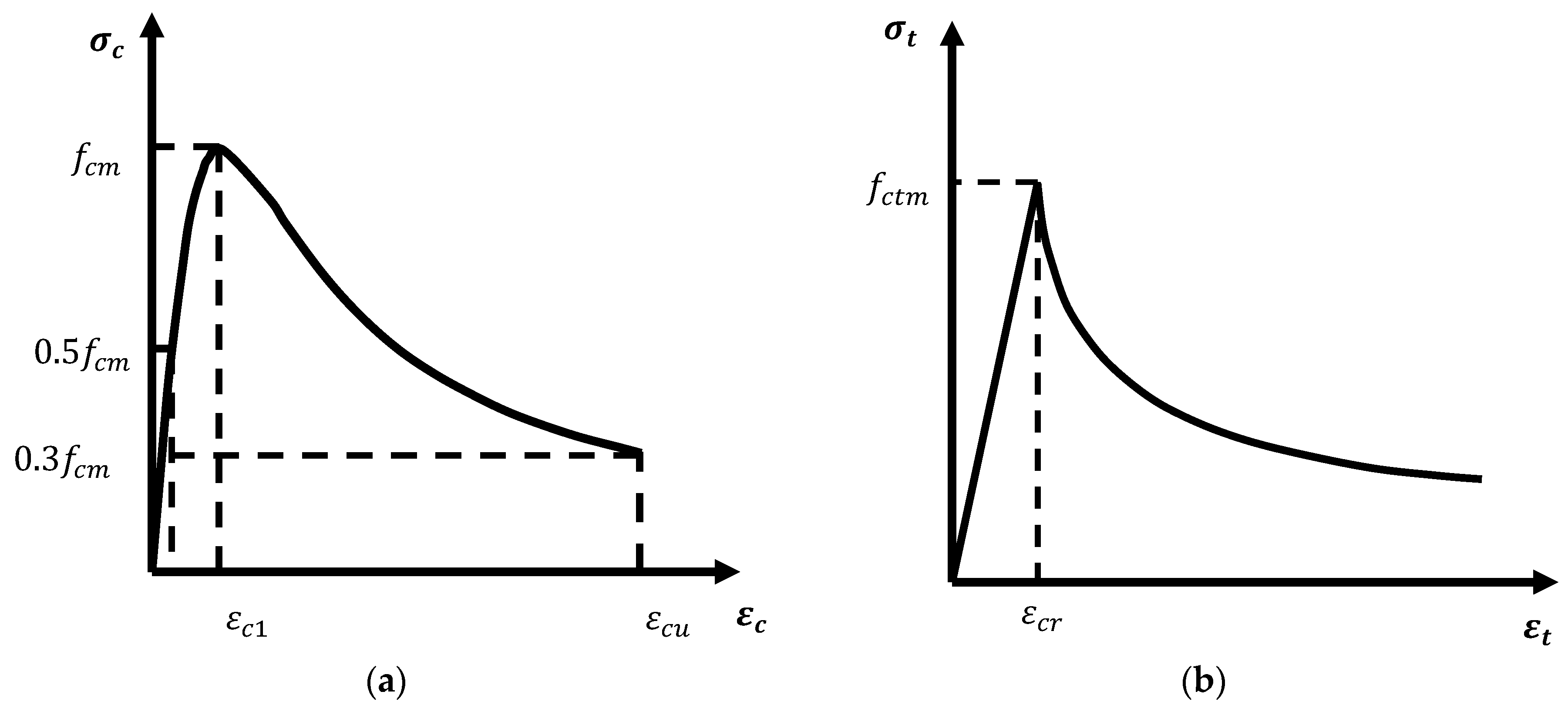
2.1.2. Material Model of Concrete

The concrete damage plasticity model CDPM is proposed to fulfill the nonlinear behavior including tension softening and strain hardening. The suggested model assumes the crushing of concrete in compression and cracking of concrete in tension. In this paper, Desayi and Krishnan [37] compression model for concrete is used by Equations (1)–(6). The tensile model in [38] is used to compute stress strain relationship and the ultimate tensile stress of concrete f c t m as displayed in Equation (5). Figure 1 shows the compressive and tensile stress-strain curve of the concrete.
ε c 1 = 0.0014 ( 2 e 0.024 f c m e 0.14 f c m )
ε c u = 0.004 0.0011 ( 1 e 0.0215 f c m )
E c = f c m ( 1 + ( ε c ε c 1 ) 2 ) / ε c
σ c = ε c E c / ( 1 + ( ε c ε c 1 ) 2 )
f c t m = 0.3 f c m 2 / 3
σ t = f c t m ( ε c r / ε t ) 0.4
where ε c 1 strain at peak stress; f c m average compressive strength of concrete; ε c u ultimate compressive strain for concrete; E c initial tangent stiffness modulus; ε c strain corresponding to compressive stress; σ c the compressive stress; f c t m ultimate tensile stress of concrete; ε t strain corresponding to tensile stress.
For the concrete damage model, a simple damage model by [39] is considered. The model equation under uniaxial tension or compression is:
d = 1 σ f
ε p = ε f E c
where f E c elastic strain at the peak stress; ε the total strain; ε p plastic strain with stiffness degradation; d the damage factor; σ the tension or compression stress; f is either the tensile or compressive strength of concrete as appropriate. The values of the concrete damage parameters are suggested based on [39,40,41,42,43]. The parameters are introduced in Table 2.

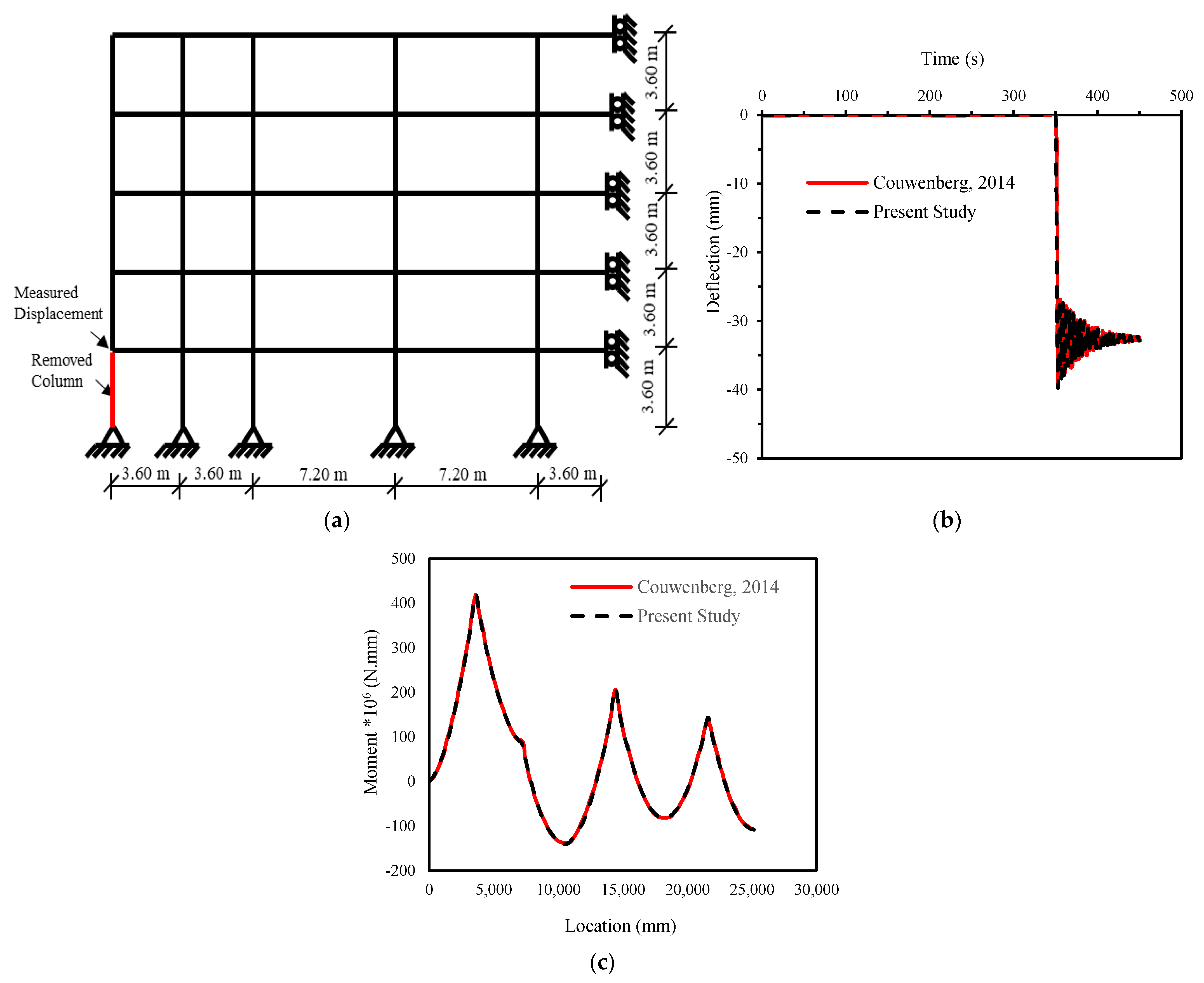
2.2. Validation of Numerical Models and the Composite Action

To validate the proposed numerical model’s capacity to describe the behavior of composite action between slabs and beams, a restrained I-beam with top slab of thickness 20.0 cm and width 2.0 m subjected to vertical concentrated load is provided. The I-beam has height of 1.20 m with web thickness 10.0cm, and flange width 1.0 m with thickness 10.0 cm. The model is developed in ABAQUS softwareto predict the composite response. A static general analysis is performed for fixed ends restrained simple beam with span of 20 m under a concentrated load of 100 kN applied at the middle of the beam. The vertical displacement at the mid span is computed by hand calculations including bending and shear deformations. The displacement value is 0.0010553 m. The displacement from Finite Element (FE) is 0.00106 m. A good agreement is achieved between the numerical model and hand calculation. Thus, the presented numerical model is accurate enough to simulate the composite behavior between slab and beam.
The beam is simulated using the Timoshenko *BEAM element (B31) in the ABAQUS software [34] element library. The slab is simulated using the four node *Shell element which has bending and membrane stiffness from the ABAQUS software [34] library. The beam element is modeled at the centerline of the beam and the shell element is modeled at the centerline of the slab. The interaction between the slab and beam is coupled using beam constraint equation *mpc to simulate the composite action.

2.3. Verification of Progressive Collapse
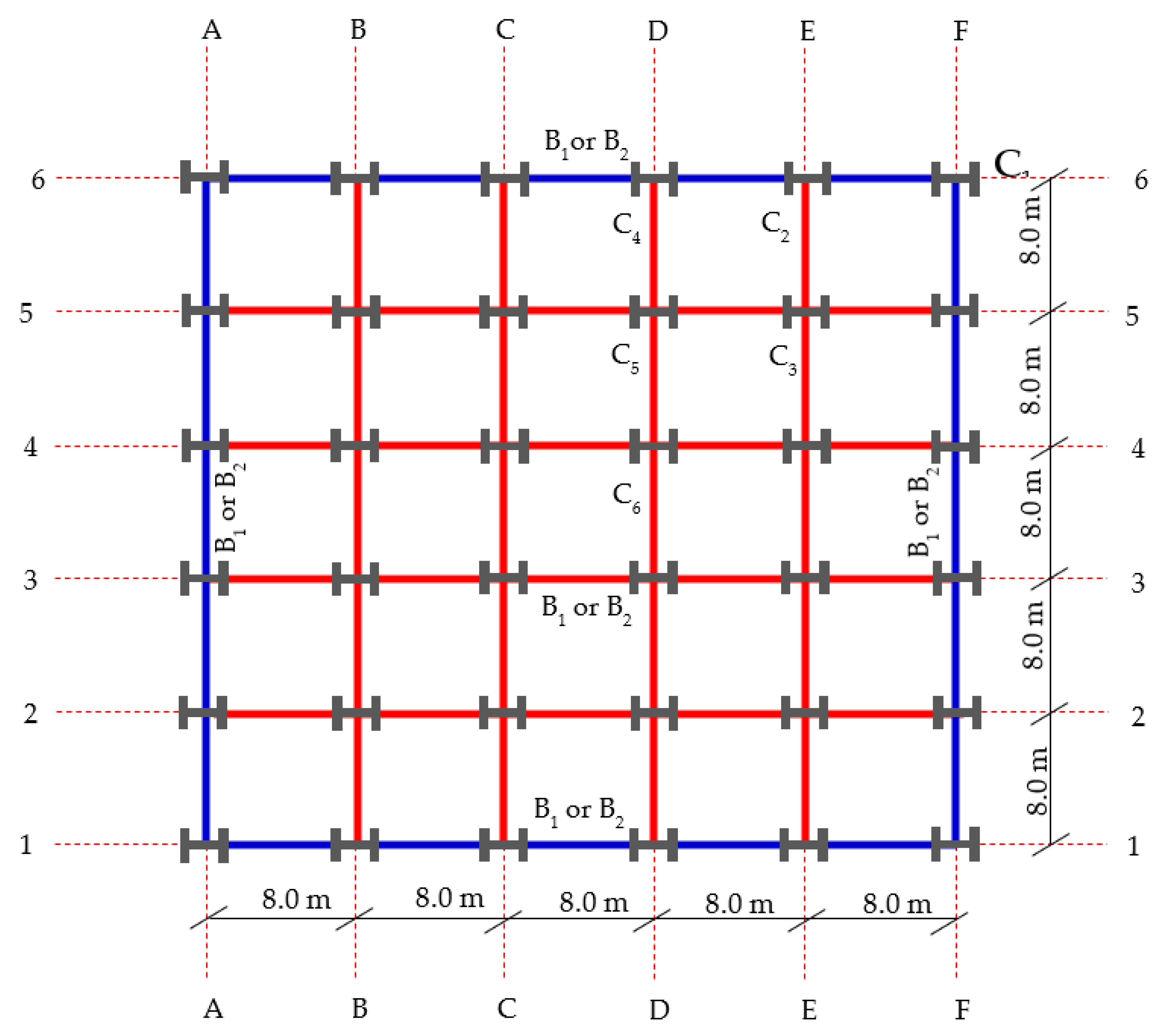
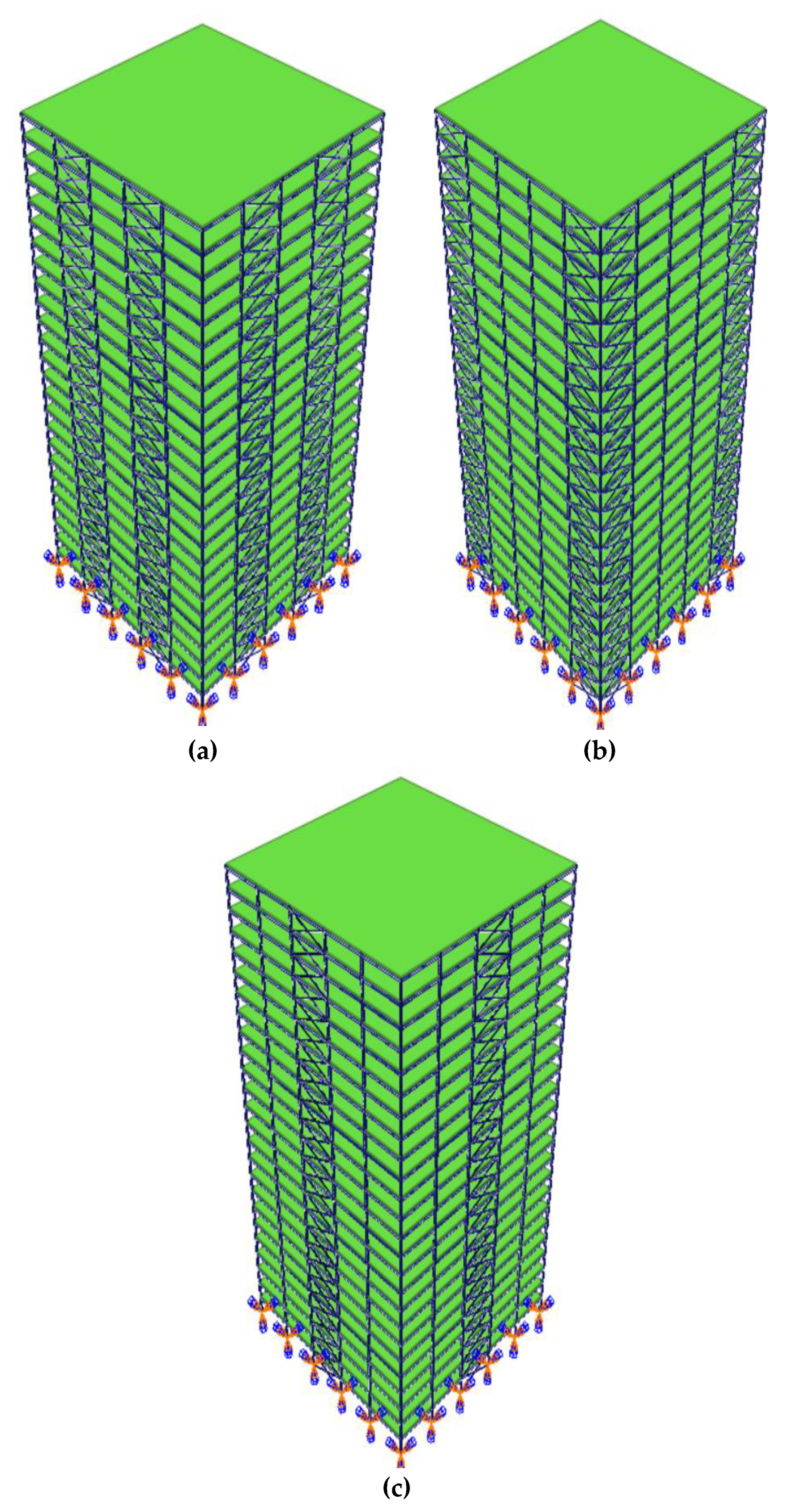
A five stories, 3.6-m reinforced concrete 2D frame that had previously been numerically verified by Couwenberg et al. [44] using ABAQUS software was used herein to validate the numerical model’s ability to simulate nonlinear dynamic time history under column loss. To reduce the analysis time of the FE model, only half of the frame was modeled. The rotation at the right ends of the beam were fixed. The beam column connections were assumed as pin connection. All dimensions of the frame are shown in Figure 2. The cross-section dimensions and reinforcements for the columns and beams are indicated in Table 3. All beams were subjected to uniform load 41.1 kN/m. The concrete was modeled using concrete damage plasticity model from ABAQUS software with grade C30/37. The reinforcements were modeled using an elastic-plastic material. Reinforcement grade was S500. The beam element is simulated using the Euler Bernoulli’s *BEAM element B23 which is suitable for the 2D frame analysis. The rebars in the beams and columns are represented as element property within the beam elements using *REBAR command. The frame view is shown in Figure 2. The load displacement relation at the node above the removed column was monitored. The maximum moment for the beam at the first floor was captured. The results show good agreement between the present study and Couwenberg et al. [44] as shown in Figure 2. Thus, the numerical model of the presented study is capable of capturing the behavior of the progressive collapse.

3. Case Study

Three Dimensions Modelling

A 25 stories composite steel frame building with five spans in both directions is created using ABAQUS software. The input file is generated using a python script by the authors. The analyses are conducted to evaluate the response against progressive collapse. The building has a 3 m story height and 8 m span in both directions. The building is designed through the commercial software SAP2000 software against wind loads based on Eurocode 1-2005 [45]. The building is located in a zone with mean wind speed 35 m/s, terrain category (II), structural factor = 1, Turbulence factor = 1, and orography factor = 1. The design approach in Eurocode 1-2005 [45] is used for all elements. The lateral sway is controlled to be around 11.05 cm. The considered loads are the self-weight and superimposed load of 150 kg/m2 and the occupant load of 250 kg/m2. The damping is assumed as 5% mass proportional damping. Nonlinear dynamic analysis is implemented. The main steps are (a) applying the gravity load in static step, then (b) removing the column over a period of 20 ms according to the requirements of GSA [46], keeping the gravity load constant, and using dynamic nonlinear analysis. It should be noted that according to the (GSA) [46], the displacements are calculated based on the load combination (SSL + 0.25OL). Where SSL is the self-weight, and superimposed load and OL is the occupant load applied to the structure. The lateral load is resisted by X-bracing. The slab thickness is 180 mm. The mesh size is studied and selected to be finer around the areas of interest to ensure that the response is accurately determined. The columns and beams cross-section dimensions are shown in Table 4. The elevation and the plan of the model structures are shown in Figure 3 and Figure 4, respectively.

4. Results and Discussions

A nonlinear dynamic analysis against progressive analysis using ABAQUS [34] software is performed for a 25 stories steel composite braced frame building under column loss. The recorded results are the vertical displacement above the removed column, axial force for the nearest corner, exterior and interior columns to the removed column, the maximum equivalent plastic strain, major moment and axial force for the beam above the column loss. Table A1, Table A2, Table A3, Table A4, Table A5, Table A6 and Table A7 in the Appendix A shows the parametric case studies which are proposed to evaluate the response of the building. The parametric studies are the steel and the concrete grades, the density of slab top and bottom reinforcements, position of the removed column, the outer and inner beams cross-section, and position of the vertical bracing on the façade.

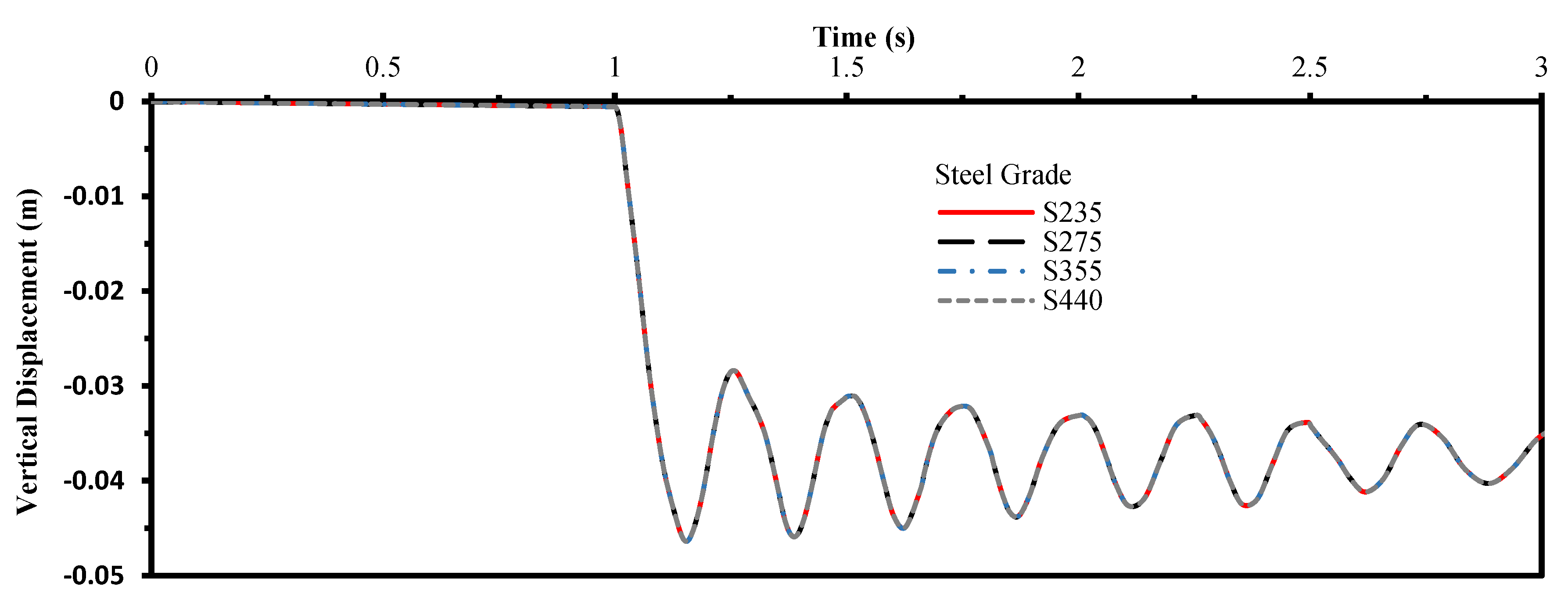
4.1. The Steel Grade for Columns and Beams

Four grades of steel are selected which are S235, S275, S355, and S440. The corner column C1 is removed from the first story. The vertical displacements are vibrated with a peak value of 46.40 mm for all steel grades. The percentage of increase in axial forces for the nearest corner, exterior, and interior columns to the removed column are 9.12%, 57.79%, and 13.056%, respectively, for all steel grades. The maximum equivalent plastic strain is rest at a maximum value of 0.00449. The peak moment and corresponding axial force for the beam above the removed column are almost 9.28 m.t and 35.5 ton. The results are almost identical for all steel grades. Figure 5 shows the history of vertical displacement above the removed column.

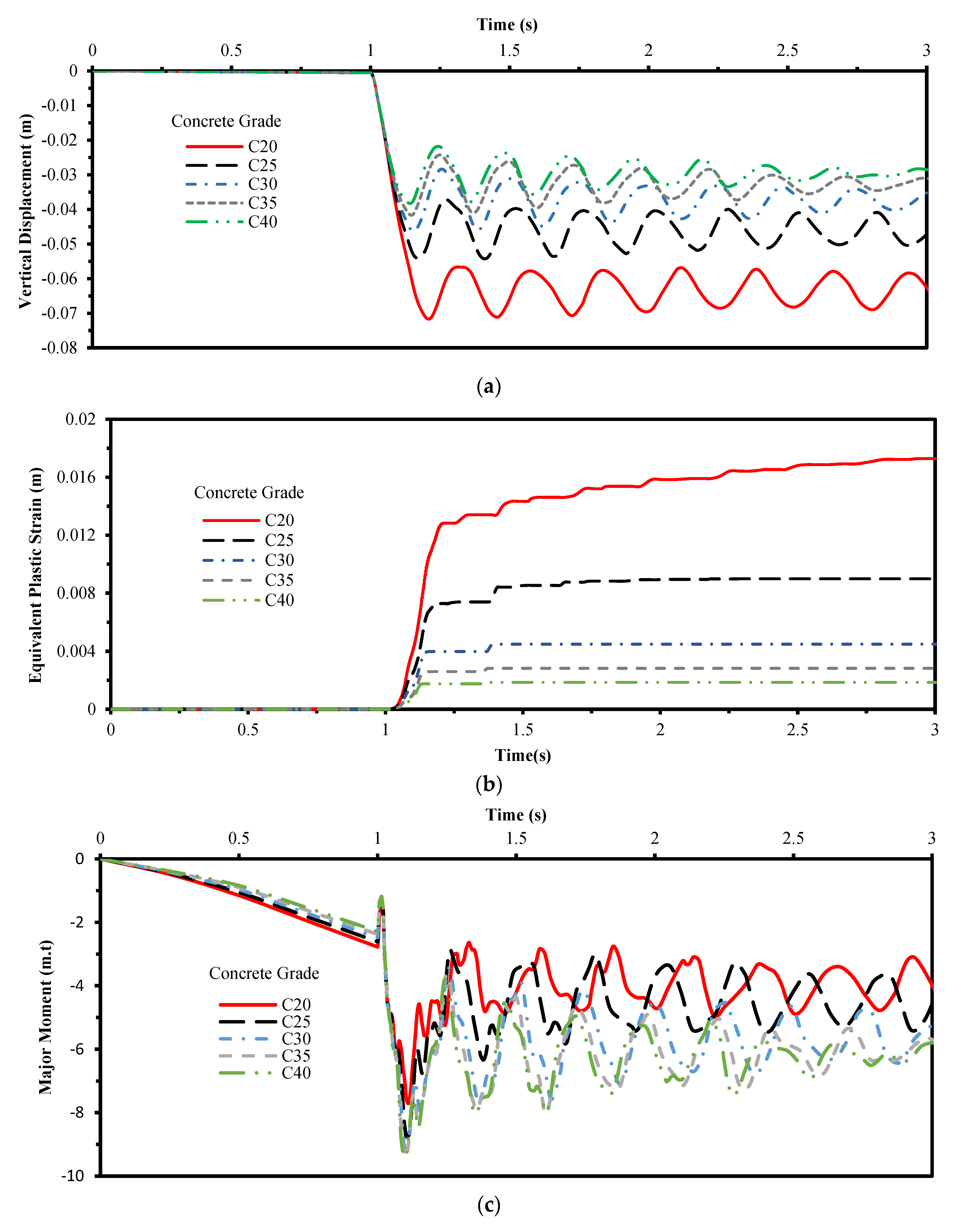
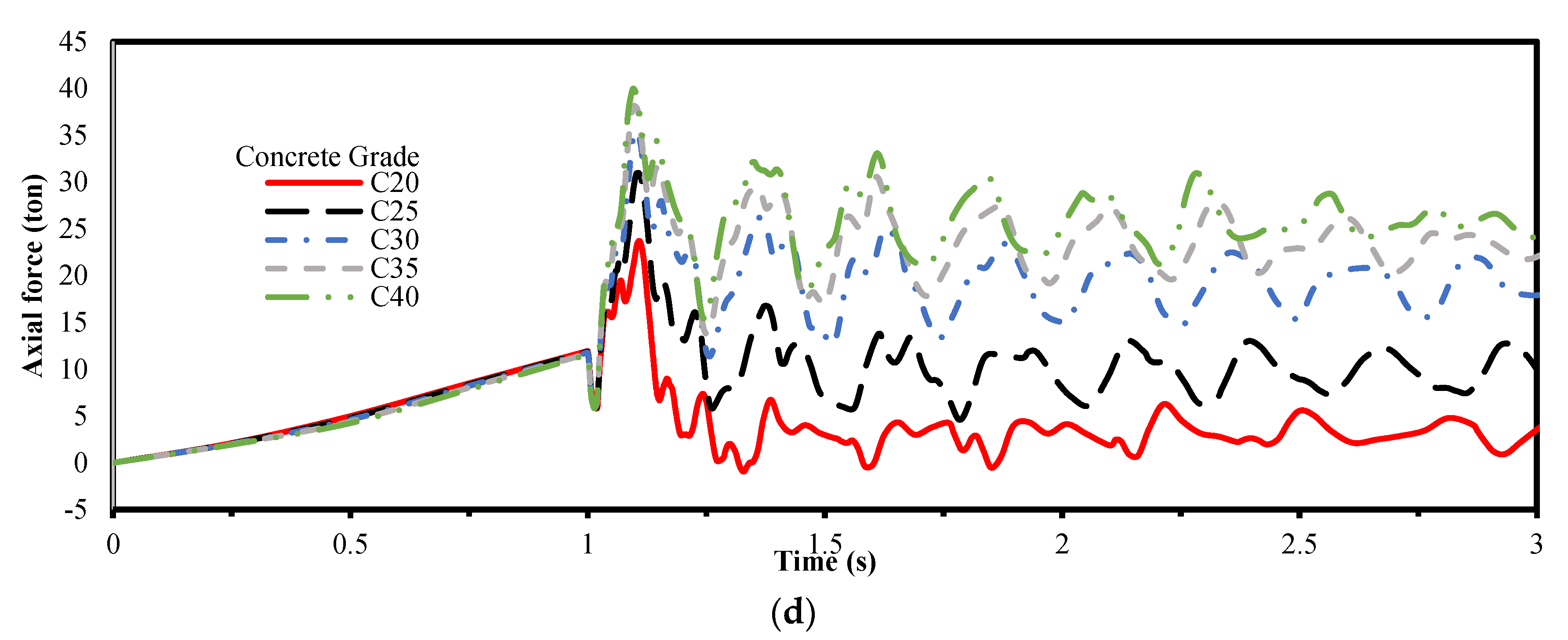
4.2. The Concrete Grade for Slab

Five grades of concrete are selected which are C20, C25, C30, C35, and C40. The various results due to the removal of column C1 shown in Figure 6. From these results, it can be observed that the vertical displacements are decreased with the increase of concrete strength grade. The maximum equivalent plastic strain has a range between 0.00185 and 0.0172793 for various grades. The peak value is decreased with the increase of concrete strength. The tying forces and major moment in beams are increased with the increase of concrete grade of slab. The excessive forces are redistributed through beam with the increase of the concrete strength. The increase in maximum normal force is between (5.6–10.5%), (57.06–59.8%) and (8.09–13.9%) for corner, exterior interior columns near to the removed column.

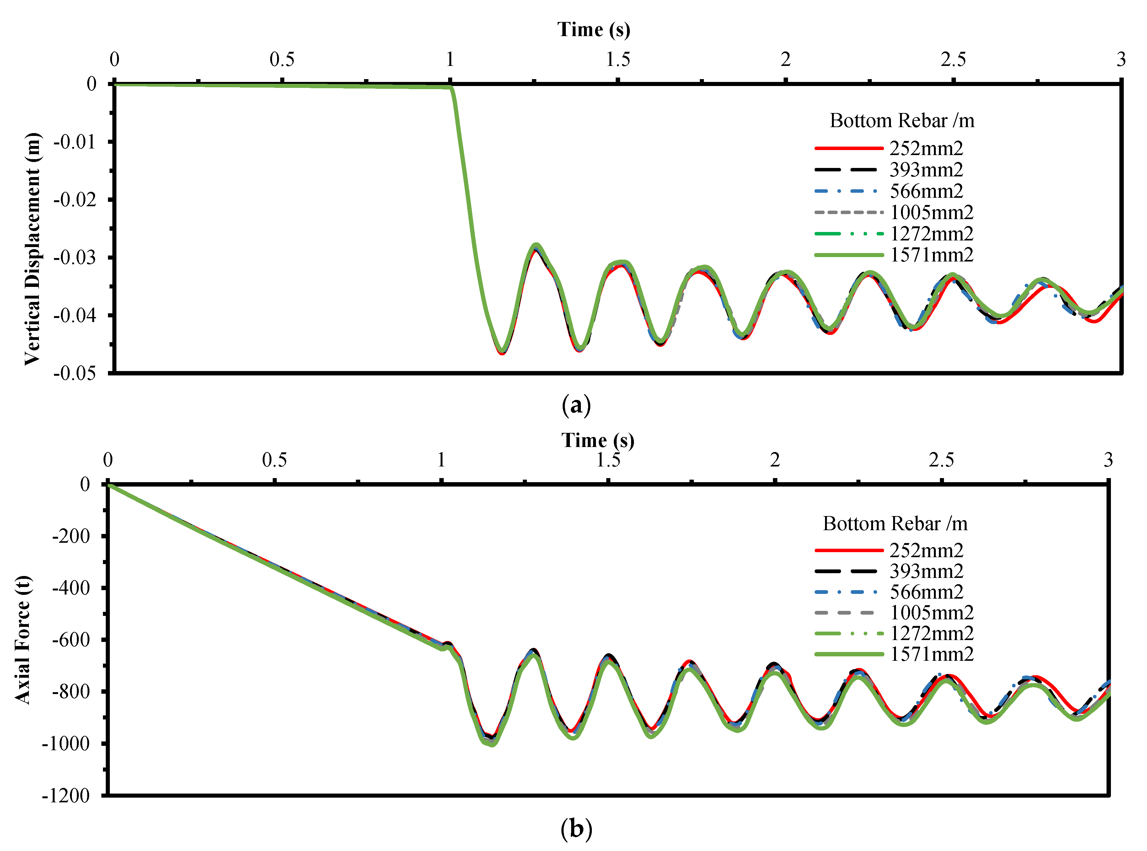
4.3. Bottom Reinforcement Density of Slab

The effect of bottom reinforcement density in slabs is investigated due to the removal of column C1. Six densities of reinforcement are selected which are 252 mm2/m, 393 mm2/m, 566 mm2/m, 1005 mm2/m, 1272 mm2/m, and 1571 mm2/m, respectively. The findings are shown in Figure 7. In addition, the maximum equivalent plastic strain is rested at 0.004484, the maximum major moment is almost 9.6 m.t, and the tying force is almost 36.3 ton for all density cases. The results show that for the density of reinforcement, the change of displacement, axial force in columns, equivalent plastic strain, major moment and axial force in beams are not significant.

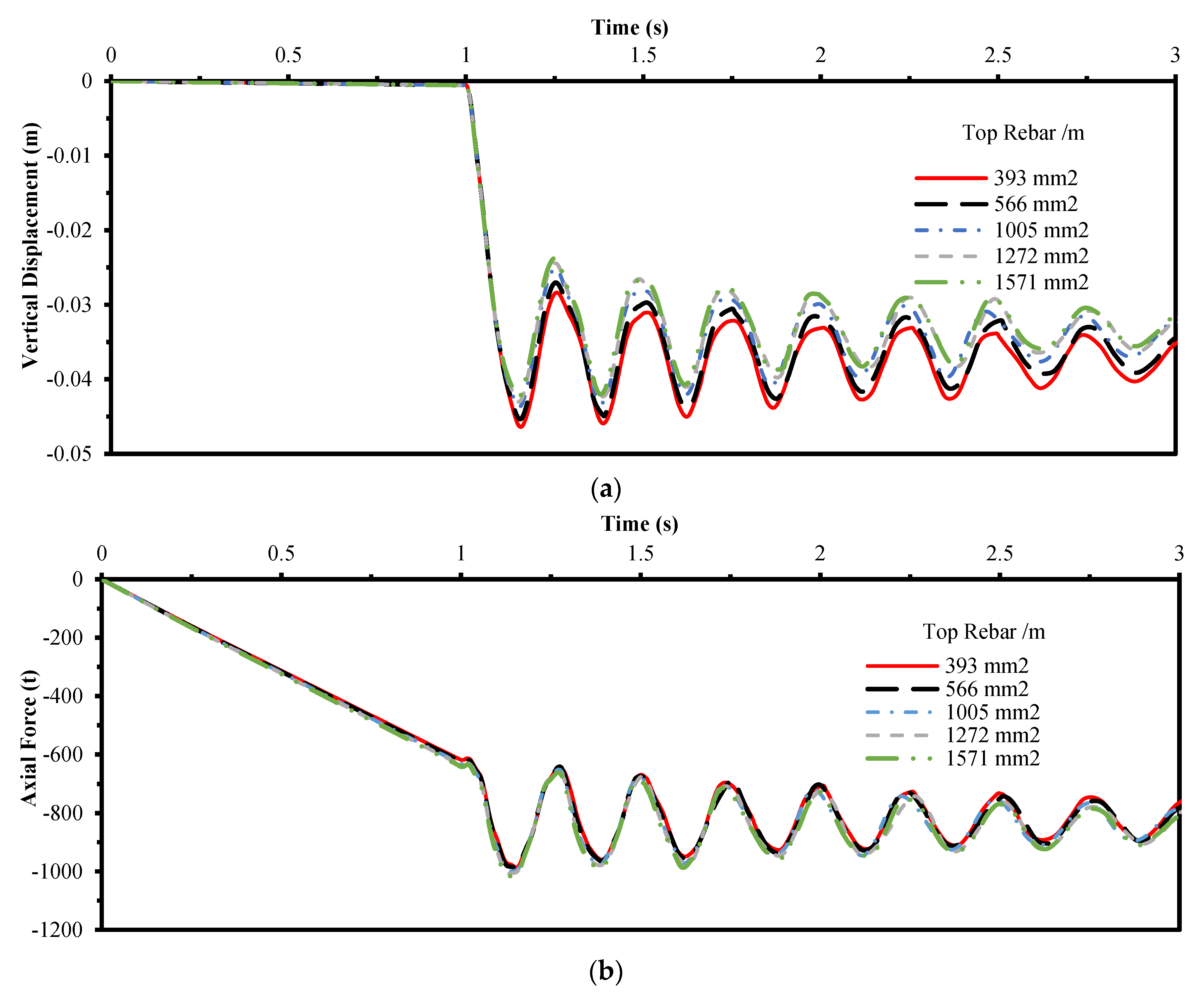
4.4. Top Reinforcement Density of Slab

The effect of top reinforcement density in slabs is investigated due to the removal of column C1. Five densities of reinforcement are selected which are 393 mm2/m, 566 mm2/m, 1005 mm2/m, 1272 mm2/m, and 1571mm2/m, respectively. The findings are shown in Figure 8. The maximum vertical displacements above the removed column for all cases are between (4.64 cm) and (4.24 cm). The maximum value for the equivalent plastic strain for all cases is between (0.0045) and (0.0039). The results revealed that the change of vertical displacement above the removed column, the equivalent plastic strain of slab, the axial force in the near exterior column, the major moment and the axial force in beam above the removed column are not obvious.

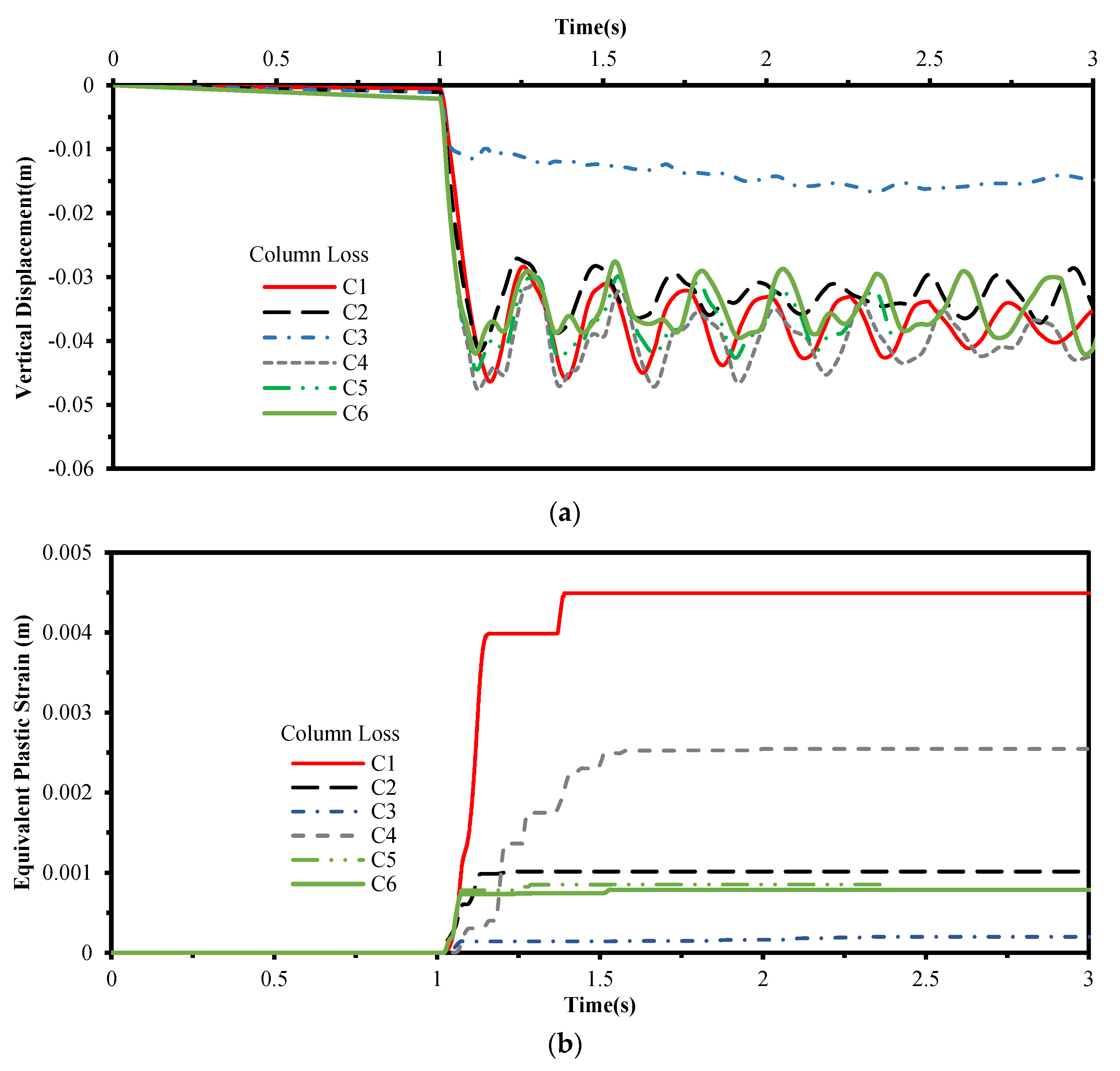
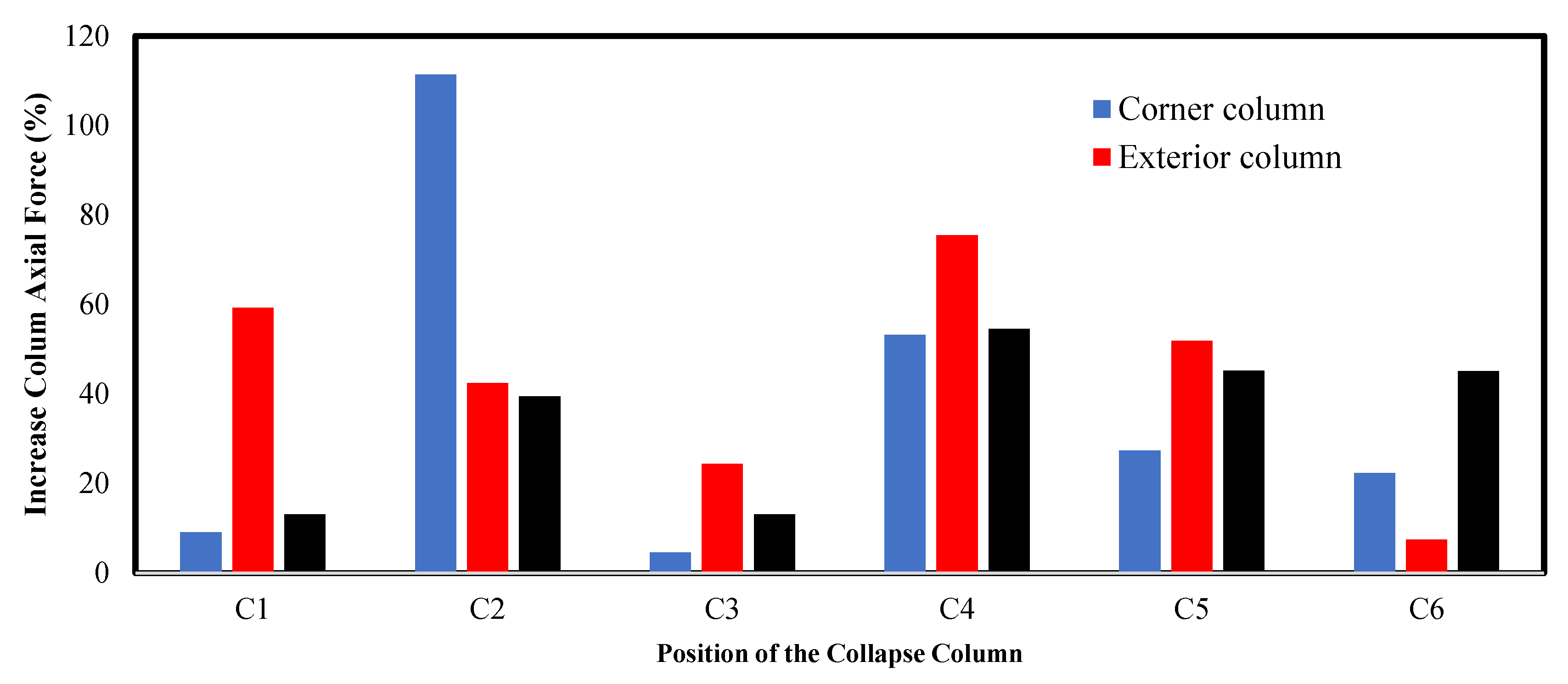
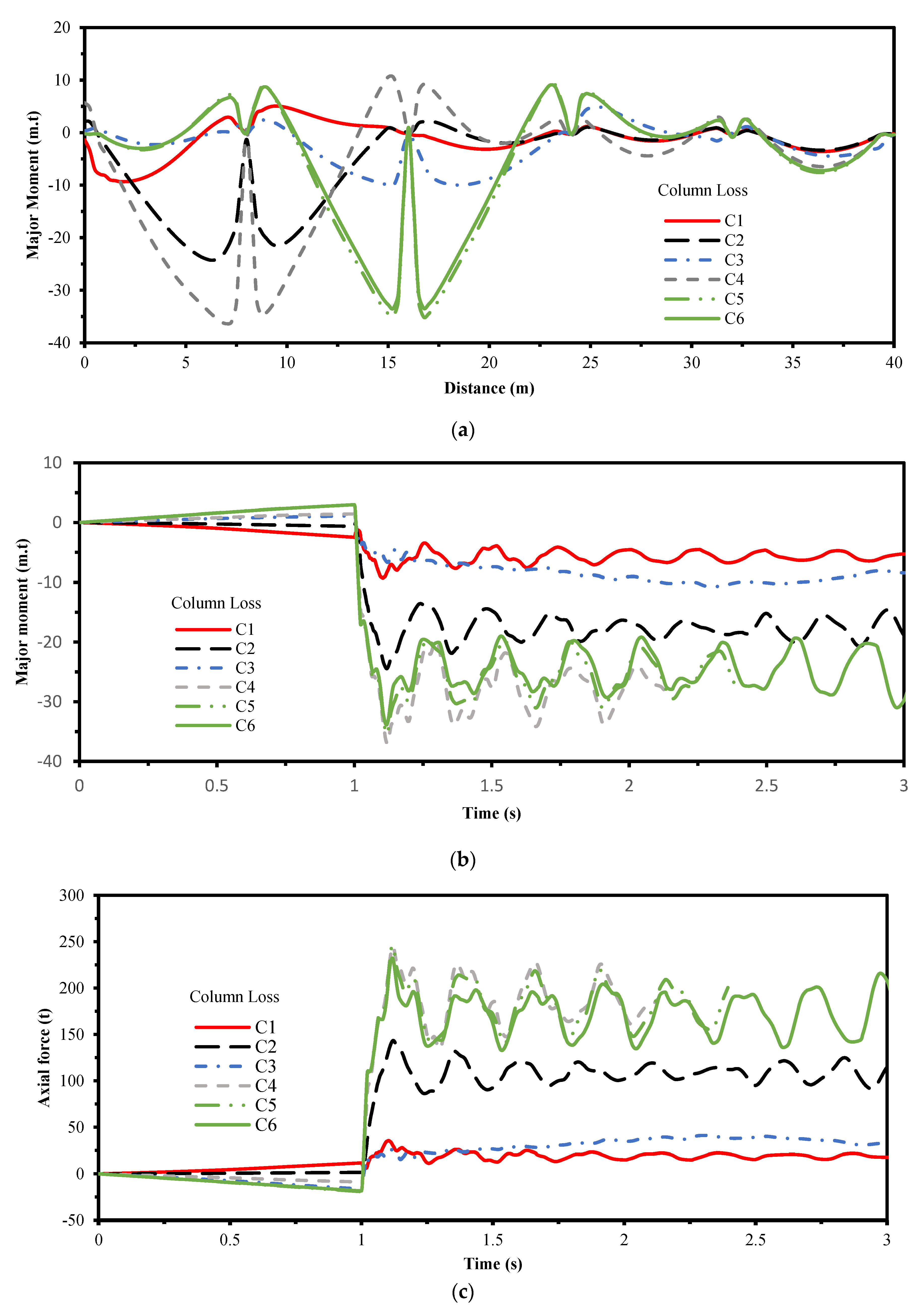
4.5. Position of the Column Loss

The position of the column loss has a significant effect on the response. Six cases are investigated on various places of columns in the first story. The cases for columns are C1, C2, C3, C4, C5, and C6 as shown in Figure 3. Figure 9, Figure 10 and Figure 11 show various results of the response. The analyses showed that the removal of C4 gives the maximum deflection with value of 4.70 cm. The removal of C3 gives no disturbance in the deflection due to the redistribution of the excessive loads by the vertical bracing. The critical case for the redistribution of vertical load is the removal of column C2. The increase of the axial force to the nearer corner column is 111.4%. The major moment and axial force for the beam above the removed column is critical for the case of the column loss C4 with value 37 m.t and 244.7 ton, respectively. The beam above the removal column has a crucial role in the redistribution of the excessive loads due to column loss, especially for the removal of interior columns. The removal of the corner column leads to excessive equivalent plastic strain in slabs with a value of 0.0045.

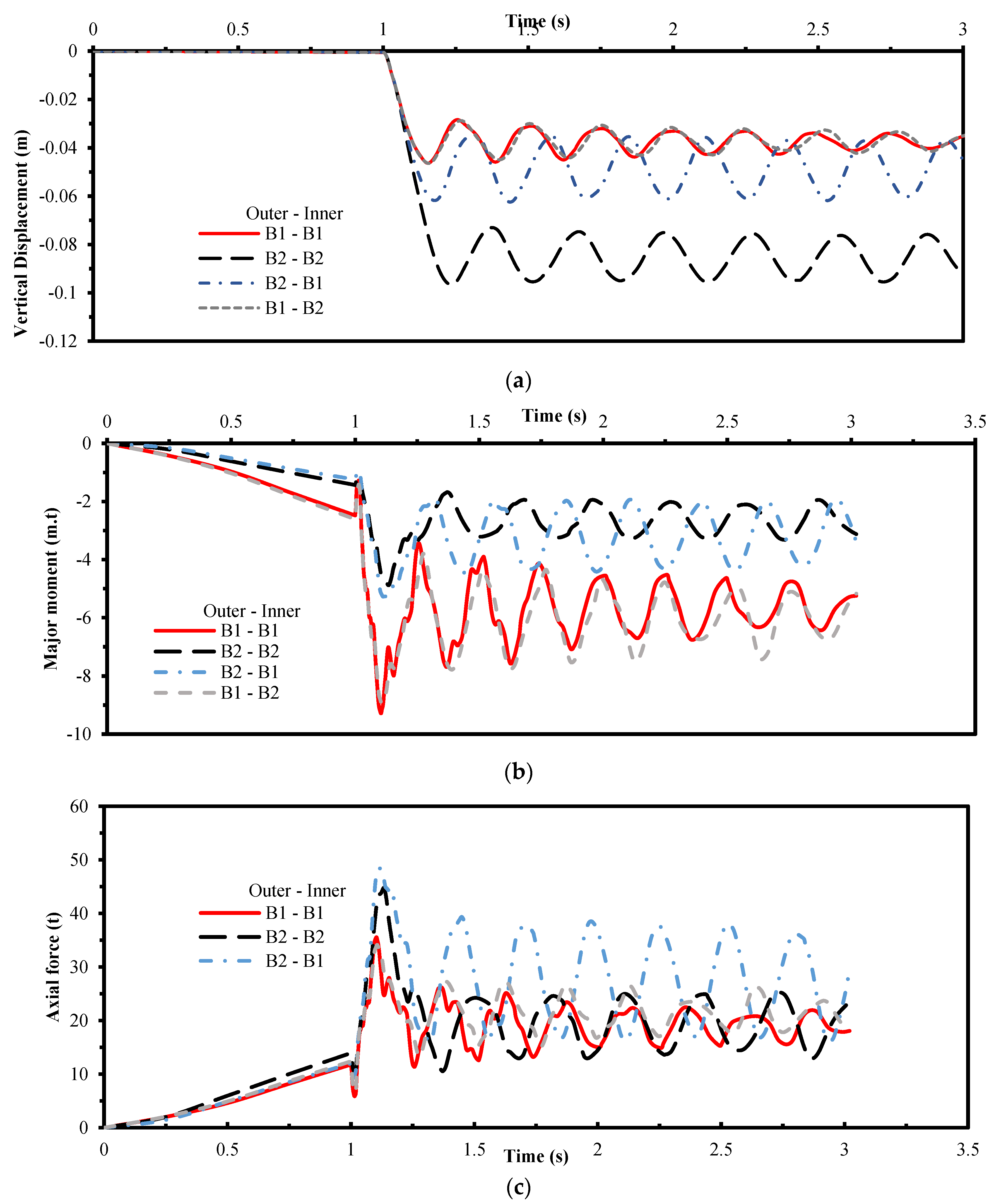
4.6. Beams Cross-Section

Four cases of analyses with two beams cross-section (B1 and B2) are investigated. The corner column C1 are removed from the first story. The study is conducted to examine the effect of beam on the distribution of excessive forces due to column loss. The results in Figure 12 show that, the decrease in cross-section of beams is accompanied by an increase in the vertical displacement and equivalent plastic strain. The beams with large cross-section attract much moment and axial forces as a result of the increase in the stiffness. The increase in major moment and axial force of beam is about 90% and 36%, respectively. The maximum change of axial force in columns is about 9% which are not significant. The beam cross-section decreases the displacement with maximum percentage about 108%.

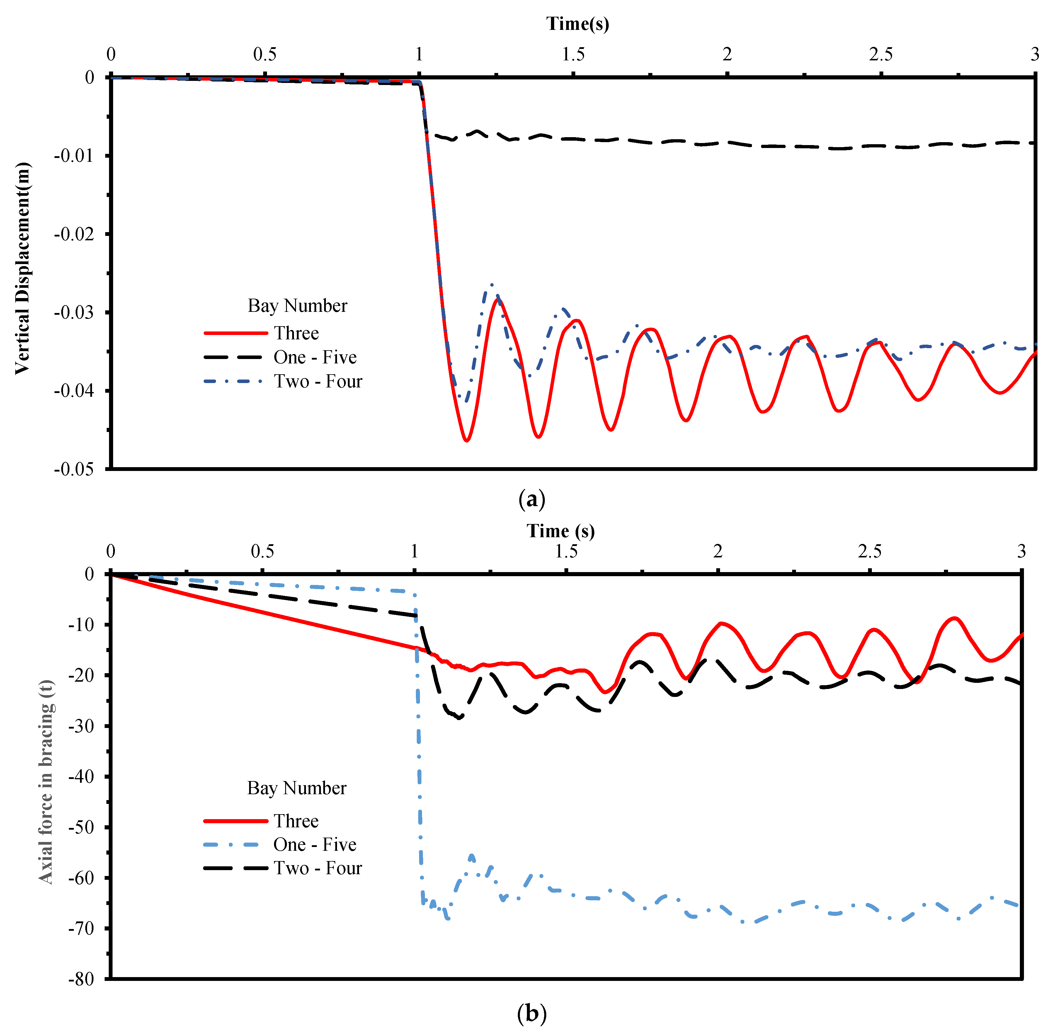
4.7. Bracing Locations

Three cases of bracing locations are studied due to the removal of corner column C1. The bracing locations are chosen as follow: bays one and five, bays two and four, and bay three. The results for displacement above the removed column and the normal force in bracing behind the removed column are shown in Figure 13. The bracing can resist the excessive force due to the removal of the column behind it. The displacement above the removed column does not vibrate if the bracing behind the removed column.

5. Uncertainty Treatment in Finite Element Modelling

While the preceding sections only explored the individual effect of the different parameters (such as the steel and the concrete grades, the density of slab top and bottom reinforcements, position of the removed column, the outer and inner beams cross-section, position of the vertical bracing on the façade) on the performance of selected structural elements due to the progressive collapse, this section considers the concurrent effect of these parameters. The exhaustive consideration of uncertainty stemming from material parameters and other sources (the position of the removed column) provide insights on balancing the computation complexity and model accuracy. Thereby, this exercise introduces a good balance between computational complication and accuracy of progressive collapse predictions. For instance, the preceding results show the marginally influence of the uncertainty associated with the concrete grade, beam cross-section, and position of the removed column on the vertical displacement above the removed column. The primary goal of this section is to suggest a systematic approach for consideration of uncertainty in the material modelling and other sources devoted to progressive collapse assessment. Developing such an approach requires careful selection of input variables, an appropriate experimental design strategy, finite element runs with the frame building parameters informed from the experimental design. The following section of this study briefly outlines each of these steps followed by application examples.

5.1. Input Parameter Selection and Experimental Design Strategy

Based on the findings of the preceding sections, the input parameters chosen for the model building includes: (a) steel grades [beam girders and rebar (fy)] and the concrete grades(fcm), (b) the density of slab top and bottom reinforcements, (c) position of the removed column, (d) outer and inner beams cross-section, and (e) position of the vertical bracing on the façade. These nine parameters are also shown in Table 5. Using the above parameter ranges, an experimental design is formulated. This study adopts the Latin Hypercube strategy belonging to the space-filling family of designs that is known to efficiently explore the parameter sample space. In fact, the general rule-of-thumb suggests that the number of runs equaling 10 times the number of parameter variables (nine in this case), that is 10 × 9 = 90 should be sufficient to capture parameter uncertainties. Due to the high computation runtime clocked on a 4.4 GHZ processor and 64.0 GB internal RAM, this study conducts a total of 20 design runs for the progressive collapse analysis considering uncertainty treatment as shown in Table 5.

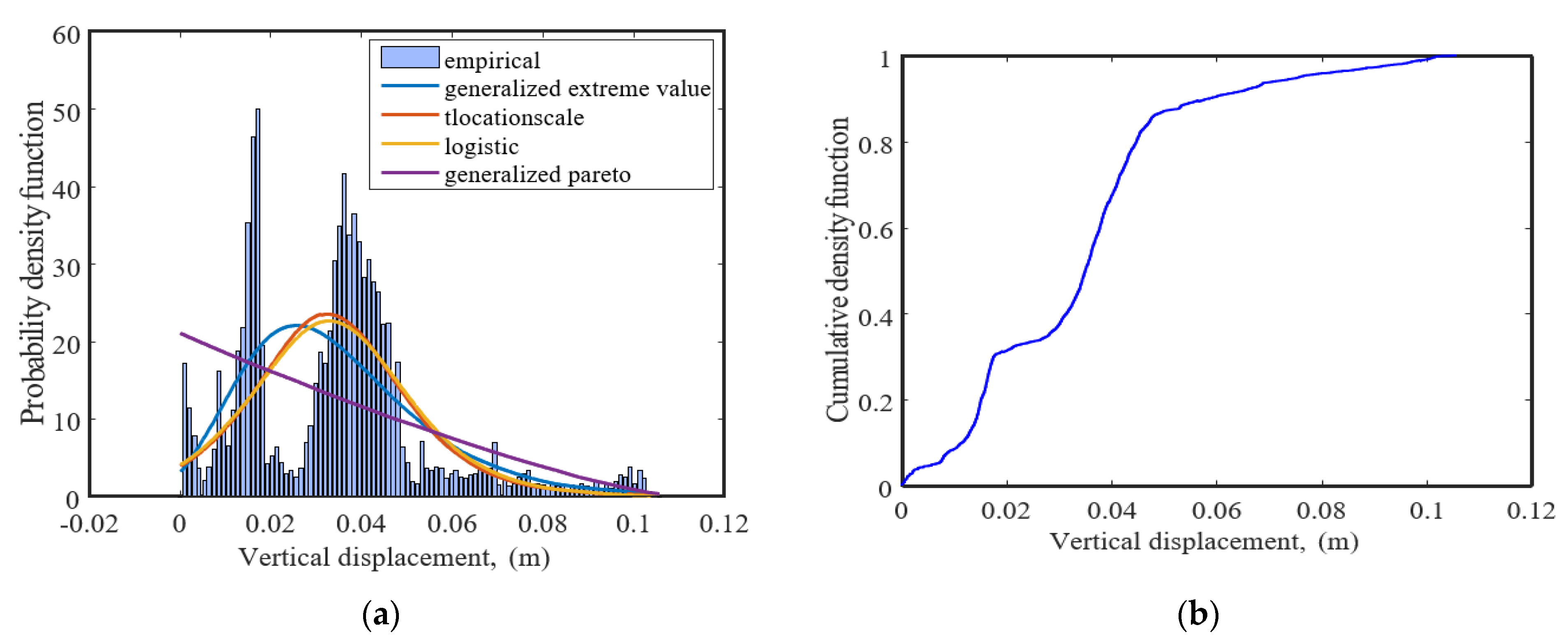
5.2. Probabilistic Progressive Collapse Analysis

Each row of the experimental design matrix developed in the previous steps helps inform a finite element frame building model. Following that, a progressive collapse analysis is carried out for each run. The results systematically high-lights the role of uncertainty on the structural response through progressive collapse analysis. For instance, the wide variation of the increased axial force due to the column collapse, as shown in the box-whisker plots in Figure 14. Additionally, this figure presents the five-number summary that describes the minimum and maximum values, upper and lower quartiles, and median of the considered response due to column collapse (the increased axial force). For corner and interior columns underlines the substantial influence of the uncertainty in the position of the removed column. Additionally, for the increased axial force due to the column collapse, it is observed the Generalized Extreme Value distribution is the best fit with a mean value of 0.0251387 mm and with a coefficient of variation of 0.01664 as shown in Figure 15a. Additionally, cumulative density function (CDF) of the time-dependent vertical displacement due to the column collapse considering the uncertainty approach is demonstrated in Figure 15b. The above findings highlight that ignoring the uncertainty, especially in the removed column position, and considering only mean estimates may lead to a potential over-or-under prediction of the structural element’s response through progressive collapse analysis.

6. Conclusions

This paper assesses the behavior of a 25 multi-story braced frame building under sudden abrupt column loss. Numerical FE models are developed with various parametric studies by considering the concrete, steel, and reinforcement strength, density of reinforcement, and position of the column loss, beams cross-section, and locations of the bracings. Next, this study proposes a framework for progressive collapse analysis that jointly considers the influence of column failures and uncertainty in material and deterioration parameters. Based on the parametric studies and the probabilistic analysis, the following conclusions are drawn:
  • The maximum plastic strain occurs in the slab for the case of corner column loss with a value of 0.00449.
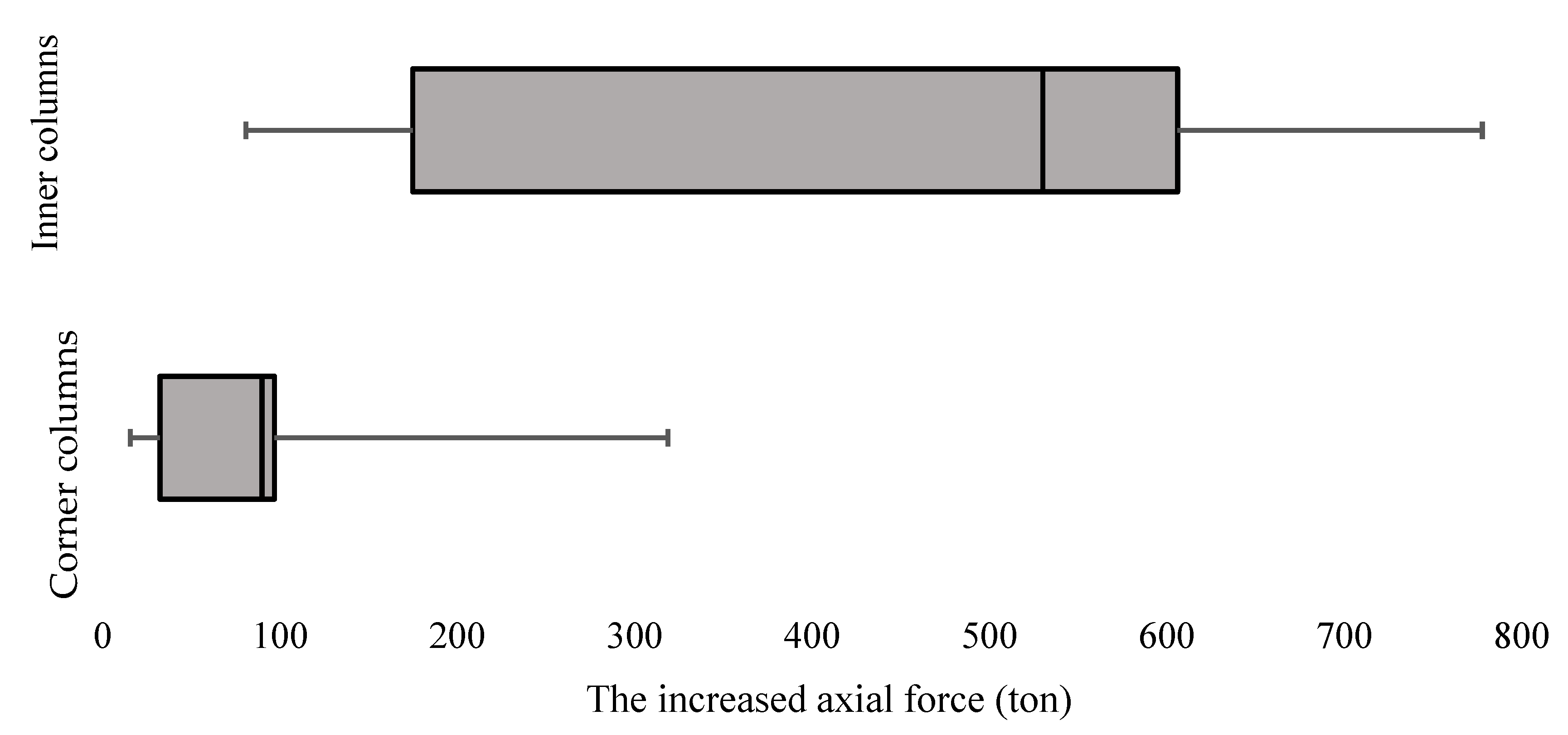
  • The sudden removal of the exterior column induces the maximum excessive percentage 111.4% of the axial force in the corner column.
  • The concrete strength of slabs has a crucial impact on the response rather than the steel strength of columns and beams.
  • The density of the bottom and upper reinforcement has no impact on the response rather than the upper reinforcement may affect the deflection with a minor value.
  • The removal of inner columns has a much significant effect on the beam major moment and tying forces
  • For corner column removal, the cross-section of outer beams has a significant role in the response and the redistribution of the excessive forces.
  • The present study recommends an exhaustive consideration of uncertainty for progressive collapse analysis, especially considering uncertainty in position of the removed column, the outer and inner beams cross-section, and position of the vertical bracing on the façade. For other parameters, such as the density of slab top and bottom reinforcements, consideration of mean parameters is sufficient.
  • Future avenues of research on this topic will include more discussions on probabilistic models and uncertainty and state the weight of each variable.

Author Contributions

S.L.: conceptualization, methodology, software, validation, writing—original draft preparation. M.M.: visualization, formal analysis, writing—review and editing. M.E.E.M.: supervision, project administration, writing—review and editing. All authors have read and agreed to the published version of the manuscript.

Funding

This research received no external funding.

Data Availability Statement

Data sharing is not applicable to this article.

Conflicts of Interest

The authors declare no conflict of interest.

Notations

EModulus of Elasticity σ c the compressive stress
fyYield stress of steel ε t strain corresponding to tensile stress
fuUltimate stress of steel ε the total strain
ε y Yield strain of steel ε p plastic strain with stiffness degradation
ε u l t Ultimate strain of steel d the damage factor
f c t m ultimate tensile stress of concrete σ the tension or compression stress
ε c 1 strain at peak stress f the tensile or compressive strength of concrete
f c m average compressive strength of concrete ψ The dilation angle
ε c u ultimate compressive strain for concrete γ Eccentricity
E c initial tangent stiffness modulus k Ratio of initial equivalent biaxial compressive yield stress to initial uniaxial compressive yield stress
ε c strain corresponding to compressive stress f b o / f c o Stress invariant ratio

Appendix A

Design Parameters for cases of column loss
Table A1. Effect of steel yield strength.
CaseSteel
(fy) MPa
Concrete
(fcm) MPa
Rebar
(fy) MPa
Bottom Rebar
mm2/m
Top rebar
mm2/m
Collapse ColumnBeamsBracing Location
OuterInner
123530235566393C1B1B1Bay 3
227530235566393C1B1B1Bay 3
335530235566393C1B1B1Bay 3
444030235566393C1B1B1Bay 3
Table A2. Effect of concrete strength.
CaseSteel
(fy) MPa
Concrete (fcm) MPaRebar
(fy) MPa
Bottom Rebar
mm2/m
Top Rebar
mm2/m
Collapse ColumnBeamsBracing Location
OuterInner
135520235566393C1B1B1Bay 3
235525235566393C1B1B1Bay 3
335530235566393C1B1B1Bay 3
435535235566393C1B1B1Bay 3
535540235566393C1B1B1Bay 3
Table A3. Bottom rebar density.
CaseSteel
(fy) MPa
Concrete (fcm) MPaRebar
(fy) MPa
Bottom Rebar
mm2/m
Top rebar
mm2/m
Collapse ColumnBeamsBracing Location
OuterInner
135530235252393C1B1B1Bay 3
235530235393393C1B1B1Bay 3
335530235566393C1B1B1Bay 3
4355302351005393C1B1B1Bay 3
5355302351272393C1B1B1Bay 3
6355302351571393C1B1B1Bay 3
Table A4. Top rebar density.
CaseSteel
(fy) MPa
Concrete (fcm) MPaRebar
(fy) MPa
Bottom Rebar
mm2/m
Top Rebar
mm2/m
Collapse ColumnBeamsBracing Location
OuterInner
135530235566393C1B1B1Bay 3
235530235566566C1B1B1Bay 3
3355302355661005C1B1B1Bay 3
4355302355661272C1B1B1Bay 3
5355302355661571C1B1B1Bay 3
Table A5. Position of the collapse column.
CaseSteel
(fy) MPa
Concrete (fcm) MPaRebar
(fy) MPa
Bottom Rebar
mm2/m
Top Rebar
mm2/m
Collapse ColumnBeamsBracing Location
OuterInner
135530235566393C1B1B1Bay 3
235530235566393C2B1B1Bay 3
335530235566393C3B1B1Bay 3
435530235566393C4B1B1Bay 3
535530235566393C5B1B1Bay 3
635530235566393C6B1B1Bay 3
Table A6. Inner and outer beams cross-section.
CaseSteel
(fy) MPa
Concrete (fcm) MPaRebar
(fy) MPa
Bottom Rebar
mm2/m
Top Rebar
mm2/m
Collapse ColumnBeamsBracing Location
OuterInner
135530235566393C1B1B1Bay 3
235530235566393C1B2B2Bay 3
335530235566393C1B2B1Bay 3
435530235566393C1B1B2Bay 3
Table A7. Bracing location.
CaseSteel
(fy) MPa
Concrete (fcm) MPaRebar
(fy) MPa
Bottom Rebar
mm2/m
Top Rebar
mm2/m
Collapse ColumnBeamsBracing Location
OuterInner
135530235566393C1B1B1Bay 3
235530235566393C1B1B1Bays 1, 5
335530235566393C1B1B1Bays 2, 4

References

  1. Pugsley, A.; Saunders, S.O. Report of the Inquiry into the Collapse of Flats at Ronan Point, Canning Town; HM Stationery Office: Richmond, UK, 1968.
  2. Federal Emergency Management Agency (FEMA). The Oklahoma City Bombing: Improving Building Performance through Multi-Hazard Mitigation; Federal Emergency Management Agency: Washington, DC, USA, 1996.
  3. NCSTAR; NIST. Final Report on the Collapse of the World Trade Center Towers; National Construction Safety Team for the Federal Building Fire Safety: Gaithersburg, MD, USA, 2005.
  4. Kiakojouri, F.; De Biagi, V.; Chiaia, B.; Sheidaii, M.R. Progressive collapse of framed building structures: Current knowledge and future prospects. Eng. Struct. 2020, 206, 110061. [Google Scholar] [CrossRef]
  5. Leyendecker, E.V.; Ellingwood, B.R. Design Methods for Reducing the Risk of Progressive Collapse in Building; U.S. Government Printing Office: Washington, DC, USA, 1977. [CrossRef] [Green Version]
  6. ACI 318-11; Building Code Requirements for Structural Concrete (ACI 318-11). American Concrete Institute: Farmington Hills, MI, USA, 2011.
  7. ASCE 7-10; Minimum Design Loads for Buildings and Other Structures. American Society for Civil Engineers: Reston, VA, USA, 2000.
  8. Izzuddin, B.; Vlassis, A.; Elghazouli, A.; Nethercot, D. Progressive collapse of multi-storey buildings due to sudden column loss—Part I: Simplified assessment framework. Eng. Struct. 2008, 30, 1308–1318. [Google Scholar] [CrossRef] [Green Version]
  9. Vlassis, A.; Izzuddin, B.; Elghazouli, A.; Nethercot, D. Progressive collapse of multi-storey buildings due to sudden column loss—Part II: Application. Eng. Struct. 2008, 30, 1424–1438. [Google Scholar] [CrossRef] [Green Version]
  10. Izzuddin, B. Mitigation of progressive collapse in multi-storey buildings. Adv. Struct. Eng. 2012, 15, 1505–1520. [Google Scholar] [CrossRef]
  11. Guo, L.; Gao, S.; Fu, F.; Wang, Y. Experimental study and numerical analysis of progressive collapse resistance of composite frames. J. Constr. Steel Res. 2013, 89, 236–251. [Google Scholar] [CrossRef]
  12. Song, B.I.; Giriunas, K.A.; Sezen, H. Progressive collapse testing and analysis of a steel frame building. J. Constr. Steel Res. 2014, 94, 76–83. [Google Scholar] [CrossRef]
  13. Kim, J.; Lee, Y.H. Progressive collapse resisting capacity of tube-type structures. Struct. Des. Tall Spec. Build. 2010, 19, 761–777. [Google Scholar] [CrossRef]
  14. Kim, J.; Lee, Y.; Choi, H. Progressive collapse resisting capacity of braced frames. Struct. Des. Tall Spec. Build. 2011, 20, 257–270. [Google Scholar] [CrossRef]
  15. Kim, J.; Hong, S. Progressive collapse performance of irregular buildings. Struct. Des. Tall Spec. Build. 2011, 20, 721–734. [Google Scholar] [CrossRef]
  16. Kim, J.; Jung, M. Progressive collapse-resisting capacity of modular mega-frame buildings. Struct. Des. Tall Spec. Build. 2013, 22, 471–484. [Google Scholar] [CrossRef]
  17. Kordbagh, B.; Mohammadi, M. Influence of seismicity level and height of the building on progressive collapse resistance of steel frames. Struct. Des. Tall Spec. Build. 2017, 26, e1305. [Google Scholar] [CrossRef]
  18. Naji, A.; Ommetalab, M.R. Horizontal bracing to enhance progressive collapse resistance of steel moment frames. Struct. Des. Tall Spec. Build. 2019, 28, e1563. [Google Scholar] [CrossRef]
  19. Zhang, J.-Z.; Li, G.-Q.; Jiang, J. Collapse of steel-concrete composite frame under edge-column loss—Experiment and its analysis. Eng. Struct. 2020, 209, 109951. [Google Scholar] [CrossRef]
  20. Gade, V.P.; Sahoo, D.R. Evaluation of collapse-resistance of special truss moment frames as per FEMAp695 approach. Eng. Struct. 2016, 126, 505–515. [Google Scholar] [CrossRef]
  21. Kim, J.; Park, J.-H.; Lee, T.-H. Sensitivity analysis of steel buildings subjected to column loss. Eng. Struct. 2011, 33, 421–432. [Google Scholar] [CrossRef]
  22. Kiakojouri, F.; Sheidaii, M.; De Biagi, V.; Chiaia, B. Progressive collapse assessment of steel moment-resisting frames using static-and dynamic-incremental analyses. J. Perform. Constr. Facil. 2020, 34, 04020025. [Google Scholar] [CrossRef]
  23. Hadjioannou, M.; Williamson, E.B.; Engelhardt, M.D. Collapse Simulations of Steel-Concrete Composite Floors under Column Loss Scenarios. J. Struct. Eng. 2020, 146, 04020275. [Google Scholar] [CrossRef]
  24. Wang, J.; Wang, W.; Bao, Y. Full-scale test of a steel–concrete composite floor system with moment-resisting connections under a middle-edge column removal scenario. J. Struct. Eng. 2020, 146, 04020067. [Google Scholar] [CrossRef]
  25. Naji, A.; Khodaverdi Zadeh, M. Progressive collapse analysis of steel braced frames. Pract. Period. Struct. Des. 2019, 24, 04019004. [Google Scholar] [CrossRef]
  26. Fu, F. Progressive collapse analysis of high-rise building with 3-D finite element modeling method. J. Constr. Steel Res. 2009, 65, 1269–1278. [Google Scholar] [CrossRef]
  27. Fu, F. 3-D nonlinear dynamic progressive collapse analysis of multi-storey steel composite frame buildings—Parametric study. Eng. Struct. 2010, 32, 3974–3980. [Google Scholar] [CrossRef]
  28. Gao, S.; Xu, M.; Zhang, S. Dynamic analysis of concrete-filled steel tube composite frame against progressive collapse based on benchmark model. Adv. Struct. Eng. 2018, 21, 1021–1035. [Google Scholar] [CrossRef]
  29. Wang, J.; Wang, W. Theoretical evaluation method for the progressive collapse resistance of steel frame buildings. J. Constr. Steel Res. 2021, 179, 106576. [Google Scholar] [CrossRef]
  30. Zhang, W.-J.; Li, G.-Q.; Zhang, J.-Z. Progressive collapse mechanism of steel framed-structures subjected to a middle-column loss. Adv. Steel. Constr. 2021, 17, 199–209. [Google Scholar]
  31. Tian, Y.; Lin, K.; Zhang, L.; Lu, X.; Xue, H. Novel seismic–progressive collapse resilient super-tall building system. J. Build. Eng. 2021, 41, 102790. [Google Scholar] [CrossRef]
  32. Chen, X.; Wang, H.; Chan, A.H.; Agrawal, A.K.; Cheng, Y. Collapse simulation of masonry arches induced by spreading supports with the combined finite–discrete element method. Comput. Part. Mech. 2021, 8, 721–735. [Google Scholar] [CrossRef]
  33. Peng, J.; Hou, C.; Shen, L. Progressive collapse analysis of corner-supported composite modular buildings. J. Build. Eng. 2022, 48, 103977. [Google Scholar] [CrossRef]
  34. Gardner, L.; Wang, F.; Liew, A. Influence of strain hardening on the behavior and design of steel structures. Int. J. Struct. Stab. Dyn. 2011, 11, 855–875. [Google Scholar] [CrossRef]
  35. Liew, A.; Gardner, L. Ultimate capacity of structural steel cross-sections under compression, bending and combined loading. Structures 2015, 1, 2–11. [Google Scholar] [CrossRef]
  36. Yun, X.; Gardner, L. Stress-strain curves for hot-rolled steels. J. Constr. Steel Res. 2017, 133, 36–46. [Google Scholar] [CrossRef]
  37. Desayi, P.; Krishnan, S. Equation for the stress-strain curve of concrete. Matériaux Constr. 1978, 11, 339–345. [Google Scholar]
  38. BS. Eurocode 2: Design of Concrete Structures: Part 1-1: General Rules and Rules for Buildings; British Standards Institution: London, UK, 2004. [Google Scholar]
  39. Lubliner, J.; Oliver, J.; Oller, S.; Oñate, E. A plastic-damage model for concrete. Int. J. Solids Struct. 1989, 25, 299–326. [Google Scholar] [CrossRef]
  40. Deb, T.; Yuen, T.Y.; Lee, D.; Halder, R.; You, Y.C. Bi-directional collapse fragility assessment by DFEM of unreinforced masonry buildings with openings and different confinement configurations. Earthq. Eng. Struct. Dyn. 2021, 50, 4097–4120. [Google Scholar] [CrossRef]
  41. Lee, J.; Fenves, G.L. Plastic-damage model for cyclic loading of concrete structures. J. Eng. Mech. 1998, 124, 892–900. [Google Scholar] [CrossRef]
  42. Ren, W.; Sneed, L.H.; Yang, Y.; He, R. Numerical simulation of prestressed precast concrete bridge deck panels using damage plasticity model. Int. J. Concr. Struct. 2015, 9, 45–54. [Google Scholar] [CrossRef] [Green Version]
  43. Yan, D.; Lin, G. Dynamic behaviour of concrete in biaxial compression. Mag. Concr. Res. 2007, 59, 45–52. [Google Scholar] [CrossRef]
  44. Couwenberg, R.P.P.; Hordijk, D.; Zegers, S. Progressive Collapse of Reinforced Concrete Structures. Master’s Thesis, Faculty of Architecture of the TU/e, Eindhoven, The Netherlands, 2013. [Google Scholar]
  45. EN 1991-1-4:2005; Eurocode 1: Actions on Structures-Part 1–4: General Actions-Wind Actions. The European Union: Maastricht, The Netherlands, 2005.
  46. GSA. Progressive Collapse Analysis and Design Guidelines for New Federal Office Buildings and Major Modernization Projects; General Services Administration: Washington, DC, USA, 2003.
Figure 1. Constitutive CDP material model for concrete (a) Compressive stress-strain curve, and (b) tensile stress-strain curve.
Buildings 12 01704 g001
Figure 2. (a) Elevation, (b) displacement history above the removed column, and (c) maximum moment a long distance for the beam.
Buildings 12 01704 g002
Figure 3. Typical Plan of a 25-story building.
Buildings 12 01704 g003
Figure 4. 3D view of the building with various bracing locations (a) Bays (2, 4), (b) Bays (1, 5), and (c) Bay (3).
Buildings 12 01704 g004
Figure 5. Vertical displacement history above the removed corner column.
Buildings 12 01704 g005
Figure 6. (a) Vertical displacement history above the removed column, (b) maximum equivalent plastic strain history for the critical element, (c) the maximum major moment history for the beam above the removed column, and (d) the normal force for the beam above the removed column.
Buildings 12 01704 g006aBuildings 12 01704 g006b
Figure 7. (a) Vertical displacement history above the removed column, and (b) axial force history of the exterior column.
Buildings 12 01704 g007
Figure 8. (a) Vertical displacement history above the removed column, and (b) axial force history of the exterior column.
Buildings 12 01704 g008
Figure 9. (a) Vertical displacement history, and (b) equivalent plastic strain history.
Buildings 12 01704 g009
Figure 10. Percentage of increase in column axial force.
Buildings 12 01704 g010
Figure 11. (a) Major moment along the beam length, (b) major moment history for the beam, and (c) axial force history for the beam.
Buildings 12 01704 g011
Figure 12. (a) Vertical displacement history, (b) major moment history for the beam, and (c) axial force history for the beam.
Buildings 12 01704 g012
Figure 13. (a) Vertical displacement history, and (b) axial force history in bracing.
Buildings 12 01704 g013
Figure 14. Box-whisker plots that represent the increased axial force due to the column collapse for corner and interior columns.
Buildings 12 01704 g014
Figure 15. (a) Probability and (b) cumulative density function of the time-dependent vertical displacement due to the column collapse considering the uncertainty approach.
Buildings 12 01704 g015
Table 1. Parameters for constitutive material model of common steel grades.
Steel GradeE (N/mm2)fy (N/mm2)fu (N/mm2) ε y % ε u l t %
S235210,0002353600.1120.83
S275210,0002754300.1321.63
S355210,0003554900.1716.53
S440210,0004405500.2112.00
Table 2. The concrete damage parameters.
Dilation Angle ( ψ ) Eccentricity ( γ ) k f b o / f c o Viscosity Parameter
300.11.160.66660.0004
Table 3. The cross-section dimensions and reinforcements for the columns and beams.
Structural ElementDimensions (mm)Longitudinal Reinforcement
Breadth (mm)Depth (mm)TopBottom
Beams4506006- #204- #20
Columns4504502- #202- #20
Table 4. Columns and beams steel cross-section dimensions.
Columns Steel Members Properties
StoriesSectionTypeOverall Depth
(mm)
Width
(mm)
Thickness
Flange (mm)Web (mm)
01: 09UKC356 × 406 × 634I-beam474.64247747.6
10: 18UKC356 × 406 × 551I-beam455.6418.567.542.1
19: 25UKC356 × 406 × 287I-beam393.639936.522.6
Beams Steel Members Properties
Beam IDSectionTypeOverall Depth
(mm)
Width
(mm)
Thickness
Flange (mm)Web (mm)
B1UKB533 × 312 × 150I-beam542.531220.312.7
B2UKB356 × 171 × 67I-beam363.4173.215.79
Bracing Steel Members Properties
StoriesSectionTypeOuter Diameter
(mm)
Thickness
(mm)
Place Bracing
(Bay Number)
01: 09CHHF406.4 × 16Circular-Tube406.4163
CHHF323.9 × 10Circular-Tube323.9101, 2, 4 and 5
10: 18CHHF355.6 × 14.2Circular-Tube355.614.23
CHHF244.5 × 10Circular-Tube244.5101, 2, 4 and 5
19: 25CHHF323.9 × 6.3Circular-Tube323.96.33
CHHF219.1 × 5Circular-Tube219.151, 2, 4 and 5
Table 5. The design runs for the progressive collapse analysis considering uncertainty treatment.
CaseSteel
(fy) MPa
Concrete
(fcm) MPa
Rebar
(fy) MPa
Bottom Rebar
mm2/m
Top Rebar
mm2/m
Collapse ColumnBeamsBracing
Location
OuterInner
123540235566393C2B2B1Bays 2, 4
2235353551005393C5B1B1Bays 1, 5
32752527515711005C3B2B1Bays 2, 4
4440353552521005C3B2B2Bays 2, 4
5275402751272393C1B2B1Bays 2, 4
6275302751005393C5B2B1Bay 3
723530235566393C4B2B1Bays 1, 5
84402523515711005C5B1B1Bays 2, 4
927520235566393C5B1B1Bay 3
1044020275393393C1B1B1Bays 1, 5
113552023510051005C6B1B2Bays 2, 4
12275303551005393C3B2B1Bay 3
13440203553931005C5B2B1Bays 1, 5
144404035512721005C5B2B1Bay 3
15275352751571393C5B1B1Bays 2, 4
16440202351571393C1B1B1Bay 3
17440202352521005C3B2B2Bay 3
18275252753931005C4B1B2Bays 2, 4
19275303552521005C6B1B1Bays 2, 4
203552027510051005C6B1B1Bays 2, 4
Publisher’s Note: MDPI stays neutral with regard to jurisdictional claims in published maps and institutional affiliations.

