Article

Compressive Performance of RC Columns Strengthened with High-Strength Stainless Steel Wire Mesh-ECC under Small Eccentric Compression Load

1
College of Civil Engineering, Zhengzhou University, Zhengzhou 450001, China
2
College of Civil Engineering, Dalian University of Technology, Dalian 116024, China
*
Author to whom correspondence should be addressed.
Buildings 2022, 12(10), 1628; https://doi.org/10.3390/buildings12101628
Submission received: 14 September 2022 / Revised: 1 October 2022 / Accepted: 3 October 2022 / Published: 7 October 2022
(This article belongs to the Topic Resilient Civil Infrastructure)

Abstract

:
In this research, a novel composite material, high-strength stainless steel wire mesh-ECC, is proposed and designed to strengthen RC columns. The small eccentric compressive performance of RC columns strengthened with high-strength stainless steel wire mesh-ECC was investigated through compression tests and compared with unstrengthened columns and RC columns strengthened with ECC. Six columns were designed and tested, and the test parameters contained different strengthened methods, eccentricity ratios, and reinforcement ratios of longitudinal high-strength stainless steel strand. The failure patterns, load-carrying capacity, strain of concrete/ECC and reinforcement, etc., were analyzed based on the test results. The high performance of the high-strength stainless steel wire mesh-ECC and the advantages of the proposed strengthened method, including good ductility, excellent crack-control ability and satisfactory failure patterns, were demonstrated when compared with the specimens strengthened with ECC. The stainless steel wire mesh-ECC-reinforced layer can have effective constraint columns and can control the crack ability. The cracking load of the stainless steel wire mesh-ECC-reinforced column is 100.0–113.3% higher than that of the unreinforced column, and the peaking load is 99.8–108.0% higher than that of the unreinforced column. The stainless steel wire mesh-ECC-reinforced column shows good ductile failure characteristics, and compared with the unreinforced column, the ductility is increased by 75.6–77.8%. Based on the analysis of the strain distribution and failure patterns, the mechanical mechanism of RC columns strengthened with the novel composite material high-strength stainless steel wire mesh-ECC is proposed.

1. Introduction

Engineering cementitious composites (ECC) is a novel type of civil engineering material proposed by Li et al. [1], and the ultimate tensile strain is demonstrated to be more than 3% [2]. Compared with traditional concrete, ECC has obvious advantages in terms of good crack control ability, strain hardening characteristics [3] and ductility. ECC can prevent fracture failure caused by continuous shrinkage deformation [4], can protect the steel from corrosion and has good durability [5,6]. Hence, ECC has been widely used in practical engineering, such as using a jet ECC protective layer to repair the damaged concrete cracking surface of a dam [7] and using PP-ECC for the ultra-thin repair of roads [8].
Due to the excellent ductility of ECC, it can significantly improve the shear bearing capacity and energy dissipation capacity of RC members and joints [9]. Khan et al. tested RC short columns strengthened with ECC, and test results showed that compared with RC short columns, the ECC reinforcement layer could improve the ductility of reinforced short columns by reducing the brittleness of reinforced columns [10]. Xi et al. [11] experimentally compared the seismic performance of columns with the ECC jacket and ECC replacing the plastic hinge zone, and the ECC jacket was not only able to reduce the amount of ECC but also improve the bearing capacity and ductility of RC columns. The ECC sheath was also used to strengthen pre-damaged flexural members, which can enhance flexural and shear resistance through the restraint effect and stress transformation at the interface [12].
To improve the bearing capacity and ductility of the column more effectively, some scholars have tried to combine ECC with other reinforcement materials, and the tensile, compressive and shear properties of FRP grid reinforced ECC have been studied [13,14,15,16], as has the steel mesh reinforced ECC [17]. For example, Ali N. AL-Gemeel et al. studied the axial compression performance of RC columns strengthened with FRP mesh-reinforced ECC, and results showed that the axial compressive strength of strengthened columns increased by 54–77% [13]. Yuzhou Zheng et al. investigated the tensile properties of BFRP grid-reinforced ECC, and the tensile capacity of BFRP grid-reinforced ECC specimens increased by 42% to 172% [14]. Xu Yang et al. used FRP mesh to enhance ECC for the shear reinforcement of beams, and the shear capacity of the reinforced beams increased by 50.9–160.6% [15]. Kangjian Lin et al. studied the eccentric compression performance of CFRP mesh reinforced ECC, and showed that CFRP mesh-reinforced ECC can significantly improve the ultimate bearing capacity and stiffness of the reinforced column; meanwhile, the eccentricity ratio has little effect on the bearing capacity [16]. In addition, the steel mesh reinforced ECC can effectively improve the bearing capacity of the axial compression columns [17]. However, it is difficult to ensure the compactness of mortar when using steel mesh for reinforcement, which reduces the bonding effect between the reinforcement layer and the original specimen. Additionally, adjacent parts of the steel mesh lap welding is difficult, and the thickness of the welding site will be multiplied. CFRP mesh-reinforced ECC has limited restraint effect on columns.
In order to make full use of the excellent performance of ECC and improve the stiffness more effectively, a new composite high-strength stainless steel wire mesh-ECC was developed by the authors’ research group; after which, the bond-slip performance of high-strength stainless steel wire mesh and ECC and tensile properties of this novel composite material were studied through experimental and theoretical research. ECC and high-strength stainless steel wire are proven to have good cooperative work performance [18,19], and the novel material demonstrated good crack resistance, deformation ability, and crack control ability [20]. For RC components in the moment-resisting structures and other structures, compared with axial compression members, eccentric compression members are more common in practical engineering; however, the research on the reinforcement of eccentric compression members is still inadequate during the complexity of the test and mechanical mechanism. Therefore, this research investigates the compressive performance of RC columns strengthened with high-strength stainless steel wire mesh-ECC under a small eccentric compression load, which could provide the theoretical basis for the application of this novel composite material in actual projects.

2. Design of Test Specimens

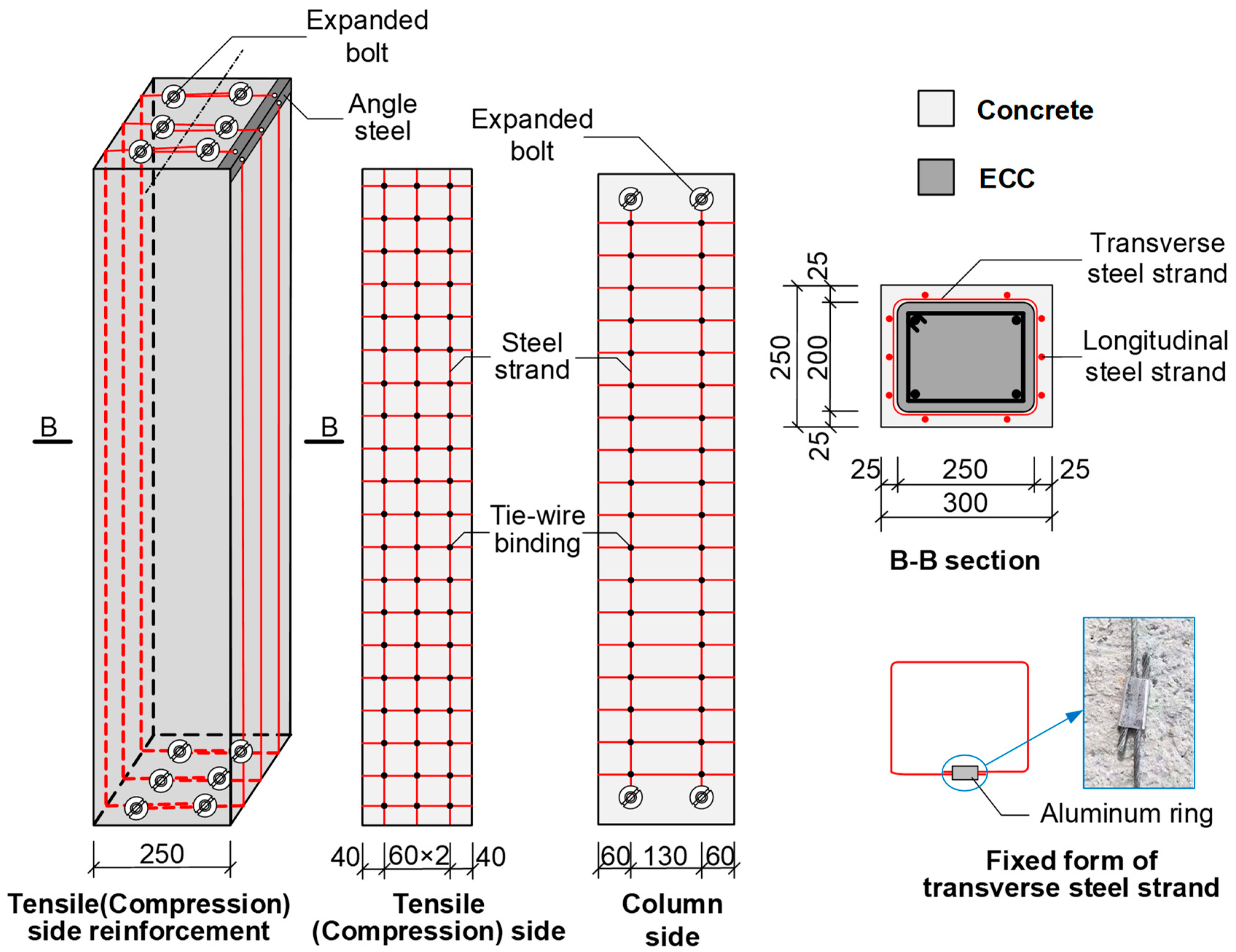
2.1. Description of Specimens

A total of six RC columns were tested against small eccentric compressions in this research. The cross-section sizes of all original columns were width × depth = 200 mm × 250 mm and the height was 1200 mm. For each specimen, four steel bars with the diameter of 14 mm were used as longitudinal reinforcement; meanwhile, ribbed steel stirrups with a diameter of 8 mm were designed as transverse reinforcement with the spacing of 100 mm, which meets the requirements of the GB 50010-2010 “Code for Design of Concrete Structures” [21]. The stirrups at both ends of the column were designed to be 50 mm to avoid local compression failure during the stress concentration at the top and bottom of the columns. Because the section size of the strengthened RC column is larger than that of the unstrengthened column, the initial eccentricity ratio is relative to the initial eccentricity ratio e0/h (for the strengthened column, h is the section height of the strengthened column, h = d + 2s, and s is the thickness of the reinforced layer, which is 25 mm), hence the section size after reinforcement was 250 mm × 300 mm, and the reinforced column is shown in Figure 1.
This test was designed to study the influence of the reinforcement methods, initial eccentricity ratio, and reinforcement ratios of a longitudinal high-strength stainless steel strand on the small eccentric compression performance of reinforced RC columns. The detailed information of the six specimen is shown in Figure 2 and Table 1.
In Table 1, SC means the strengthened column. In columns with different reinforcement methods, E means using ECC strengthened method, and H means using high-strength stainless steel stranded wire mesh-ECC strengthened method. The number in the front represents the number of longitudinal high-strength stainless steel stranded wires on the tension (compression) side, and the number behind represents the initial eccentricity ratio of the reinforced column. For example, SCH3-0.22 represents the RC column strengthened with high-strength stainless steel stranded wire mesh-ECC and the number of longitudinal high-strength stainless steel stranded wires on the tension (compression) side is three, and the initial eccentricity ratio is 0.22 h.

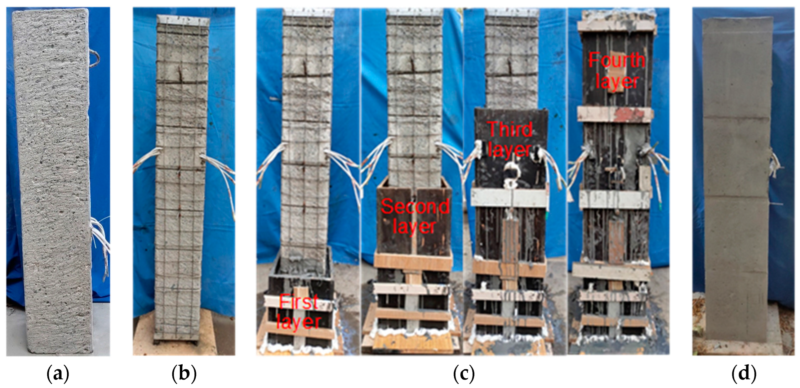
2.2. Fabrication of Test Specimens

According to relevant regulations in the GB 50367–2013 “Code for Design of strengthening Concrete Structures” [22], small eccentric compression columns were reinforced by the enclosure method. The high-strength stainless steel stranded wire mesh was placed outside the column, including transverse steel strands and longitudinal steel strands. The longitudinal steel strands were arranged on both compression and tension sides of the strengthened column, and longitudinal steel strands were anchored at the bottom and top of the column with angle steel to prevent the early pull-out failure, making full use of the tension strength of longitudinal steel strands. For RC columns in the actual existing projects, the planting reinforcement method can be used for anchorage [23]. The distance between the longitudinal steel strands on the tensile and compression sides from the column edge was 40 mm and the thickness of the ECC layer was design to be 25 mm, which meets the requirement [22]. The reinforcement details of the small eccentric compression column is shown step by step in Figure 3:
Firstly, the surface of the RC column was chiseled to expose the coarse concrete aggregate. The column angle was ground into the arc (chamfer radius is 15 mm), then continued into the groove, and the concrete interface after treatment was washed with water, as shown in Figure 3a.
Secondly, the transverse steel strands were first installed on the surface of the treated specimen and connected with aluminum rings at both ends, as shown in Figure 2 and Figure 3b. Then, one end of the longitudinal steel strands were fixed with an expansion bolt, and the steel strands were tightened and fixed at the other end, after that, they were tied with a transverse steel strand through tie wires. In the construction process of installing steel wire mesh, it was necessary to punch holes in the column to fix angle steels, which would cause concrete particles and floating dust to adhere to the surface of the column, so surfaces of RC columns must be cleaned again with water and alcohol.
Thereafter, the interface agent was uniformly sprayed on the surface of the RC column after cleaning the surface. Formwork was constructed before casting ECC, and after that, the designed ECC was poured in layers along the column height, as shown in Figure 3c.
Finally, after the casting was finished, the column was kept wet in the standard environment and covered with coating film to cure for 28 days, as shown in Figure 3d.

2.3. Material Properties

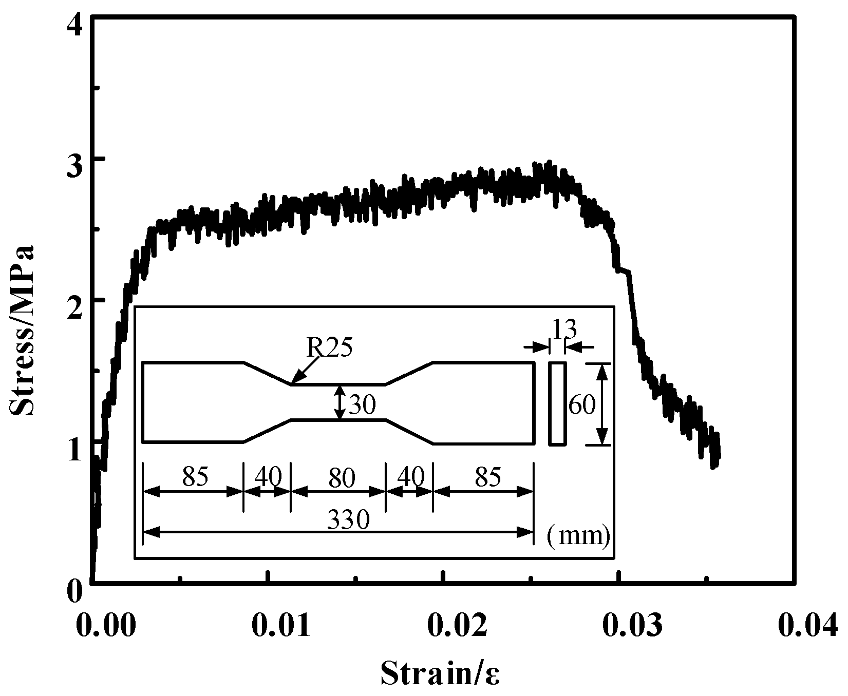
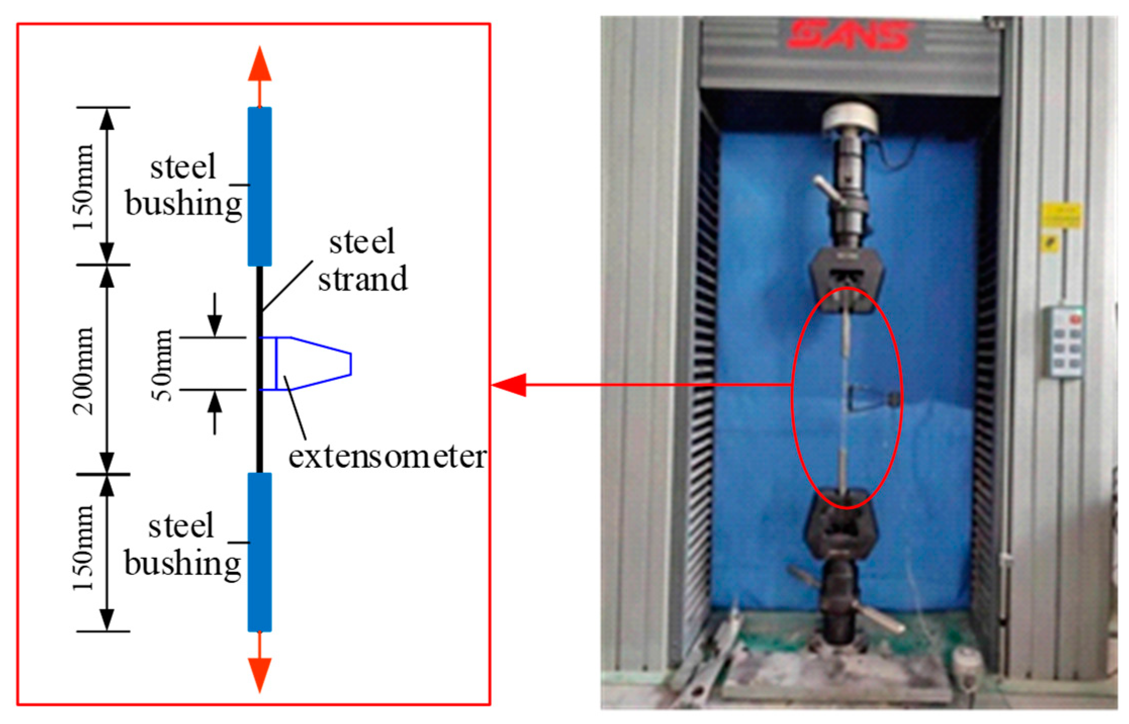
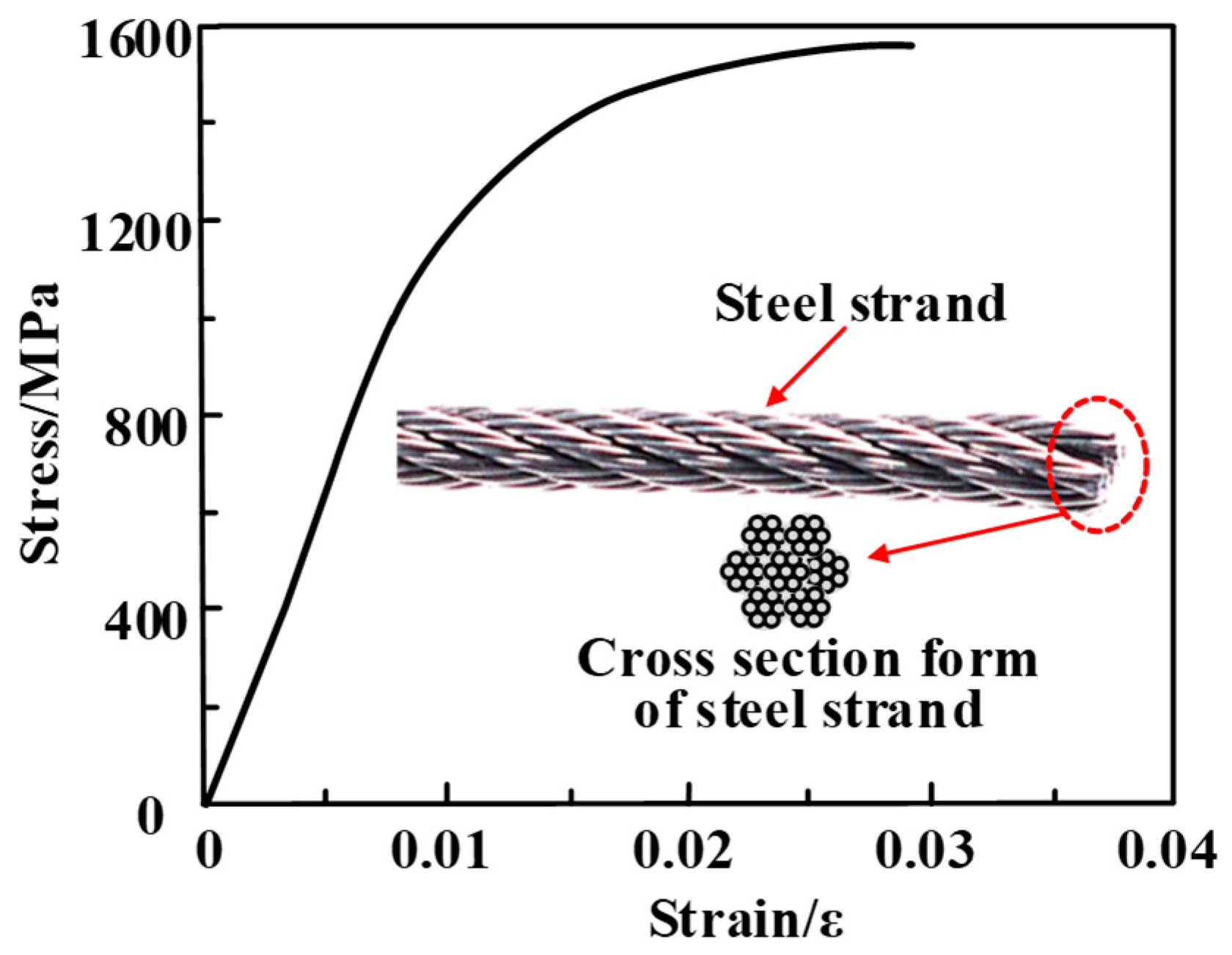
2.3.1. ECC and Strand

The mixture ratio of ECC in mass used in the test is shown in Table 2, and the physical and mechanical indicators of PVA fibers are shown in Table 3. When casting strengthened RC columns, for each reinforced specimen, a group of three ECC cubes with the size of 70.7 mm × 70.7 mm × 70.7 mm and three dog-bone shaped tensile specimens were cast and cured under the column under the same conditions. After the curing, the compressive and tensile strengths of ECC were tested, as shown in Figure 4. The typical tensile stress-strain curves of ECC are shown in Figure 5. The tensile strength, ultimate tension strain and compressive strength of ECC is 2.86 MPa, 3%, and 34.62 Mpa, respectively.
The nominal diameter of the steel strands inside the ECC reinforcement layer was 2.4 mm. Three specimens of 200 mm long steel strands were designed, and the tensile test was carried out as shown in Figure 6. The tensile stress-strain curve of the steel strand obtained from the test is shown in Figure 7. The elastic modulus measured by the test was 1.28 × 10² GPa, the ultimate tensile strength was 1546.5 MPa, and the ultimate tensile strain was 2.90%.

2.3.2. Concrete and Steel Bars

The strength grade of the concrete used in this test is C45. According to the “Standard for Test Methods for Concrete Physical and Mechanical Properties” [24], three standard cubes with dimensions of 150 mm × 150 mm × 150 mm were cast during the pouring process of the tested columns and cured for 28 days under the same conditions. The average and standard cube compressive strength was 45.9 MPa and 45.3 MPa, respectively. The mechanical properties of steel bars were tested by provisions of “Metallic materials—Tensile testing—Part 1: Method of test at room temperature” [25]. The mechanical properties of steel bars are shown in Table 4.

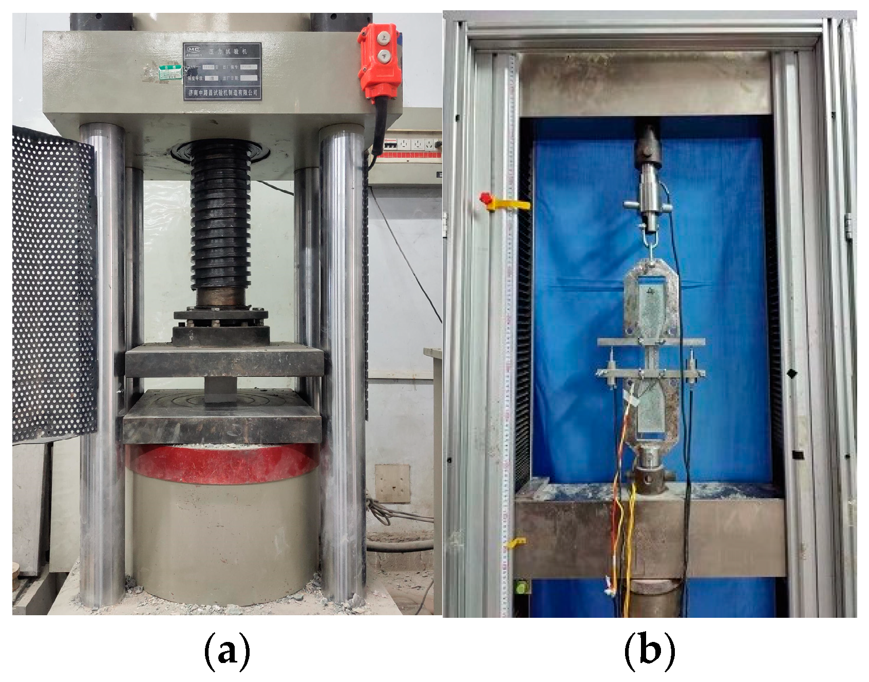
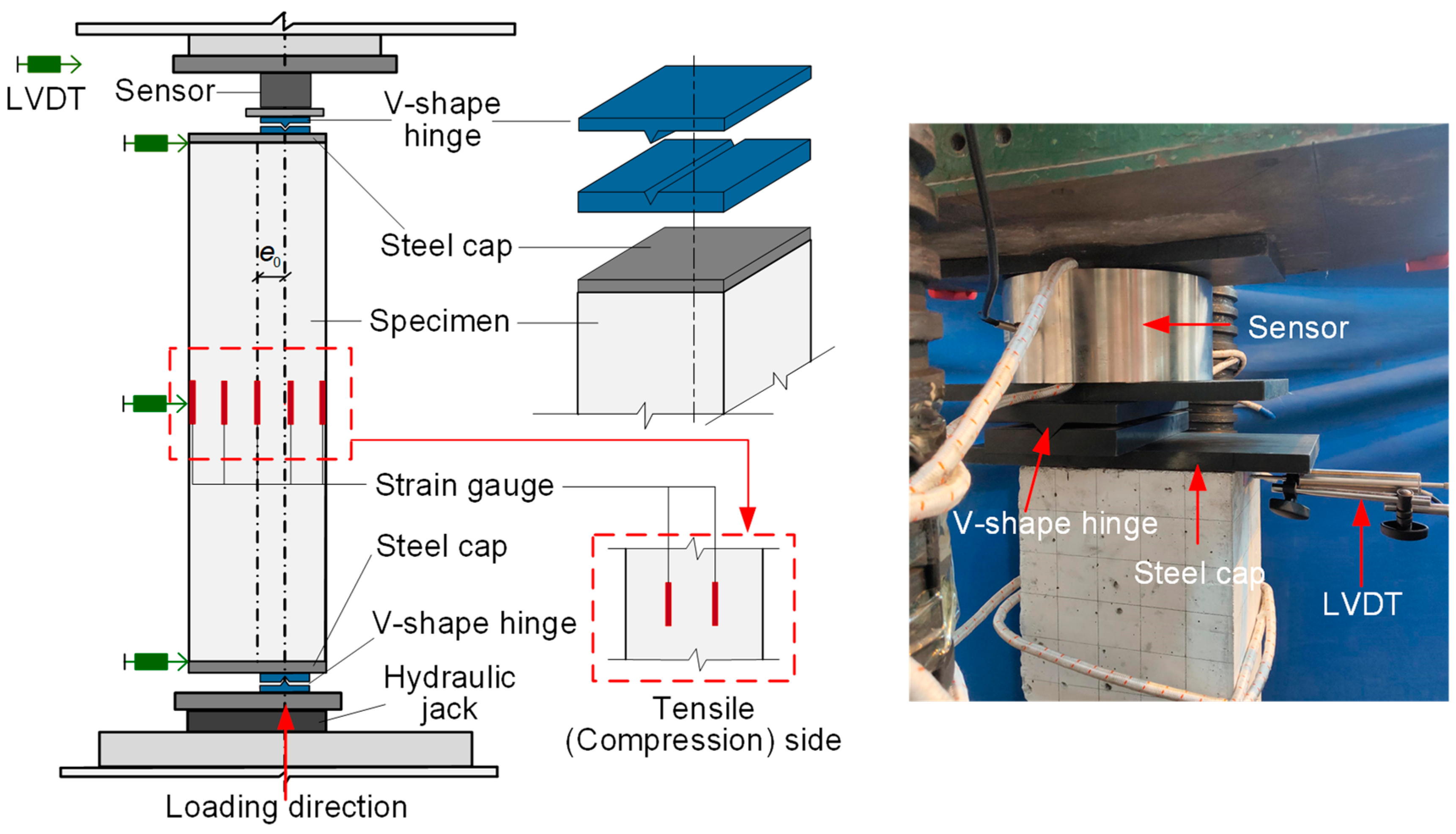
3. Test Setup and Loading Method

All specimens were loaded on a 5000 kN pressure testing machine using load grading control, the loading device is shown in Figure 8. Knife hinge supports were installed at both ends of the column to monitor the boundary condition of the hinged column end. The loading of different eccentric distances was realized by changing the position of the knife hinge supports, as shown in Figure 8. Referring to the relevant requirements of the “Standards for Test Methods of Concrete Structures” [26], before the formal loading was applied, the specimen was be checked in center and preloaded to ensure that the test device was in normal working condition. The amplitude of increasing loading of each stage was about 10% of the estimated peaking load, and the amplitude was decreased to the half after the loading increased to 70% of the estimated peaking load, which was 5% of the estimated peaking load. During the loading process, the applied load was controlled to increase uniformly and slowly and was maintained for 5 min when the target value was reached in order to collect the test data and observe phenomenon and then proceed to the next loading stage. After reaching the peaking load, the loading continued until the specimen obviously failed or the bearing capacity was dropped to 70% of the peaking load.

4. Experimental Results

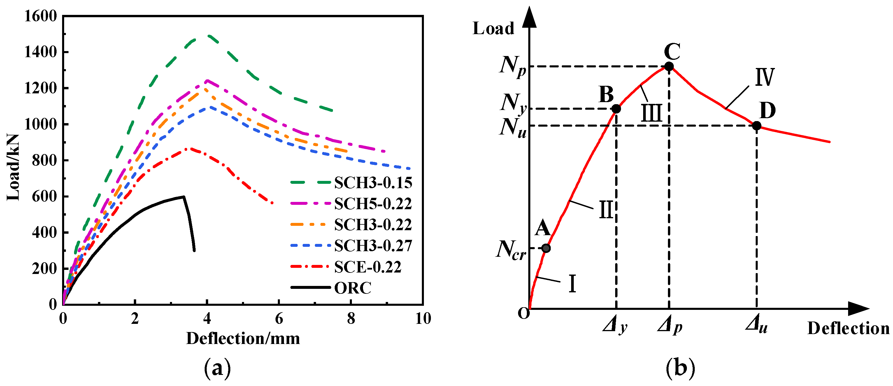
4.1. Load-Deflection Relationships

The mid-span lateral deflection of the specimen ORC (unreinforced column) when the concrete was crushed was 3.16 mm; however, the mid-span lateral deflection of the RC columns strengthened with ECC and the high-strength stainless steel wire mesh-ECC-reinforced column when the ECC was crushed was 5.09 mm and 6.62–7.69 mm, respectively. Compared with the unreinforced column, the ECC-reinforced column exhibited certain ductile failure characteristics, and it also had obvious flexural deformation, while the ductile failure characteristics of the high-strength stainless steel wire mesh-ECC-reinforced column were more obvious.
Figure 9a shows the load-midspan deflection curve of each specimen. Summarizing the load-midspan deflection curves of the reinforced column in Figure 9a, the typical large eccentric load-midspan deflection curve of the reinforced column was obtained, as shown in Figure 9b. The typical curve of reinforced columns can be divided into five stages based on the different shapes of curves and mechanical mechanisms, as shown below:
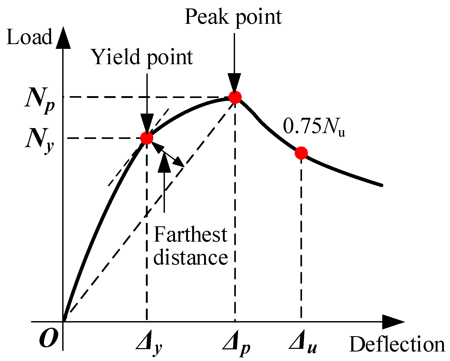
  • The elastic stage (OA stage): Before ECC cracking on the tensile side of the specimen, the whole section carried the applied load and the curve was nearly in line. When the first crack appeared and the curve reached point A (about 25% of the peaking load), the corresponding load applied on the specimen at this time was defined as the cracking load, and the section was in the limit state of cracking, and stage I ended;
  • The elastic-plastic stage (AB stage): After the specimen cracking, with the increase of applied load, small cracks appeared on the surface of the tensile side of the specimen continuously. However, due to the bridging function [27,28,29] of the fiber inside the ECC, the ECC of the reinforced layer on the tensile side could continue to resist the tension load after cracking. The specimen was into the elastic-plastic stage, which had the longest duration in the ascending stage. When it reached point B (about 80% of the peaking load), the curvature changed obviously. Point B was defined as the yielding point of the specimen, and the corresponding load applied on the specimen was the yielding load, and stage II ended;
  • The plastic stage (BC stage): With the further increase of the applied load, no new cracks were observed on the surface of the tensile side of the specimen, but the crack width increased slightly, and vertical cracks began to appear on the surface of the compression zone. The growth rate of midspan lateral deflection increased, and the specimen showed obvious plastic deformation. When it reached point C (peaking load), the specimen carried the maximum load, and stage III ended;
  • Descending stage (CD stage): Since the concrete in the compression zone was first crushed (because the ultimate compressive strain of ECC was far greater than the ultimate compressive strain of confined concrete), the lateral deflection of the midspan increased rapidly, and the ECC on the compression side was gradually crushed. When reaching point D (about 75% of the peaking load), the bottom of ECC on the compression side were crushed and the core transverse steel strands began to be broken. At this moment, the load continued to decrease and the midspan lateral deflection increases rapidly. Point D was the obvious reverse bending point in stage IV (falling section), and the state of point D was defined as the limit state of the specimen.

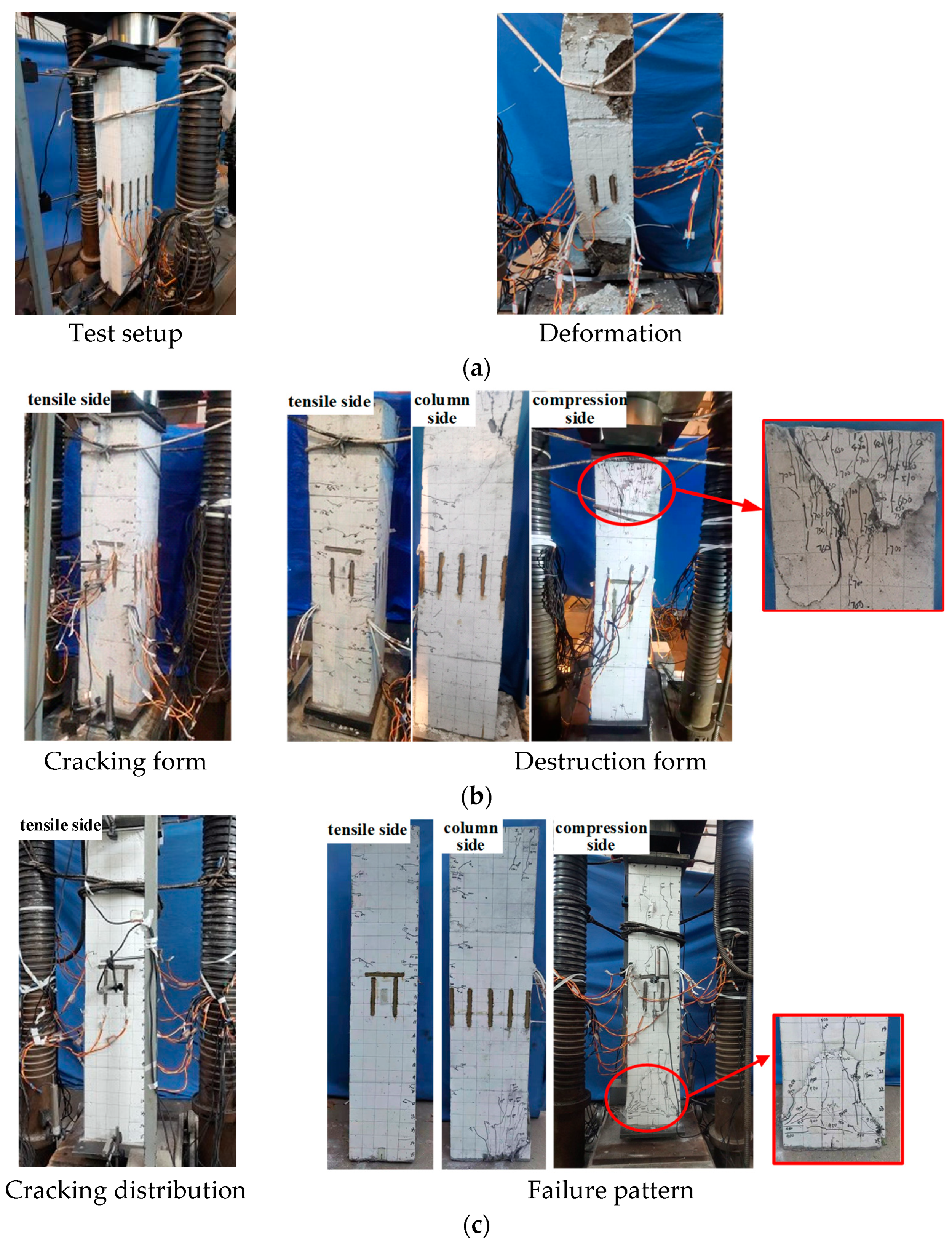
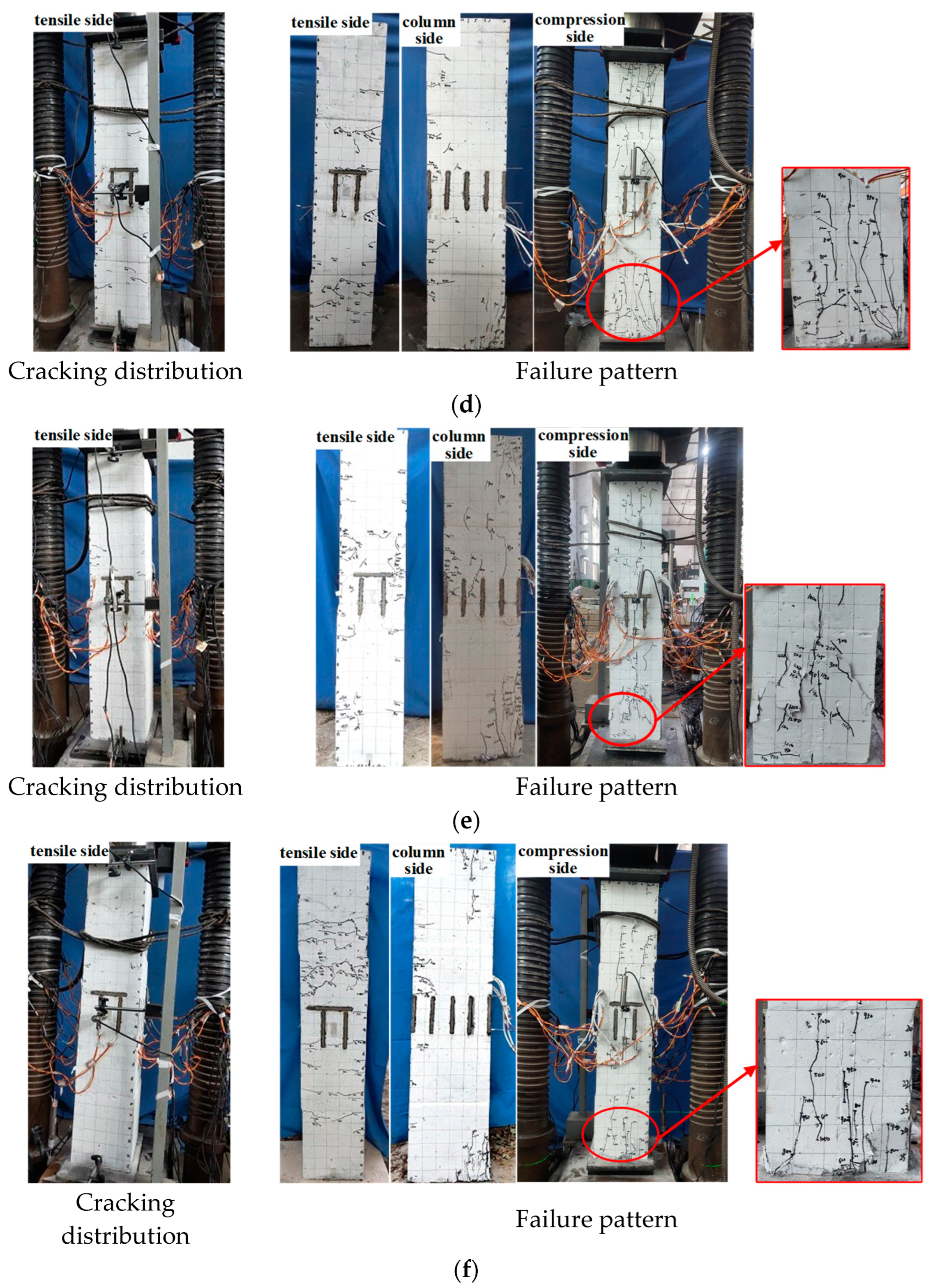
4.2. Cracks Pattern and Failure Models

The ultimate failure mode of the unreinforced RC column (ORC) was that the concrete was crushed at the bottom and top corner of the compression side; however, several longitudinal bars yielded under compression, which was the typical small eccentric compression brittle failure. The failure pattern is shown in Figure 10a. When the ECC-reinforced column (SCE-0.22) reached the peaking load, the maximum vertical crack width on the compression side was about 0.25 mm. The ultimate failure mode was ECC bulging at the top of the compression side, which is shown in Figure 10b, while the high-strength stainless steel wire mesh-ECC-reinforced column showed similar mechanical characteristics and failure characteristics, as shown in Figure 10c–f. When the peaking load was reached, the maximum vertical crack width of the compression side was only 0.20 mm, which met the requirements of the crack width in the serviceability limit state in the “Code for Design of Strengthening Concrete Structure” [22], and the failure process developed slowly. The ultimate failure mode was that vertical main cracks appeared at the bottom and corners on the compression side, and numerous small cracks were observed around the main cracks, parts of the ECC was crushed. Compared with the unreinforced RC column and the ECC strengthened RC column, the overall performance of the RC small eccentric compression column strengthened with steel wire mesh reinforced ECC was much better.

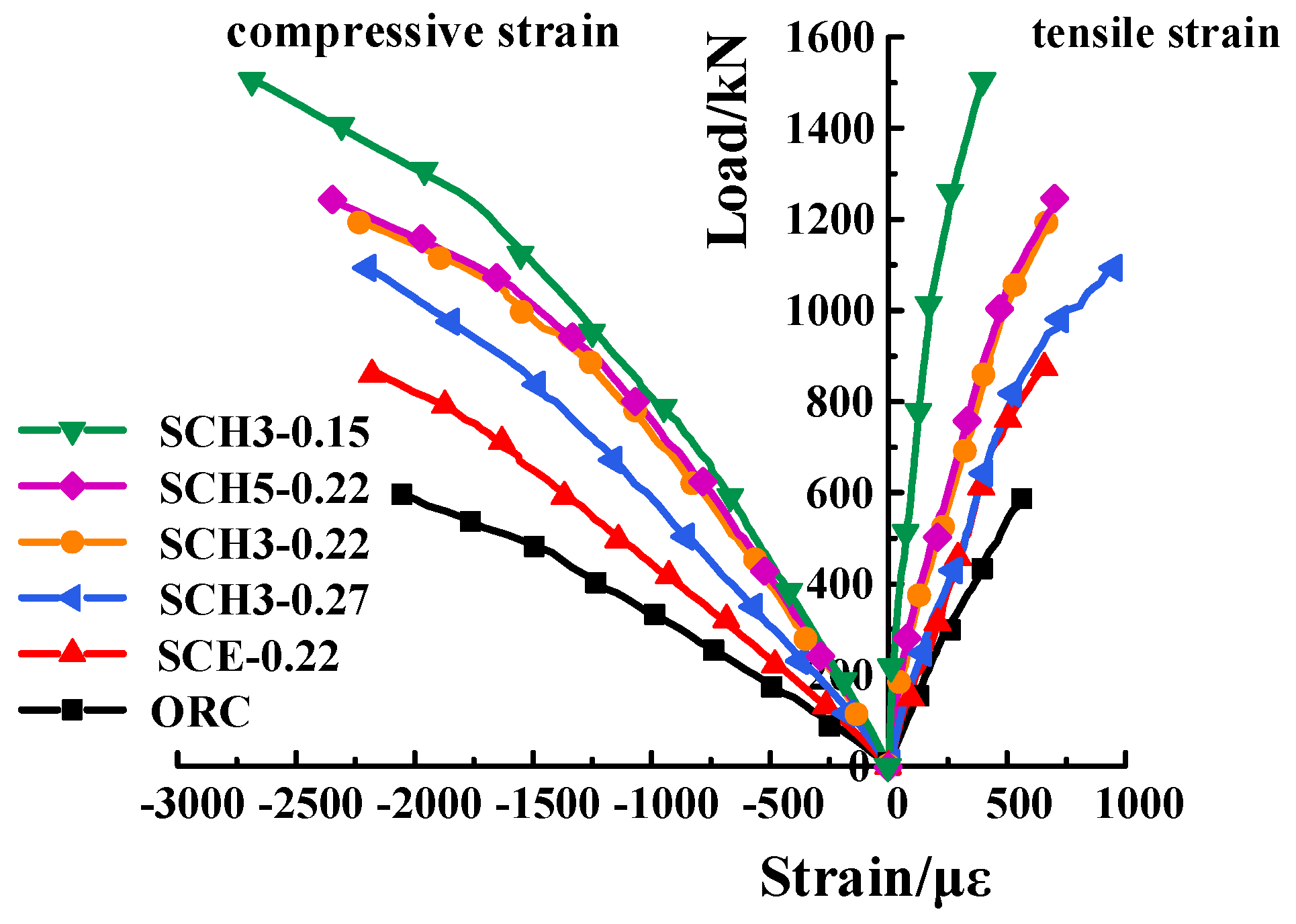
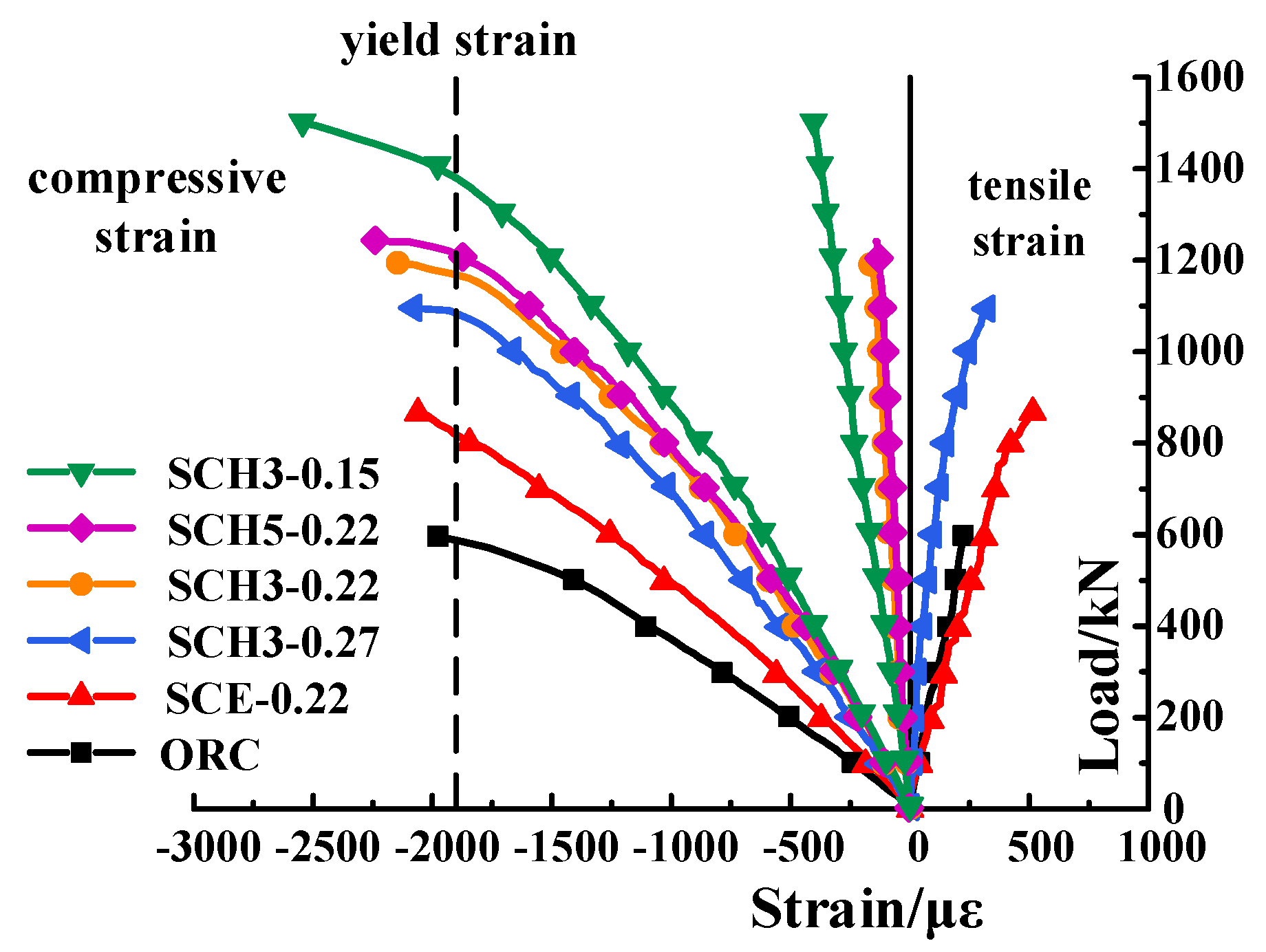
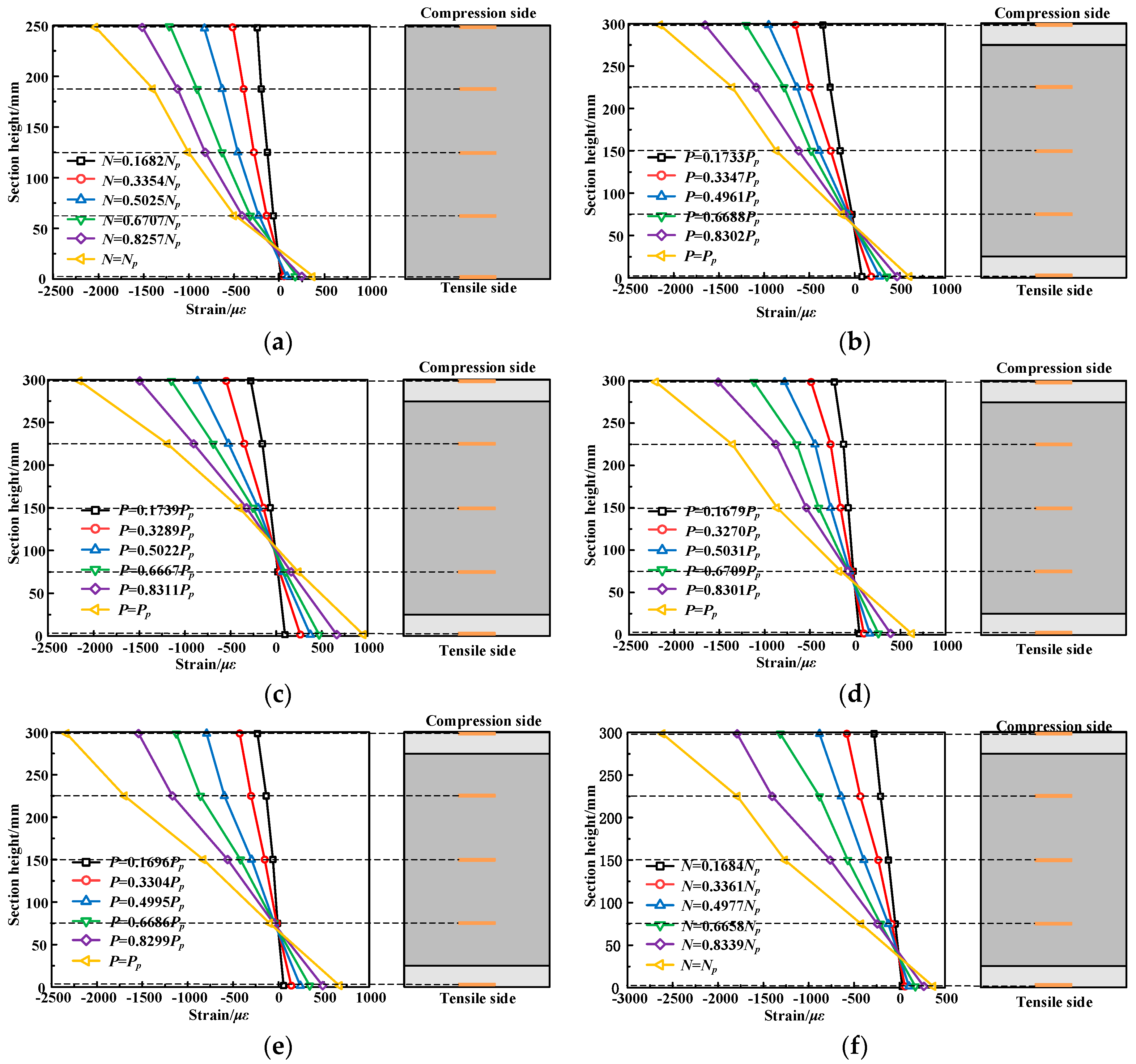
4.3. Strain of ECC/Concrete and Rebars

Based on the test data, the load-strain curves of the concrete of the unreinforced column and the ECC of the reinforced column were drawn and compared, as shown in Figure 11. When the load was small, the concrete strain of the unreinforced column and the ECC strain of the reinforced column was also small, which was in the elastic stage (OA stage in Figure 9a), and the strain increases approximately proportionally with the increase of applied load. As the load increased to about 80% of the peaking load, the specimen began to enter the plastic deformation stage, that is, the OA stage of Figure 9a, the slope of the load-strain curve of the specimen decreases gradually and the strain began to increase rapidly. Based on the comparison the load-strain curves of columns SCE-0.22, SCH3-0.22, and SCH5-0.22, it can be seen that under the same load, the ECC strain of the stainless steel wire mesh-ECC-reinforced column was significantly lower than that of the ECC-reinforced column, indicating that the stainless steel wire mesh-ECC-reinforced layer can effectively delay the cracking and damage of concrete (ECC).
It can be seen from Figure 12 that the longitudinal bars on the compression side all maintained a linear growth before yielding. After yielding, the load increased slowly and the strain increased rapidly; while the strain of the longitudinal bars on the tensile side was small and did not reach yielding stage. This was consistent with the situation of ordinary reinforced concrete columns under small eccentric compression. When the initial eccentricity ratio was small, the longitudinal reinforcement on the side far from the loading point of the reinforced column (SCE-0.22, SCH3-0.22, SCH5-0.22) changed from the tensile state before the reinforcement to the compressive state after reinforcement. This was because the cross-sectional area became larger after reinforcement and the distance from the side longitudinal reinforcement to the tension edge became larger. Under the same load, compared with the unreinforced column and the ECC-reinforced column, the compressive strain of the longitudinal bars of the stainless steel wire mesh-ECC-reinforced column was smaller. This shows that the stainless steel wire mesh-ECC-reinforced layer can improve the bearing capacity of small eccentric compression columns.

4.4. Ductility

Ductility refers to the plastic deformation ability of the RC structure or member, and the ductility coefficient is a common index to measure the ductility, which is defined as μ = Δu/Δy [30], where Δu is the ultimate displacement, and reference [31] takes the mid-span lateral displacement corresponding to the load decreased to 75% of the peaking load; Δy is the mid-span lateral displacement at the yielding point. The yielding point is determined by the farthest point method in reference [32], as shown in Figure 13. The calculation results of the ductility coefficient of specimens are shown in Table 5.
It can be seen from Table 5 that the ductility of the reinforced column is significantly improved compared with that of the unreinforced column. Among them, compared with specimen ORC, the SCE-0.22 of the ECC-reinforced column was increased by 50.0%, and specimens SCH3-0.22 and SCH5-0.22 of the stainless steel wire mesh-ECC-reinforced column were increased by 75.6% and 77.8%, respectively. It demonstrates that compared with the ECC-reinforced method, the stainless steel wire mesh-ECC-reinforced method could more significantly improve the ductility of RC columns under small eccentric compression. The reasons are that, after reaching the peaking load, the stainless steel wire mesh-ECC-reinforced column exhibited a large flexural deformation, and the core concrete showed a large transverse expansion deformation, accompanied with the slow decreasing of the applied load. During this process, the transverse steel wire in the reinforced layer provided effective constraints to the core concrete, and stainless steel wire mesh-ECC-reinforced layer did not peel off from the concrete interface; therefore, the ductility of the specimen was obviously improved. The comparison of columns SCH3-0.22 and SCH5-0.22 showed, however, that when the reinforcement ratio of longitudinal steel strand increased from 0.1692% to 0.2820%, the ductility coefficient of column SCH5-0.22 was only 1.1% higher than that of column SCH3-0.22. The reason for this is that the eccentricity ratio of the test column was small and the tensile stress of the tensile side stainless steel strand was also small. The comparative analysis of columns SCH3-0.15, SCH3-0.22, and SCH3-0.22 showed that a larger initial eccentricity ratio resulted in the better ductility of the tested specimen.

5. Parametric Analysis

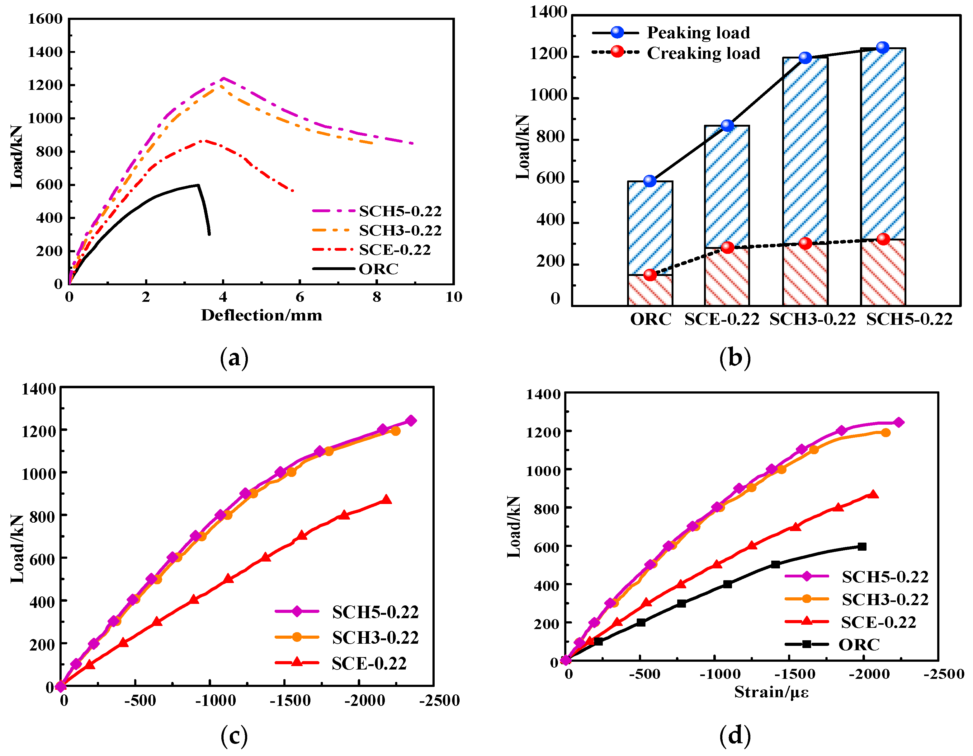
5.1. Reinforcement Method

Based on the test data, the comparison curves of the unstrengthened column (ORC), ECC-reinforced column (SCE-0.22), and steel wire mesh-ECC-reinforced column (SCH3-0.22, SCH5-0.22) with the same eccentricity ratio are drawn as shown in Figure 13. It can be seen from Figure 14a that under the same load, the mid-span lateral deflection of the unreinforced column is the largest, followed by that of the ECC-reinforced column, and that of steel wire mesh-ECC-reinforced column was the smallest, indicating that the stiffness of the reinforced column is improved. The arrangement of steel wire mesh-ECC-reinforced layer can further effectively constrain the lateral deformation of the specimen. It can be seen from Figure 14b that the cracking load and peaking load of the strengthened columns have been effectively improved. Compared with the ECC-strengthened column, the peaking load of the steel wire mesh-ECC-reinforced column increases more significantly, but the cracking load increases less than that of the ECC-reinforced column. From Figure 14c,d it can be seen that under the same load the ECC strain on the compression side of the steel wire mesh-ECC-reinforced column is significantly lower than that of the ECC-reinforced column. The compressive strain of the longitudinal bars in the unreinforced column is the largest, followed by the ECC-reinforced column, and the steel wire mesh-ECC-reinforced column is the smallest. This shows that the steel wire mesh-ECC-reinforced column can more effectively delay the cracking of specimens and the damage of the ECC, and improve the bearing capacity of RC small eccentric compression columns, and its reinforcement effect is better.

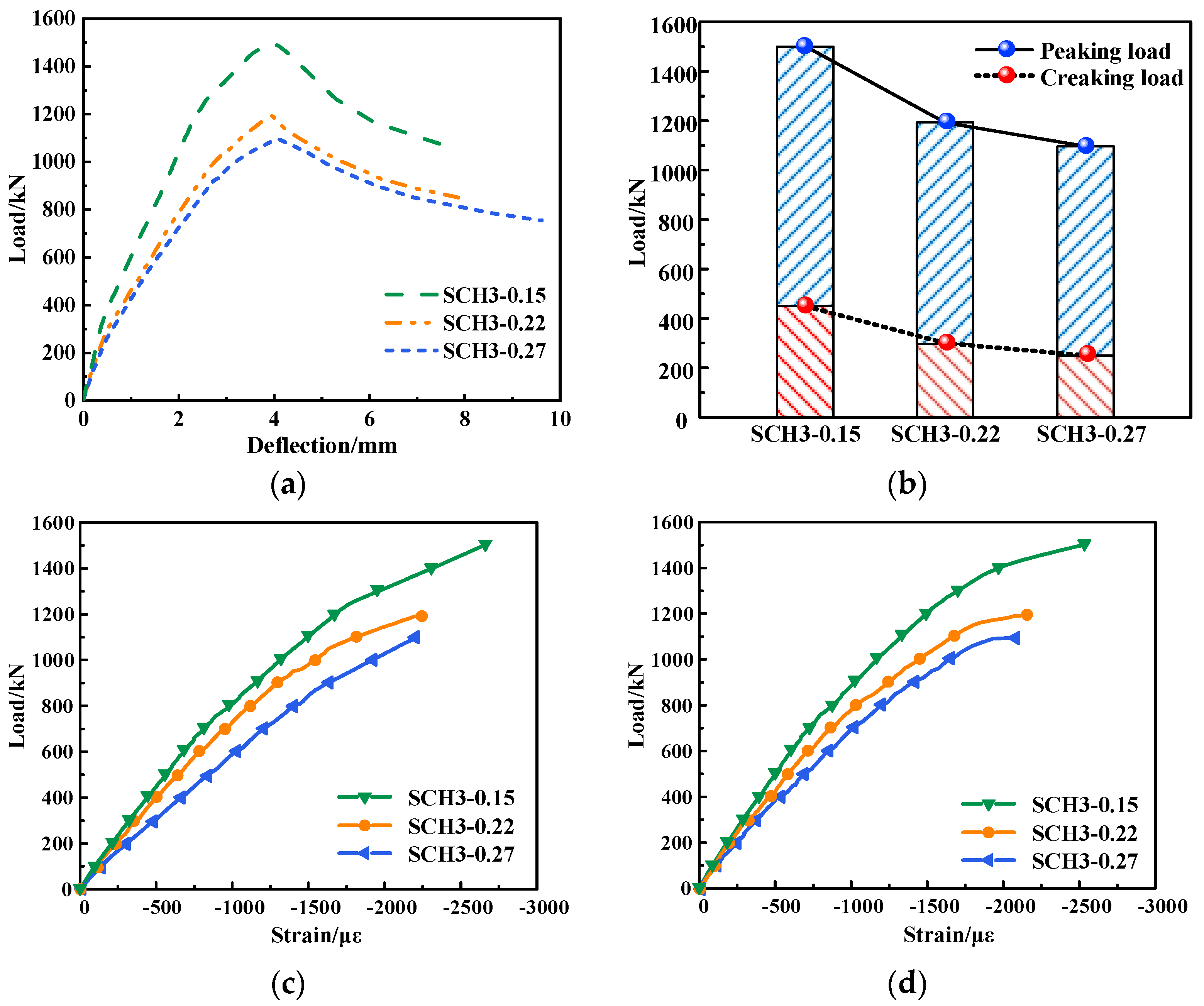
5.2. Eccentricity Ratio

Based on the test data, the comparison curves of RC columns with different reinforcement ratios of longitudinal steel strands (0.1692%, 0.2820%) were drawn, as shown in Figure 15. When the reinforcement ratio of longitudinal steel strands increases from 0.1692% to 0.2820%, the increase of cracking load of the specimen is small. The increase of mid-span lateral deflection of reinforced column (SCH5-0.22) with the larger longitudinal reinforcement ratio is slower than that of reinforced column (SCH3-0.22) with the smaller longitudinal reinforcement ratio. The peaking load of the reinforced column with the longitudinal steel strand reinforcement ratio of 0.2820% is only 4.1% higher than that of the reinforced column with the longitudinal steel strand reinforcement ratio of 0.1692%, indicating that the longitudinal reinforcement ratio and the increase of the peaking load is limited. As shown in Figure 15c,d, increasing the longitudinal reinforcement ratio of the reinforced column, the compressive strain growth trend of ECC on the compression side of the specimen is the same, and the load-longitudinal bar compressive strain curve has no obvious change, indicating that the change of the longitudinal reinforcement ratio has little effect on the deformation capacity of reinforced RC columns.

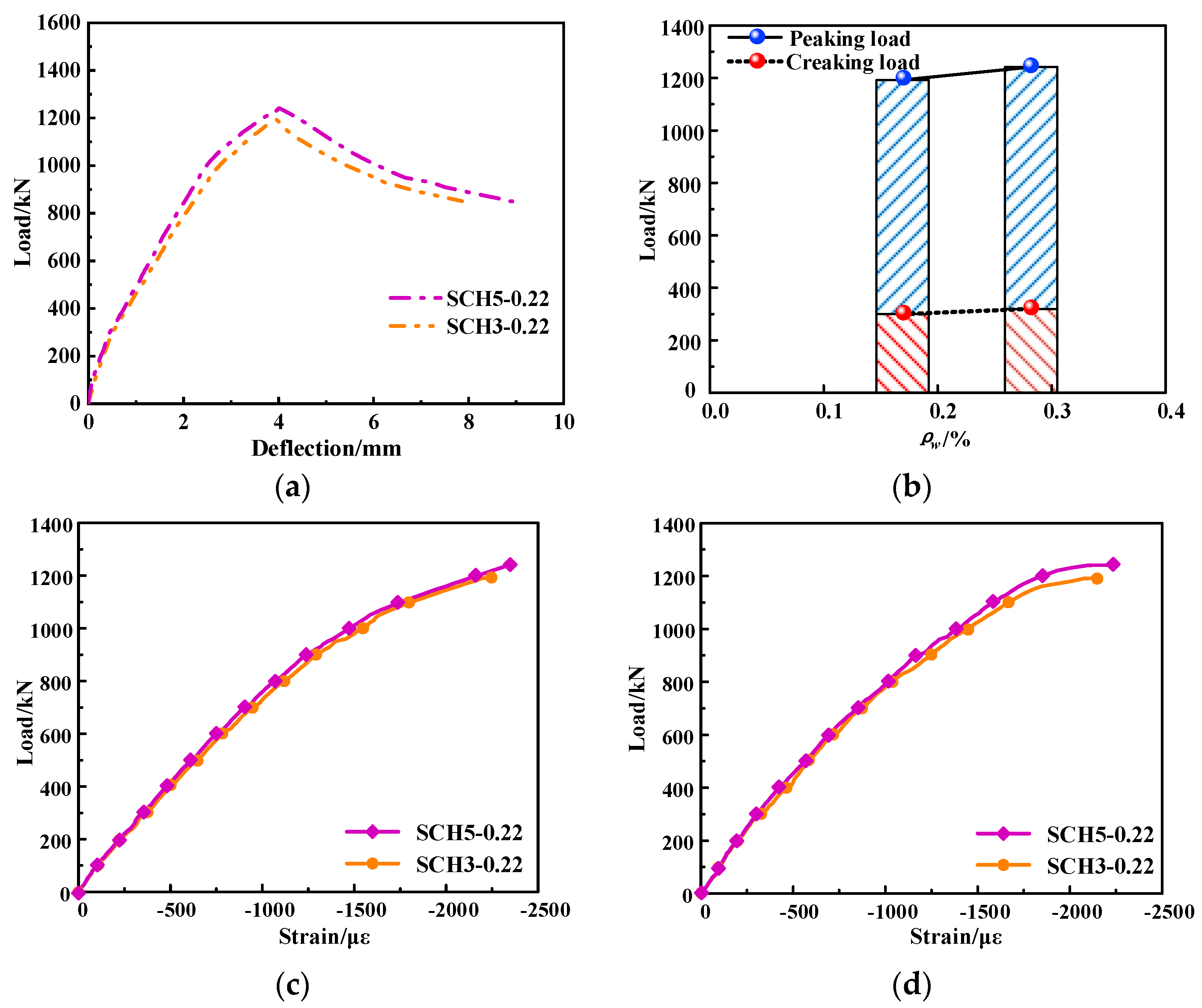
5.3. Reinforcement Ratio of High-Strength Stainless Steel Strand

Based on the test data, the comparison curves of steel wire mesh-ECC-reinforced columns with different eccentricities are shown in Figure 16. The eccentricity ratio has little effect on the elastic stiffness of the column at the initial stage of loading. With the increase of load, the specimen gradually enters the elastic-plastic stage, and the stiffness of the specimen with small eccentricity ratio is significantly greater than that of the specimen with large eccentricity ratio. The eccentricity ratio has an important influence on the deformation of the specimen. Under the same load, with the increase of eccentricity ratio, the mid-span lateral deflection of columns increase, and the load dropping stage especially tends to be flatter, indicating that the larger the eccentricity ratio is, the better the ductility of the reinforced specimen is. In addition, it can be seen from Figure 16b that the eccentricity ratio also has an important influence on the bearing capacity. The larger the eccentricity ratio is, the smaller the cracking load and peaking load of the specimen are. It can be seen from Figure 16c that the development trend of the load-ECC compressive strain curve of the steel wire mesh-ECC-reinforced column with different eccentricities is similar. In other words, at the beginning of loading, the ECC compressive strain of the compression side increases linearly. With the increasing load, the slope of the load-ECC compressive strain relationship curve decreases continuously. When it is close to the peaking load, the ECC compressive strain increases significantly faster. From Figure 16d, it can be seen that the eccentricity ratio has little effect on the compressive strain curve of the longitudinal reinforcement of the load-compression side at the initial stage of loading, which is roughly linear growth. Under the same other conditions, the larger the eccentricity ratio, the lower the bearing capacity of the column, and the compression-strain curve of the longitudinal reinforcement on the load-compression side tends to be flatter. Under the same load, with the increase of eccentricity ratio, the compressive strain of ECC and the compressive strain of compression side longitudinal reinforcement increase.

6. Mechanical Mechanism and Load-Carrying Capacity Analysis

The strain diagram of the mid-span section of each specimen is drawn, as shown in Figure 17. The analysis of Figure 17b–e shows that as the load increases step by step, the neutral axis (where the compression stress and tension stress are zero) gradually moves down, resulting in the greater compression zone; however, the value of the moving range is very small. The reasons are as follows: with the increase of the applied load, after the ECC and concrete on the tensile side are cracked, the neutral axis moves towards the compression zone; meanwhile, the height of the compression zone gradually decreases. When the peaking load is reached, the specimen with the larger the initial eccentricity ratio obtained the larger the tensile zone. During the whole staged loading process, the section strain was roughly linearly distributed, and the strain distribution in the mid-span section of the specimen conforms to the assumption of the plane section.
Based on the test results and analysis, it can be seen that the bearing capacity of the high-strength stainless steel wire mesh-ECC-reinforced column under the small eccentric compression load is composed of three parts: the bearing capacity provided by the high-strength stainless steel wire mesh-ECC-constrained core RC column, the bearing capacity provided by ECC on the compression side of the reinforcement layer (maximum compression side), and the bearing capacity provided by the longitudinal steel strands on the tensile side of the reinforcement layer. The compressive capacity of the longitudinal steel strands and the ECC capacity of the lateral compression zone on the side of the reinforcement layer can be ignored in the calculation of the bearing capacity of the stainless steel wire mesh-ECC-reinforced column.

7. Conclusions

In this research, the main parameters of the reinforcement method, the longitudinal steel strand reinforcement ratio and the eccentricity ratio, are used to conduct compression tests on six RC columns with small eccentric compression loads. The effects of the reinforcement method, longitudinal steel strand reinforcement ratio, and eccentricity ratio on mechanical properties, such as crack distribution, ductility, failure mechanism, and bearing capacity, of stainless steel wire mesh-ECC-reinforced column are investigated and compared. Based on the test results, the following main conclusions can be drawn below:
  • The stainless steel wire mesh-ECC-reinforced layer and the concrete interface are effectively bonded because of the adopted treatment, and they work together well. The stainless steel wire mesh-ECC-reinforced layer can provide an effective constraint for the core concrete in the compression zone, and the core concrete in the compression zone is in a three-dimensional compression state. This contributed to the significant increase of its compressive strength and ductility, which significantly improves the overall mechanical performance of strengthened RC columns;
  • The stainless steel wire mesh-ECC-reinforced layer can effectively delay and restrict the development of cracks on the surface of the RC column and reduce the maximum crack width. When the peaking load is reached, the concrete in the compression zone is crushed first, and the reinforcement layer ECC on the compression side is gradually crushed with the decrease of applied load, which has an obvious portent and shows good ductile failure characteristics;
  • Compared with the unreinforced column, the cracking load and peaking load of the stainless steel wire mesh-ECC-reinforced column are significantly improved, the cracking load is increased by 100.0–113.3%, and the peaking load is increased by 99.8–108.0%. Compared with the ECC-reinforced column, its cracking load increased by 7.1–14.3% and the peaking load increased by 37.6–43.3%. Moreover, the cracking and peaking load decreased with the increase of the eccentricity ratio; however, the variation of longitudinal reinforcement ratio has little effect on the reinforcement effect;
  • The ductility of the stainless steel wire mesh-ECC-reinforced column is 75.6–77.8% higher than that of the unreinforced column and 17.3–18.6% higher than that of the ECC-reinforced column. The ductility of the stainless steel wire mesh-ECC-reinforced column increased with the eccentricity ratio of tested specimen;
  • Based on the test results, the basic assumptions for the calculation of the bearing capacity of the stainless steel wire mesh-ECC-reinforced column are established.
  • In this paper, the test only considers three factors: reinforcement method, eccentricity, and longitudinal steel strand reinforcement ratio. The factors such as ECC strength, thickness of reinforcement layer, the reinforcement ratio of original column, and concrete strength are not studied. Therefore, the finite element model of reinforced RC columns can be established for numerical simulation analysis based on the experimental research in this paper.

Author Contributions

Conceptualization, X.W.; methodology, X.W., Y.L. and Y.Z.; formal analysis, Y.L. and Y.Z.; investigation, Y.L., Y.Z. and Y.W; resources, X.W. and J.F.; data curation, Y.L. and Y.Z.; writing—original draft preparation, Y.L.; writing—review and editing, J.F., Y.L. and Y.W.; visualization, Y.L.; supervision, J.F. and X.W.; project administration, X.W.; funding acquisition, X.W. and J.F. All authors have read and agreed to the published version of the manuscript.

Funding

This work was supported by grants from the National Natural Science Foundation of China (No. 51879243 and 52108183), Project funded by China Postdoctoral Science Foundation (No. 2021TQ0302 and 2021M702953), Key Scientific Research Projects of Universities in Henan Province (No. 22A560004), and Zhengzhou University Young talents Enterprise Cooperative Team Innovation Project (No. 32320407).

Institutional Review Board Statement

Not applicable.

Informed Consent Statement

Not applicable.

Data Availability Statement

All datasets presented in this study are included in the article.

Conflicts of Interest

The authors declare no conflict of interest.

References

  1. Li, V.C. Tailoring ECC for special attributes: A review. Int. J. Concr. Struct. Mater. 2012, 6, 135–144. [Google Scholar] [CrossRef] [Green Version]
  2. Fischer, G.; Li, V.C. Intrinsic response control of moment-resisting frames utilizing advanced composite materials and structural elements. ACI Struct. J. 2003, 100, 166–176. [Google Scholar]
  3. Li, V.C. On engineered cementitious composites (ECC) a review of the material and its applications. J. Adv. Concr. Technol. 2003, 1, 215–230. [Google Scholar] [CrossRef] [Green Version]
  4. Li, V.C. High performance fiber reinforced cementitious composites as durable material for concrete structure repair international. Int. J. Restor. 2004, 10, 163–180. [Google Scholar]
  5. Li, V.C.; Lepech, M. Crack resistant concrete material for transportation construction. In Proceedings of the TRB 83rd Annual Meeting, Wasgington, DC, USA, 11–15 January 2003. [Google Scholar]
  6. Liu, H.Z.; Zhang, Q.; Li, V.C.; Su, H.Z.; Gu, C.S. Durability study on engineered cementitious composites (ECC) under sulfate and chloride environment. Constr. Build. Mater. 2017, 133, 171–181. [Google Scholar] [CrossRef]
  7. Kojima, S.N.; Kanda, T.; Hiraishi, M. Application of directsprayed ECC for retrofitting dam structure surface-application for Mitaka-Dam. JCI Concr. J. 2004, 42, 135–139. [Google Scholar]
  8. Yu, J.H.; Niu, H.; Bao, L.; Ding, X.; Jia, L.G. Effect of Propogating and Kinking of Interfacial Crack on ECC-concrete Overlay Repair System. China J. Highw. Transp. 2013, 26, 44–50. [Google Scholar]
  9. Salahuddin, Q.; Mohamed, M. Application of Engineered Cementitious Composites (ECC) in interiorbeam–column connections for enhanced seismic resistance. Eng. Struct. 2014, 69, 235–245. [Google Scholar]
  10. Khan, M.K.I.; Rana, M.M.; Zhang, Y.; Lee, C.K. Behaviour of engineered cementitious composite-encased stub concrete columns under axial compression. Mag. Concr. Res. 2019, 72, 984–1005. [Google Scholar] [CrossRef]
  11. Li, X.; Chen, K.D.; Hu, P.; He, W.; Xiao, L.; Zhang, R. Effect of ECC jackets for enhancing the lateral cyclic behavior of RC bridge columns. Eng. Struct. 2020, 219, 110714. [Google Scholar] [CrossRef]
  12. Ioannou, A.I.; Pantazopoulou, S.J.; Petrou, M.F.; Charmpis, D.C. Experimental investigation of ECC jackets for repair of pre-damaged R.C. members under monotonic loading. Buildings 2021, 11, 180. [Google Scholar] [CrossRef]
  13. Al-Gemeel, A.N.; Zhuge, Y. Experimental investigation of textile reinforced engineered cementitious composite (ECC) for square concrete column confinement. Constr. Build. Mater. 2018, 174, 594–602. [Google Scholar] [CrossRef]
  14. Zheng, Y.Z.; Wang, W.W.; Mosalam, K.M.; Zhu, Z.F. Mechanical behavior of ultra-high toughness cementitious composite strengthened with Fiber Reinforced Polymer grid. Compos. Struct. 2018, 184, 1–10. [Google Scholar] [CrossRef]
  15. Yang, X.; Gao, W.Y.; Dai, J.G.; Lu, Z.D. Shear strengthening of RC beams with FRP grid-reinforced ECC matrix. Compos. Struct. 2020, 241, 112120. [Google Scholar] [CrossRef]
  16. Lin, K.J.; Yang, Y.H.; Chen, Z.W.; Sun, X.Y.; Wang, H.L. Experimental Study on Eccentric Compressive Performance of Concrete Column Strengthened with CFRP Grid Reinforced ECC Matrix. Adv. Civ. Eng. 2021, 2021, 8852445. [Google Scholar] [CrossRef]
  17. Emara, M.; Mohamed, H.A.; Rizk, M.S.; Hu, J.W. Behavior of ECC columns confined using steel wire mesh under axial loading. J. Build. Eng. 2021, 43, 102809. [Google Scholar] [CrossRef]
  18. Li, K.; Liu, W.K.; Zhang, K.; Wang, X.L.; Zhu, J.T.; Sheikh, S. Bond behavior of stainless steel wire ropes embedded in engineered cementitious composites. Constr. Build. Mater. 2021, 281, 122622. [Google Scholar] [CrossRef]
  19. Li, K.; Zhao, D.P.; Fan, J.J.; Zhu, J.T. Local Bond Stress-Slip Model of High-Strength Stainless Steel Wire Ropes in ECC. KSCE J. Civ. Eng. 2022, 26, 2259–2272. [Google Scholar] [CrossRef]
  20. Wang, X.L.; Yang, G.H.; Qian, W.W.; Li, K.; Zhu, J.T. Tensile behavior of high-strength stainless steel wire rope (HSSSWR)-reinforced ECC. Int. J. Concr. Struct. Mater. 2021, 15, 1–15. [Google Scholar] [CrossRef]
  21. GB 50010-2010; Code for Design of Concrete Structures. China Architecture & Building Press: Beijing, China, 2015.
  22. GB 50367-2013; Code for Design of Strengthening Concrete Structure. China Architecture & Building Press: Beijing, China, 2010.
  23. Shang, S.P.; Huang, X.Z.; Yang, T. Experiment on anchorage performance of planting rebar with rapid-solidification inorganic adhesive. J. Archit. Civ. Eng. 2019, 36, 13–21. [Google Scholar]
  24. GB/T 50081-2019; Standard for Test Methods for Concrete Physical and Mechanical Properties. China Architecture & Building Press: Beijing, China, 2010.
  25. GB/T 228.1-2010; Metallic Materials-Tensile Testing-Part 1: Method of Test at Room Temperature. Chinese Standard Press: Beijing, China, 2010.
  26. GB/T50152-2012; Standards for Test Methods of Concrete Structures. China Architecture & Building Press: Beijing, China, 2010.
  27. Elhadary, M.; Hamdy, A.; Shaker, W. Effect of fiber bridging in composites healing. Alex. Eng. J. 2022, 61, 2769–2774. [Google Scholar] [CrossRef]
  28. Khaloo, A.; Daneshyar, A.; Rezaei, B.; Fartash, A. Fiber bridging in polypropylene-reinforced high-strengthconcrete: An experimental and numerical survey. Struct. Concr. 2021, 23, 457–472. [Google Scholar] [CrossRef]
  29. Deng, M.K.; Wang, X.S.; Zhang, M.; Ma, F.D.; Long, Y.; Sun, H.Z. Experimental Research and Calculation Method of Cracks in Reinforced High Ductility Concrete Beams. Mater. Rep. 2022, 36, 93–101. [Google Scholar]
  30. JGJT 101-2015; Specification for Seismic Test of Buildings. China Architecture & Building Press: Beijing, China, 2015.
  31. Hadi, M.N.S.; Ibrahim, A.A.; Sheikh, M.N. Behavior of high-strength concrete columns reinforced with galvanized steel equal-angle sections under different loading conditions. J. Struct. Eng. 2018, 144, 04018070. [Google Scholar] [CrossRef]
  32. Feng, P.; Qiang, H.L.; Ye, L.P. Discussion and definition on yield points of materials, members and structures. Eng. Mech. 2017, 34, 36–46. [Google Scholar]
Figure 1. Geometry and reinforcement details of RC columns (Dimensions in mm).
Buildings 12 01628 g001
Figure 2. Detail of strengthened column (Dimensions in mm).
Buildings 12 01628 g002
Figure 3. Reinforcement process. It is divided into four steps, followed by: (a) chiseling; (b) binding; (c) casting; (d) curing.
Buildings 12 01628 g003
Figure 4. Test of ECC mechanical properties. (a) compression test; (b) tension test.
Buildings 12 01628 g004
Figure 5. Stress-strain curve of ECC under tension.
Buildings 12 01628 g005
Figure 6. Tensile test of steel strand.
Buildings 12 01628 g006
Figure 7. Tensile stress-strain curve of steel strand.
Buildings 12 01628 g007
Figure 8. Test setup.
Buildings 12 01628 g008
Figure 9. Load-midspan lateral deflection curve. (a) Load-midspan lateral deflection curve of test specimens; (b) Typical load-midspan lateral deflection curve.
Buildings 12 01628 g009
Figure 10. Cracks and failure modes of tested specimens. (a) Failure mode of unreinforced column; (b) Cracks and failure mode of specimen SCE-0.22(ECC-reinforced column); (c) Cracks and failure mode of column SCH3-0.15 (steel wire mesh-ECC-reinforced column); (d) Cracks and failure mode of column SCH3-0.22 (steel wire mesh-ECC-reinforced column); (e) Cracks and failure mode of column SCH5-0.22 (steel wire mesh-ECC-reinforced column); (f) Cracks and failure mode of column SCH3-0.27 (steel wire mesh-ECC-reinforced column).
Buildings 12 01628 g010aBuildings 12 01628 g010b
Figure 11. Load-strain curve of concrete and ECC.
Buildings 12 01628 g011
Figure 12. Rebar load-strain curve of tested specimens.
Buildings 12 01628 g012
Figure 13. Farthest point method.
Buildings 12 01628 g013
Figure 14. Comparison of specimens with different reinforcement methods. (a) Load-midspan lateral deflection curve; (b) Cracking and peaking load variation curves; (c) Load-ECC compressive strain curve; (d) Load-longitudinal bar compressive strain curve.
Buildings 12 01628 g014
Figure 15. Comparison of specimens with different longitudinal steel strand reinforcement ratios. (a) Load-midspan lateral deflection curve; (b) Cracking and peaking load variation curves; (c) Load-ECC compressive strain curve; (d) Load-longitudinal bar compressive strain curve.
Buildings 12 01628 g015
Figure 16. Comparison of specimens with different longitudinal steel strand reinforcement ratios. (a) Load-midspan lateral deflection curve; (b) Cracking and peaking load variation curves; (c) Load-ECC compressive strain curve; (d) Load-longitudinal bar compressive strain curve.
Buildings 12 01628 g016
Figure 17. Strain distribution in the mid-span section. (a) ORC; (b) SCE-0.22; (c) SCH3-0.27; (d) SCH3-0.22; (e) SCH5-0.22; (f) SCH3-0.15.
Buildings 12 01628 g017
Table 1. Test parameters of specimens.
Group Numbere0 1/mmReinforcement
Method
High-Strength Stainless Steel Stranded Wire
d/mms/mmn 3ρw/%
ORC0.22 h-----
SCE-0.220.22 hECC----
SCH3-0.150.15 hHSME 22.46030.1692
SCH3-0.220.22 hHSME2.46030.1692
SCH3-0.270.27 hHSME2.46030.1692
SCH5-0.220.22 hHSME2.46050.2820
1 e0 is the initial eccentricity of the reinforced column; 2 HSME is the high-strength stainless steel stranded wire mesh reinforced ECC; 3 n is the number of longitudinal high-strength stainless steel stranded wires on the tension (compression) side.
Table 2. ECC mix ratio in mass.
CementSandFly AshMicro Silica FumeWaterWater ReducerWater Reducer PVA Fiber
10.440.0731.020.040730.072
Table 3. Physical and mechanical indicators of PVA fiber.
Fiber TypeTypeDiameter/μmLength/mmTensile Strength/MPaElastic Modulus/GPaElongation at Break/%Density/(g/cm3)
REC15 × 12Monofilament40121560416.51.3
Table 4. Rebar tensile test results.
Typed 1/mmRebar GradeEs 2/× 102 GPafy 3/MPafu 4/MPa
longitudinal bar14HRB4002.11439654
stirrup8HRB4002.56513678
1 d is the diameter of the rebar; 2 Es is the elastic modulus; 3 fy is the yielding strength of the rebar; 4 fu is the ultimate strength of the rebar.
Table 5. Ductility coefficient of test specimens.
Group Numbere0/mmρw/%Δy/mmΔp 1/mmΔu/mmμβ2/%
ORC0.22 h-2.243.163.551.58-
SCE-0.220.22 h-2.183.825.162.3750.0
SCH3-0.150.15 h0.16922.623.876.622.53--
SCH3-0.220.22 h0.16922.493.966.932.7875.6
SCH3-0.270.27 h0.16922.574.087.692.99-
SCH5-0.220.22 h0.28202.563.927.202.8177.8
1 Δp is the mid-span lateral deflection; 2 β is the increase of the ductility coefficient of the reinforced column compared with the unreinforced column ORC.
Publisher’s Note: MDPI stays neutral with regard to jurisdictional claims in published maps and institutional affiliations.

