
Effects of Size and Flexural Reinforcement Ratio on Ambient-Cured Geopolymer Slag Concrete Beams under Four-Point Bending


Abstract
:1. Introduction
2. Mix Design
2.1. Raw Materials
2.1.1. Binder
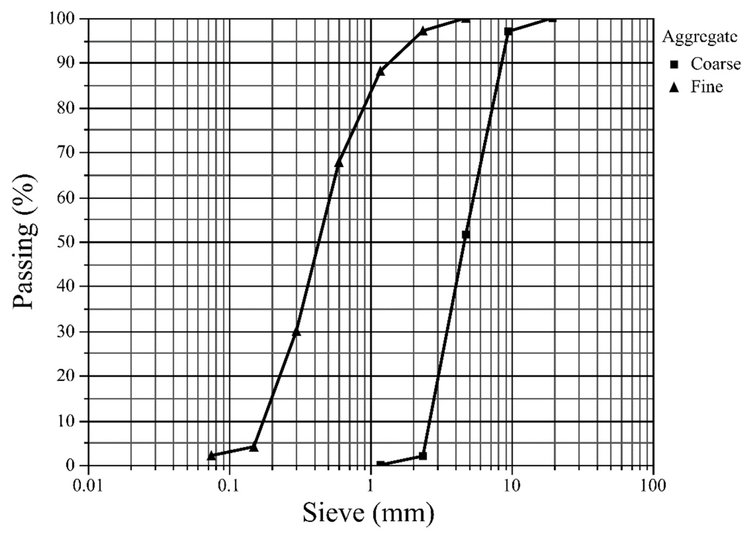
2.1.2. Aggregate
2.1.3. Activator
2.2. Mix Proportion
2.2.1. Conventional Concrete Mix
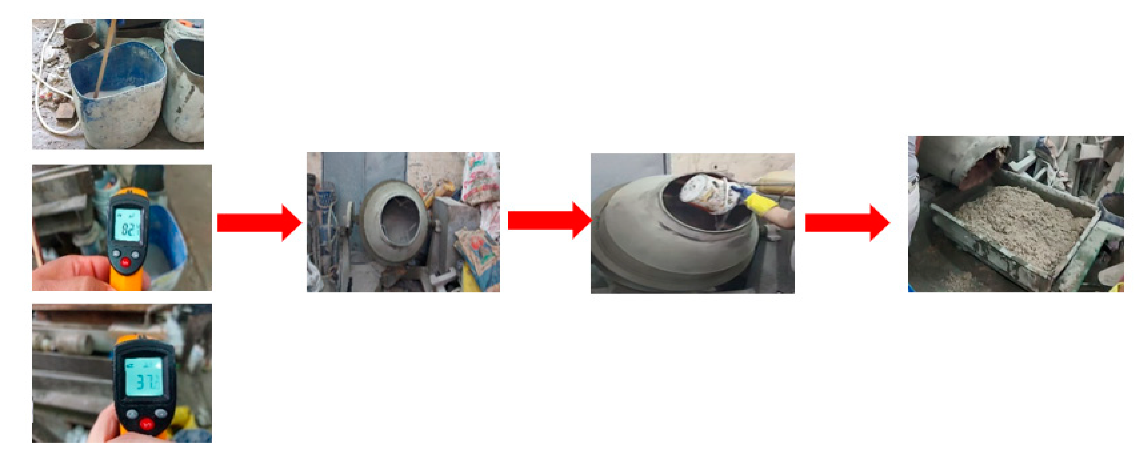
2.2.2. Geopolymer Concrete Mix
2.3. Mechanical Properties
2.3.1. Concrete
2.3.2. Reinforcing Steel
3. Experimental Plan
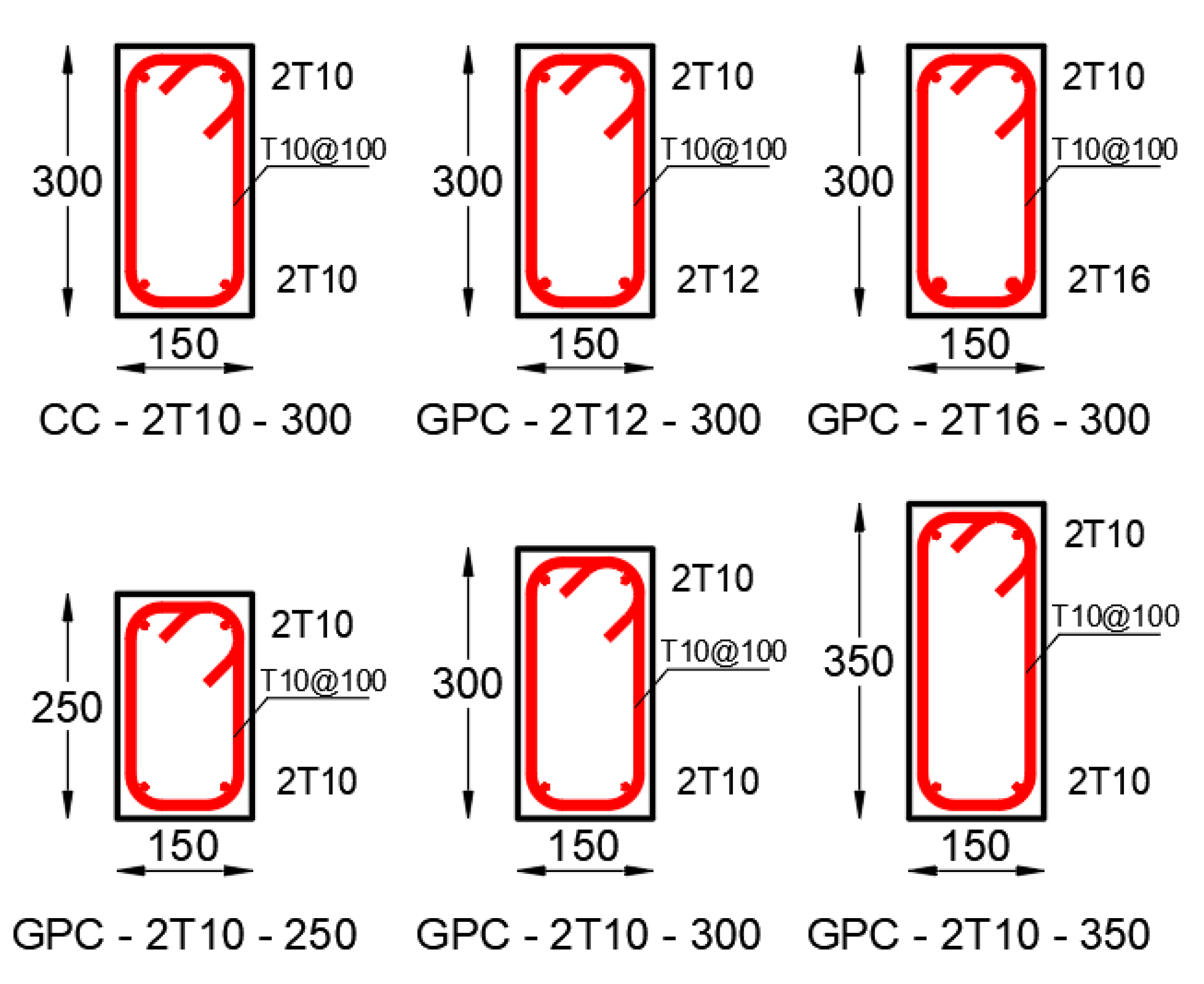
3.1. Details of the Test Specimens
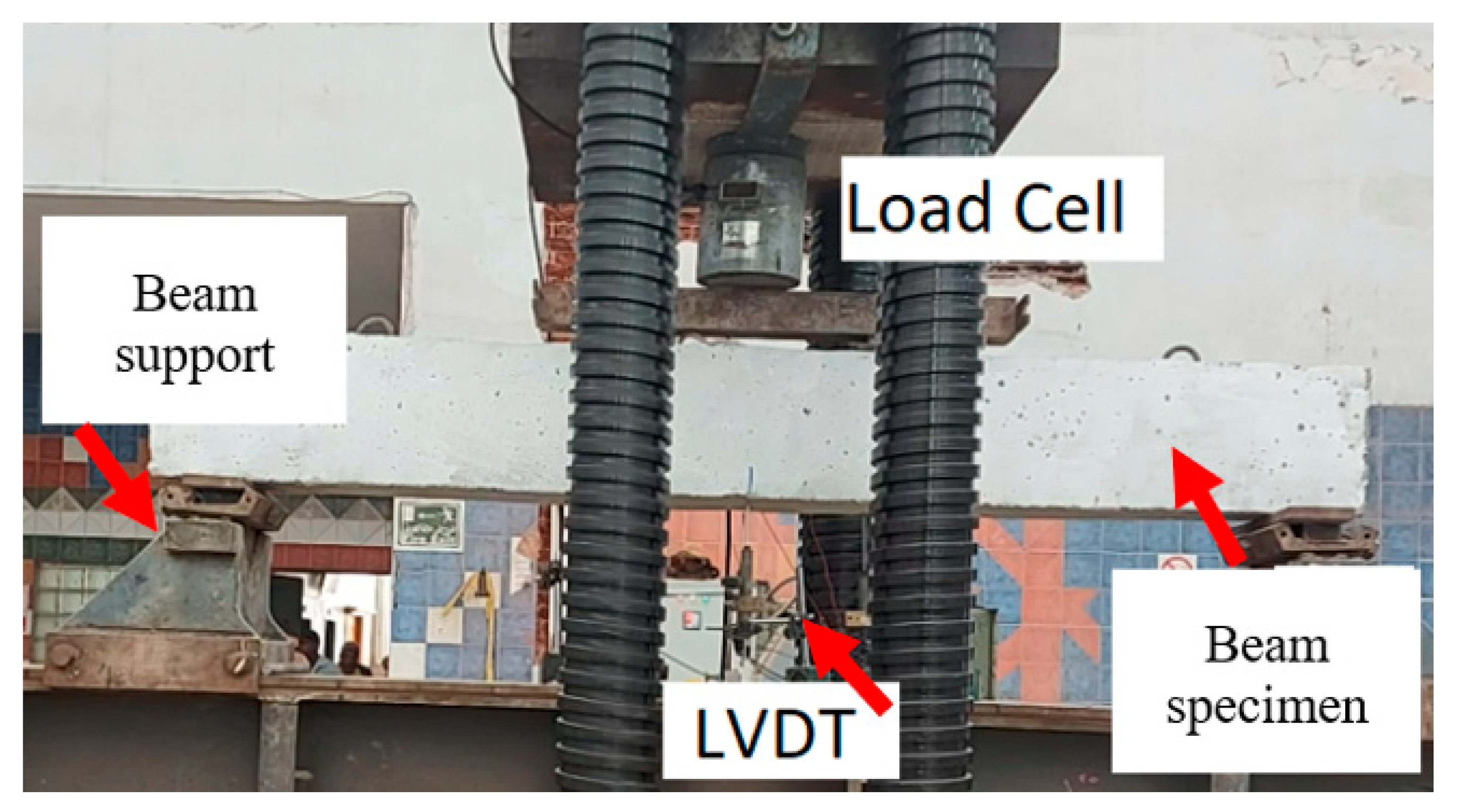
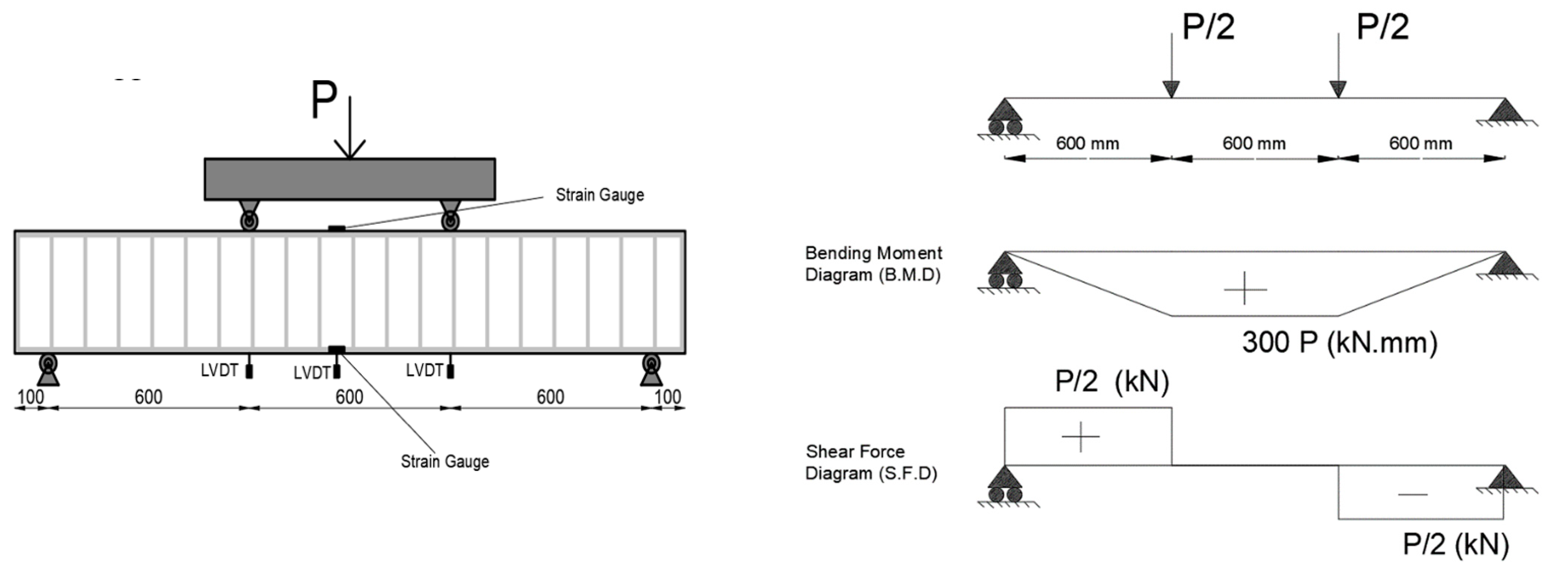
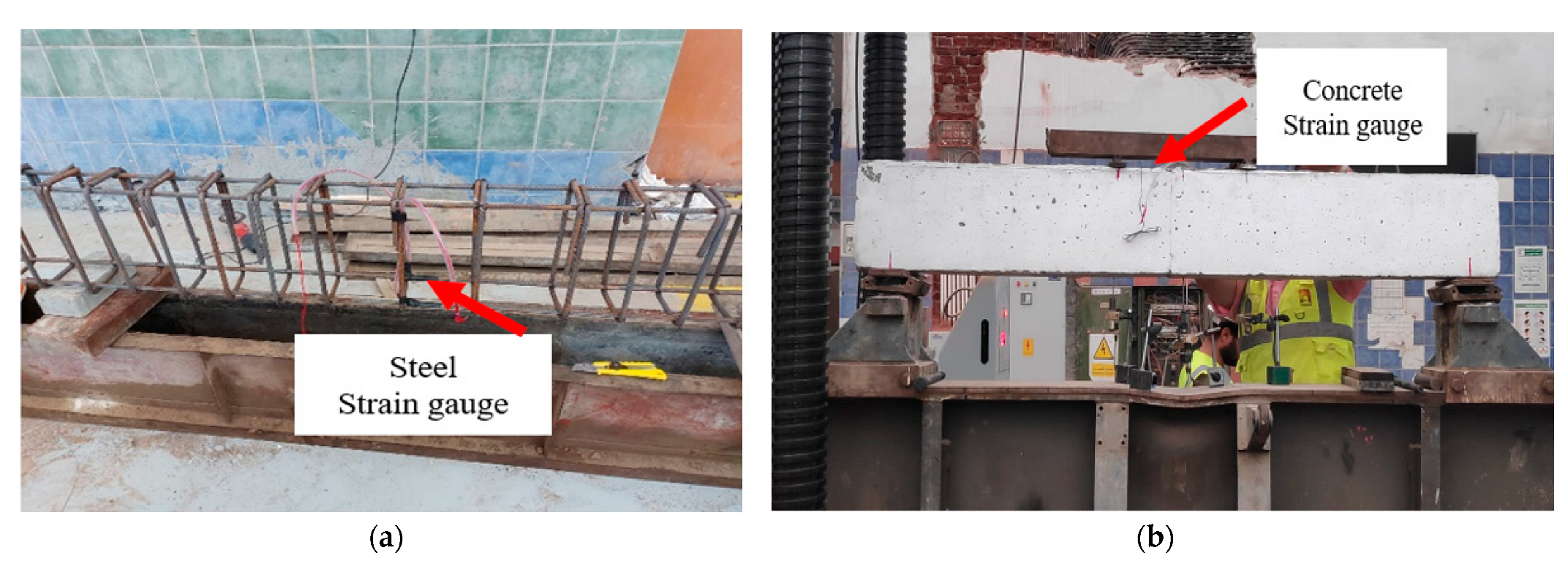
3.2. Test Setup and Procedure
4. Results and Discussion
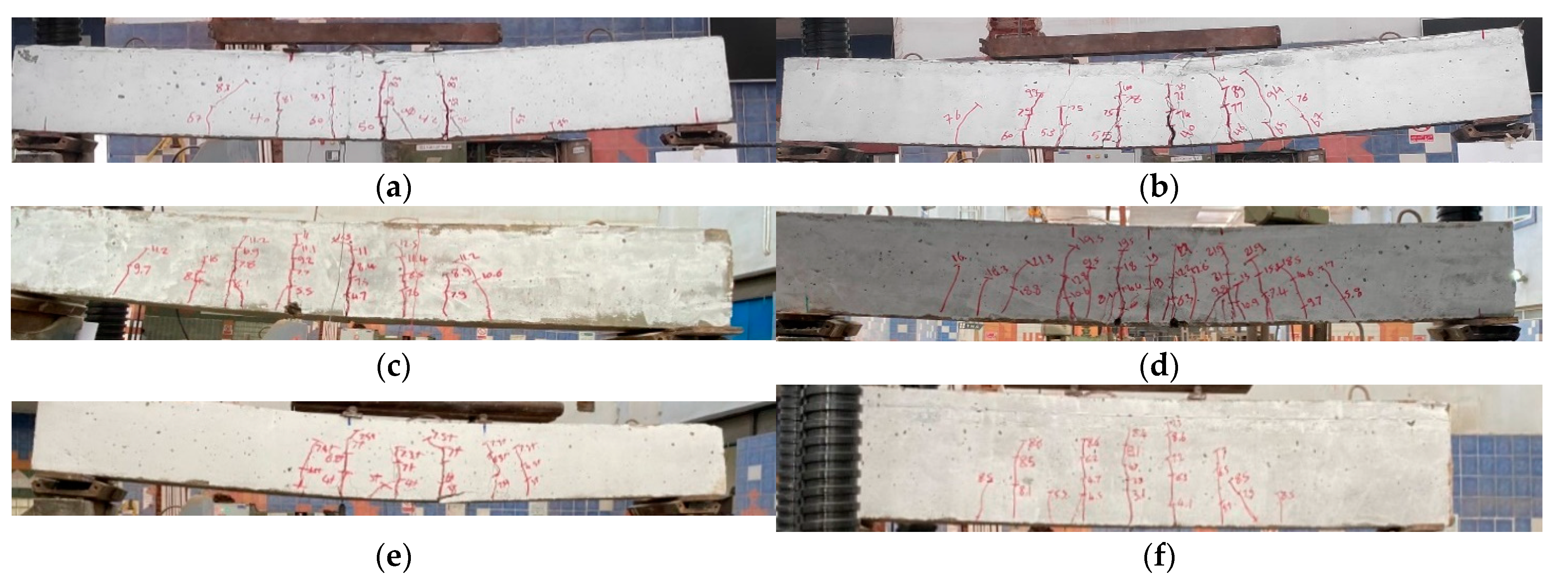
4.1. Cracks Distribution
- is the coefficient relating to average crack width and = 1.7,
- is the mean steel strain,
- is the mean crack spacing in mm.
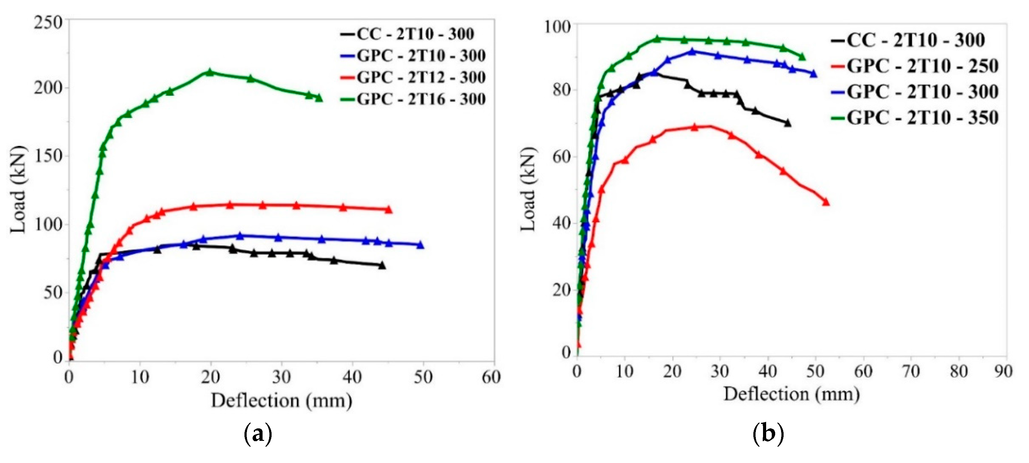
4.2. Load–Deflection Relationship
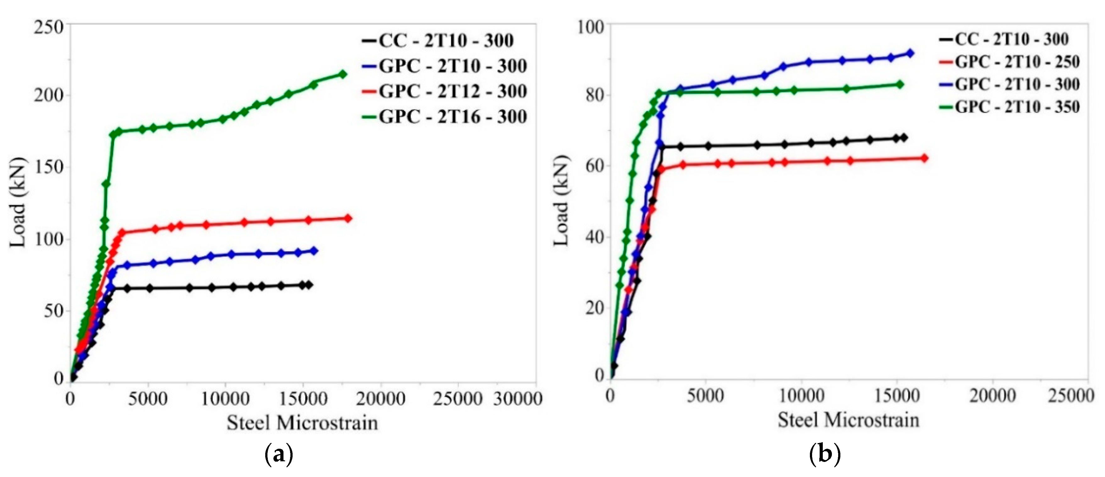
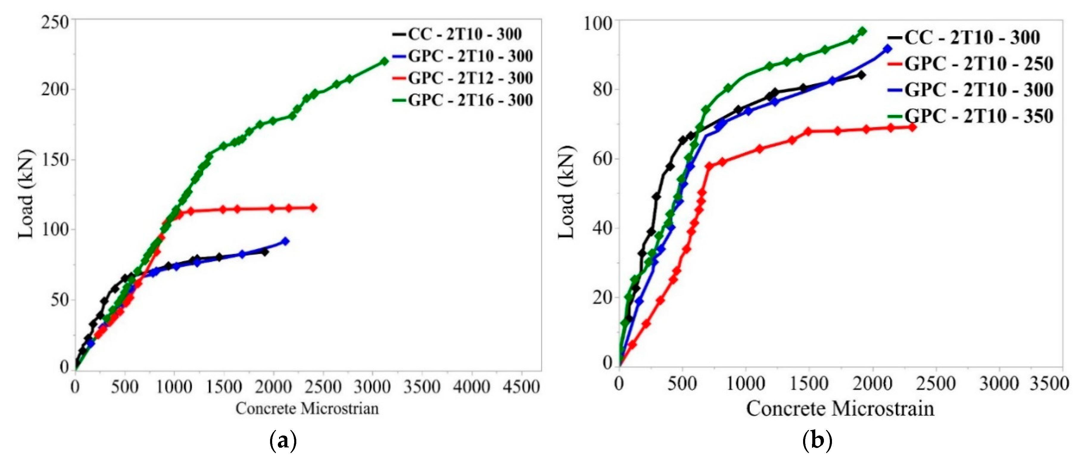
4.3. Strains in the Concrete and Steel Bars
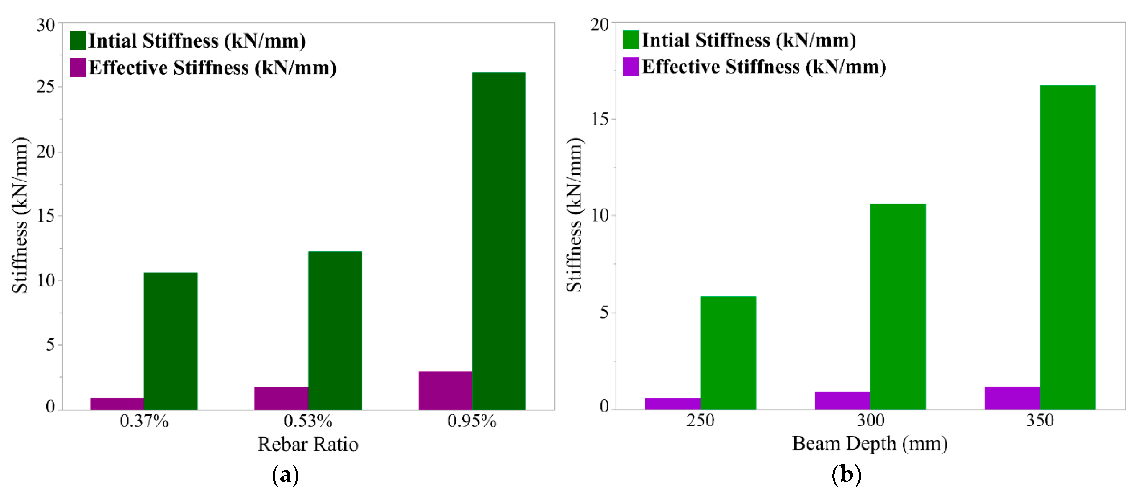
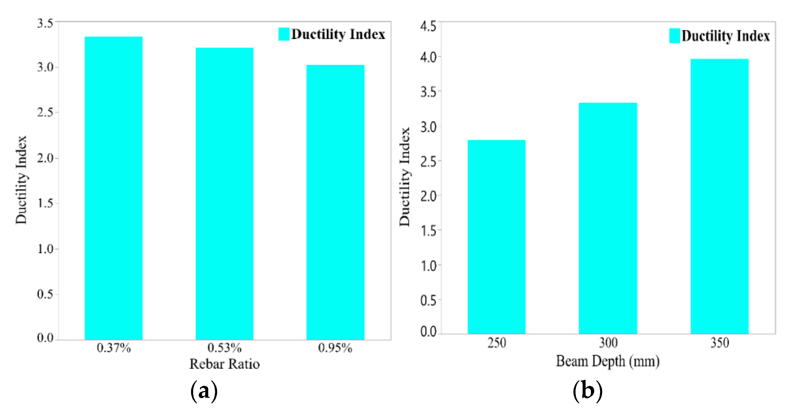
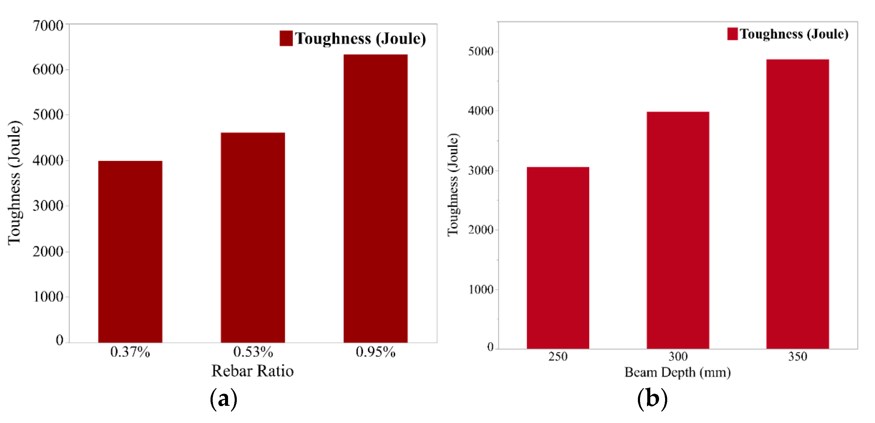
4.4. Stiffness, Ductility and Toughness
- K1 is the pre–yield “initial” stiffness in kN/mm,
- Py is the yielding load in kN,
- is the deflection at the yielding load in mm,
- K2 is the post–yield “effective” stiffness in kN/mm,
- Pu is the ultimate load in kN,
- is the deflection at the ultimate load in mm.
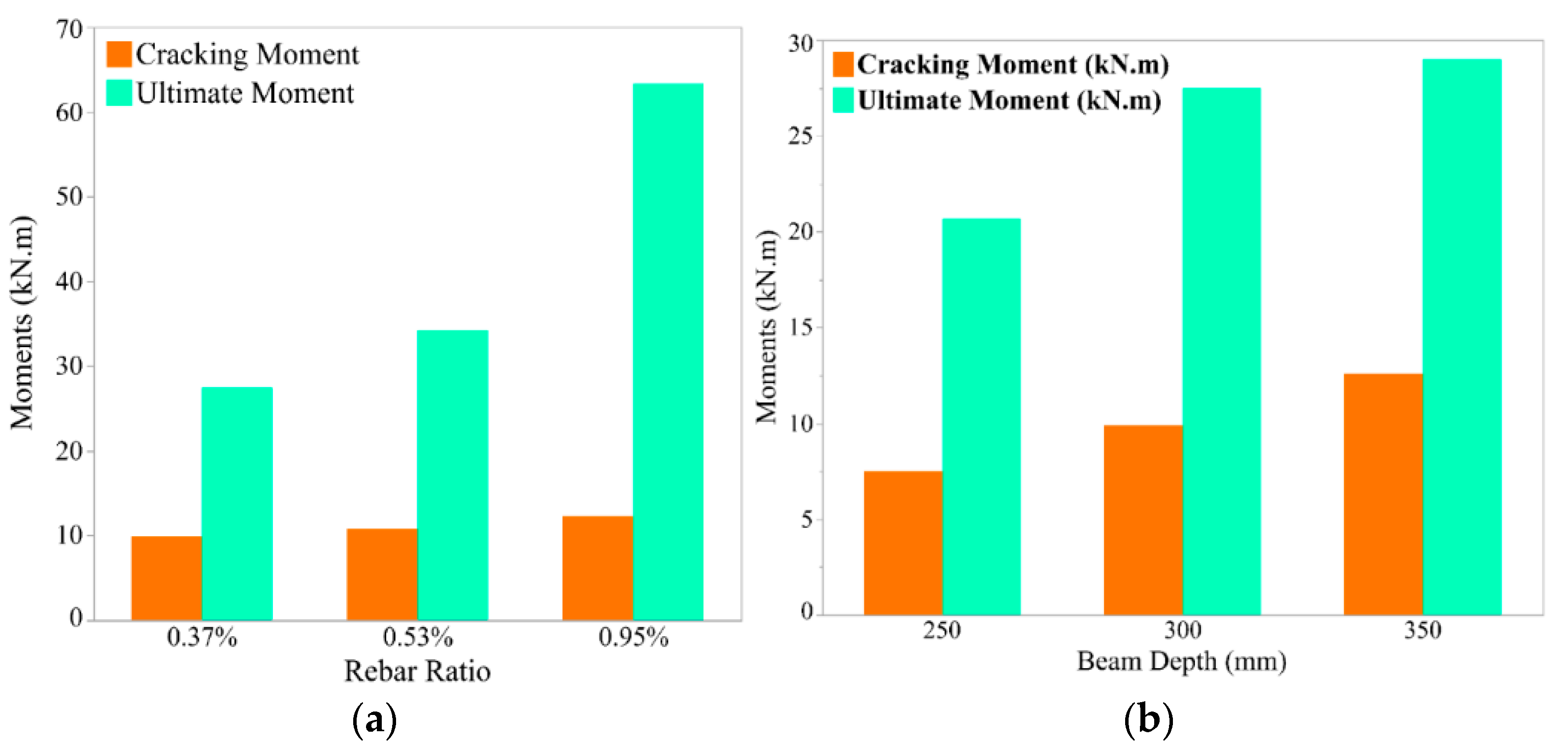
4.5. Cracking and Ultimate Moments
- Mcr is the theoretical cracking moment in kNm,
- fctr is the modulus of rupture of concrete in kN/m2,
- Ig is the gross moment of inertia of beam section in m4,
- yt is the distance from the tension side of beam to the neutral axis in m.
- Mu is the theoretical ultimate moment in kNm,
- fy is the steel yielding stress in MPa,
- As is the main steel area in mm2,
- d is the effective depth of beam in mm,
- a is the concrete compression zone depth in mm,
- b is the beam width in mm.
- Mn is the unfactored theoretical nominal moment in kNm,
- is the cylinder compressive strength of concrete in MPa,
- is the ratio of the depth of the equivalent stress block to the actual neutral axis depth.
5. Conclusions
- The load-carrying capacity of the GPC beams increased with increasing both the beam depth and rebar ratio. Compared to the CC beams, the flexural moment capacity of the reinforced GPC beams was 7.4% higher, and the cracking moment was 17.5% lower due to the lower modulus of rupture.
- The initial and effective stiffnesses of the GPC beams increased with increasing both the beam depth and rebar ratio. Compared to the CC beams, the initial and effective stiffnesses of the GPC beams were lower by 60%. Furthermore, the deflection of the GPC beams was 48.7% higher due to their lower modulus of elasticity.
- Increasing the beam depth significantly increases the beam ductility but using a higher rebar ratio decreases the beam ductility. However, the toughness of the GPC beams increased by increasing either beam depth or rebar ratio. Compared to the CC beams, the ductility of GPC beams was 28% lower, and the toughness was 18.3% higher.
- The crack distributions of the GPC beams occurred earlier, in more numbers and longer than those appearing in the CC beams. As the rebar ratio increased, the appearance of the cracks was retarded, and the average spacing of the developed cracks on the GPC beams decreased and the number of cracks increased. Increasing the GPC beam depth led to the delay in the occurrence of the cracks and the increase in the average spacing of the developed cracks.
- The Egyptian code of practice ECP203 and ACI318 should be applicable in predicting the flexural moment capacity of under-reinforced GPC beams.
6. Future Recommendations
Author Contributions
Funding
Institutional Review Board Statement
Informed Consent Statement
Data Availability Statement
Conflicts of Interest
References
- Van Deventer, J.S.J.; Provis, J.L.; Duxson, P. Technical and commercial progress in the adoption of geopolymer cement. Miner. Eng. 2012, 29, 89–104. [Google Scholar] [CrossRef]
- Luan, C.; Shi, X.; Zhang, K.; Utashev, N.; Yang, F.; Dai, J.; Wang, Q. A mix design method of fly ash geopolymer concrete based on factors analysis. Constr. Build. Mater. 2021, 272, 121612. [Google Scholar] [CrossRef]
- Ashour, A.Z.; Gallab, A.H.; Khafaga, M.A.; Rashad, A.; Kohail, M. Using metakaolin and ground granulated blast furnace slag in production of geopolimer concrete. J. Tianjin Univ. Sci. Technol. 2021, 54, 84–112. [Google Scholar] [CrossRef]
- Hadi, M.N.S.; Farhan, N.A.; Sheikh, M.N. Design of geopolymer concrete with GGBFS at ambient curing condition using Taguchi method. Constr. Build. Mater. 2017, 140, 424–431. [Google Scholar] [CrossRef]
- Amer, I.; Kohail, M.; El-Feky, M.S.; Rashad, A.; Khalaf, M.A. Characterization of alkali-activated hybrid slag/cement concrete. Ain Shams Eng. J. 2021, 12, 135–144. [Google Scholar] [CrossRef]
- Fernandez-Jimenez, A.M.; Palomo, A.; Lopez-Hombrados, C. Engineering properties of alkali-activated fly ash concrete. Mater. J. 2006, 103, 106–112. [Google Scholar] [CrossRef]
- Zhang, H.Y.; Kodur, V.; Wu, B.; Yan, J.; Yuan, Z.S. Effect of temperature on bond characteristics of geopolymer concrete. Constr. Build. Mater. 2018, 163, 277–285. [Google Scholar] [CrossRef]
- Amer, I.; Kohail, M.; El-Feky, M.S.; Rashad, A.; Khalaf, M.A. A review on alkali-activated slag concrete. Ain Shams Eng. J. 2021, 12, 1475–1499. [Google Scholar] [CrossRef]
- Aziz, I.H.; Abdullah, M.M.A.B.; Mohd Salleh, M.A.A.; Azimi, E.A.; Chaiprapa, J.; Sandu, A.V. Strength development of solely ground granulated blast furnace slag geopolymers. Constr. Build. Mater. 2020, 250, 118720. [Google Scholar] [CrossRef]
- Sumajouw, D.; Hardjito, D.; Wallah, S.E.; Rangan, B.V. Behaviour and strength of reinforced fly ash-based geopolymer concrete beams. Civ. Eng. Dimens. 2005, 6, 1020. [Google Scholar]
- Adak, D.; Sarkar, M.; Mandal, S. Structural performance of nano-silica modified fly-ash based geopolymer concrete. Constr. Build. Mater. 2017, 135, 430–439. [Google Scholar] [CrossRef]
- Ferdous, W.; Manalo, A.; Khennane, A.; Kayali, O. Geopolymer concrete-filled pultruded composite beams—Concrete mix design and application. Cem. Concr. Compos. 2015, 58, 1–13. [Google Scholar] [CrossRef]
- Du, Y.; Wang, J.; Shi, C.; Hwang, H.J.; Li, N. Flexural behavior of alkali-activated slag-based concrete beams. Eng. Struct. 2021, 229, 111644. [Google Scholar] [CrossRef]
- Moazzenchi, S.; Oskouei, A.V. A comparative experimental study on the flexural behavior of geopolymer concrete beams reinforced with FRP bars. J. Rehabil. Civ. Eng. 2023, 11, 21–42. [Google Scholar] [CrossRef]
- Zinkaah, O.H.; Alridha, Z.; Alhawat, M. Numerical and theoretical analysis of FRP reinforced geopolymer concrete beams. Case Stud. Constr. Mater. 2022, 16, e01052. [Google Scholar] [CrossRef]
- Kumar, P.U.; Bendapudi, S. Flexural behaviour of reinforced Geopolymer concrete beams with GGBS and metakaoline. Int. J. Civ. Eng. Technol. 2016, 7, 260–277. [Google Scholar]
- Hutagi, A.; Khadiranaikar, R.B. Flexural behavior of reinforced geopolymer concrete beams. Int. Conf. Electr. Electron. Optim. Tech. ICEEOT 2016, 2016, 3463–3467. [Google Scholar] [CrossRef]
- Vithiyaluxmi, V.B.; Senthamilselvi, P. Flexural behaviour of geopolymer reinforced concrete beam with partial replacement of coarse aggregate by using steel slag. Int. Res. J. Eng. Technol. 2021, 8. [Google Scholar]
- Ahmed, H.Q.; Jaf, D.K.; Yaseen, S.A. Flexural capacity and behaviour of geopolymer concrete beams reinforced with glass fibre-reinforced polymer bars. Int. J. Concr. Struct. Mater. 2020, 14, 1–16. [Google Scholar] [CrossRef]
- Kumaravel, D.; Thirugnanasambandam, S. Flexural behaviour of geopolymer concrete beams. Int. J. Adv. Eng. Res. Stud. 2013, 3, 2249–8974. [Google Scholar]
- Subramanian, N.; Solaiyan, E.; Sendrayaperumal, A.; Lakshmaiya, N. Flexural behaviour of geopolymer concrete beams reinforced with BFRP and GFRP polymer composites. Adv. Struct. Eng. 2022, 25, 954–965. [Google Scholar] [CrossRef]
- Maranan, G.B.; Manalo, A.C.; Benmokrane, B.; Karunasena, W.; Mendis, P.; Nguyen, T.Q. Flexural behavior of geopolymer-concrete beams longitudinally reinforced with GFRP and steel hybrid reinforcements. Eng. Struct. 2019, 182, 141–152. [Google Scholar] [CrossRef]
- Mo, K.H.; Alengaram, U.J.; Jumaat, M.Z. Structural performance of reinforced geopolymer concrete members: A review. Constr. Build. Mater. 2016, 120, 251–264. [Google Scholar] [CrossRef]
- De Azevedo, A.R.G.; Cruz, A.S.A.; Marvila, M.T.; De Oliveira, L.B.; Monteiro, S.N.; Vieira, C.M.F.; Fediuk, R.; Timokhin, R.; Vatin, N.; Daironas, M. Natural fibers as an alternative to synthetic fibers in reinforcement of geopolymer matrices: A comparative review. Polymers 2021, 13, 2493. [Google Scholar] [CrossRef]
- Yanou, R.N.; Kaze, R.C.; Adesina, A.; Nemaleu, J.G.D.; Jiofack, S.B.K.; Djobo, J.N.Y. Performance of laterite-based geopolymers reinforced with sugarcane bagasse fibers, Case stud. Constr. Mater. 2021, 15, e00762. [Google Scholar] [CrossRef]
- BS EN 197-1; Cement—Part 1 Composition, Specifications and Conformity Criteria for Common Cements; British Standards Institution (BSI): London, UK, 2011.
- BS EN 12390-1; Concrete—Part 1: Shape Dimensions and Other Requirements for Specimens and Moulds; British Standards Institution (BSI): London, UK, 2011.
- ASTM C293; Flexural Strength of Concrete (Using Simple Beam with Center-Point Loading; American Society for Testing and Materials (ASTM): West Conshohocken, PA, USA, 2002.
- ASTM C469/C469M-14; Standard Test Method for Static Modulus of Elasticity and Poisson’s Ratio of Concrete in Compression; American Society for Testing and Materials (ASTM) International: West Conshohocken, PA, USA, 2014.
- ASTM C143/C143M; Standard Test Method for Slump of Hydraulic Cement Concrete; American Society for Testing and Materials (ASTM): West Conshohocken, PA, USA, 2015; pp. 1–4.
- Antony, J.C.; Saravanan, G.; Salahuddin, M.; Thirugnanasambandam, S. Development of fly ash based geopolymer precast concrete elements. Asian J. Civ. Eng. 2013, 14, 605–615. [Google Scholar]
- ECP Committee. ECP 203 Egyptian Code for Design and Construction of Concrete Structures (ECP 203-2020), 5th ed.; Housing and Building National Research Center: Cairo, Egypt, 2020. [Google Scholar]
- Ren, J.; Chen, H.; Sun, T.; Song, H.; Wang, M. Flexural behaviour of combined FA/GGBFS geopolymer concrete beams after exposure to elevated temperatures. Adv. Mater. Sci. Eng. 2017. [Google Scholar] [CrossRef]
- Yost, J.R.; Radlińska, A.; Ernst, S.; Salera, M.; Martignetti, N.J. Structural behavior of alkali activated fly ash concrete. Part.Structural testing and experimental findings. Mater. Struct. Constr. 2013, 46, 449–462. [Google Scholar] [CrossRef]
- Köksal, F.; Rao, K.S.; Babayev, Z.; Kaya, M. Effect of steel fibres on flexural toughness of concrete and RC beams. Arab. J. Sci. Eng. 2022, 47, 4375–4384. [Google Scholar] [CrossRef]
- ACI 318; Building Code Requirements for Structural Concrete (ACI 318-19) and Commentary (ACI 318R-19); The American Concrete Institute (ACI): Farmington Hills, MI, USA, 2019.


| Component | SiO2 | Al2O3 | Fe2O3 | Na2O | CaO | MgO | K2O | SO3 | TiO2 | Mn2O3 |
|---|---|---|---|---|---|---|---|---|---|---|
| GGBFS | 35.41 | 17.42 | 1.39 | 0.49 | 36.87 | 6.83 | 0.97 | - | 0.11 | 0.35 |
| OPC | 21.07 | 5.01 | 3.47 | 0.29 | 63.25 | 2.52 | 0.19 | 3.05 | - | - |
| GGBFS | OPC | C. Agg. * | F. Agg. ** | NaOH | Na2SiO3 | Water | Superplastizer *** | |
|---|---|---|---|---|---|---|---|---|
| Conventional | - | 450 | 1058 | 710 | - | - | 176 | 12.2 |
| Slag Concrete by Amer et al. [5] | 450 | - | 1093 | 547 | 41 | 131 | 112 | - |
| Property | GPC | CC |
|---|---|---|
| Compressive strength fcu (MPa) | 51.62 | 45.36 |
| Modulus of rupture fctr (MPa) | 4.38 | 5.46 |
| Modulus of elasticity Ec (GPa) | 25.10 | 32.30 |
| 10 mm Diameter (T10) | 12 mm Diameter (T12) | 16 mm Diameter (T16) | |
|---|---|---|---|
| Yield stress (MPa) | 542.30 | 519.60 | 558.40 |
| Ultimate stress (MPa) | 705.10 | 680.60 | 779.20 |
| Young's modulus (GPa) | 231.20 | 246.20 | 248.60 |
| Beam Label * | Bottom Reinforcement | Reinforcement Ratio, ρ | Total Depth (mm), t |
|---|---|---|---|
| CC-2T10-300 | 2T10 | 0.37% | 300 |
| GPC-2T10-300 | 2T10 | 0.37% | 300 |
| GPC-2T12-300 | 2T12 | 0.53% | 300 |
| GPC-2T16-300 | 2T16 | 0.95% | 300 |
| GPC-2T10-250 | 2T10 | 0.45% | 250 |
| GPC-2T10-350 | 2T10 | 0.31% | 350 |
| Specimens | Flexural Cracks | Shear Cracks | Crack Width (mm) |
|---|---|---|---|
| CC-2T10-300 | 5 | 1 | 0.23 |
| GPC-2T10-300 | 7 | 1 | 0.26 |
| GPC-2T12-300 | 9 | 2 | 0.24 |
| GPC-2T16-300 | 12 | 5 | 0.22 |
| GPC-2T10-250 | 6 | - | 0.27 |
| GPC-2T10-350 | 9 | 1 | 0.21 |
| Specimens | Py (kN) | Pu (kN) | K1 (kN/mm) | K2 (kN/mm) | Toughness (Joule) | |||
|---|---|---|---|---|---|---|---|---|
| CC-2T10-300 | 66.5 | 85.3 | 3.8 | 16.2 | 17.50 | 1.52 | 4.26 | 3368 |
| GPC-2T10-300 | 76.6 | 91.6 | 7.23 | 24.1 | 10.59 | 0.89 | 3.33 | 3985 |
| GPC-2T12-300 | 86.6 | 114.0 | 7.08 | 22.7 | 12.23 | 1.75 | 3.21 | 4605 |
| GPC-2T16-300 | 172.0 | 211.0 | 6.58 | 19.9 | 26.14 | 2.93 | 3.02 | 6320 |
| GPC-2T10-250 | 58.9 | 69.02 | 10.12 | 28.2 | 5.83 | 0.56 | 2.79 | 3055 |
| GPC-2T10-350 | 80.3 | 96.7 | 4.8 | 19.03 | 16.73 | 1.15 | 3.96 | 4865 |
| Specimens | Mcr (kNm) | Mu (kNm) by ECP203 | Mn (kNm) by ACI318 | |||||
|---|---|---|---|---|---|---|---|---|
| Mexp | Mtheo | Mexp/Mtheo | Mexp | Mtheo | Mexp/Mtheo | Mtheo | Mexp/Mtheo | |
| CC-2T10-300 | 12.0 | 14.2 | 0.85 | 25.59 | 23.47 | 1.09 | 23.48 | 1.09 |
| GPC-2T10-300 | 9.9 | 11.4 | 0.87 | 27.48 | 23.56 | 1.17 | 23.58 | 1.17 |
| GPC-2T12-300 | 10.8 | 11.8 | 0.92 | 34.2 | 32.01 | 1.07 | 32.16 | 1.06 |
| GPC-2T16-300 | 12.3 | 12.9 | 0.95 | 63.3 | 58.42 | 1.08 | 59.19 | 1.07 |
| GPC-2T10-250 | 7.5 | 8.0 | 0.93 | 20.7 | 19.31 | 1.07 | 19.32 | 1.07 |
| GPC-2T10-350 | 12.6 | 15.2 | 0.83 | 29.01 | 27.82 | 1.04 | 27.83 | 1.04 |
Publisher’s Note: MDPI stays neutral with regard to jurisdictional claims in published maps and institutional affiliations. |
© 2022 by the authors. Licensee MDPI, Basel, Switzerland. This article is an open access article distributed under the terms and conditions of the Creative Commons Attribution (CC BY) license (https://creativecommons.org/licenses/by/4.0/).
Share and Cite
Mamdouh, H.; Ali, A.M.; Osman, M.A.; Deifalla, A.F.; Ayash, N.M. Effects of Size and Flexural Reinforcement Ratio on Ambient-Cured Geopolymer Slag Concrete Beams under Four-Point Bending. Buildings 2022, 12, 1554. https://doi.org/10.3390/buildings12101554
Mamdouh H, Ali AM, Osman MA, Deifalla AF, Ayash NM. Effects of Size and Flexural Reinforcement Ratio on Ambient-Cured Geopolymer Slag Concrete Beams under Four-Point Bending. Buildings. 2022; 12(10):1554. https://doi.org/10.3390/buildings12101554
Chicago/Turabian StyleMamdouh, Hala, Ashraf M. Ali, Mostafa A. Osman, Ahmed F. Deifalla, and Nehal M. Ayash. 2022. "Effects of Size and Flexural Reinforcement Ratio on Ambient-Cured Geopolymer Slag Concrete Beams under Four-Point Bending" Buildings 12, no. 10: 1554. https://doi.org/10.3390/buildings12101554