1. Introduction
Buildings in earthquake-prone areas are substantially different from those in less seismically active regions. Their most important distinctive features include the ability to absorb seismic impacts (some of which are very strong in certain cases), their addition to regular loads, and the ability to maintain the pre-set bearing capacity. Plastic deformations in the elements of the bearing system are acceptable for most buildings exposed to seismic impacts. Acceptable plastic deformations are specified in national codes, and sample requirements set by these national codes are provided in [
1].
Principles of analysis and design of bearing systems for earthquake-resistant buildings featuring a pre-set level of plastic deformations were developed more than half a century ago [
2] and they have served as the basis for most national codes that set the standards for the construction of earthquake-resistant buildings. The universal characteristic of a structure, or the plasticity coefficient (
), is the basis for standardizing the bearing capacity of structures of earthquake-resistant buildings, featuring a pre-set extent of plastic deformations.
The value of the plasticity coefficient is identified using various methods [
3,
4,
5,
6,
7,
8,
9], based on versatile parameters, such as the curvature of a reinforced concrete section, the plastic rotation angle of a reinforced concrete section, accumulation of damages, reduction of stiffness, among others.
The most widely used method of identifying the plasticity coefficient [
10] is theoretically and experimentally validated. It is applicable to a wide range of structures. Pursuant to this method, the plasticity coefficient (
) is defined as the ratio of the total acceptable deformation (
) to the value of the elastic phase of deformation (
):
Acceptable values of the plasticity coefficient are determined based on the results of experimental studies: conducted to learn more about the deformation of structures subjected to the entire range of loads, including the load at failure. Moreover, the most valuable results can be obtained under multi-cyclic loading, which reliably imitates seismic effects [
11,
12].
Authors of versatile publications [
3,
4,
5,
6,
7,
8,
9,
10] suggest that plasticity coefficients convey the features of failure mechanisms, specific to the principal types of bearing structures of buildings (reaching the limit state), and the failure mechanisms determine the boundary values of plasticity coefficients varying from 1.0 (brittle failure) to 6.0–8.0 (plastic failure).
Within the framework of the concept of the acceptable extent of plastic deformations of bearing structures of buildings determined by the coefficient of plasticity (
), the authors of the work [
2] proposed and validated a method for analyzing bearing systems, based on the principle of change (as a rule, by means of reduction) of the seismic load using the reduction factor (
), whose value is a function of the plasticity coefficient:
The authors of [
13,
14,
15,
16] have found that the value of the reduction factor, used to analyze various structures, depends on how implementable the plastic phase of deformation in these structures under seismic loads is. The reduction factor is equal to 1.0 for the elastic-brittle failure mechanism. The reduction factor may reach 0.12 for the elastoplastic failure mechanism that encompasses a pronounced plastic phase.
It should be emphasized that the method proposed in [
2] is based on the implementation of the elastoplastic mechanism of structural failure. However, the practical study of the failure of structures and structural materials under increasing static, dynamic, and multi-cyclic loads have demonstrated other types of failure mechanisms, such as the elastic-brittle failure, as well as various combinations of failure mechanisms triggered by the loading of bearing systems. A detailed analysis of the effect of failure mechanisms on the evolution of the characteristic of the reduction factor is presented in [
17].
More studies on earthquake-resistant bearing structures and bearing systems have been published [
18,
19,
20] and their findings are relevant and sought-after. It is noteworthy that the studies focused on determining plasticity coefficients and corresponding reduction factors have been more frequently conducted for traditional types of bearing structures, which have long been used in the bearing systems of earthquake-resistant buildings, including reinforced concrete structures, masonry, steel, wood, and other widely used types of structures. However, the construction industry has been generating new types of building structures and structural members, whose seismic resistance and mechanical characteristics under dynamic loading have not been studied. These new types of structural elements include anchors.
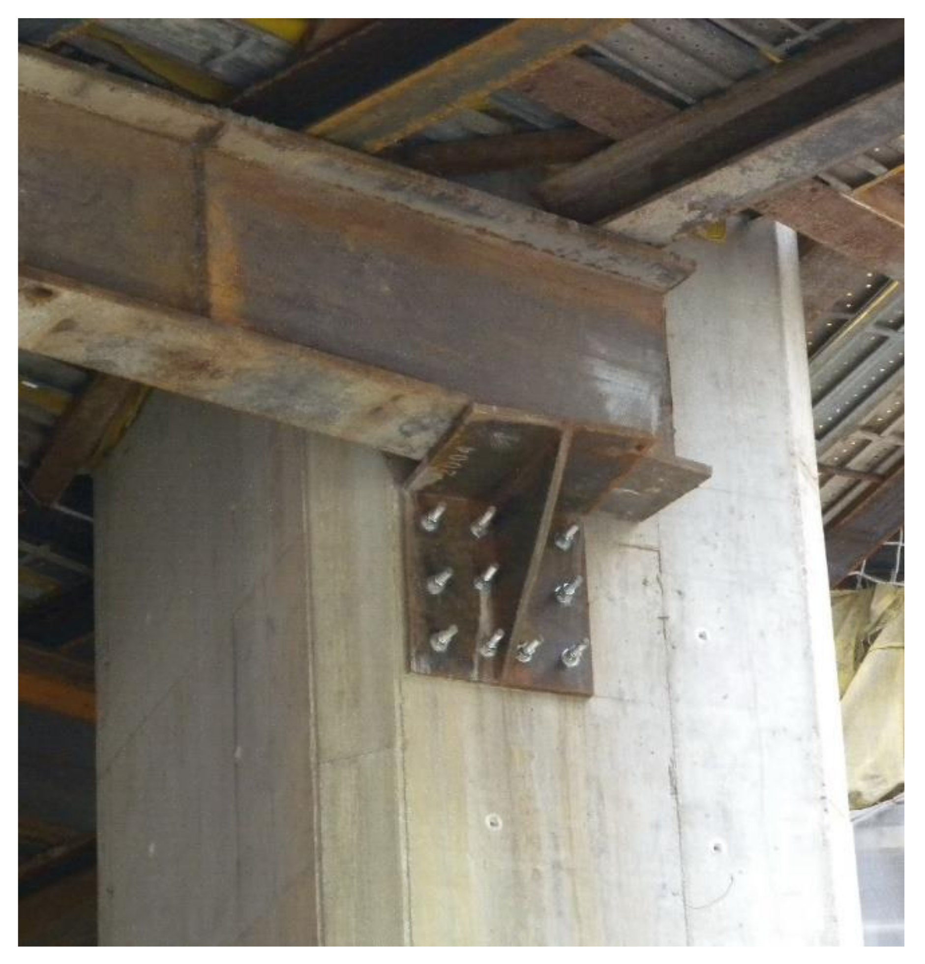
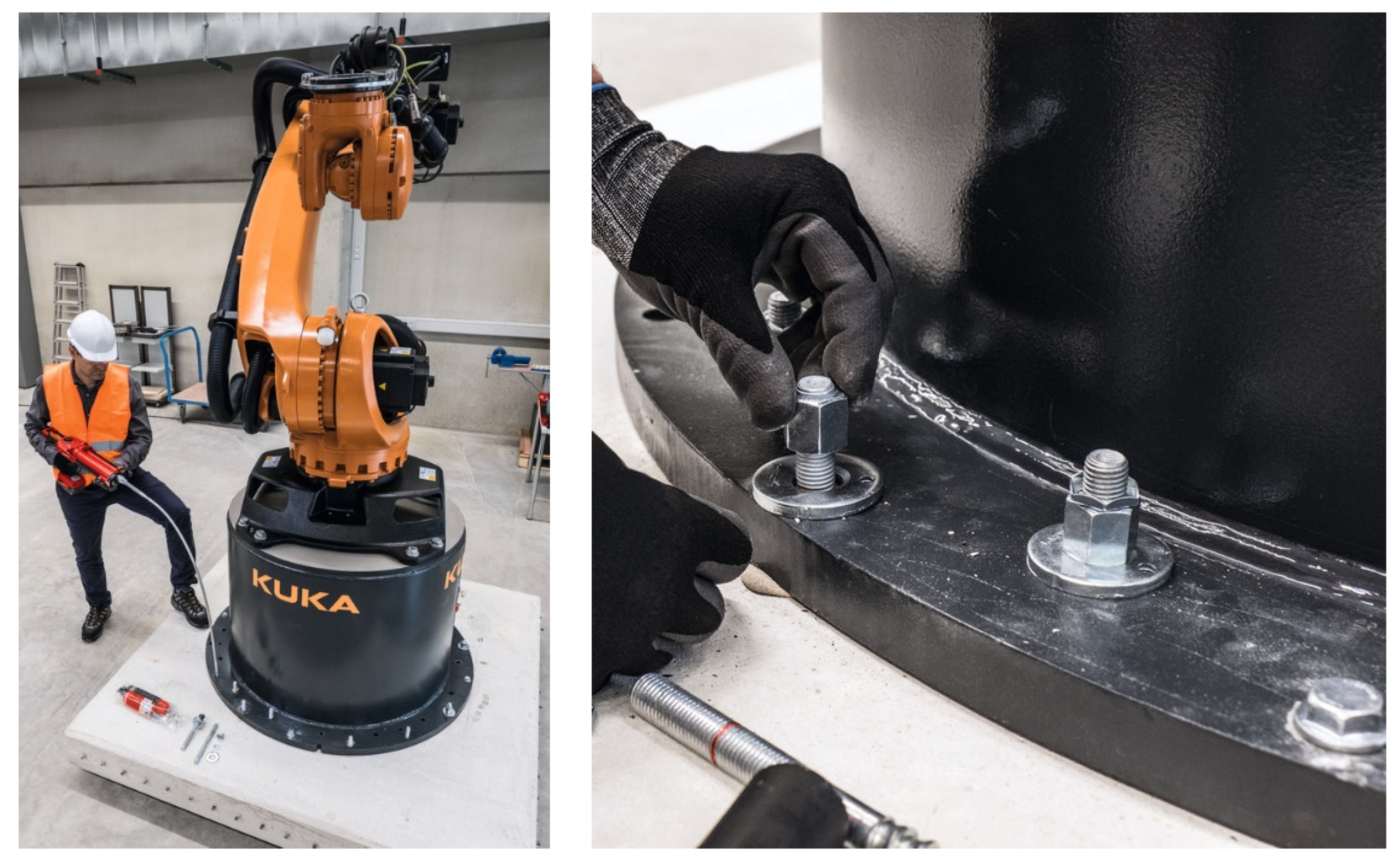
Anchors are structural elements that are most often used to fasten other structures and equipment to a reinforced concrete (concrete) base. Anchors fasten a wide range of structures and products, ranging from individual structural members, that are part of a building’s bearing system (
Figure 1), to various types of engineering equipment, including pipelines and control panels (
Figure 2), and non-bearing elements of buildings, such as suspended facades, partitions, translucent structures, and other items.
The most important feature of anchors is their integration into structures. There are several basic types of anchorages used to fasten items to concrete (reinforced concrete) bases:
- -
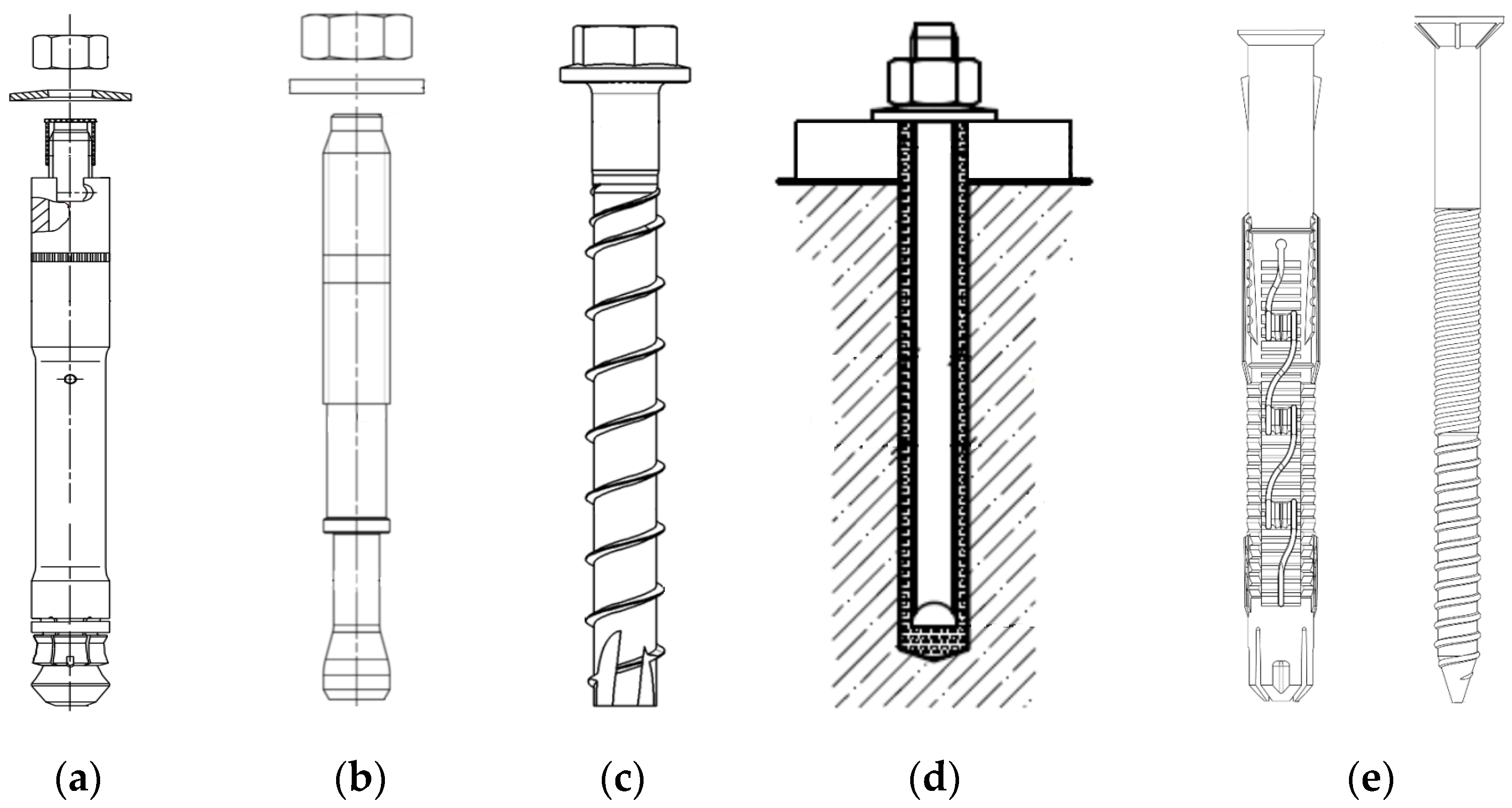
post-installed anchors, such as mechanical anchors (wedge expansion anchors, undercut anchors, screw anchors, push-in anchors, etc.); adhesive anchors (epoxy resin, polyurethane, and polyester anchors with quartz sand and cement mixtures added), and plastic anchors (plastic dowels and plate anchors) (
Figure 3).
- -
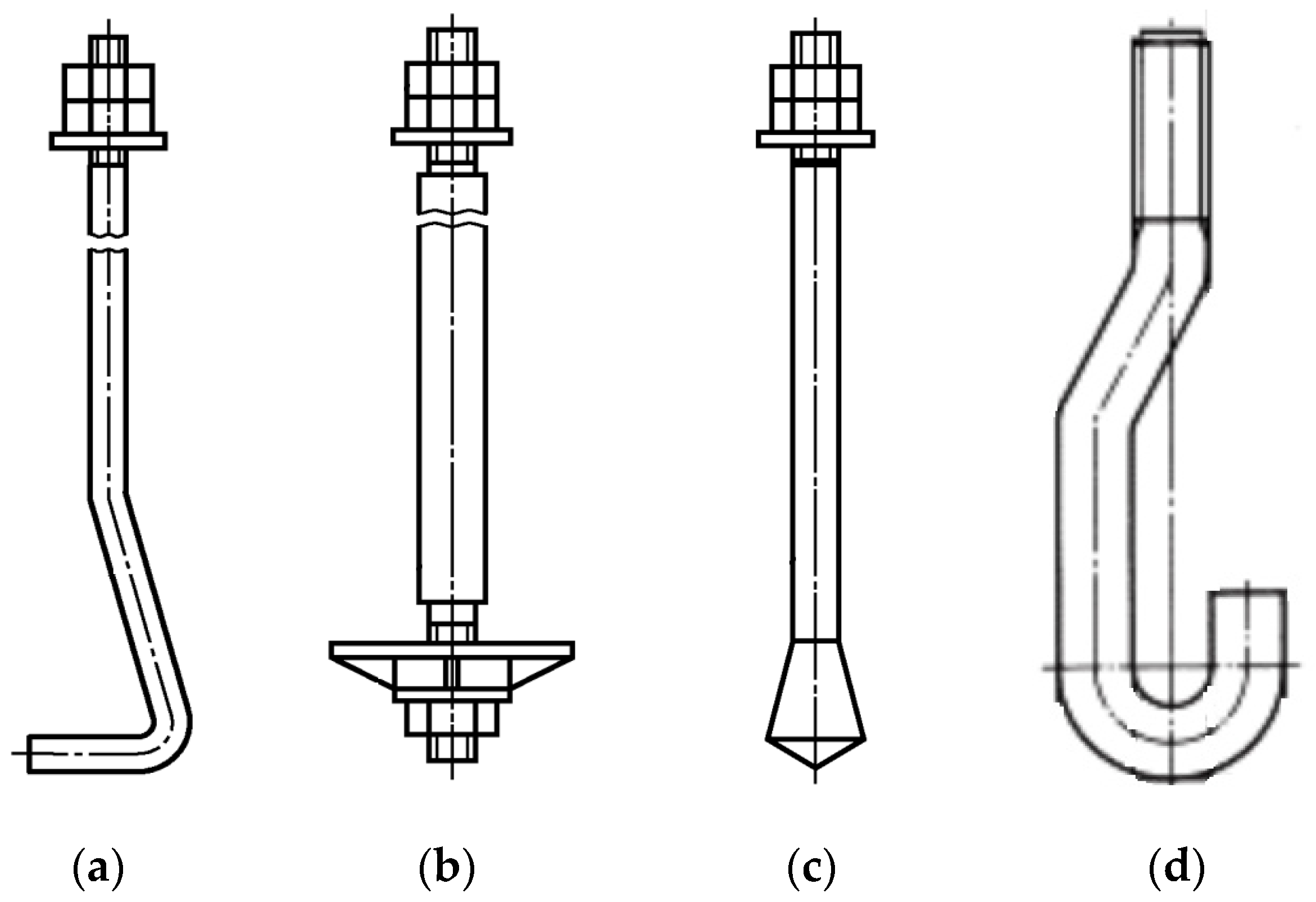
anchors, installed in the base in the process of its concreting (bent anchors, anchors with an anchor plate, anchors with a conical end, anchors with a bar hook, compound anchors, etc.) (
Figure 4).
The mechanical properties of expansion anchors [
21,
22], undercut anchors, screw anchors, and chemical anchors [
23] subjected to static loads in standard construction environments have been adequately studied. The studies of anchors, subjected to dynamic loads, and cyclic crack opening conditions are presented in [
24,
25]. According to [
22], if anchors embedded in a concrete base are subjected to static loads the following failure mechanisms are triggered:
- -
the anchor material failure;
- -
the base material failure (concrete cone breakout or splitting);
- -
the failure of the interface between the anchor and the base (anchor slippage) for mechanical anchors;
- -
the failure of the interface between the adhesive composition and the base (anchor slippage) for adhesive anchors.
However, according to the results of these studies, the most important characteristics of the anchor behaviour under seismic or equivalent loading (multi-cyclic dynamic loading) needed to forecast the anchor behaviour under seismic loading, have not been determined. These characteristics include failure mechanisms and correlations between the total and elastic deformation under loading. Moreover, the effect of the earthquake-damaged base on the bearing capacity of anchors has not been identified.
The current state of the problem of prognosticating the reliability of anchorages in buildings under seismic loads necessitates the resolution of the above-mentioned major problems, which are determined by the requirements applicable to such structural elements under seismic loads and their behaviour as parts of building structures.
One of the most important tasks is to study the effect produced by the earthquake-damaged base on the bearing capacity of anchors. As shown above, a traditional approach to designing earthquake-resistant buildings assumes the occurrence of the plastic deformation phase, which in the case of a concrete (reinforced concrete) base is manifested as a system of cracks having different-sized openings. The most conservative case is cracking at the point of anchoring. The probability of cracks passing through the point of anchoring is proven in several studies [
11,
12,
26,
27,
28]. According to [
11], the width of post-earthquake residual crack openings in columns and beams having different cross-sections varied from 0.26 to 1.04 mm. Other works [
1] show that national codes have set requirements for the maximum acceptable crack opening width in structures, including in reinforced concrete structures, when cracking occurs due to the plastic deformations triggered by seismic loads. These requirements are viewed as the objectives pursued in the process of designing buildings that may be subjected to earthquake loadings of different intensity. Design objectives that entail small crack openings are standardized for a building subjected to low-intensity earthquake loadings (which may occur quite often). In several national codes (e.g., [
29]), the post-earthquake condition of structures is called the Immediate Occupancy Level (IOL), and the limit crack opening width must not exceed 1.5 mm. In case of a building subjected to high-intensity earthquake loadings (which rarely occur), standardized design objectives entail substantially wider crack openings. This post-earthquake state of structures is called the Life Safety Level (LSL), and the limit crack opening width must not exceed 3.0 mm. Other values of parameters describing the acceptable level of plastic deformations under seismic loading may also be established.
It is obvious that anchorages embedded in earthquake-damaged bases may have the bearing capacity characteristics that differ significantly from the bearing capacity characteristics typical for regular operating conditions. However, at present there is no information about the anchor behaviour in a damaged concrete (reinforced concrete) base or the implementability of the plastic phase of deformation in this case.
Therefore, no studies conducted so far have generated any results that open the way to the application of general principles of seismic design to anchorages. These principles are based on the analysis of acceptable plastic deformations of an earthquake-damaged base. The proposed methods of seismic design of anchorages (for example, [
30]) do not comply with the universally accepted approaches to the design of earthquake resistant structures, which are based on the principle of acceptance of inelastic deformations. Given the state of the problem, the research pursues the following objectives:
experimental determination of failure mechanisms for the most frequently used types of anchors embedded in the concrete bases, whose cracks, caused by static and dynamic loading, are 0.8 and 1.5 mm wide;
determination of anchorage plasticity coefficients, corresponding to experimentally identified failure mechanisms.
The research findings can be used to determine seismic load reduction factors to be further applied in the seismic design of anchorages.
2. Materials and Methods
The research plan encompasses an experimental study of anchors embedded in a concrete base with a crack at the point of the anchor embedment. The crack opening width is assumed to be 0.8 and 1.5 mm, which corresponds to the research results [
1,
11] and the condition of the concrete base, known as the Immediate Occupancy Level (IOL). The condition of the structure of the concrete base, known as the Life Safety Level (LSL), which entails the crack opening width of 3.0 mm, will be studied at the next stage of the research project.
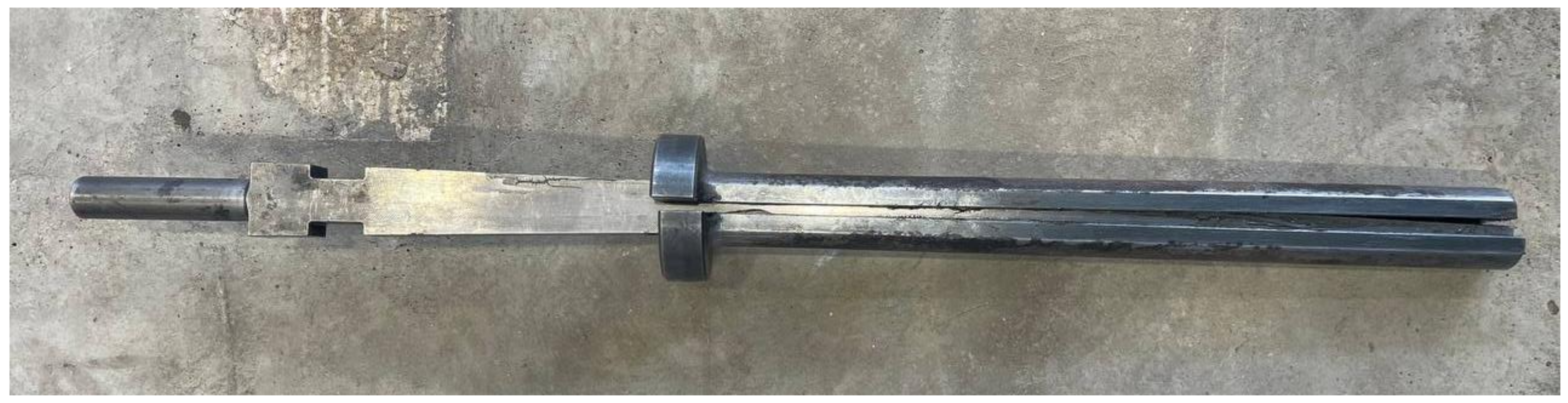
Specially designed wedge-shaped steel elements were used to make a crack having a pre-set opening width (
Figure 5). Dial gauge displacement indicators with the division value of 0.01 mm were used to control the crack opening width.
The studies were conducted for the types of anchors listed in
Table 1.
Concrete blocks, having C25/30 and C30/37 compressive strength classes, were used as the base for the embedment of anchors. Dimensions of the concrete blocks were determined by the anchor embedment depth and the anchorage diameter to prevent any obstacles to the concrete cone breakout in the process of the concrete failure. The blocks, designated for crack testing, had structural reinforcement to prevent the concrete base failure during cracking.
Cast-in-place anchors (bent anchor bolts and bolts with anchor plates) were embedded in the large holes that had been made in prefabricated base blocks. Cast-in-place anchors with bar hooks were embedded in the holes made during the concreting of the base blocks. After the embedment of anchors, the holes were filled with C40/50 fine-grained expanding concrete, whose expansion rate is 0.06–0.08 mm/m in unrestricted conditions.
Post-installed anchors were embedded in the holes that had been drilled in prefabricated base blocks. The parameters of a hole (the diameter and depth) complied with the manufacturer’s recommendations and were presented in
Table 1. The anchor nut was tightened using a torque wrench with the value of the tightening torque specified by the manufacturer.
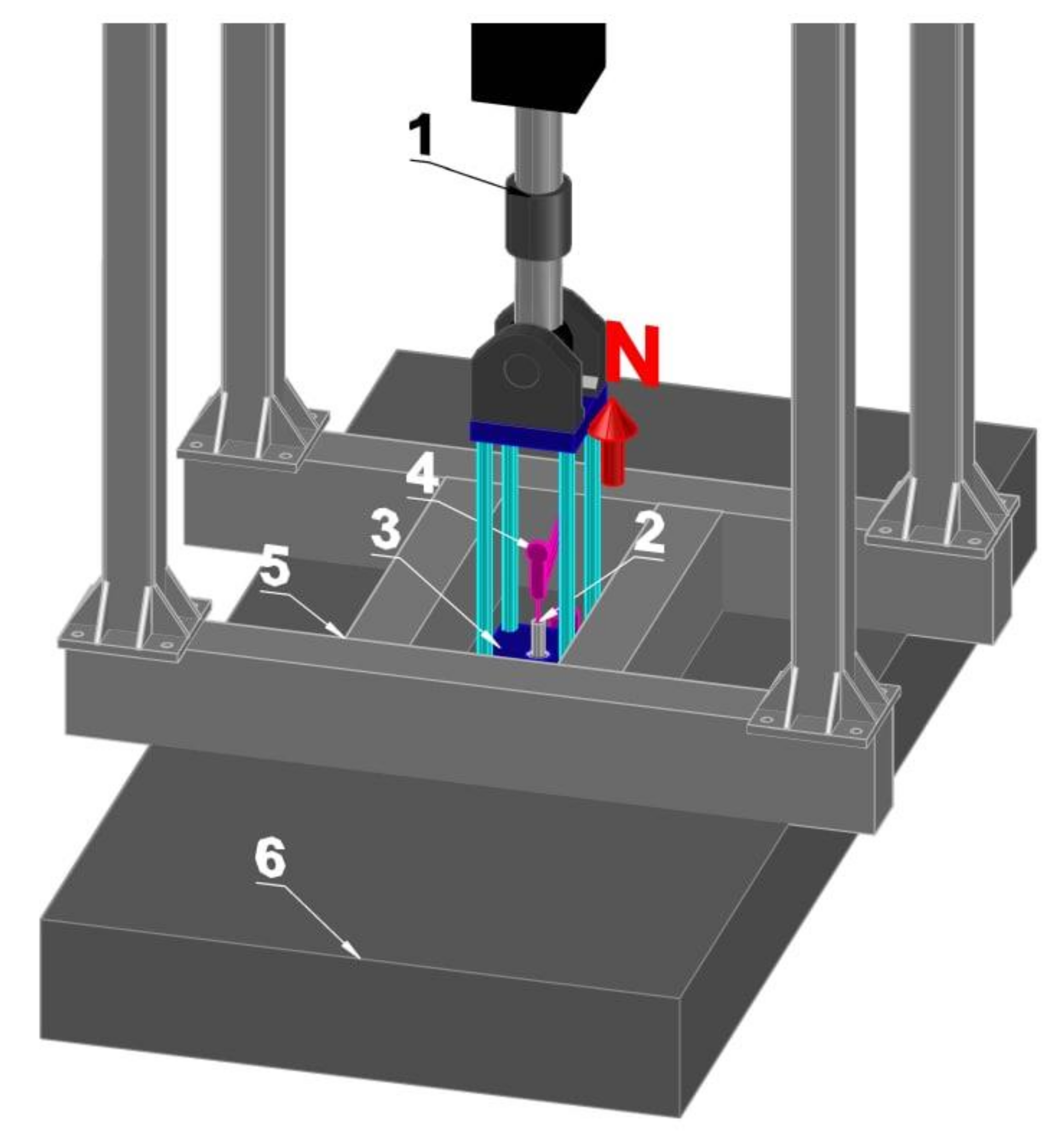
The experimental study of anchors consisted of tensile static and multi-cyclic dynamic loads applied along the anchor axis. A series of specimens was tested according to the described methodology. The series had five specimens subjected to static loading and five specimens subjected to multi-cyclic dynamic loading. The anchor loading pattern is shown in
Figure 6.
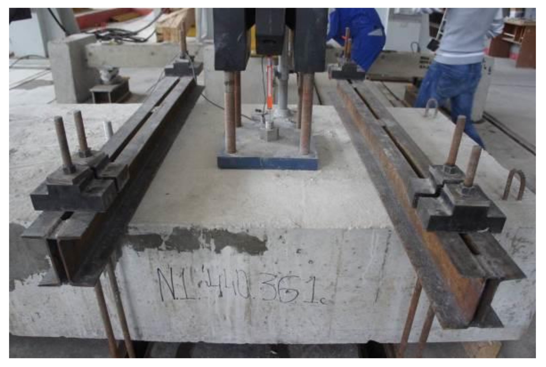
An experimental setup was used during the studies; its general view is shown in
Figure 7. The load was transferred from the loading frame to the anchor through a steel plate fixed to the hydraulic cylinder by steel studs (
Figure 6). A reconfigurable loading frame (CFM Schiller, Roetgen, Germany, 2014), equipped with hydraulic cylinders (MTS, Eden Prairie, MN, USA, 2014) was used in the experiment. The maximum load, generated by one hydraulic cylinder, was 250 kN. Two hydraulic cylinders could be used at a time to rise the load to 500 kN. Two clamps and studs were used to fasten the concrete block to the reinforced floor.
In the process of testing, the load–displacement diagram was made to describe static and dynamic multi-cyclic loading. An SPD-100C linear displacement sensor (Tokyo Sokki Kenkyujo, Tokyo, Japan, 2012) with the measurement range of 0–100 mm and the division value of 0.01 mm was used to measure the anchor displacements.
Seismic loading was simulated during multi-cyclic dynamic loading tests according to ETAG 001 [
33]. The loading characteristic is provided in
Table 2, where
(
is the limit value of the pull-out force determined in the course of the static load testing, when the crack opening was equal to
mm). The loading frequency was 0.5 Hz. Dynamic multi-cyclic loading parameters are provided in
Table 2.
After the completion of multi-cyclic dynamic loading, the specimen was subjected to static loading until its failure.
The diagrams, made as a result of testing, were used to construct intrinsic curves based on the maximum values obtained for the cycles. The values of the plasticity coefficient were determined using the formula:
where
is the deformation value under maximum loading;
is the value of the elastic phase of deformation.
3. Results and Discussion
3.1. Failure Mechanisms of Anchors Embedded in a Concrete Base
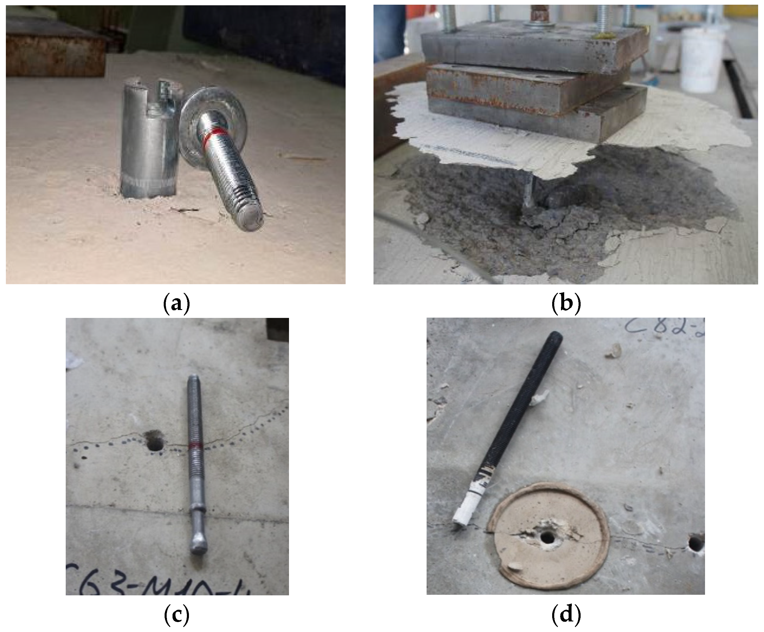
The results of the study demonstrate four failure mechanisms of anchors embedded in a concrete base that has a crack: the anchor material failure (
Figure 8a), the base concrete failure (
Figure 8b), the slippage at the interface between the anchor and the concrete base (
Figure 8c), and the failure at the interface between the adhesive composition and the concrete base (
Figure 8d).
In case of the anchor material failure, the bearing capacity of such an anchorage is determined by the strength of the anchor material (the steel).
The base concrete failure is accompanied by the concrete cone breakout. According to the laws of concrete mechanics, if this failure mechanism is implemented, the bearing capacity is determined by the tensile strength of concrete.
The slippage failure at the interface between the anchor and the concrete base has two options: option A is the anchor slippage in the base, while option B is the slippage that occurs at the initial stage of the anchor loading. Further, the slippage process stops, the concrete base fails, and the concrete cone breakout occurs. If the failure involves the anchor slippage in the base, the bearing capacity is determined by the mechanisms of interaction between anchor elements and the surface of the concrete base. If the failure involves the slippage at the initial stage of anchor loading and the slippage stops, the bearing capacity is determined by the tensile strength of concrete. The failure starts when frictional forces are overcome and the anchor starts slipping in concrete; hence, the cross-section of the concrete resisting the loading is reduced. If the loading exceeds the concrete strength, the anchorage fails in the process of the concrete cone breakout.
In case of failure of an anchor at the interface between the adhesive composition and the concrete base, the bearing capacity is determined by the adhesive interaction between the adhesive composition and the contact surface of the concrete base. It is noteworthy that presently there are several experimentally verified models that describe modes of the contact interaction between dissimilar materials, including the models that take account of adhesion [
34,
35,
36]. The development of the model, describing the adhesive interaction between the adhesive composition of anchors and the concrete base, was not the subject of research conducted by the authors.
The studies have found that cast-in-place anchors have two principal failure mechanisms, including the anchor material failure (
Figure 8a) and the base concrete failure (
Figure 8b). The type of the failure mechanism is determined by the anchor embedment depth, as well as the strength characteristics of concrete and the anchor material. Patterns of the cast-in-place anchor embedment in a concrete base lack binding standards. The embedment depth of cast-in-place anchors is determined by an anchorage designer, acting from his knowledge and using the base reinforcement patterns. The prediction of the failure mechanism of a cast-in-place anchor, having preset reliability, is quite a challenging task, but the results of the experimental studies allow to obtain reliable data. The established practice of insufficient standardization of cast-in-place anchor embedment patterns has necessitated the testing of such anchors at different depths of their embedment.
As a result of the completed research, the authors have identified the threshold value of the cast-in-place anchor embedment depth, at which the strength of the anchor anchorage in concrete exceeds the strength of the anchor material. If anchor embedment depths are equal to or greater than the threshold value, the anchorage failure follows the anchor material failure pattern. If embedment depths are less than the threshold value, the anchorage failure follows the concrete failure pattern and is accompanied by the concrete cone breakout. As a result of testing, the authors have identified the threshold (minimal) cast-in-place anchor embedment depths (with account taken of the anchor diameter and the steel strength), at which the strength of the anchor anchorage in concrete exceeds the anchor strength and triggers the anchor material failure mechanism (
Table 3).
The results of research into the failure mechanisms of cast-in-place anchors allow to reasonably apply the pattern of their embedment in a concrete base to ensure the implementation of the required deformation pattern, featuring some extent of the plastic deformation phase.
Anchors, embedded in the prefabricated base, may have all four types of failure mechanisms: the anchor material failure (
Figure 8a), the base concrete failure (
Figure 8b), the slippage at the interface between the anchor and the concrete base (
Figure 8c), and the failure at the interface between the adhesive composition and the concrete base (
Figure 8d).
Table 4 shows the typical failure mechanisms of anchors, embedded in a prefabricated concrete base, depending on the type of anchorage and the strength of the base concrete.
3.2. The Effect Produced by the Extent of the Concrete Base Damage on the Bearing Capacity of Anchors
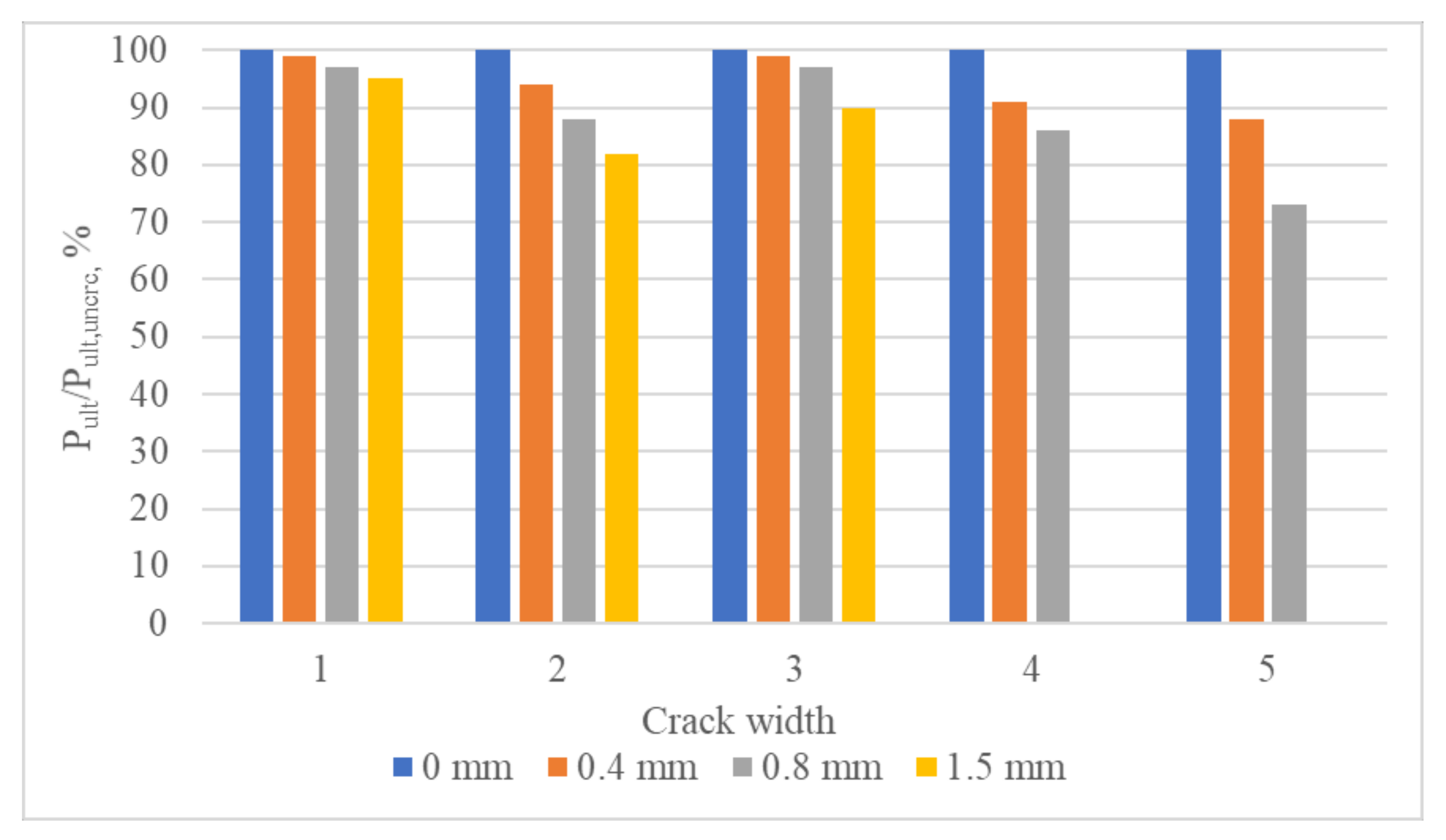
The research findings about the effect of the concrete (reinforced concrete) base damage on the bearing capacity of anchors subjected to axial static loading, if the base crack opening width is equal to 0, 0.4, 0.8, or 1.5 mm, show that the extent of this effect is determined by the anchorage failure mechanism.
In case of implementation of the anchor material (steel) failure mechanism, cracks in the base concrete have no significant effect on the anchor bearing capacity, the reduction does not exceed 5%. In case of the base concrete failure and the slippage failure, the crack opening width significantly affects the bearing capacity, and the bearing capacity reduction reaches 26%.
The values of the bearing capacity of anchors for the cases when (1) the base concrete has no cracks and (2) the crack opening width is 0.4 mm are taken from the research project [
37].
Hence, the effect of the state of an earthquake-damaged concrete (reinforced concrete) base must be considered while calculating the bearing capacity of anchors. The effect of a damaged anchor base, subjected to multi-cyclic dynamic loading, will be studied at the next stage of the research project.
Figure 9 shows the bearing capacity of anchorages subjected to the axial tensile static loading for cases of different values of the base crack opening width (0, 0.4, 0.8, and 1.5 mm) and anchor types (the load is presented as the percentage relative to the failure-inducing load level, applied to an anchorage in a crack-free base).
3.3. The Deformability of Anchors Embedded in the Concrete Base Damaged as a Result of an Earthquake
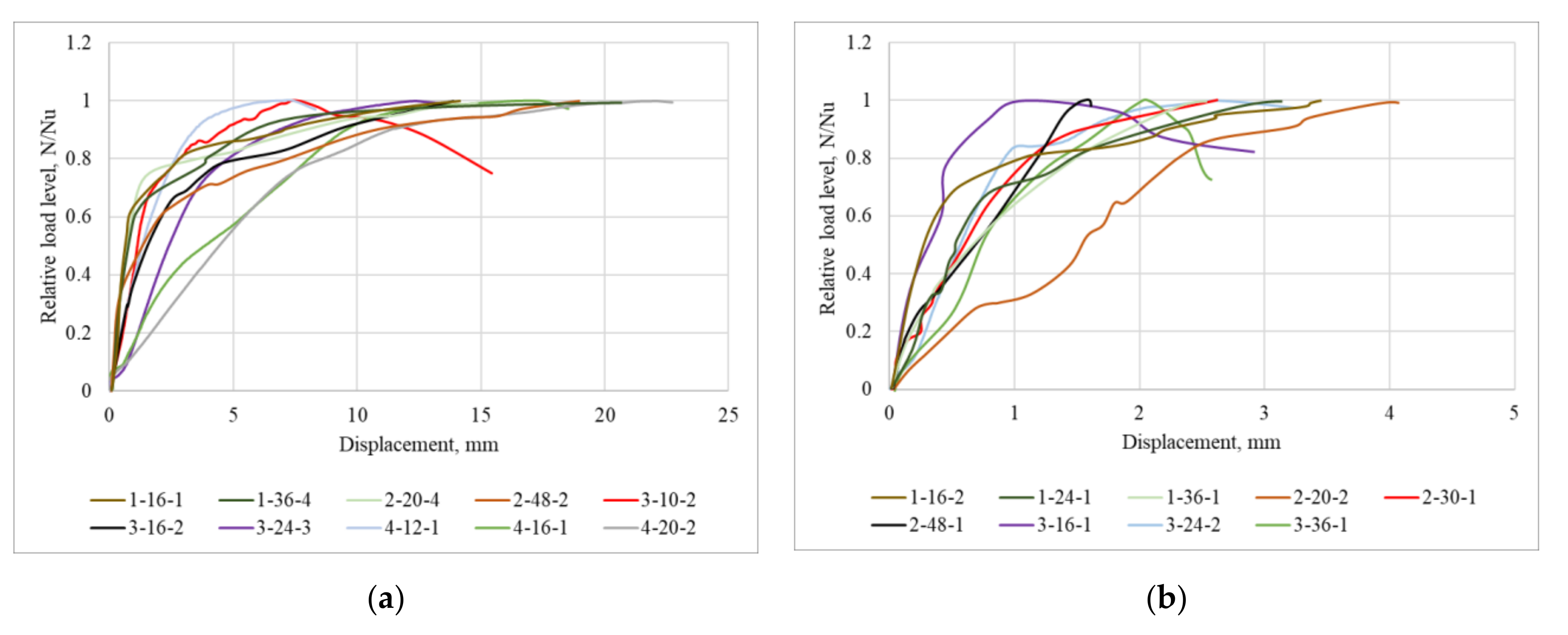
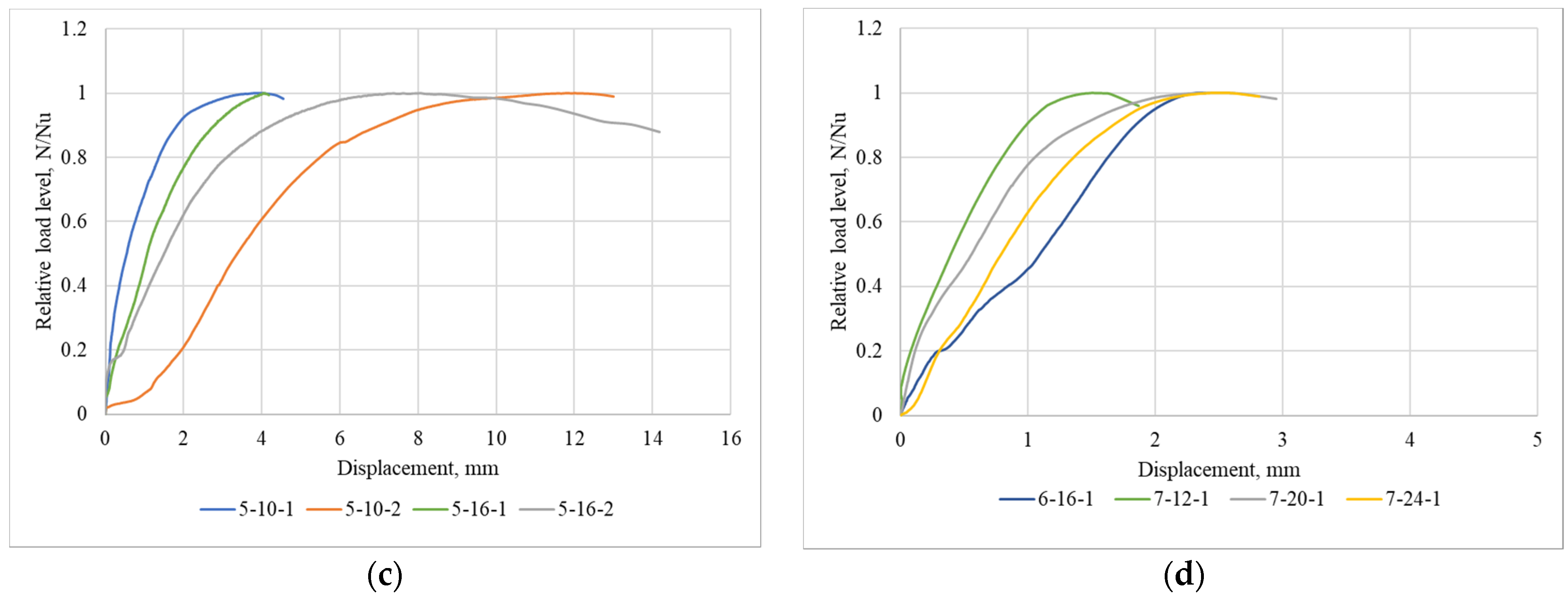
The deformation patterns of anchors embedded in concrete bases damaged by seismic loads are determined by the failure mechanisms.
The load–displacement diagrams made based on the failure mechanisms triggered by static loads are shown in
Figure 10 (values of loads are presented relative to the failure-inducing load level).
The anchorage deformation accompanied by the anchor material failure follows the elastoplastic pattern having pronounced phases of elastic and plastic deformation. The correlation between the total deformation phase and the plastic deformation phase is determined by the mechanical characteristics of the anchor material (steel), which seems quite logical. The more yielding the anchor steels, the higher the plasticity of such an anchorage.
The anchorage deformation accompanied by the base concrete failure follows the elastic-brittle pattern. Its plastic phase is insignificant, and some cases of failure lack it. This type of failure is accompanied by the concrete cone breakout, which represents the brittle fracture of concrete under tensile stresses.
The anchorage deformation accompanied by the slippage failure has two options. The slippage of an anchor follows the elastoplastic pattern having pronounced phases of elastic and plastic deformations. The correlation between total and plastic deformation phases is determined by the interaction between anchor elements and the contact surface of the concrete base. Different types of anchors, having different anchoring elements, demonstrate different correlations between elastic and plastic deformation phases. Having analyzed the research findings, the authors chose a conservative (minimal) value of this correlation that corresponds to the elastic-brittle pattern.
The deformation of an anchorage accompanied by the slippage at the initial loading stage, further slippage stops, and concrete cone breakout follows the elastic-brittle deformation pattern. The slippage phase is unsteady; hence, it cannot be explicitly defined. Having analyzed the research findings, the authors chose the conservative (minimal) value of the correlation, corresponding to the minimal value of the slippage phase.
The deformation of an anchorage at the interface between the adhesive composition and the concrete base is determined by the extent and mechanisms of the adhesive interaction between the adhesive composition and the contact surface of the concrete base. In case of static loading, the plastic deformation phase is insignificant, which corresponds to the elastic-brittle deformation pattern.
3.4. The Effect of Multi-Cyclic Dynamic Loading on the Bearing Capacity and Deformability of Anchors Embedded in a Concrete Base Damaged as a Result of an Earthquake
The results of the study on the deformation and failure of different types of anchors embedded in a base having a crack and subjected to static and multi-cyclic dynamic loads were used to identify differences in (1) their deformation patterns and values and (2) their bearing capacity values.
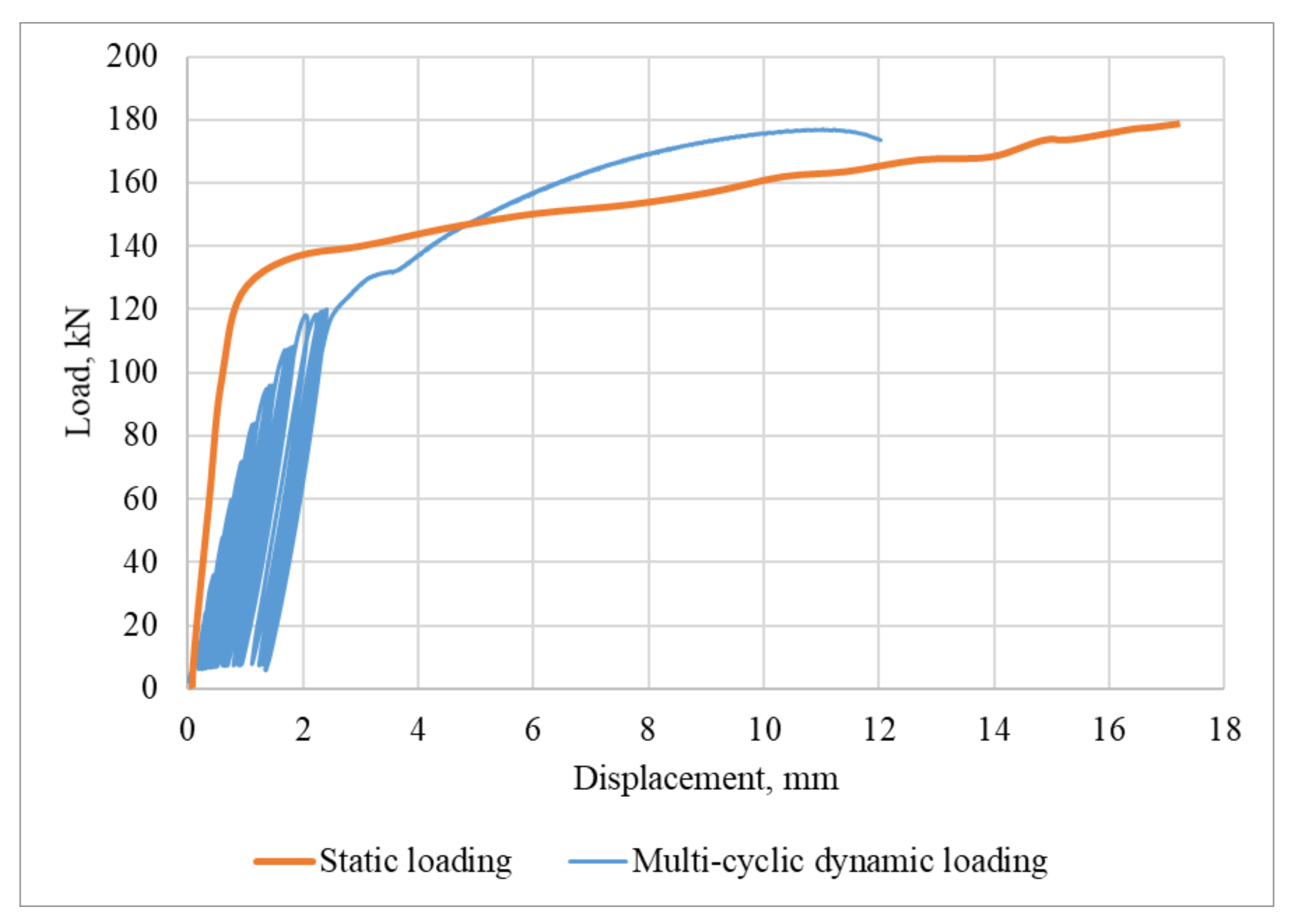
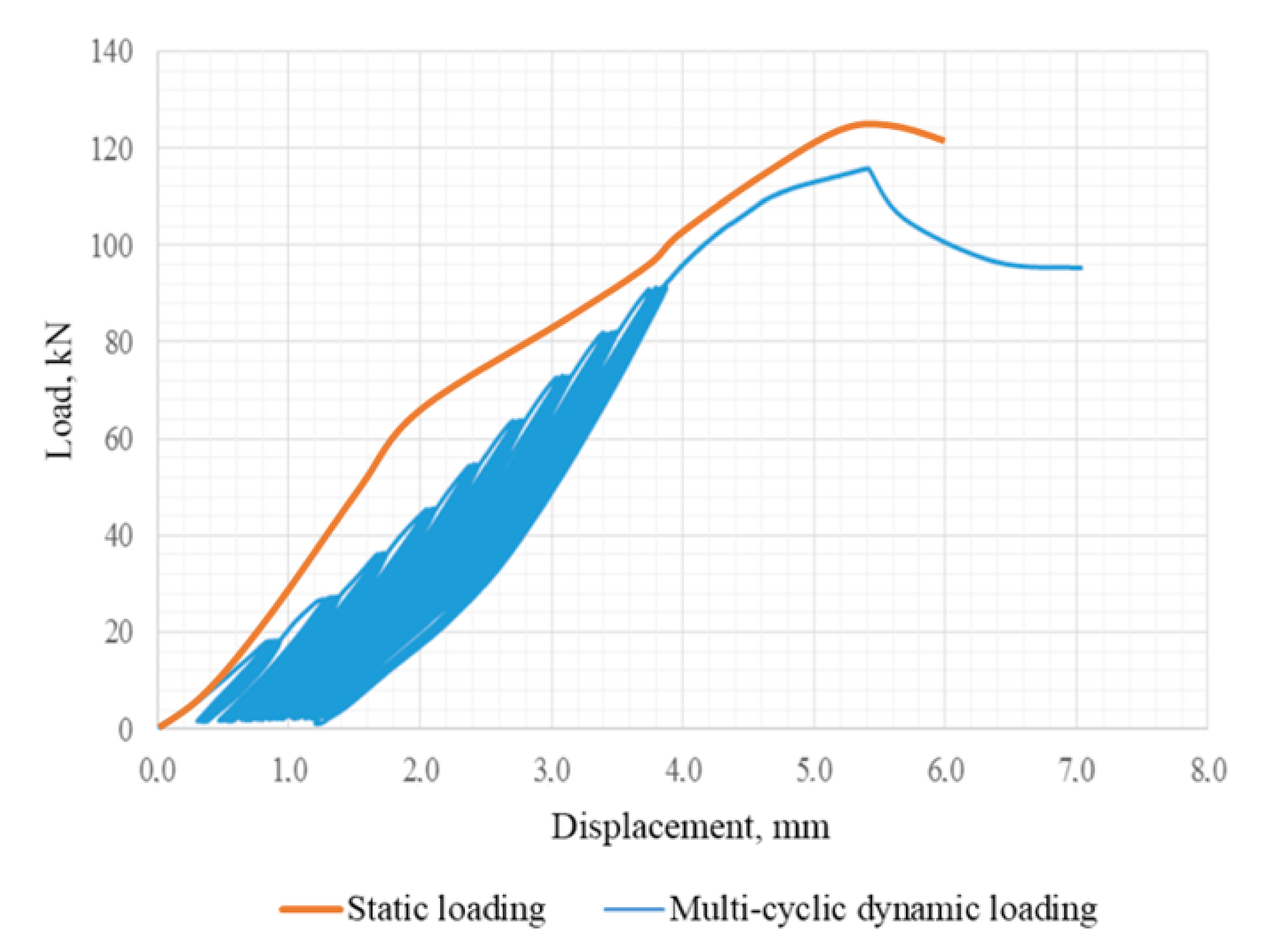
The following facts were identified for the case of the anchorage failure due to the failure of the anchor material (
Figure 11):
Patterns of failure caused by static and dynamic loading are nearly identical. The failure process follows the elastoplastic pattern. Substantial total displacements (up to 20 mm) occur; they are accompanied by extensive plastic deformations. The bearing capacity of an anchorage is determined by the strength of the anchor material (steel). In the elastic phase of deformation under multi-cyclic dynamic loading a 15–20% increase in displacements is observed in comparison with elastic displacements under static loading. In case of multi-cyclic dynamic loading, a 2–4% reduction in the bearing capacity and a 20–35% reduction in total displacements is observed.
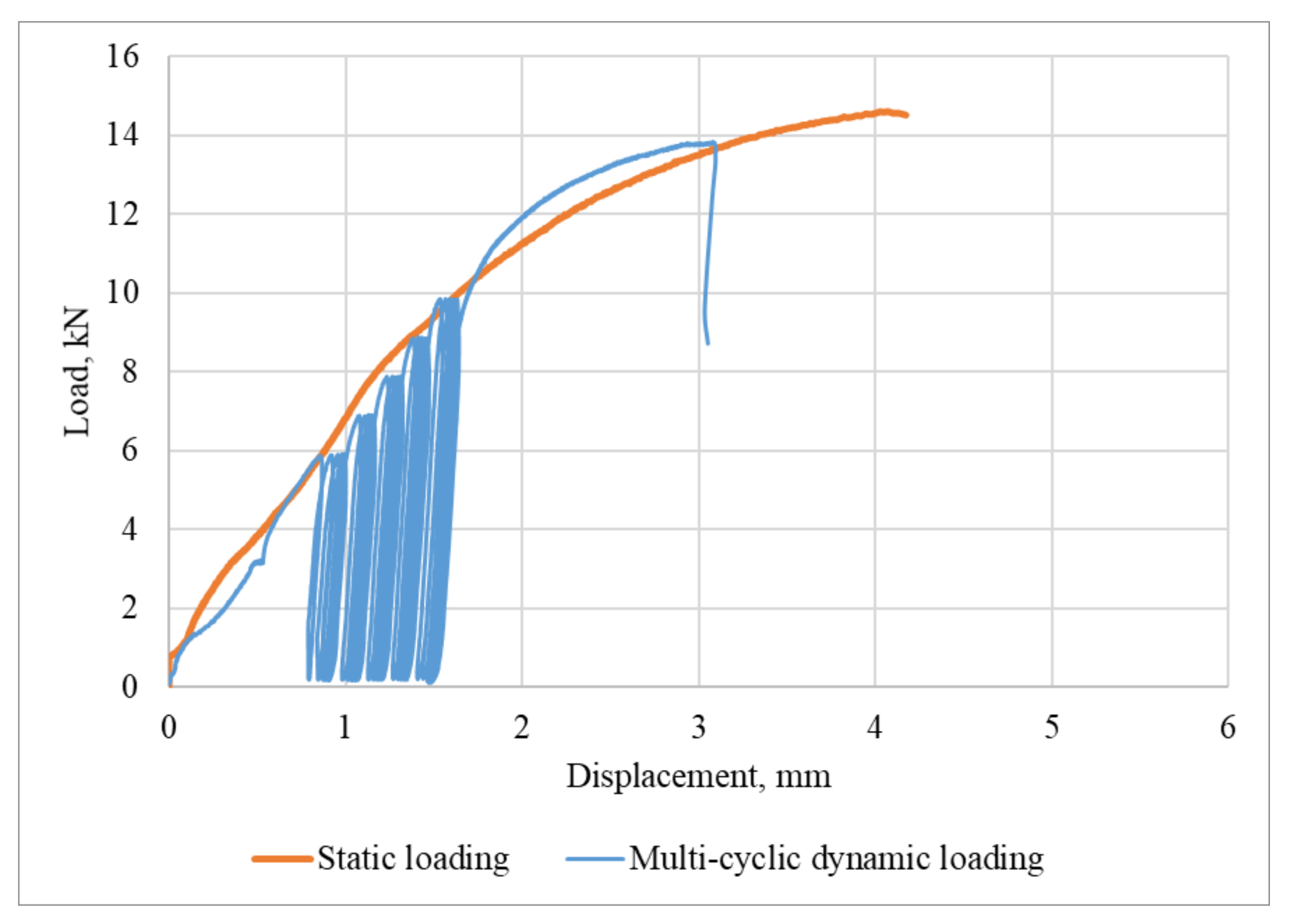
It has been established that, in case of anchorage failure due to the base concrete failure (
Figure 12), patterns of failure under static and multi-cyclic dynamic loading are quite close. Elastic-brittle failure mechanisms, accompanied by the concrete cone breakout, dominate. Total displacements do not exceed 6 mm, and the plastic deformation phase is minimum. The bearing capacity of an anchorage is determined by the strength of concrete in the process of the concrete cone breakout with an apex angle of 50–60°. In the elastic deformation phase displacements rise by 8–15% under multi-cyclic dynamic loading if compared with elastic displacements under static loading. A 2–10% reduction in total displacements and an 8–15% reduction in the bearing capacity of an anchorage is observed under multi-cyclic dynamic loading.
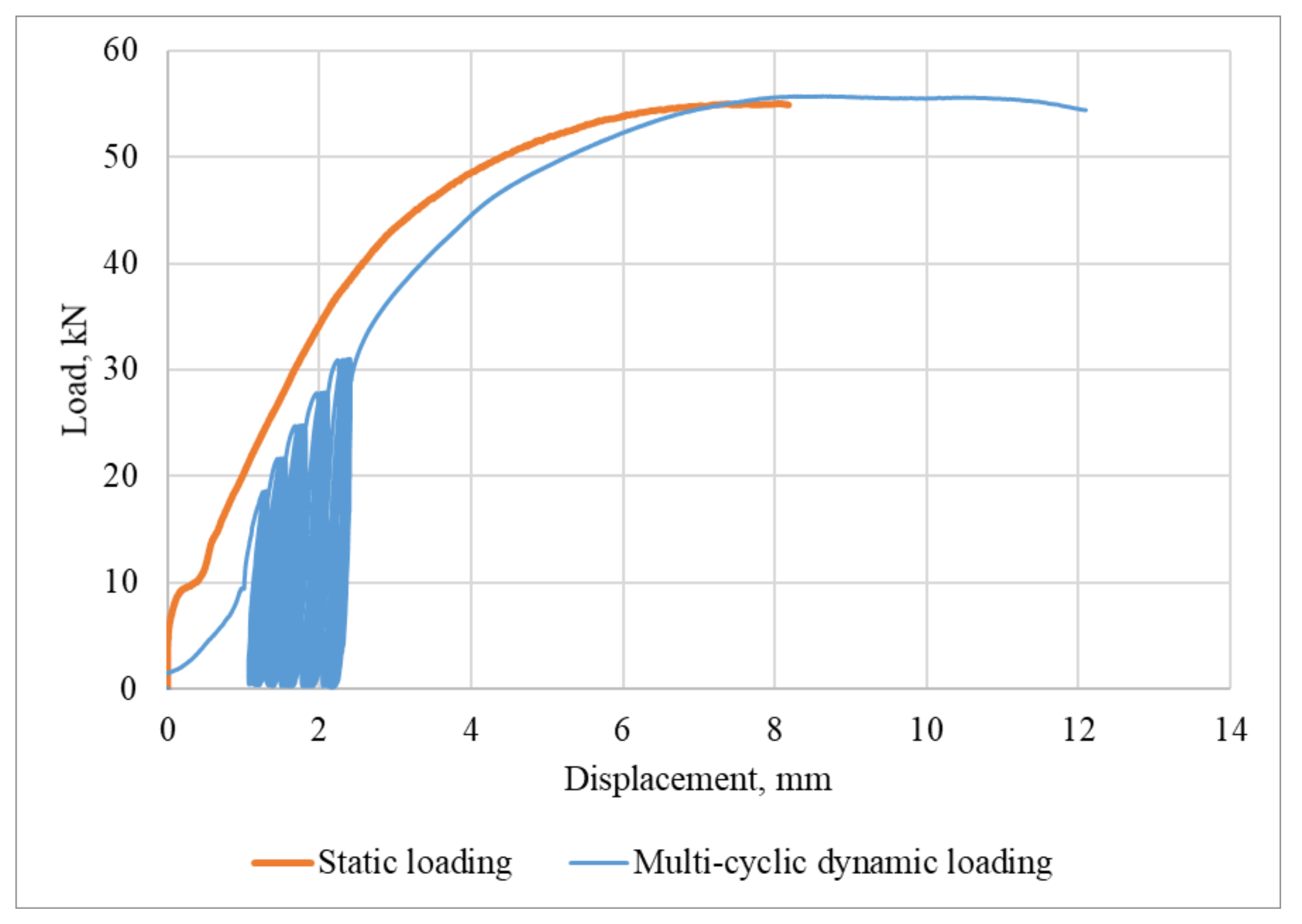
It was found that in case of the anchorage failure due to the anchor slippage in the base concrete (
Figure 13), failure patterns under static and multi-cyclic dynamic loading were quite close. The failure process followed the elastoplastic pattern. Maximal total displacements reached 14 mm with a substantial share of nonlinear deformations. The bearing capacity of an anchorage is determined by the value of the friction force arising at the interface between the anchor and the concrete surface of a drilled hole. In the elastic deformation phase displacements rise by 20–22% under multi-cyclic dynamic loading in comparison with elastic displacements under static loading. Under the multi-cyclic dynamic loading of anchors, a 9–17% reduction in total displacements and a 5–10% reduction in the bearing capacity of an anchorage is observed.
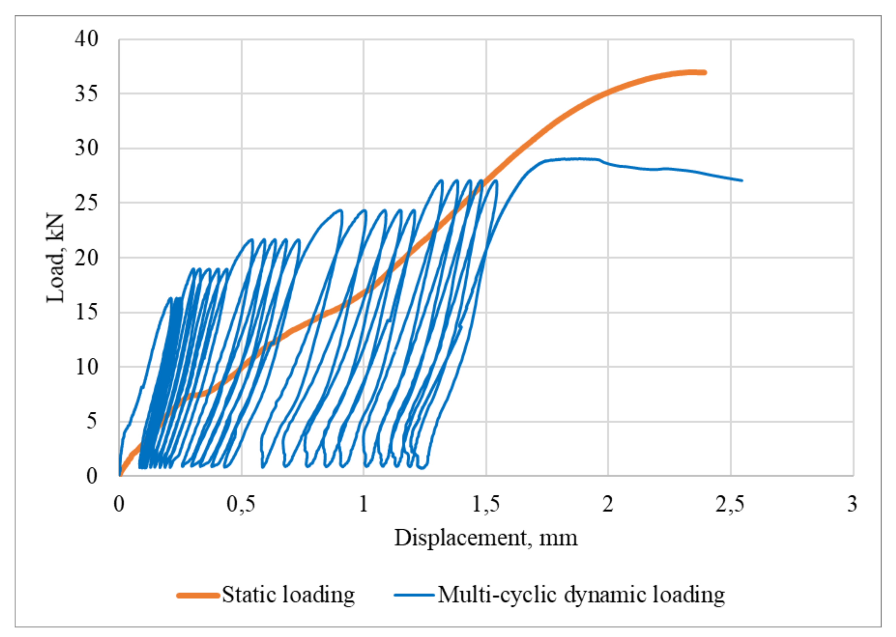
In case of anchorage failure due to slippage at the initial stage of anchor loading and subsequent failure of the base concrete (
Figure 14), patterns of failure under static and multi-cyclic dynamic loading have substantial differences. Under static loading, an insignificant phase of plastic deformations is observed; this phase is followed by the failure. The failure process follows the elastic-brittle pattern.
Under multi-cyclic dynamic loading, a more pronounced phase of elastic deformations is observed; it is followed by a limited phase of plastic deformations implemented according to the slippage failure pattern. This phase is completed when the anchor is stuck in the concrete base. Next, the concrete cone failure occurs, and it is accompanied by the concrete cone breakout. The conservative solution is to characterize this failure as elastic-brittle. Maximum total displacements under static loading do not exceed 5 mm, and the share of elastoplastic deformations is minimum. The bearing capacity of the anchorage is determined by the strength of concrete during the concrete cone breakout with an apex angle of 60–65°. Under multi-cyclic dynamic loading a 5% decrease in the bearing capacity of an anchorage is observed after the cyclic loading, and total displacements decrease by 25–30%.
The failure of anchorages at the interface between the adhesive composition and the base (
Figure 15) has the following characteristics:
Patterns of failure under static and multi-cyclic dynamic loading have substantial differences: under static loading, the deformation diagram is close to the linear one. Under multi-cyclic dynamic loading, the stepwise growth of deformations is observed at the initial stage, then the deformation growth rate decelerates, and a pronounced plastic deformation phase is formed. The predominant types of anchor failure mechanisms are elastic-brittle (under static loading) and elastoplastic (under multi-cyclic dynamic loading). Maximum total displacements reached 2.5 mm. The bearing capacity of an anchorage is determined by the strength of the adhesion contact between the adhesive composition and concrete. In case of multi-cyclic dynamic loading, the bearing capacity of an anchorage falls by 5–7% after the cyclic loading.
Having analyzed the results of the research, the authors determined the values of plasticity coefficients for different mechanisms of the anchorage failure. For the elastic-brittle mechanism ; for the elastoplastic mechanism .
The analysis of anchor failure mechanisms, categorized by the types of anchors, allows to make the following general conclusions:
If
cast-in-place anchors (bent, with an anchor plate, with a bar hook) are embedded to the depth that ensures sufficient anchorage (see
Table 3), the anchor material (steel) fails. If the embedment depth of cast-in-place anchors is insufficient, concrete fails and this process is accompanied by minor plastic deformations.
In case of post-installed anchors, their embedment depth is pre-set by the anchor manufacturer. In the studies, the type of failure is determined by the type of anchor bolts and the base concrete class. For undercut anchors, the most characteristic failure is the plastic failure of the anchor material (steel). However, for large-diameter undercut anchors (M20) embedded in concrete grade C25/30, elastic-brittle concrete failure was observed. An increase in the concrete class (C30/37 and higher) and a corresponding increase in the concrete strength triggered the failure of the anchor material (steel).
For expansion anchors, the principal failure mechanism is anchor slippage in concrete; however, if the base concrete strength is low (C25/30 and below), a combined failure mechanism composed of slippage at the initial stages of loading, subsequent concrete cone breakout, and a reduction in plastic deformations is observed.
The failure of adhesive anchors occurs at the interface between the adhesive composition and the concrete base. The anchorage failure mechanism is elastic-brittle (under static loading) and elastoplastic (under multi-cyclic dynamic loading).
All types of anchorages are characterized by:
- -
accumulation of displacements in the process of multi-cyclic dynamic loading;
- -
reduction in total displacements in case of failure under multi-cyclic dynamic loading in comparison with static loading;
- -
reduction in the bearing capacity of an anchorage following the multi-cyclic dynamic loading.
When an anchorage failed due to the failure of concrete, the interface between the adhesive composition and the base, and slippage accompanied by the concrete cone breakout smaller total displacements were recorded both under static and dynamic loading if compared to the anchorage failure due to the failure of steel or slippage.


