
Structural Performance Assessment of Innovative Hollow Cellular Panels for Modular Flooring System


 ,
,  and
and 
Abstract
:1. Introduction
2. Materials and Methods
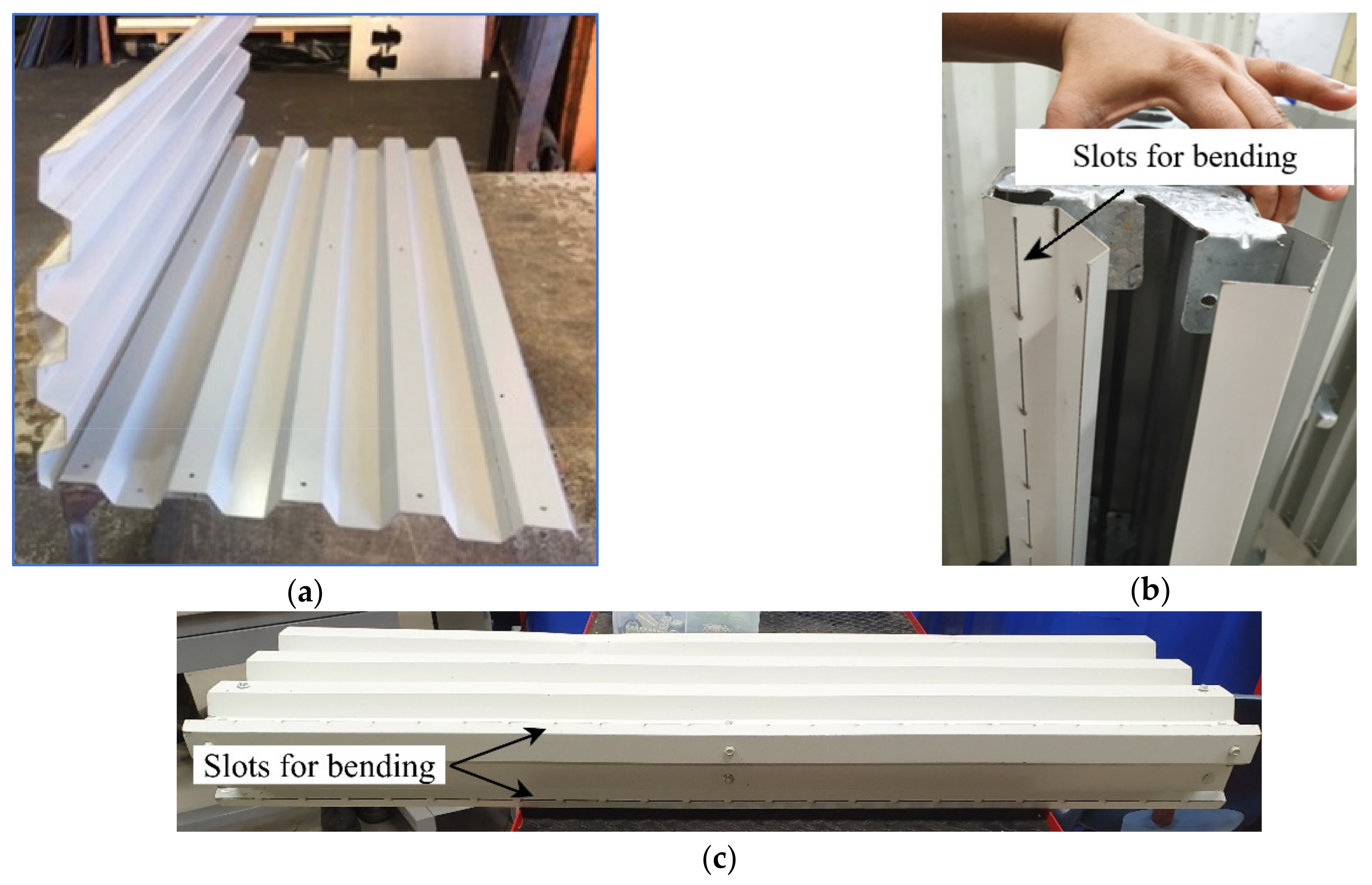
2.1. Fabrication of the Innovative Hollow Cellular Panels
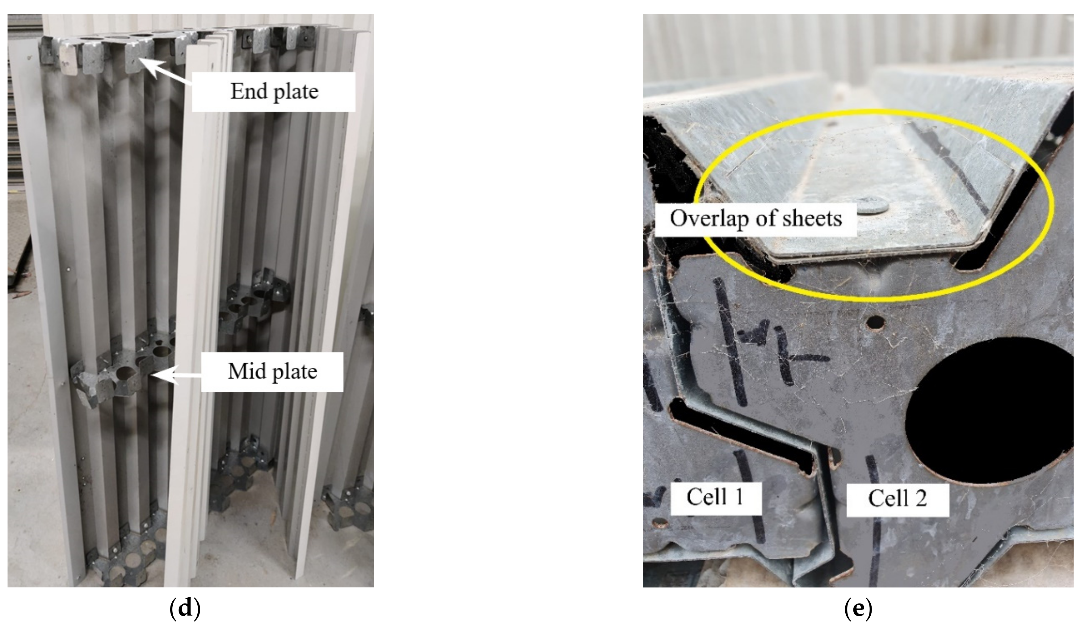
2.2. Panel Details
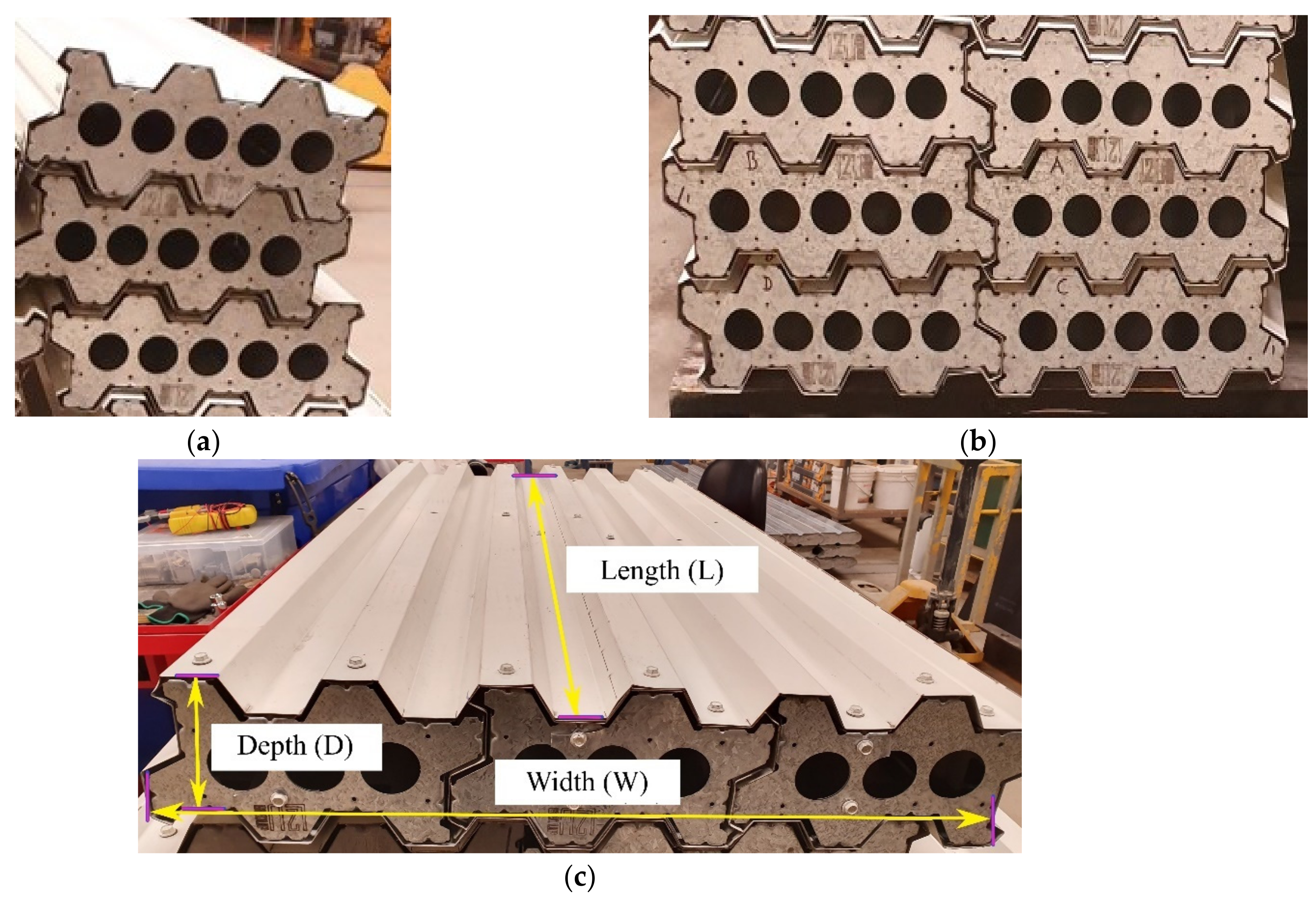
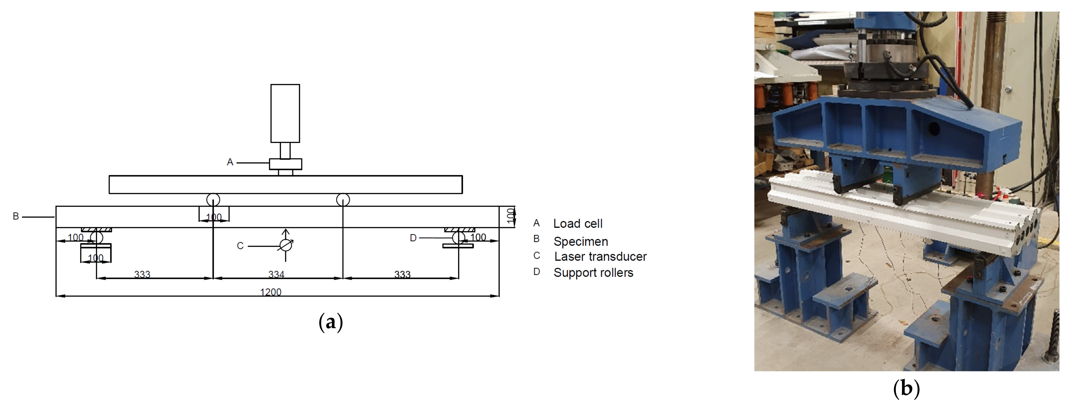
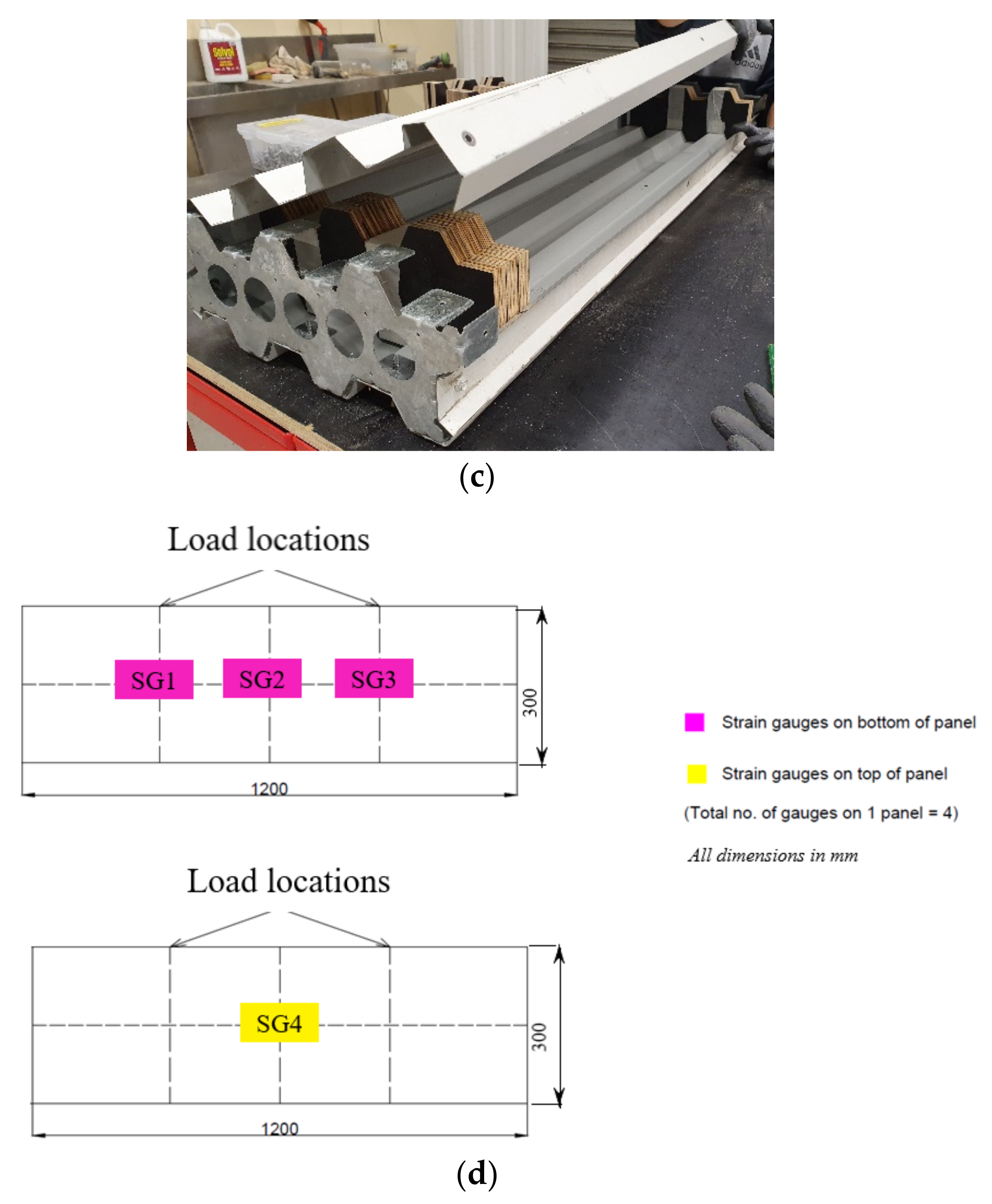
2.3. Test Set-Up
3. Results and Discussion
3.1. Load-Displacement Behaviour
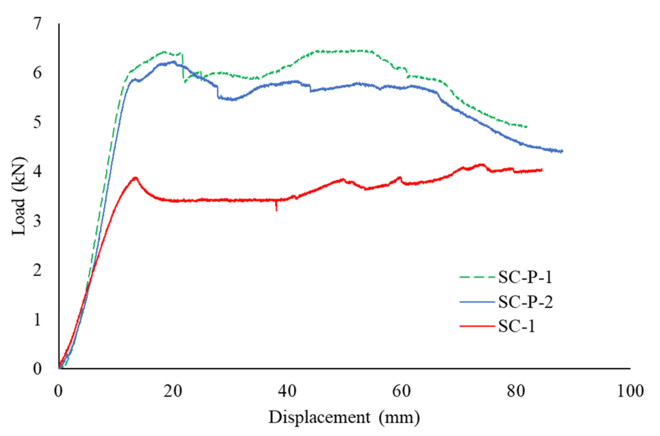
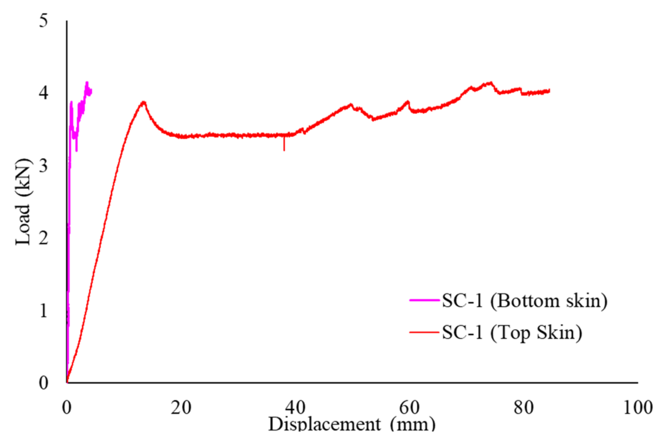
3.1.1. Single-Cell Panels
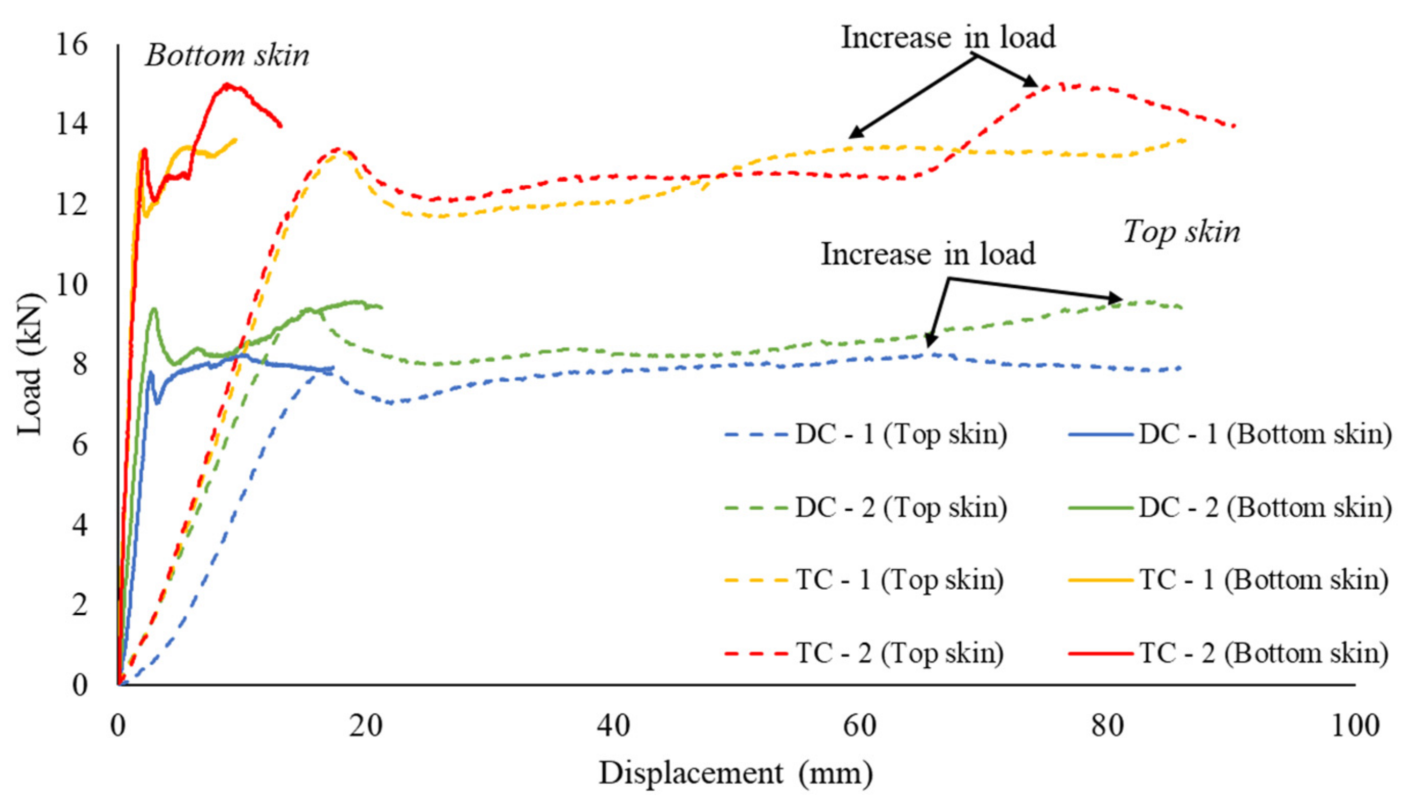
3.1.2. Multi-Cell Panels
3.1.3. Summary of Load-Displacement Behaviour
3.2. Failure Mode
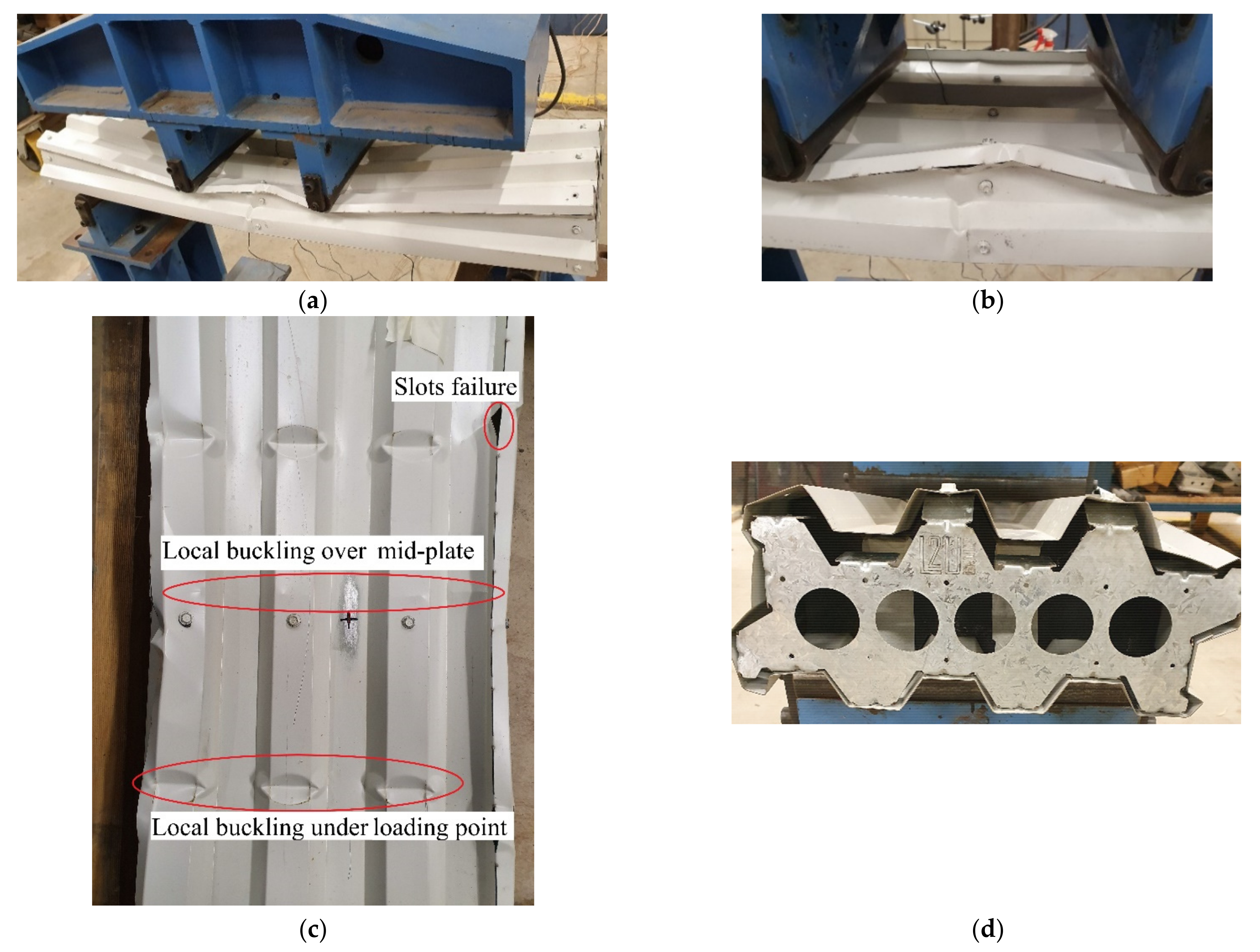
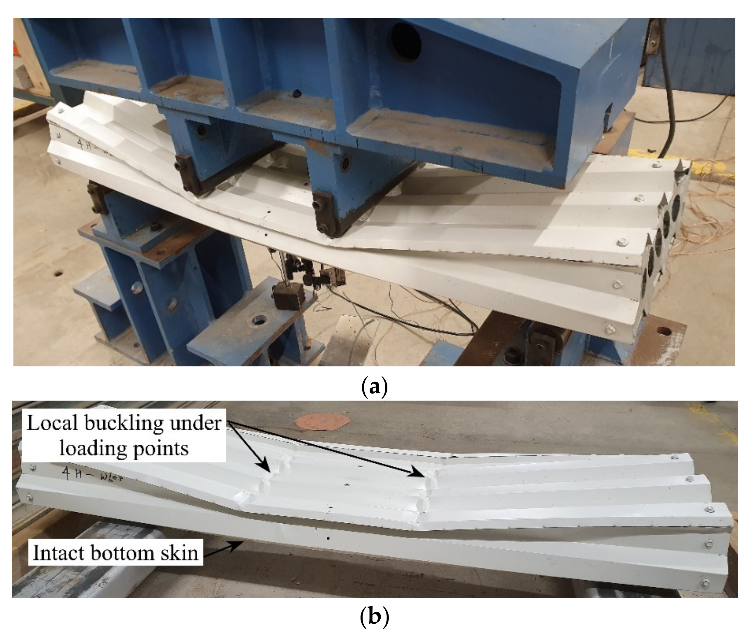
3.2.1. Single-Cell Panels
Panels with Mid-Plate
Panels without Mid-Plate
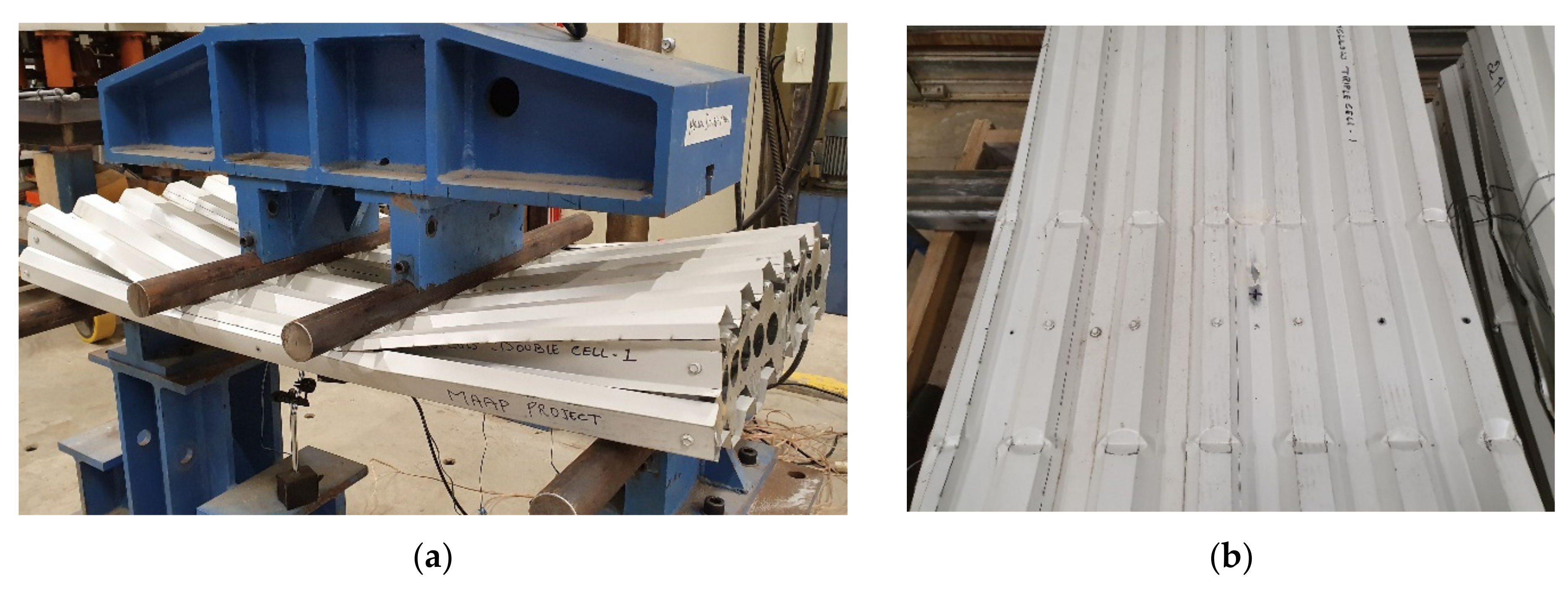
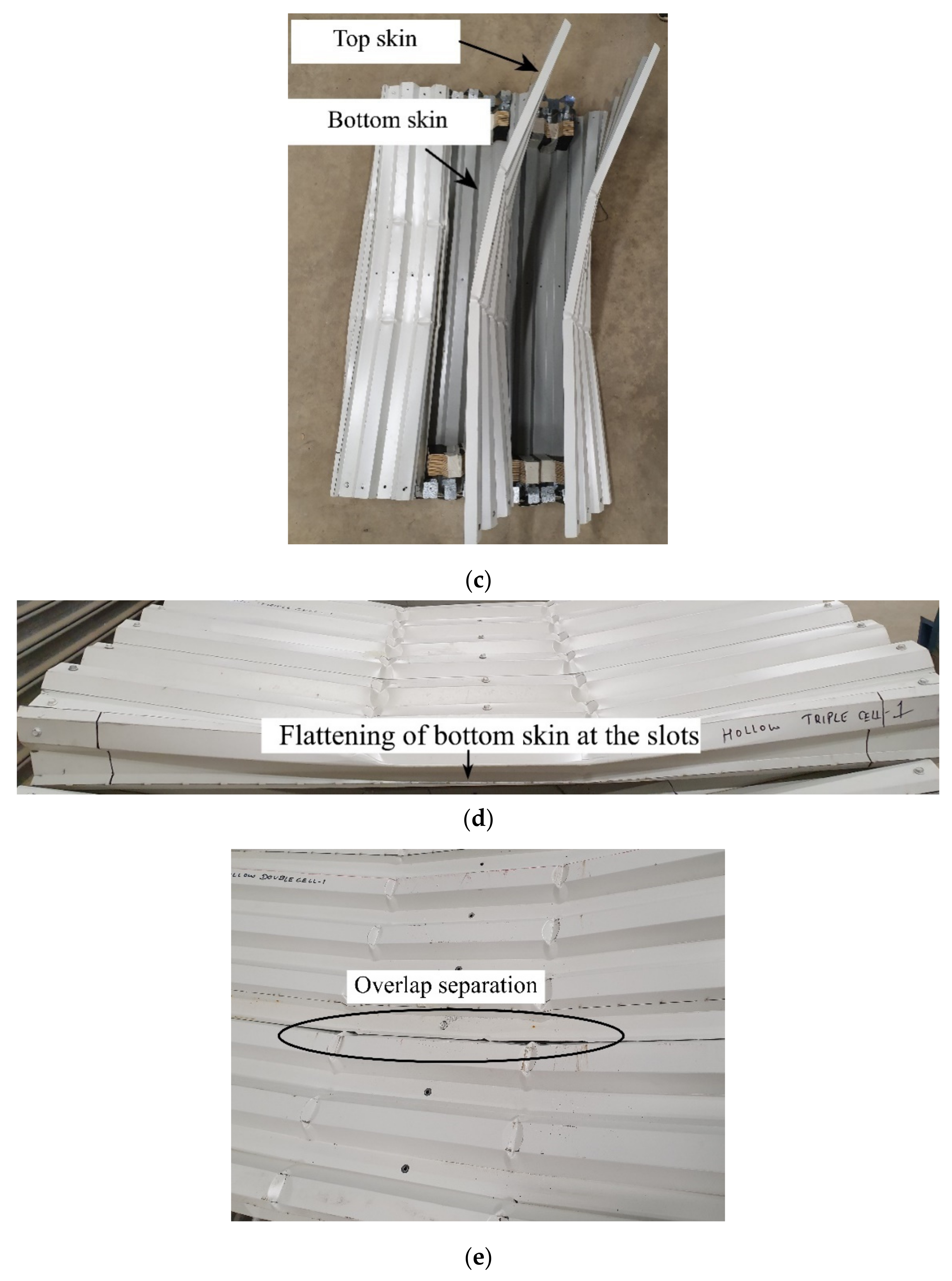
3.2.2. Multi-Cell Panels
3.2.3. Summary of Failure Mode Results
3.3. Load-Strain Distribution
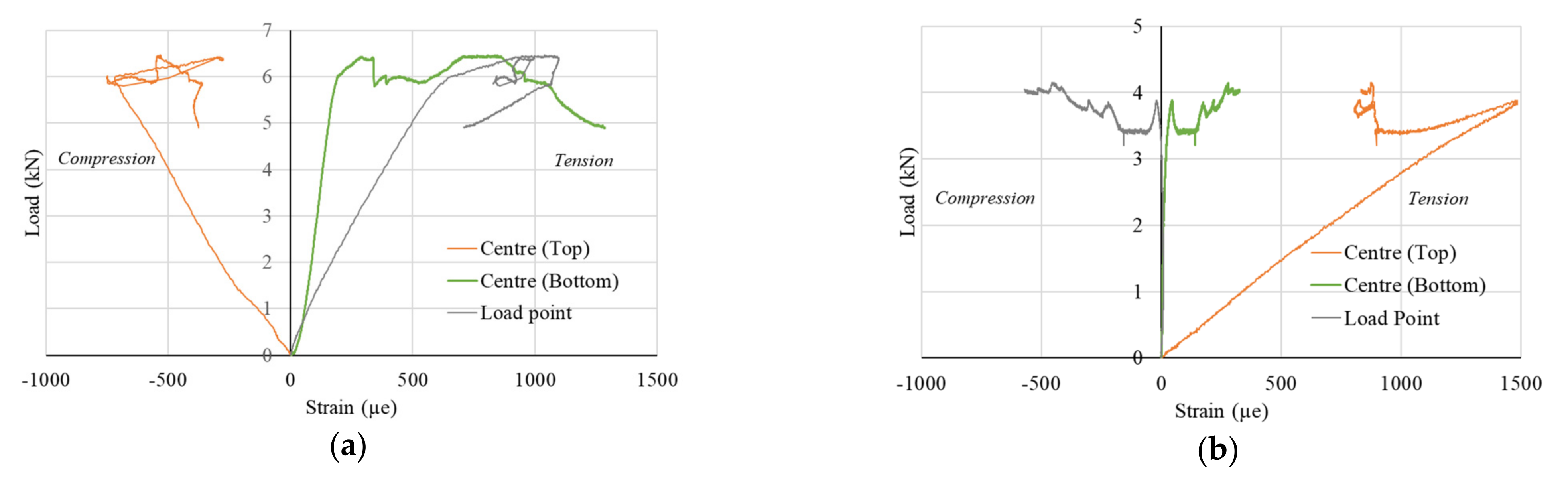
3.3.1. Single-Cell Panels
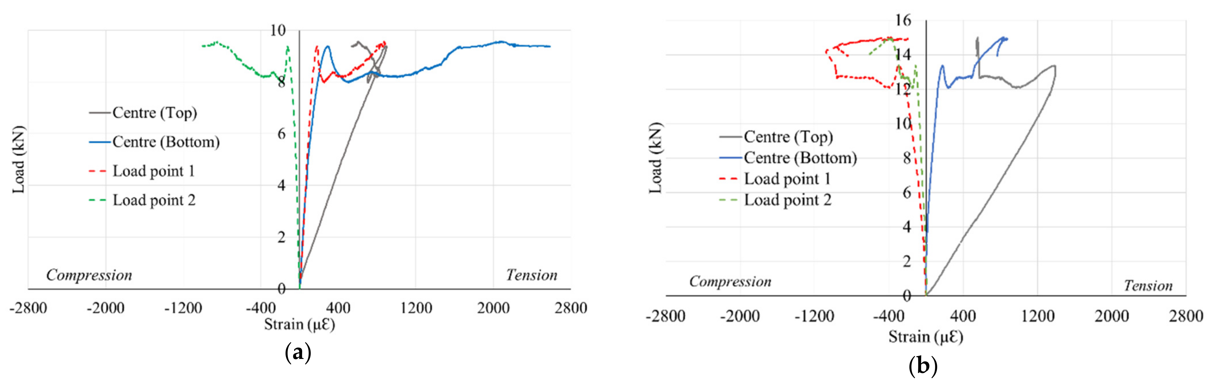
3.3.2. Multi-Cell Panels
3.3.3. Summary of Load–Strain Behaviour
4. Conclusions
- (i)
- The overlap of sheets improves the stiffness of the panels in bending, thereby increasing the load-carrying capacity.
- (ii)
- Triple cell panels achieved 55% higher loads than double cell panels of the same overall dimensions.
- (iii)
- Panels with mid-plate achieved 76% more load than panels without mid-plate due to simultaneous double skin action.
- (iv)
- The flexural failure, local buckling and failure of slots are prominent types of failure observed in various types of specimen configurations used in this study.
Author Contributions
Funding
Institutional Review Board Statement
Informed Consent Statement
Data Availability Statement
Acknowledgments
Conflicts of Interest
References
- Fiume, F.; Callegaro, N.; Albatici, R. Modular Construction for Emergency Situation: A Design Methodology for the Building Envelope. In Sustainability and Automation in Smart Constructions; Springer: Cham, Switzerland, 2021; pp. 131–141. [Google Scholar] [CrossRef]
- Gatheeshgar, P.; Poologanathan, K.; Gunalan, S.; Shyha, I.; Sherlock, P.; Rajanayagam, H.; Nagaratnam, B. Development of affordable steel-framed modular buildings for emergency situations (Covid-19). In Structures; Elsevier: Amsterdam, The Netherlands, 2021; Volume 31, pp. 862–875. [Google Scholar] [CrossRef]
- Zhang, Y.; Lei, Z.; Han, S.; Bouferguene, A.; Al-Hussein, M. Process-oriented framework to improve modular and offsite construction manufacturing performance. J. Constr. Eng. Manag. 2020, 146, 04020116. [Google Scholar] [CrossRef]
- Lin, T.; Lyu, S.; Yang, R.J.; Tivendale, L. Offsite construction in the Australian low-rise residential buildings application levels and procurement options. Eng. Constr. Archit. Manag. 2021. [Google Scholar] [CrossRef]
- Dai Pang, S.; Liew, J.R.L.; Dai, Z.; Wang, Y. Prefabricated Prefinished Volumetric Construction Joining Tech-niques Review. Modul. Offsite Constr. (MOC) Summit Proc. 2016. [Google Scholar] [CrossRef]
- Hussein, M.; Eltoukhy, A.E.; Karam, A.; Shaban, I.A.; Zayed, T. Modelling in Off-Site Construction Supply Chain Management: A Review and Future Directions for Sustainable Modular Integrated Construction. J. Clean. Prod. 2021, 310, 127503. [Google Scholar] [CrossRef]
- Choi, J.O.; Chen, X.B.; Kim, T.W. Opportunities and challenges of modular methods in dense urban environment. Int. J. Constr. Manag. 2019, 19, 93–105. [Google Scholar] [CrossRef]
- Liew, J.; Chua, Y.; Dai, Z. Steel concrete composite systems for modular construction of high-rise buildings. In Structures; Elsevier: Amsterdam, The Netherlands, 2019; Volume 21, pp. 135–149. [Google Scholar] [CrossRef] [Green Version]
- Jang, J.; Ahn, S.; Cha, S.H.; Cho, K.; Koo, C.; Kim, T.W. Toward productivity in future construction: Mapping knowledge and finding insights for achieving successful offsite construction projects. J. Comput. Des. Eng. 2021, 8, 1–14. [Google Scholar] [CrossRef]
- Ferdous, W.; Bai, Y.; Ngo, T.D.; Manalo, A.; Mendis, P. New advancements, challenges and opportunities of multi-storey modular buildings–A state-of-the-art review. Eng. Struct. 2019, 183, 883–893. [Google Scholar] [CrossRef]
- Wang, L.; Webster, M.D.; Hajjar, J.F. Behavior of deconstructable steel-concrete shear connection in composite beams. Struct. Congr. 2015 2015, 876–887. [Google Scholar] [CrossRef] [Green Version]
- Gunawardena, T. Behaviour of Prefabricated Modular Buildings Subjected to Lateral Loads. Ph.D. Thesis, University of Melbourne, Melbourne, Australia, 2016. [Google Scholar]
- Boadi-Danquah, E.; Robertson, B.; Fadden, M.; Sutley, E.J.; Colistra, J. Lightweight modular steel floor system for rapidly constructible and reconfigurable buildings. Int. J. Comput. Methods Exp. Meas. 2017, 5, 562–573. [Google Scholar] [CrossRef] [Green Version]
- Hosseini, M.R.; Chileshe, N.; Rameezdeen, R.; Lehmann, S. Integration of design for reverse logistics and harvesting of information: A research agenda. Int. J. Logist. Syst. Manag. 2015, 20, 480–515. [Google Scholar] [CrossRef]
- Vaz-Serra, P.; Wasim, M.; Egglestone, S. Design for manufacture and assembly: A case study for a prefabricated bathroom wet wall panel. J. Build. Eng. 2021, 44, 102849. [Google Scholar] [CrossRef]
- Razkenari, M.; Fenner, A.; Shojaei, A.; Hakim, H.; Kibert, C. Perceptions of offsite construction in the United States: An investigation of current practices. J. Build. Eng. 2020, 29, 101138. [Google Scholar] [CrossRef]
- Brunesi, E.; Nascimbene, R. Numerical web-shear strength assessment of precast prestressed hollow core slab units. Eng. Struct. 2015, 102, 13–30. [Google Scholar] [CrossRef]
- Hosseini, M.R.; Martek, I.; Zavadskas, E.K.; Aibinu, A.A.; Arashpour, M.; Chileshe, N. Critical evaluation of off-site construction research: A Scientometric analysis. Autom. Constr. 2018, 87, 235–247. [Google Scholar] [CrossRef]
- John, K.; Ashraf, M.; Weiss, M.; Al-Ameri, R. Experimental investigation of novel corrugated steel deck under construction load for composite slim-flooring. Buildings 2020, 10, 208. [Google Scholar] [CrossRef]
- Arrayago, I.; Real, E.; Mirambell, E.; Marimon, F.; Ferrer, M. Experimental study on ferritic stainless steel trapezoidal decks for composite slabs in construction stage. Thin-Walled Struct. 2019, 134, 255–267. [Google Scholar] [CrossRef]
- FormFlow. 2020. Available online: https://formflow.net.au (accessed on 13 December 2021).
- Madsen, T.; Hansen, K.H. Building System. U.S. Patent 8,539,730 B2, 2013. [Google Scholar]
- Lysaght Customflow. 2021. Available online: https://www.lysaght.com/products/customflow (accessed on 13 December 2021).
- Lysaght. 2021. Available online: https://cdn.dcs.lysaght.com/download/lysaght-build-on-inspiration-design-in-steel (accessed on 13 December 2021).
- Liao, J.; Yang, K.Y.; Zeng, J.-J.; Quach, W.-M.; Ye, Y.-Y.; Zhang, L. Compressive behavior of FRP-confined ultra-high performance concrete (UHPC) in circular columns. Eng. Struct. 2021, 249, 113246. [Google Scholar] [CrossRef]
- Rahman, S.K.; Al-Ameri, R. A newly developed self-compacting geopolymer concrete under ambient condition. Constr. Build. Mater. 2021, 267, 121822. [Google Scholar] [CrossRef]


| Panel Type | Panel ID | Panel Dimensions (L × W × D) mm | Width of Individual Cell (W) mm | Number of Panels Tested |
|---|---|---|---|---|
| Single cell (with mid-plate) | SC-P | 1200 × 300 × 100 | 300 | 2 |
| Single cell (without mid-plate) | SC | 1200 × 300 × 100 | 300 | 1 |
| Double cells (without mid-plate) | DC | 1200 × 600 × 100 | 300 | 2 |
| Triple cells (without mid-plate) | TC | 1200 × 600 × 100 | 200 | 2 |
| Total number of panels | 7 | |||
| Panel | Ultimate Load (kN) | Displacement—Top Skin (mm) | Displacement—Bottom Skin (mm) |
|---|---|---|---|
| SC-P-1 | 6.23 | 20.10 | 19.98 |
| SC-P-2 | 6.46 | 21.13 | 21.15 |
| Average | 6.34 | 20.61 | 20.56 |
| SC | 3.60 | 15.30 | 0.91 |
| Panel | Panel Dimensions (mm) | Width of Individual Cell (mm) | Number of Cells | Ultimate Load (kN) | Displacement—Top Skin (mm) | Displacement—Bottom Skin (mm) |
|---|---|---|---|---|---|---|
| DC—1 | 1200 × 600 × 100 | 300 | 2 | 7.81 | 16.46 | 2.61 |
| DC—2 | 1200 × 600 × 100 | 300 | 2 | 9.38 | 15.47 | 2.86 |
| Average | 8.59 | 15.96 | 2.73 | |||
| TC—1 | 1200 × 600 × 100 | 200 | 3 | 13.30 | 18.03 | 1.78 |
| TC—2 | 1200 × 600 × 100 | 200 | 3 | 13.38 | 17.77 | 2.12 |
| Average | 13.34 | 17.90 | 1.95 | |||
| Panel | Panel Dimensions (mm) | Width of Individual Cell (mm) | No. of Cells | Ultimate Load (kN) | Displacement—Top Skin (mm) | Displacement—Bottom Skin (mm) |
|---|---|---|---|---|---|---|
| Single Cell (Without mid-plate) | 1200 × 300 × 100 | 300 | 1 | 3.60 | 15.30 | 0.91 |
| Single cell (With mid-plate) | 1200 × 300 × 100 | 300 | 1 | 6.34 | 20.61 | 20.56 |
| Double Cell | 1200 × 600 × 100 | 300 | 2 | 8.59 | 15.96 | 2.73 |
| Panel | Panel Dimensions (mm) | Width of Individual Cell (mm) | No. of Cells | Ultimate Load (kN) | Displacement—Top Skin (mm) | Displacement—Bottom Skin (mm) |
|---|---|---|---|---|---|---|
| Double Cell | 1200 × 600 × 100 | 300 | 2 | 8.59 | 15.96 | 2.73 |
| Triple cell | 1200 × 600 × 100 | 300 | 3 | 13.34 | 17.90 | 1.95 |
Publisher’s Note: MDPI stays neutral with regard to jurisdictional claims in published maps and institutional affiliations. |
© 2022 by the authors. Licensee MDPI, Basel, Switzerland. This article is an open access article distributed under the terms and conditions of the Creative Commons Attribution (CC BY) license (https://creativecommons.org/licenses/by/4.0/).
Share and Cite
John, K.; Rahman, S.; Kafle, B.; Weiss, M.; Hansen, K.; Elchalakani, M.; Udawatta, N.; Hosseini, M.R.; Al-Ameri, R. Structural Performance Assessment of Innovative Hollow Cellular Panels for Modular Flooring System. Buildings 2022, 12, 57. https://doi.org/10.3390/buildings12010057
John K, Rahman S, Kafle B, Weiss M, Hansen K, Elchalakani M, Udawatta N, Hosseini MR, Al-Ameri R. Structural Performance Assessment of Innovative Hollow Cellular Panels for Modular Flooring System. Buildings. 2022; 12(1):57. https://doi.org/10.3390/buildings12010057
Chicago/Turabian StyleJohn, Keerthana, Sherin Rahman, Bidur Kafle, Matthias Weiss, Klaus Hansen, Mohamed Elchalakani, Nilupa Udawatta, M. Reza Hosseini, and Riyadh Al-Ameri. 2022. "Structural Performance Assessment of Innovative Hollow Cellular Panels for Modular Flooring System" Buildings 12, no. 1: 57. https://doi.org/10.3390/buildings12010057